JP5593708B2 - Air conditioning indoor unit - Google Patents
Air conditioning indoor unit Download PDFInfo
- Publication number
- JP5593708B2 JP5593708B2 JP2010012199A JP2010012199A JP5593708B2 JP 5593708 B2 JP5593708 B2 JP 5593708B2 JP 2010012199 A JP2010012199 A JP 2010012199A JP 2010012199 A JP2010012199 A JP 2010012199A JP 5593708 B2 JP5593708 B2 JP 5593708B2
- Authority
- JP
- Japan
- Prior art keywords
- side member
- indoor unit
- conditioning indoor
- air conditioning
- hole
- Prior art date
- Legal status (The legal status is an assumption and is not a legal conclusion. Google has not performed a legal analysis and makes no representation as to the accuracy of the status listed.)
- Active
Links
Images


Description
本発明は、空調室内機に関し、特に、配管が本体の側方から引き出される空調室内機に関する。 The present invention relates to an air conditioning indoor unit, and more particularly to an air conditioning indoor unit in which piping is drawn out from the side of the main body.
空調室内機の本体ケーシングは、据付時に、そのコーナー部の側面または下面に配管引き出し用の貫通穴があけられる。例えば、特許文献1(特開2002−54821号公報)に開示されている空調室内機では、穴あけ作業を容易にするために、そのコーナー部は別部材で構成されており、その部材の側面または下面に貫通穴が設けられる。 The main body casing of the air conditioning indoor unit is provided with a through hole for drawing out a pipe on the side surface or the lower surface of the corner portion during installation. For example, in an air-conditioning indoor unit disclosed in Patent Document 1 (Japanese Patent Laid-Open No. 2002-54821), in order to facilitate the drilling operation, the corner portion is configured by a separate member, and the side surface of the member or A through hole is provided on the lower surface.
しかしながら、空調室内機の移設によって配管引き出し位置が変更された場合、コーナー部の貫通穴は人目に付き易いので意匠性を低下させる。仮に、貫通穴のないコーナー部を新規に取り付けても本体ケーシングとの境界線が表に現れるので、意匠性の低下は免れない。 However, when the piping pull-out position is changed due to the relocation of the air conditioning indoor unit, the through hole in the corner portion is easily noticeable, so that the design is deteriorated. Even if a corner portion without a through-hole is newly attached, the boundary line with the main body casing appears on the table, so the deterioration in design is inevitable.
本発明の課題は、空調室内機の移設によって配管の引き出し位置が変わったときでも、意匠性が損なわれない空調室内機を提供することにある。 An object of the present invention is to provide an air-conditioning indoor unit that does not impair the design even when the piping drawing position changes due to the transfer of the air-conditioning indoor unit.
本発明の第1観点に係る空調室内機は、配管が本体の側方から引き出されることが可能な空調室内機であって、本体ケーシングと、側面部材と、可動パネルとを備えている。側面部材は、前方端から外側に張り出すように湾曲する前方湾曲面とその前方湾曲面の終端から後方端に向かって内側に入り込むように湾曲する後方湾曲面を有し、本体ケーシングの側面視における外観を担う。可動パネルは、平坦な形状を成す正面部と、正面部の両端から後方に連続して一体的に形成される側面部とを有する。また、側面部材は、本体ケーシングに着脱自在な取付構造によって本体ケーシングの側方を覆うように取り付けられる。そして、正面部は、本体ケーシングの前面部の全部を覆い、側面部は前方湾曲面に沿って側面部材の前半分を覆う。 An air-conditioning indoor unit according to a first aspect of the present invention is an air-conditioning indoor unit in which piping can be drawn from the side of the main body, and includes a main body casing, a side member, and a movable panel. The side member has a front curved surface that curves so as to protrude outward from the front end , and a rear curved surface that curves so as to enter inwardly from the end of the front curved surface toward the rear end. Responsible for the appearance. The movable panel has a front portion that has a flat shape, and side portions that are integrally formed continuously from both ends of the front portion to the rear. Further, the side member is attached so as to cover the side of the main body casing by a mounting structure that is detachable from the main body casing. And a front part covers the whole front part of a main body casing, and a side part covers the front half of a side member along a front curved surface .
この空調室内機では、側面部材は本体ケーシングと一体物ではなく着脱可能であるので、空調室内機の移設によって配管引き出し用の穴が不要になる場合は、穴があけられる前と同等の側面部材に取り替えることができる。その結果、本体ケーシングのコーナー部に穴が残る状態、或は穴を解消する処置を行った痕跡が残る状態は回避されるので、意匠性が低下することはない。 In this air conditioner indoor unit, the side member is not an integral part of the main body casing but can be attached and detached. Therefore, when the hole for pulling out the pipe is not necessary due to the transfer of the air conditioner indoor unit, the side member equivalent to before the hole is made Can be replaced. As a result, a state in which a hole remains in the corner portion of the main body casing or a state in which a trace of a treatment for eliminating the hole remains is avoided, and the design is not deteriorated.
本発明の第2観点に係る空調室内機は、第1観点に係る空調室内機であって、側面部材の形態として、本体ケーシングの側方のうち配管が引き出される側には第1形態が採用され、配管が引き出されない側には第2形態が採用される。第1形態は配管が通るための貫通穴を有し、第2形態は貫通穴を有しない。 The air conditioning indoor unit according to the second aspect of the present invention is the air conditioning indoor unit according to the first aspect, and the first mode is adopted as the side member in the side where the piping is drawn out of the side of the main body casing. The second form is adopted on the side where the piping is not drawn. The first form has a through hole through which the pipe passes, and the second form does not have a through hole.
この空調室内機では、作業者は、空調室内機の据付時に、第1形態および第2形態の側面部材の両方を事前に準備しておくことができるので、側方から配管を引き出す場合は第1形態の側面部材を使用し、側方から配管を引き出す必要がない場合は第2形態の側面部材を使用することができる。そのため、側面の意匠性が損なわれることがない。また、作業者は、側面部材に穴をあける必要がなく、作業性がよい。 In this air conditioning indoor unit, the operator can prepare both the first and second side members in advance when installing the air conditioning indoor unit. When the side member of one form is used and it is not necessary to pull out the pipe from the side, the side member of the second form can be used. Therefore, the design of the side surface is not impaired. Further, the operator does not need to make a hole in the side member, and the workability is good.
本発明の第3観点に係る空調室内機は、第1観点に係る空調室内機であって、側面部材が、金属部と樹脂部との2層構造である。 The air conditioning indoor unit according to the third aspect of the present invention is the air conditioning indoor unit according to the first aspect, and the side member has a two-layer structure of a metal part and a resin part.
この空調室内機では、側面部材に穴をあける必要がないので、使用者の美感への訴求力が高い金属部を側面部材に含ませることができる。 In this air conditioning indoor unit, since it is not necessary to make a hole in the side member, the side member can include a metal part that has a high appeal to the user's aesthetics.
本発明の第4観点に係る空調室内機は、第2観点に係る空調室内機であって、本体ケーシングが上面部と下面部とを有している。少なくとも下面部は樹脂部材である。 An air conditioning indoor unit according to a fourth aspect of the present invention is the air conditioning indoor unit according to the second aspect, wherein the main body casing has an upper surface portion and a lower surface portion. At least the lower surface portion is a resin member.
この空調室内機では、側方からの配管引き出しが不可能な据付条件であっても、本体ケーシングの下面部は樹脂部材であるので、据付現場での穴あけが可能であり作業者にとって使い勝手がよい。 In this air conditioning indoor unit, even under installation conditions where piping cannot be pulled out from the side, the bottom surface of the main casing is a resin member, so drilling at the installation site is possible and it is convenient for the operator. .
本発明の第5観点に係る空調室内機は、第1観点に係る空調室内機であって、側面部材が、所定面とネジ止め部とを有している。所定面は、本体ケーシングに取り付けられたとき本体の据付面に対して垂直ではない。ネジ止め部は、所定面に形成される。また、ネジ止め部は、本体ケーシングに本体の奥行方向に向ってネジ止めされる。 An air conditioning indoor unit according to a fifth aspect of the present invention is the air conditioning indoor unit according to the first aspect, wherein the side member has a predetermined surface and a screwing portion. The predetermined surface is not perpendicular to the installation surface of the main body when attached to the main body casing. The screwing portion is formed on a predetermined surface. The screwing portion is screwed to the main body casing in the depth direction of the main body.
側面部材が本体ケーシングの側方からネジ止めされる場合、側面部材と本体ケーシングの境目に隙間が出ないように前後方向の位置ずれに注意してネジ止めされなければならないが、この空調室内機では、ネジ止め部が本体ケーシングに本体の奥行方向に向ってネジ止めされるので、自然に前後方向の位置ずれが解消され、側面部材と本体ケーシングの境目が綺麗になる。 When the side member is screwed from the side of the main body casing, it must be screwed with attention to the positional deviation in the front-rear direction so that there is no gap between the side member and the main body casing. Then, since the screwing portion is screwed to the main body casing in the depth direction of the main body, the positional deviation in the front-rear direction is eliminated naturally, and the boundary between the side member and the main body casing becomes clean.
本発明の第6観点に係る空調室内機は、第5観点に係る空調室内機であって、側面部材の取付構造が、ネジ止め部と、爪部と、穴部と、取付部とを含む。爪部は、側面部材の端部のうちネジ止め部から遠い側の端部に設けられる。穴部は、本体ケーシングに設けられ、爪部が引っ掛かる。取付部は、本体ケーシングに設けられ、ネジ止め部を通るネジが螺合する。側面部材は、爪部と穴部との接触点を支点にして回転したとき、ネジ止め部と取付部とが合う位置で停止して位置決めされる。 An air conditioning indoor unit according to a sixth aspect of the present invention is the air conditioning indoor unit according to the fifth aspect, wherein the side member mounting structure includes a screwing portion, a claw portion, a hole portion, and a mounting portion. . A nail | claw part is provided in the edge part far from a screwing part among the edge parts of a side member. The hole is provided in the main body casing, and the claw is caught. The mounting portion is provided in the main body casing, and a screw passing through the screwing portion is screwed together. When the side member rotates with the contact point between the claw portion and the hole as a fulcrum, the side member is stopped and positioned at a position where the screwing portion and the attachment portion are aligned.
この空調室内機では、側面部材は、爪部をヒンジにして本体ケーシングに当たるまで回転するだけで、本体ケーシングに自然に位置決めされるので、作業者は位置合わせをすることなく側面部材と本体ケーシングとをネジ止めすることができる。 In this air conditioner indoor unit, the side member is positioned naturally by simply rotating the claw part until it hits the main body casing with the claw portion as a hinge, so that the operator can adjust the side member and the main body casing without positioning. Can be screwed.
本発明の第7観点に係る空調室内機の製造方法は、第2観点に係る空調室内機、の製造方法であって、側面部材を成形する金型が、第1形態の貫通穴に対応する位置に入れ子が組み込まれるための入れ子固定部を備えている。側面部材の第1形態が製造されるとき、貫通穴が形成されるための第1入れ子が入れ子固定部に組み込まれる。側面部材の第2形態が製造されるとき、貫通穴が形成されないための第2入れ子が入れ子固定部に組み込まれる。 The manufacturing method of the air conditioning indoor unit which concerns on the 7th viewpoint of this invention is a manufacturing method of the air conditioning indoor unit which concerns on a 2nd viewpoint, Comprising: The metal mold | die which shape | molds a side member respond | corresponds to the through-hole of a 1st form. A nesting fixing portion is provided for inserting the nesting in the position. When the first form of the side member is manufactured, the first nesting for forming the through hole is incorporated into the nesting fixing portion. When the 2nd form of a side member is manufactured, the 2nd nest | insert for a through-hole not to be formed is integrated in a nest | insert fixed part.
この空調室内機の製造方法では、側面部材の形態ごとに金型を備える場合と比べて金型費用が低く抑えられる。 In this method for manufacturing an air conditioner indoor unit, the mold cost can be kept low as compared with the case where a mold is provided for each form of the side member.
本発明の第1観点に係る空調室内機では、本体ケーシングのコーナー部に穴が残る状態、或は穴を解消する処置を行った痕跡が残る状態は回避されるので、意匠性が低下することはない。 In the air conditioning indoor unit according to the first aspect of the present invention, a state in which a hole remains in the corner portion of the main body casing or a state in which a trace of a treatment for eliminating the hole remains is avoided, and thus the design property is reduced. There is no.
本発明の第2観点に係る空調室内機では、側面の意匠性が損なわれることがない。また、作業者は、側面部材に穴をあける必要がなく、作業性がよい。 In the air conditioner indoor unit according to the second aspect of the present invention, the side design is not impaired. Further, the operator does not need to make a hole in the side member, and the workability is good.
本発明の第3観点に係る空調室内機では、側面部材に穴をあける必要がないので、使用者の美感への訴求力が高い金属部を側面部材に含ませることができる。 In the air conditioning indoor unit according to the third aspect of the present invention, it is not necessary to make a hole in the side member, so that the side member can include a metal part that has a high appeal to the user's aesthetics.
本発明の第4観点に係る空調室内機では、側方からの配管引き出しが不可能な据付条件であっても、本体ケーシングの下面部は樹脂部材であるので、据付現場での穴あけが可能であり作業者にとって使い勝手がよい。 In the air conditioner indoor unit according to the fourth aspect of the present invention, the bottom surface of the main body casing is a resin member even under installation conditions where piping cannot be pulled out from the side, so drilling at the installation site is possible. It is convenient for the workers.
本発明の第5観点に係る空調室内機では、ネジ止め部が本体ケーシングに本体の奥行方向に向ってネジ止めされるので、自然に前後方向の位置ずれが解消され、側面部材と本体ケーシングの境目が綺麗になる。 In the air conditioning indoor unit pertaining to the fifth aspect of the present invention, since the screwing portion is screwed to the main body casing in the depth direction of the main body, the positional deviation in the front-rear direction is naturally eliminated, and the side member and the main body casing The border becomes beautiful.
本発明の第6観点に係る空調室内機では、側面部材は、爪部をヒンジにして本体ケーシングに当たるまで回転するだけで、本体ケーシングに自然に位置決めされるので、作業者は位置合わせをすることなく側面部材と本体ケーシングとをネジ止めすることができる。 In the air conditioning indoor unit according to the sixth aspect of the present invention, the side member is naturally positioned on the main casing only by rotating until the claw portion is a hinge and hits the main casing. The side member and the main body casing can be screwed together.
本発明の第7観点に係る空調室内機の製造方法では、側面部材の形態ごとに金型を備える場合と比べて金型費用が低く抑えられる。 In the method for manufacturing an air conditioning indoor unit according to the seventh aspect of the present invention, the mold cost can be kept low compared to the case where a mold is provided for each form of the side member.
以下、図面を参照しながら、本発明の一実施形態について説明する。なお、以下の実施形態は、本発明の具体例であって、本発明の技術的範囲を限定するものではない。 Hereinafter, an embodiment of the present invention will be described with reference to the drawings. The following embodiments are specific examples of the present invention and do not limit the technical scope of the present invention.
<空調室内機1の構成>
図1は、運転停止中の空調室内機の斜視図である。また、図2は、運転中の空調室内機の斜視図である。図1及び図2において、空調室内機1は壁掛けタイプであり、その本体20には、外郭を形成する部材として、ケーシング10、側面部材24、可動パネル31が搭載されている。
<Configuration of air conditioning
FIG. 1 is a perspective view of an air-conditioning indoor unit during operation stop. FIG. 2 is a perspective view of the air conditioning indoor unit during operation. 1 and 2, the air conditioning
(ケーシング10)
図3は、空調室内機の断面図である。ケーシング10は、前面部101と上面部102と下面部103とによって略長方形状の立体空間を形成し、その立体空間内にフレーム11、室内熱交換器12、ファン13、及びフィルタ21が収まっている。また、上面部102には、複数のスリットから成る吸込口18(図1,2参照)が設けられている。さらに、前面部101の下部から下面部103の前部にかけて、吹出口19(図2参照)が設けられている。
(Casing 10)
FIG. 3 is a cross-sectional view of the air conditioning indoor unit. The
室内熱交換器12及びファン13は、フレーム11に取り付けられている。室内熱交換器12は、通過する空気との間で熱交換を行う。ファン13は、吸込口18から取り込んだ空気を、室内熱交換器12に当てて通過させた後、吹出口19に吹き出す。吹出口19には、吹き出される空気を案内する水平フラップ(図示せず)が設けられる。水平フラップは、モータ171によって駆動し、空気の吹出方向を変更するだけでなく、下面部103側の吹出口19を開閉することもできる。
The
ケーシング10の前面部101及び上面部102と、室内熱交換器12との間にはフィルタ21が配置されている。フィルタ21は、室内熱交換器12に向って流入してくる空気に含まれる塵埃を除去する。
A
(側面部材24)
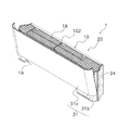
図4は、ケーシングへ装着される直前の側面部材の斜視図である。図4において、側面部材24は、ケーシング10の側方を覆うように取り付けられており、ケーシング10の側面視における外観を担っている。さらに、側面部材24は、積層構造を有しており、外側には意匠性を重視した第1層部241が配置され、内側には第1層部241を支える第2層部242が配置されている。第1層部241はアルミニウム合金製であり、第2層部242はABS樹脂製である。なお、第1層部241の材質は、アルミニウム合金に限られているものではなく、ステンレスなど他の金属であってもよい。本実施形態では、アルミニウム合金が軽くて耐食性があり長期使用に適しているので、第1層部241の材料として採用している。
(Side member 24)
FIG. 4 is a perspective view of the side member immediately before being attached to the casing. In FIG. 4, the
側面部材24は本体20の据付面に対して垂直ではなく、特に、第2層部242は、水平方向の断面が略S字状の湾曲した形状を成し、前方端から外側に張り出すように湾曲する前方湾曲面242aと前方湾曲面242aの終端から後方端に向かって内側に入り込むように湾曲する後方湾曲面(図示せず)を有している。
The
第1層部241は、第2層部242全面に張り合わされておらず、第2層部242の後方端から前方湾曲面242aの最大張り出し部分までの範囲で張り合わされている。なお、第2層部242の後方端とは、本体20の据付面に近い側の端であり、その反対側の端が前方端である。
The
(ケーシング10と側面部材24との取付構造)
また、第2層部242の前方端近傍にはネジ止め部242bが設けられており、そのネジ止め部242bには本体20の奥行方向に向ってネジ90が通る貫通穴があけられている。さらに、第2層部242の後方端には爪部242cが設けられている。
(Mounting structure of
Further, a screwing
一方、ケーシング10の側端部の前方には、側面部材24のネジ止め部242bと対応する位置に取付部10dが設けられている。取付部10dには、本体20の奥行方向に向ってネジ90が螺合するネジ穴があけられている。さらに、ケーシング10の側端部の後方には、第2層部242の爪部242cが引っ掛かる穴部10cが設けられている。
On the other hand, a mounting
側面部材24は、爪部242cと穴部10cとの接触点を支点にして回転したとき、ネジ止め部242bの貫通穴とケーシング10側の取付部10dのネジ穴とが合う位置で停止する。この取付構造によって、作業者は側面部材24の爪部242cをヒンジにしてケーシング10に当たるまで回転させるだけで、側面部材24をケーシング10に自然に位置決めしてネジ止めすることができる。側面部材24のネジ止め部242bはケーシング10の取付部10dに対して、本体20の奥行方向に向ってネジ止めされるので、自然に前後方向の位置ずれが解消され、側面部材24とケーシング10との境目が綺麗になる。
When the
逆に作業者が側面部材24をケーシング10から取り外すときは、作業者はネジ90を外してから側面部材24の爪部242cをヒンジにして外側へ回転させて爪部242cをケーシング10の穴部10cから引き抜くだけである。
Conversely, when the operator removes the
このように、側面部材24は、ケーシング10に着脱自在な取付構造によって取り付けられるので、例えば、空調室内機の移設によって配管引き出し用の穴が不要になった場合は、穴があけられる前と同等の側面部材24に取り替えることができる。その結果、従来のようなケーシング10のコーナー部に穴が残る状態、或は穴を解消する処置を行った痕跡が残る状態が回避されるので、意匠性が低下することはない。
Thus, since the
(可動パネル31)
図1及び図2において、可動パネル31は、平坦な形状を成す正面部31aと、正面部31aの両端から後方に連続して形成される側面部31bとによって、独特の意匠を創り出している。なお、正面部31aと側面部31bとは一体的に形成される。正面部31aは、ケーシング10の前面部101の全部を覆い、側面部31bは、側面部材24の前半分を覆う。
(Movable panel 31)
1 and 2, the
図1に示すように、空調室内機1が運転を停止しているときは、空調室内機1の前面外観を可動パネル31の正面部31aが担う。また、可動パネル31の側面部31bは、側面部材24の前方湾曲面242aの前方半分を覆うので、側面外観を可動パネル31の側面部31bと側面部材24の第1層部241とが担う。つまり、運転停止状態の空調室内機1の外郭は、可動パネル31の正面部31aと、可動パネル31の側面部31bと、側面部材24の第1層部241と、ケーシング10の上面部102と、ケーシング10の下面部103によって構成される。
As shown in FIG. 1, when the air conditioning
<特徴>
(1)
以上のように、側面部材24は、爪部242cと穴部10cとの接触点を支点にして回転したとき、ネジ止め部242bの貫通穴とケーシング10側の取付部10dのネジ穴とが合う位置で停止する構造であるので、側面部材24は、ケーシング10に着脱自在である。それゆえ、空調室内機の移設等によって前に加工した配管引き出し用の穴が不要になった場合は、穴があけられる前と同等の側面部材24に取り替えることができる。
<Features>
(1)
As described above, when the
(2)
据付作業者は、側面部材24のネジ止め部242bをケーシング10の取付部10dに対して、本体20の奥行方向に向ってネジ止めすることができるので、自然に前後方向の位置が決まり、側面部材24とケーシング10との境目が綺麗になる。
(2)
Since the installation operator can screw the screwing
<他の実施形態>
上記実施形態では、側面部材24が金属製の第1層部241と樹脂製の第2層部242との2層構造であるので、第1層部241によって使用者の美感への訴求力は高くなる。しかし、据付作業者とっては、側面部材24に配管引き出し用の貫通穴をあけるときの穴あけ作業が困難になる可能性が高い。そこで、側面部材24の形態として、配管が通るための貫通穴24aを有する第1形態と、貫通穴24aを有しない第2形態とを揃えることを出願人は提案している。
<Other embodiments>
In the said embodiment, since the
図5は側面部材の第1形態の斜視図であり、図6は側面部材の第2形態の斜視図である。据付作業者は、空調室内機の据付時に、第1形態および第2形態の側面部材24の両方を事前に準備しておくことができるので、側方から配管を引き出す場合は第1形態の側面部材24を使用し、側方から配管を引き出す必要がない場合は第2形態の側面部材24を使用することができる。そのようにすることによって、側面の意匠性が損なわれることがない。また、作業者は、側面部材24に貫通穴24aをあける必要がなく、作業性がよい。
FIG. 5 is a perspective view of the first form of the side member, and FIG. 6 is a perspective view of the second form of the side member. Since the installation worker can prepare both the first and
但し、側方からの配管引き出しが不可能な据付条件も有り得るので、ケーシング10の下面部103は樹脂部材であるのが好ましい。なぜなら、据付現場での穴あけが可能であり据付作業者にとって使い勝手がよいためである。
However, since there may be installation conditions in which piping cannot be pulled out from the side, the
また、側面部材24の第1形態および第2形態それぞれに別個の金型を製作することは、合理的ではないので、側面部材24を成形する金型が、第1形態の貫通穴24aに対応する位置に入れ子が組み込まれるための入れ子固定部を備えていることが好ましい。
In addition, since it is not rational to manufacture separate molds for the first and second forms of the
図7(a)は、側面部材の第1形態に対応する第2層部の樹脂成形金型の部分断面図であり、(b)は、側面部材の第2形態に対応する第2層部の樹脂成形金型の部分断面図である。図7(a)及び(b)において、金型300は、第1形態および第2形態の双方に共通の樹脂成形金型である。金型300は、第1入れ子401および第2入れ子402のいずれでも組み込まれることが可能な入れ子固定部301を備えている。
Fig.7 (a) is a fragmentary sectional view of the resin molding die of the 2nd layer part corresponding to the 1st form of a side member, (b) is the 2nd layer part corresponding to the 2nd form of a side member. It is a fragmentary sectional view of this resin molding die. 7A and 7B, a
図7(a)に示すように、第1入れ子401は貫通穴24aを形成するためのピン部401aを有している。また、図7(b)に示すように、第2入れ子402には、第1入れ子401のようなピン部は存在しない。そのため、入れ子固定部301に第1入れ子401が固定された金型で成形された第2層部242は、側面部材24の第1形態に使用され、入れ子固定部301に第2入れ子402が固定された金型で成形された第2層部242は、側面部材24の第2形態に使用される。
As shown in FIG. 7A, the
また、図8(a)は、側面部材の第1形態に対応する第1層部のプレス金型の部分断面図であり、(b)は、側面部材の第2形態に対応する第1層部のプレス金型の部分断面図である。図8(a)及び(b)において、金型350は、第1形態および第2形態の双方に共通のプレス金型である。金型350は、第1入れ子451および第2入れ子452のいずれでも組み込まれることが可能な入れ子固定部351を備えている。
Moreover, Fig.8 (a) is a fragmentary sectional view of the press die of the 1st layer part corresponding to the 1st form of a side member, (b) is the 1st layer corresponding to the 2nd form of a side member. It is a fragmentary sectional view of the press die of a part. 8A and 8B, a
図8(a)に示すように、第1入れ子451は貫通穴24aを形成するためのピン部451aを有している。また、図8(b)に示すように、第2入れ子452には、第1入れ子451のようなピン部は存在しない。そのため、入れ子固定部351に第1入れ子451が固定された金型で成形された第1層部241は、側面部材24の第1形態に使用され、入れ子固定部351に第2入れ子452が固定された金型で成形された第1層部241は、側面部材24の第2形態に使用される。このため、側面部材の形態ごとに金型を備える場合と比べて金型費用が低く抑えられる。
As shown to Fig.8 (a), the 1st nest | insert 451 has the
以上のように、本発明によれば、配管が本体の側方から引き出される機器であって、移設工事などによって前の配管引き回し跡が人目に付くことを避けたい場合に有用である。 As described above, according to the present invention, the pipe is drawn out from the side of the main body, which is useful when it is desired to avoid the previous trace of the pipe from being noticed by the transfer work or the like.
10 ケーシング
10c 穴部
10d 取付部
20 本体
24 側面部材
24a 貫通穴
90 ネジ
102 上面部
103 下面部
241 第1層部
242 第2層部
242a 前方湾曲部
242b ネジ止め部
242c 爪部
300 金型
301 入れ子固定部
401 第1入れ子
402 第2入れ子
DESCRIPTION OF
Claims (7)
本体ケーシング(10)と、
前方端から外側に張り出すように湾曲する前方湾曲面(242a)と前記前方湾曲面(242a)の終端から後方端に向かって内側に入り込むように湾曲する後方湾曲面を有し、前記本体ケーシング(10)の側面視における外観を担う側面部材(24)と、
平坦な形状を成す正面部(31a)と前記正面部(31a)の両端から後方に連続して一体的に形成される側面部(31b)を有する可動パネル(31)と、
を備え、
前記側面部材(24)は、前記本体ケーシング(10)に着脱自在な取付構造によって前記本体ケーシング(10)の側方を覆うように取り付けられ、
前記正面部(31a)は、前記本体ケーシング(10)の前面部101の全部を覆い、
前記側面部(31b)は、前記前方湾曲面(242a)に沿って前記側面部材(24)の前半分を覆う、
空調室内機。 An air conditioning indoor unit in which piping can be drawn from the side of the main body (20),
A body casing (10);
A front curved surface (242a) that curves so as to project outward from the front end; A side member (24) that bears the appearance of the side view of (10);
A movable panel (31) having a flat front portion (31a) and a side portion (31b) integrally formed continuously from both ends of the front portion (31a) rearwardly;
With
The side member (24) is attached so as to cover the side of the main casing (10) by a detachable mounting structure to the main casing (10),
The front part (31a) covers the entire front part 101 of the main casing (10),
The side surface portion (31b) covers the front half of the side surface member (24) along the front curved surface (242a) .
Air conditioning indoor unit.
前記本体ケーシング(10)の側方のうち前記配管が引き出される側には、前記配管が通るための貫通穴(24a)を有する第1形態が採用され、
前記本体ケーシング(10)の側方のうち前記配管が引き出されない側には、前記貫通穴(24a)を有しない第2形態が採用される、
請求項1に記載の空調室内機。 As a form of the side member (24),
The first form having a through hole (24a) through which the pipe passes is adopted on the side from which the pipe is drawn out of the side of the main casing (10).
On the side where the pipe is not drawn out of the side of the main casing (10), a second form not having the through hole (24a) is adopted.
The air conditioning indoor unit according to claim 1.
請求項1に記載の空調室内機。 The side member (24) has a two-layer structure of a metal part (241) and a resin part (242).
The air conditioning indoor unit according to claim 1.
少なくとも前記下面部(103)が樹脂部材である、
請求項2に記載の空調室内機。 The main casing (10) has an upper surface (102) and a lower surface (103),
At least the lower surface (103) is a resin member,
The air conditioning indoor unit according to claim 2.
前記本体ケーシング(10)に取り付けられたとき前記本体(20)の据付面に対して垂直ではない面(242a)と、
前記面(242a)に形成されるネジ止め部(242b)と、
を有し、
前記ネジ止め部(242b)が、前記本体ケーシング(10)に前記本体(20)の奥行方向に向ってネジ止めされる、
請求項1に記載の空調室内機。 The side member (24)
A surface (242a) that is not perpendicular to the installation surface of the body (20) when attached to the body casing (10);
A screwing portion (242b) formed on the surface (242a);
Have
The screwing portion (242b) is screwed to the main body casing (10) in the depth direction of the main body (20).
The air conditioning indoor unit according to claim 1.
前記ネジ止め部(242b)と、
前記側面部材(24)の端部のうち前記ネジ止め部(242b)から遠い側の端部に設けられる爪部(242c)と、
前記本体ケーシング(10)に設けられ、前記爪部(242c)が引っ掛かる穴部(10c)と、
前記本体ケーシング(10)に設けられ、前記ネジ止め部(242b)を通るネジ(90)が螺合する取付部(10d)と、
を含み、
前記側面部材(24)は、前記爪部(242c)と前記穴部(10c)との接触点を支点にして回転したとき、前記ネジ止め部(242b)と前記取付部(10d)とが合う位置で停止して位置決めされる、
請求項5に記載の空調室内機。 The mounting structure of the side member (24) is:
The screwing portion (242b);
A claw portion (242c) provided at an end portion far from the screwing portion (242b) among the end portions of the side surface member (24);
A hole (10c) provided in the main body casing (10), to which the claw portion (242c) is caught;
An attachment portion (10d) provided in the main body casing (10) and into which a screw (90) passing through the screw fastening portion (242b) is screwed;
Including
When the side member (24) rotates with the contact point between the claw portion (242c) and the hole portion (10c) as a fulcrum, the screwing portion (242b) and the mounting portion (10d) are aligned. Positioned at a stop,
The air conditioning indoor unit according to claim 5.
前記側面部材(24)を成形する金型(300)は、前記第1形態の前記貫通穴(24a)に対応する位置に入れ子が組み込まれるための入れ子固定部(301)を備え、
前記側面部材(24)の前記第1形態が製造されるとき、前記貫通穴(24a)が形成されるための第1入れ子(401)が前記入れ子固定部(301)に組み込まれ、
前記側面部材(24)の前記第2形態が製造されるとき、前記貫通穴(24a)が形成されないための第2入れ子(402)が前記入れ子固定部(301)に組み込まれる、
空調室内機の製造方法。 It is a manufacturing method of the air-conditioning indoor unit of Claim 2,
The mold (300) for molding the side member (24) includes a nesting fixing part (301) for inserting a nesting at a position corresponding to the through hole (24a) of the first form,
When the first form of the side member (24) is manufactured, a first insert (401) for forming the through hole (24a) is incorporated in the insert fixing portion (301),
When the second form of the side member (24) is manufactured, a second insert (402) for not forming the through hole (24a) is incorporated in the insert fixing part (301).
Manufacturing method of air conditioning indoor unit.
Priority Applications (1)
| Application Number | Priority Date | Filing Date | Title |
|---|---|---|---|
| JP2010012199A JP5593708B2 (en) | 2010-01-22 | 2010-01-22 | Air conditioning indoor unit |
Applications Claiming Priority (1)
| Application Number | Priority Date | Filing Date | Title |
|---|---|---|---|
| JP2010012199A JP5593708B2 (en) | 2010-01-22 | 2010-01-22 | Air conditioning indoor unit |
Publications (2)
| Publication Number | Publication Date |
|---|---|
| JP2011149649A JP2011149649A (en) | 2011-08-04 |
| JP5593708B2 true JP5593708B2 (en) | 2014-09-24 |
Family
ID=44536794
Family Applications (1)
| Application Number | Title | Priority Date | Filing Date |
|---|---|---|---|
| JP2010012199A Active JP5593708B2 (en) | 2010-01-22 | 2010-01-22 | Air conditioning indoor unit |
Country Status (1)
| Country | Link |
|---|---|
| JP (1) | JP5593708B2 (en) |
Families Citing this family (4)
| Publication number | Priority date | Publication date | Assignee | Title |
|---|---|---|---|---|
| JP6236738B2 (en) * | 2013-08-23 | 2017-11-29 | 株式会社ノーリツ | Water heater |
| JP2017133795A (en) * | 2016-01-29 | 2017-08-03 | 株式会社富士通ゼネラル | Air conditioner |
| CN107532818B (en) | 2016-02-08 | 2020-03-06 | 三菱电机株式会社 | Indoor unit of air conditioner |
| JP6725345B2 (en) * | 2016-07-07 | 2020-07-15 | シャープ株式会社 | Blower |
Family Cites Families (11)
| Publication number | Priority date | Publication date | Assignee | Title |
|---|---|---|---|---|
| JPS5045941U (en) * | 1973-08-22 | 1975-05-08 | ||
| JPS579620Y2 (en) * | 1977-11-07 | 1982-02-24 | ||
| JPS5940729U (en) * | 1982-09-08 | 1984-03-15 | 株式会社富士通ゼネラル | air conditioner |
| JPH0615233Y2 (en) * | 1988-07-08 | 1994-04-20 | 三洋電機株式会社 | Indoor unit of separation type air conditioner |
| JP3632538B2 (en) * | 1999-12-27 | 2005-03-23 | 三菱電機株式会社 | vehicle |
| JP2002081698A (en) * | 2000-06-21 | 2002-03-22 | Yuuki:Kk | Header unit used for both cooling and heating |
| JP2002054821A (en) * | 2000-08-08 | 2002-02-20 | Mitsubishi Electric Corp | Air conditioner |
| AU2002314573A1 (en) * | 2001-06-19 | 2003-01-02 | Lg Electronics Inc. | Air conditioner |
| JP4624174B2 (en) * | 2004-08-27 | 2011-02-02 | 三洋電機株式会社 | Air conditioner |
| JP4381943B2 (en) * | 2004-09-28 | 2009-12-09 | 三菱電機株式会社 | Air conditioner |
| JP4059267B2 (en) * | 2005-11-30 | 2008-03-12 | ダイキン工業株式会社 | Air conditioner indoor unit |
-
2010
- 2010-01-22 JP JP2010012199A patent/JP5593708B2/en active Active
Also Published As
| Publication number | Publication date |
|---|---|
| JP2011149649A (en) | 2011-08-04 |
Similar Documents
| Publication | Publication Date | Title |
|---|---|---|
| JP4380744B2 (en) | Blower unit | |
| JP6238851B2 (en) | Air conditioner outdoor unit | |
| JP5593708B2 (en) | Air conditioning indoor unit | |
| JP5110095B2 (en) | Air conditioning indoor unit panel | |
| JP5537872B2 (en) | Wall-mounted air conditioner | |
| AU2015405043B2 (en) | Indoor unit of air conditioners | |
| AU2006333872B8 (en) | Indoor unit of air conditioner | |
| JP5631091B2 (en) | Air conditioner | |
| JP3071353B2 (en) | Indoor unit of air conditioner | |
| JP6207479B2 (en) | Indoor unit for air conditioner and method for manufacturing indoor unit for air conditioner | |
| JP6633457B2 (en) | Air conditioner | |
| JP2014145499A (en) | Wind direction change device and air conditioning device with the same | |
| JP6727401B2 (en) | Air conditioner indoor unit | |
| JP5465021B2 (en) | Turbo fan and air conditioner equipped with the turbo fan | |
| JP2008215687A (en) | Air conditioner | |
| JP2006300361A (en) | Air conditioner | |
| CN101178248A (en) | Heat converter fixed structure of split wall hanging type indoor set of air-conditioner | |
| JP4510172B2 (en) | Cross flow fan | |
| JP2004239601A (en) | Wall mounted type air conditioner | |
| JP4857794B2 (en) | Air conditioner indoor unit | |
| JP3992062B2 (en) | Indoor unit of air conditioner and cover member thereof, and wall embedding method of indoor unit | |
| JP5984742B2 (en) | Air conditioner indoor unit | |
| WO2018025302A1 (en) | Indoor unit for air conditioner | |
| JP2010048470A (en) | Air conditioner | |
| JP5337738B2 (en) | Air conditioner |
Legal Events
| Date | Code | Title | Description |
|---|---|---|---|
| A621 | Written request for application examination |
Free format text: JAPANESE INTERMEDIATE CODE: A621 Effective date: 20121005 |
|
| A977 | Report on retrieval |
Free format text: JAPANESE INTERMEDIATE CODE: A971007 Effective date: 20130808 |
|
| A131 | Notification of reasons for refusal |
Free format text: JAPANESE INTERMEDIATE CODE: A131 Effective date: 20130813 |
|
| A521 | Written amendment |
Free format text: JAPANESE INTERMEDIATE CODE: A523 Effective date: 20130927 |
|
| A02 | Decision of refusal |
Free format text: JAPANESE INTERMEDIATE CODE: A02 Effective date: 20140212 |
|
| A521 | Written amendment |
Free format text: JAPANESE INTERMEDIATE CODE: A523 Effective date: 20140507 |
|
| A911 | Transfer of reconsideration by examiner before appeal (zenchi) |
Free format text: JAPANESE INTERMEDIATE CODE: A911 Effective date: 20140514 |
|
| TRDD | Decision of grant or rejection written | ||
| A01 | Written decision to grant a patent or to grant a registration (utility model) |
Free format text: JAPANESE INTERMEDIATE CODE: A01 Effective date: 20140708 |
|
| A61 | First payment of annual fees (during grant procedure) |
Free format text: JAPANESE INTERMEDIATE CODE: A61 Effective date: 20140721 |
|
| R151 | Written notification of patent or utility model registration |
Ref document number: 5593708 Country of ref document: JP Free format text: JAPANESE INTERMEDIATE CODE: R151 |