JP5592948B2 - Touch and hover detection - Google Patents
Touch and hover detection Download PDFInfo
- Publication number
- JP5592948B2 JP5592948B2 JP2012519733A JP2012519733A JP5592948B2 JP 5592948 B2 JP5592948 B2 JP 5592948B2 JP 2012519733 A JP2012519733 A JP 2012519733A JP 2012519733 A JP2012519733 A JP 2012519733A JP 5592948 B2 JP5592948 B2 JP 5592948B2
- Authority
- JP
- Japan
- Prior art keywords
- hover
- touch
- sensor array
- signal
- control system
- Prior art date
- Legal status (The legal status is an assumption and is not a legal conclusion. Google has not performed a legal analysis and makes no representation as to the accuracy of the status listed.)
- Expired - Fee Related
Links
Images


Classifications
-
- G—PHYSICS
- G06—COMPUTING; CALCULATING OR COUNTING
- G06F—ELECTRIC DIGITAL DATA PROCESSING
- G06F3/00—Input arrangements for transferring data to be processed into a form capable of being handled by the computer; Output arrangements for transferring data from processing unit to output unit, e.g. interface arrangements
- G06F3/01—Input arrangements or combined input and output arrangements for interaction between user and computer
- G06F3/03—Arrangements for converting the position or the displacement of a member into a coded form
- G06F3/041—Digitisers, e.g. for touch screens or touch pads, characterised by the transducing means
- G06F3/0416—Control or interface arrangements specially adapted for digitisers
- G06F3/04166—Details of scanning methods, e.g. sampling time, grouping of sub areas or time sharing with display driving
- G06F3/041662—Details of scanning methods, e.g. sampling time, grouping of sub areas or time sharing with display driving using alternate mutual and self-capacitive scanning
-
- G—PHYSICS
- G06—COMPUTING; CALCULATING OR COUNTING
- G06F—ELECTRIC DIGITAL DATA PROCESSING
- G06F3/00—Input arrangements for transferring data to be processed into a form capable of being handled by the computer; Output arrangements for transferring data from processing unit to output unit, e.g. interface arrangements
- G06F3/01—Input arrangements or combined input and output arrangements for interaction between user and computer
- G06F3/03—Arrangements for converting the position or the displacement of a member into a coded form
- G06F3/041—Digitisers, e.g. for touch screens or touch pads, characterised by the transducing means
- G06F3/044—Digitisers, e.g. for touch screens or touch pads, characterised by the transducing means by capacitive means
- G06F3/0446—Digitisers, e.g. for touch screens or touch pads, characterised by the transducing means by capacitive means using a grid-like structure of electrodes in at least two directions, e.g. using row and column electrodes
-
- G—PHYSICS
- G06—COMPUTING; CALCULATING OR COUNTING
- G06F—ELECTRIC DIGITAL DATA PROCESSING
- G06F3/00—Input arrangements for transferring data to be processed into a form capable of being handled by the computer; Output arrangements for transferring data from processing unit to output unit, e.g. interface arrangements
- G06F3/01—Input arrangements or combined input and output arrangements for interaction between user and computer
- G06F3/048—Interaction techniques based on graphical user interfaces [GUI]
- G06F3/0481—Interaction techniques based on graphical user interfaces [GUI] based on specific properties of the displayed interaction object or a metaphor-based environment, e.g. interaction with desktop elements like windows or icons, or assisted by a cursor's changing behaviour or appearance
- G06F3/04817—Interaction techniques based on graphical user interfaces [GUI] based on specific properties of the displayed interaction object or a metaphor-based environment, e.g. interaction with desktop elements like windows or icons, or assisted by a cursor's changing behaviour or appearance using icons
-
- G—PHYSICS
- G06—COMPUTING; CALCULATING OR COUNTING
- G06F—ELECTRIC DIGITAL DATA PROCESSING
- G06F3/00—Input arrangements for transferring data to be processed into a form capable of being handled by the computer; Output arrangements for transferring data from processing unit to output unit, e.g. interface arrangements
- G06F3/01—Input arrangements or combined input and output arrangements for interaction between user and computer
- G06F3/048—Interaction techniques based on graphical user interfaces [GUI]
- G06F3/0484—Interaction techniques based on graphical user interfaces [GUI] for the control of specific functions or operations, e.g. selecting or manipulating an object, an image or a displayed text element, setting a parameter value or selecting a range
- G06F3/04845—Interaction techniques based on graphical user interfaces [GUI] for the control of specific functions or operations, e.g. selecting or manipulating an object, an image or a displayed text element, setting a parameter value or selecting a range for image manipulation, e.g. dragging, rotation, expansion or change of colour
-
- G—PHYSICS
- G06—COMPUTING; CALCULATING OR COUNTING
- G06F—ELECTRIC DIGITAL DATA PROCESSING
- G06F3/00—Input arrangements for transferring data to be processed into a form capable of being handled by the computer; Output arrangements for transferring data from processing unit to output unit, e.g. interface arrangements
- G06F3/01—Input arrangements or combined input and output arrangements for interaction between user and computer
- G06F3/048—Interaction techniques based on graphical user interfaces [GUI]
- G06F3/0484—Interaction techniques based on graphical user interfaces [GUI] for the control of specific functions or operations, e.g. selecting or manipulating an object, an image or a displayed text element, setting a parameter value or selecting a range
- G06F3/0486—Drag-and-drop
-
- G—PHYSICS
- G06—COMPUTING; CALCULATING OR COUNTING
- G06F—ELECTRIC DIGITAL DATA PROCESSING
- G06F2203/00—Indexing scheme relating to G06F3/00 - G06F3/048
- G06F2203/041—Indexing scheme relating to G06F3/041 - G06F3/045
- G06F2203/04101—2.5D-digitiser, i.e. digitiser detecting the X/Y position of the input means, finger or stylus, also when it does not touch, but is proximate to the digitiser's interaction surface and also measures the distance of the input means within a short range in the Z direction, possibly with a separate measurement setup
-
- G—PHYSICS
- G06—COMPUTING; CALCULATING OR COUNTING
- G06F—ELECTRIC DIGITAL DATA PROCESSING
- G06F2203/00—Indexing scheme relating to G06F3/00 - G06F3/048
- G06F2203/041—Indexing scheme relating to G06F3/041 - G06F3/045
- G06F2203/04107—Shielding in digitiser, i.e. guard or shielding arrangements, mostly for capacitive touchscreens, e.g. driven shields, driven grounds
Description
本発明は、一般的に、タッチ及びホバー(hover)感知に係り、より詳細には、改良された容量性のタッチ及びホバー感知に係る。 The present invention relates generally to touch and hover sensing, and more particularly to improved capacitive touch and hover sensing.
コンピューティングシステムの操作を行うために、ボタン又はキー、マウス、トラックボール、ジョイスティック、タッチセンサパネル、タッチスクリーン、等の多数の形式の入力装置を現在利用することができる。特に、タッチスクリーンは、操作が容易で且つ多様性があると共に、価格も下がっていることから、益々普及してきている。タッチスクリーンは、液晶ディスプレイ(LCD)のようなディスプレイ装置の前方に配置された透明なタッチセンサパネル、又はタッチ感知回路がディスプレイに部分的又は完全に一体化された一体型タッチスクリーン、等を含むことができる。タッチスクリーンは、ディスプレイ装置に表示されているユーザインターフェイス(UI)によって指令される位置に指、スタイラス又は他の物体を使用してユーザがタッチスクリーンにタッチすることによって種々の機能を遂行できるようにする。一般的に、タッチスクリーンは、タッチセンサパネルにおけるタッチ事象及びタッチ事象の位置を認識し、次いで、コンピューティングシステムが、タッチ事象の時間に現れる表示に従ってタッチ事象を解釈し、その後、タッチ事象に基づいて1つ以上のアクションを遂行することができる。 Numerous types of input devices such as buttons or keys, mice, trackballs, joysticks, touch sensor panels, touch screens, etc., are currently available for performing computing system operations. In particular, touch screens are becoming more and more popular because they are easy to operate and diverse, and the price is low. The touch screen includes a transparent touch sensor panel disposed in front of a display device such as a liquid crystal display (LCD), an integrated touch screen in which touch sensing circuits are partially or fully integrated with the display, and the like. be able to. The touch screen allows the user to perform various functions by touching the touch screen using a finger, stylus or other object at a position commanded by a user interface (UI) displayed on the display device. To do. In general, the touch screen recognizes the touch event on the touch sensor panel and the location of the touch event, and then the computing system interprets the touch event according to the display that appears at the time of the touch event, and then based on the touch event Can perform one or more actions.
相互キャパシタンスタッチセンサパネルは、実質的に透明な基板上に水平及び垂直方向の行及び列にしばしば配列されるインジウムスズ酸化物(ITO)のような実質的に透明な導電性材料のドライブ線及びセンス線のマトリクスから形成することができる。ドライブ線を通してドライブ信号を送信し、ドライブ線とセンス線の交差点又は隣接領域(センスピクセル)において静的相互キャパシタンスを測定することができる。静的相互キャパシタンス、及びタッチ事象による静的相互キャパシタンスの変化は、ドライブ信号によりセンス線に発生できるセンス信号から決定することができる。 A mutual capacitance touch sensor panel comprises drive lines of substantially transparent conductive material, such as indium tin oxide (ITO), often arranged in horizontal and vertical rows and columns on a substantially transparent substrate. It can be formed from a matrix of sense lines. A drive signal can be transmitted through the drive line and the static mutual capacitance can be measured at the intersection of the drive line and the sense line or at an adjacent region (sense pixel). The static mutual capacitance and the change in static mutual capacitance due to the touch event can be determined from the sense signal that can be generated on the sense line by the drive signal.
あるタッチセンサは、ホバー事象、即ち物体がタッチセンサの近くにあるがそれにタッチしない事象、も検出できるが、例えば、ホバー検出範囲が限定され、ホバー情報の収集が不充分である、等のために、典型的なホバー検出情報は、実用性が限定される。 Some touch sensors can also detect hover events, i.e. objects that are close to the touch sensor but do not touch it, but for example because the hover detection range is limited and the collection of hover information is insufficient. In addition, the usefulness of typical hover detection information is limited.
本発明は、改良された容量性のタッチ及びホバー(hover)感知に係る。容量性センサアレイは、交流(AC)信号のような電気的信号で駆動されて、センサアレイからタッチ面を通して外方に延びる電界を発生し、例えば、タッチ面へのタッチ、又はタッチスクリーン装置のタッチ面上での物体のホバリング(hovering)を検出することができる。又、電界は、タッチ面から逆方向にセンサアレイの後方にも延び、これは、典型的にタッチスクリーン装置の内部スペースである。センサアレイのホバー感知能力を向上させるためにAC接地シールドを使用することができる。このAC接地シールドは、センサアレイの後方に配置され、センサアレイを駆動する信号と同じ波形を有する信号で刺激することができる。その結果、センサアレイから外方に延びる電界を集中させることができる。このようにして、例えば、センサアレイのホバー感知能力を改善することができる。 The present invention relates to improved capacitive touch and hover sensing. A capacitive sensor array is driven with an electrical signal, such as an alternating current (AC) signal, to generate an electric field extending outwardly from the sensor array through the touch surface, eg, touching the touch surface or touch screen device It is possible to detect hovering of an object on the touch surface. The electric field also extends backward from the touch surface to the back of the sensor array, which is typically the internal space of the touch screen device. An AC ground shield can be used to improve the hover sensing capability of the sensor array. This AC ground shield is placed behind the sensor array and can be stimulated with a signal having the same waveform as the signal driving the sensor array. As a result, the electric field extending outward from the sensor array can be concentrated. In this way, for example, the hover sensing capability of the sensor array can be improved.
又、タッチ面の真上のスペースの外側で物体のホバー位置を検出するための方法を使用してホバー感知を改善することもできる。特に、例えば、タッチスクリーンの端の境界エリアにおいて、タッチ面の近傍であるが、その真上ではない物体(換言すれば、タッチ面の真上のスペースの外側の物体)のホバー位置及び/又は高さは、タッチスクリーンの端付近のセンサの測定値を使用して、その測定値をモデルに適合させることにより、決定することができる。他の改善は、タッチ及びホバー感知の共同動作に係り、例えば、タッチ感知、ホバー感知、タッチ及びホバーの両感知をいつ、どのように行うか、或いはそのどちらも行わないかを決定することに係る。 It is also possible to improve hover sensing using a method for detecting the hover position of an object outside the space directly above the touch surface. In particular, for example, in the boundary area of the edge of the touch screen, the hover position of an object that is near the touch surface but not directly above it (in other words, an object outside the space directly above the touch surface) and / or The height can be determined by using sensor readings near the edge of the touch screen and fitting the measurements to the model. Other improvements relate to the joint operation of touch and hover sensing, for example, determining when and how to perform touch sensing, hover sensing, touch and hover sensing, or neither. Related.
本開示は、1つ以上の種々の実施形態に基づき添付図面を参照して詳細に述べる。添付図面は、本発明の実施形態を単に例示するものに過ぎない。又、添付図面は、本発明の理解を容易にするためにもので、本発明をそれに限定するものではない。又、図示を明瞭にし、容易にするために、添付図面は、必ずしも一定の縮尺率で描かれていないことに注意されたい。 The present disclosure will be described in detail based on one or more various embodiments and with reference to the accompanying drawings. The accompanying drawings are merely illustrative of embodiments of the invention. Further, the accompanying drawings are provided for facilitating understanding of the present invention, and the present invention is not limited thereto. It should also be noted that the attached drawings are not necessarily drawn to scale for clarity and ease of illustration.
実施形態の以下の説明において、その一部分を形成し且つ本発明の特定実施形態を一例として示す添付図面を参照する。他の実施形態も使用できると共に、本発明の実施形態の範囲から逸脱せずに構造上の変更もできることを理解されたい。 In the following description of the embodiments, reference is made to the accompanying drawings that form a part hereof, and in which are shown by way of illustration specific embodiments of the invention. It should be understood that other embodiments may be used and structural changes may be made without departing from the scope of the embodiments of the present invention.
本発明は、一般的に、タッチ及びホバー(hover)感知に係り、より詳細には、改良された容量性のタッチ及びホバー感知に係る。例えば、容量性タッチセンサアレイのようなセンサアレイのホバー感知能力を向上させるために、交流(AC)接地シールドが使用される。タッチスクリーンの容量性タッチセンサアレイへ送信されるAC信号のような電気的信号は、タッチ面へのタッチ又はタッチ面上でホバリングしている物体を検出するためにセンサアレイからタッチ面を通して外方へ延びる電界を発生する。この電界は、タッチ面から逆方向にセンサアレイの後方にも延び、これは、典型的にタッチスクリーン装置の内部スペースである。センサアレイの後方にAC接地シールドを配置することができ、このAC接地シールドは、例えば、AC信号と同じ波形を有する信号で刺激することができる。その結果、センサアレイから外方に延びる電界を、以下に詳細に述べるように、集中させることができる。このようにして、例えば、センサアレイのホバー感知能力を改善することができる。 The present invention relates generally to touch and hover sensing, and more particularly to improved capacitive touch and hover sensing. For example, an alternating current (AC) ground shield is used to improve the hover sensing capability of a sensor array, such as a capacitive touch sensor array. An electrical signal, such as an AC signal, transmitted to the capacitive touch sensor array of the touch screen is transmitted outward from the sensor array through the touch surface to detect a touch on the touch surface or an object hovering on the touch surface. An electric field extending to is generated. This electric field also extends backwards from the touch surface to the back of the sensor array, which is typically the internal space of the touch screen device. An AC ground shield can be placed behind the sensor array, and this AC ground shield can be stimulated with a signal having the same waveform as the AC signal, for example. As a result, the electric field extending outward from the sensor array can be concentrated as described in detail below. In this way, for example, the hover sensing capability of the sensor array can be improved.
又、ホバー感知は、タッチ面の真上のスペースの外側で物体のホバー位置を検出するための方法を使用して改善することもできる。特に、例えば、タッチスクリーンの端の境界エリアにおいて、タッチ面の近傍であるが、その真上ではない物体(換言すれば、タッチ面の真上のスペースの外側の物体)のホバー位置及び/又は高さは、以下に詳細に述べるように、タッチスクリーンの端付近のセンサの測定値を使用して、その測定値をモデルに適合させることで、決定することができる。他の改善は、タッチ及びホバー感知の共同動作に係り、例えば、以下に詳細に述べるように、タッチ感知、ホバー感知、タッチ及びホバーの両感知をいつ、どのように行うか、或いはそのどちらも行わないかを決定することに係る。 Hover sensing can also be improved using a method for detecting the hover position of an object outside the space directly above the touch surface. In particular, for example, in the boundary area of the edge of the touch screen, the hover position of an object that is near the touch surface but not directly above it (in other words, an object outside the space directly above the touch surface) and / or The height can be determined by using sensor measurements near the edge of the touch screen and fitting the measurements to the model, as described in detail below. Other improvements relate to the joint operation of touch and hover sensing, for example when and how to perform touch sensing, hover sensing, touch and hover sensing, as described in detail below, or both. Related to deciding not to do.
図1A及び1Bは、AC接地シールド(「被駆動シールド」とも称される)を含む容量性タッチ及びホバー感知装置の例示的実施形態を示す。 1A and 1B illustrate an exemplary embodiment of a capacitive touch and hover sensing device that includes an AC ground shield (also referred to as a “driven shield”).
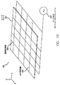
図1Aは、水平線103及び垂直線105のアレイを含むセンサアレイ101を伴うタッチ及びホバー感知装置100の一部分を示す。水平線103及び垂直線105は、例えば、自己容量性感知システムの導電線である。他の実施形態では、相互容量性、光学的、超音波、等の他の形式の感知スキームが使用される。例えば、タッチスクリーンのようなある実施形態では、線103及び/又は105は、実質的に透明な導電性材料で形成することができる。例えば、トラックパッドのようなある実施形態では、線103及び/又は105は、不透明な導電性材料で形成されてもよい。
FIG. 1A shows a portion of a touch and
タッチ及びホバー感知装置100は、水平線103及び/又は垂直線105に印加される電気的信号、例えば、AC信号でセンサアレイ101を駆動できるタッチ及びホバーコントロールシステム107も備えている。センサアレイ101へ送信されるAC信号は、センサアレイから延びる電界を形成し、これを使用して、センサアレイ付近の物体を検出することができる。例えば、センサアレイ101付近の電界に位置する物体は、センサアレイの自己キャパシタンスを変化させ、これを種々の技術で測定することができる。タッチ及びホバーコントロールシステム107は、水平線及び垂直線の各々の自己キャパシタンスを測定し、センサアレイ101上又はその付近のタッチ事象及びホバー事象を検出することができる。
The touch and hover
最大検出範囲は、種々のファクタに依存し、それらファクタは、センサアレイ101により発生される電界の強度を含み、これは、検出に使用されるAC信号の電圧、即ちその振幅に依存する。しかしながら、AC信号電圧は、種々の設計ファクタ、例えば、電力制限、インピーダンス制限、等によって制限されることがある。ある用途、例えば、一般的には消費者向け電子装置、より特定すればポータブル電子装置では、AC信号の最大電圧制限が、許容検出範囲を伴うタッチ及びホバー感知システムの設計を困難にする。
The maximum detection range depends on various factors, which include the strength of the electric field generated by the
この点に関して、図1Bは、センサアレイ101に使用されるAC接地シールドシステムを示している。このAC接地シールドシステムは、AC接地シールド201及びACシールド駆動システム203を備えている。AC接地シールド201は、実質的にセンサアレイ101の後方に配置され、即ちセンサアレイのタッチ及びホバー検出側とは逆のセンサアレイ101の側に配置される。ACシールド駆動システム203は、AC接地シールド201へAC信号を送信して、センサアレイ101によって発生される電界を集中する上で助けとなる電界を、センサアレイ101の上の検出スペースに生成することができる(図1Bにz方向として示す)。
In this regard, FIG. 1B shows an AC ground shield system used for the
図2A及び2Bは、センサアレイ101により発生される電界をAC接地シールド201によりどのようにして集中させるかの一例を示す。図2Aは、センサアレイ101の刺激される水平導電線103を、AC接地シールド201をもたない構成で示している。電界250は、水平導電線103から全ての方向に実質的に放射状に延びる。図2Bは、図2Aの構成でAC接地シールド201をどのように含ませると、導電線103の電界を、異なる電界253へと集中させることができるかを示す。図2Bにおいて、センサアレイ101の水平導電線103は、図2Aの場合と同様に刺激され、そしてAC接地シールド201は、導電線103と実質的に同様に刺激される。例えば、AC接地シールド201へ送信されるAC信号は、センサアレイ101へ送信されるAC信号と実質的に同じ波形を有し、AC接地シールドの電圧を特定の時間にセンサアレイ101の電圧と実質的に同じにすることができる。AC接地シールドを刺激すると、電界255が発生する。図2Bは、AC接地シールド201の動作により水平導電線103の上に(z方向に)集中された電界253を示している。このようにして、例えば、AC接地シールド201を追加することで、センサアレイ101の検出範囲を広げる上で助けとなる。
2A and 2B show an example of how the electric field generated by the
更に、AC接地シールド201は、センサアレイ101とAC接地シールド201との間の電界を減少又は排除することができる。より詳細には、センサアレイ101及びAC接地シールド201の電圧が時間と共に変化しても、その変化は実質的に一致して生じ、センサアレイとAC接地シールドとの間の電圧差、即ち電位を、ゼロ又は実質的にゼロに保つことができる。それ故、センサアレイ101とAC接地シールド201との間には、電界がほとんど又は全く生じない。図2Bは、例えば、この例示的構成において水平導電線103とAC接地シールド201との間のスペースに電界が実質的にないことを示している。
Further, the
図3は、センサアレイ101、タッチ及びホバーコントロールシステム107、AC接地シールド201、及びACシールド駆動システム203が、タッチスクリーン300において具現化される例示的な実施形態を示す。この例において、水平線103及び垂直線105は、実質的に透明な導体で形成された電極である。図3は、センサアレイ101及びAC接地シールド201を実質的にディスプレイ回路317と並置することができ、特に、AC接地シールドを実質的にディスプレイ回路317とセンサアレイ101との間に配置することのできるタッチスクリーン300の一部分を示す。境界301は、センサアレイ101の遠方端303を保持する。ユーザは、カバー面305を通して表示画像を見ることができ、そして例えば、指をカバー面にタッチし、及び/又はセンサアレイ101の真上のスペース307においてカバー面付近で指をホバーし、検出されるタッチ事象及び/又はホバー事象に対応するグラフィックユーザインターフェイス(GUI)の対応要素をアクチベートすることができる。この実施例では、タッチ及びホバーコントロールシステム107は、波形311を有するAC信号を伝送線309に送信し、この伝送線は、タッチ及びホバーコントロールシステムをセンサアレイ101に接続する。タッチ及びホバーコントロールシステム107は、波形311を、記憶のためにメモリ313にも送信する。メモリ313は、波形311のバッファコピー315を記憶する。ACシールド駆動システム203は、メモリ313から波形のバッファコピー315を読み取り、そして波形311を伴う対応AC信号を発生し、これは、次いで、AC接地シールド201へ送信される。この例示的構成において、センサアレイ101は、実質的にAC接地シールド201とカバー面305との間に配置され、そしてAC接地シールド201は、上述したように動作して、カバー面305の上の検出スペース307に電界を集中させる。
FIG. 3 illustrates an exemplary embodiment in which the
又、AC接地シールド201の構成は、センサアレイ101を、他の電子装置及び/又は接地ソースからシールドする上でも助けとなり、例えば、カバー面305を通して見る画像を発生するためにディスプレイドライバ319により駆動できるディスプレイ回路317からシールドする上でも助けとなる。特に、上述したように、AC接地シールド201は、センサアレイ101からAC接地シールドの方向に発生する電界を防止又は減少する上で助けとなる。図3に示す構成では、AC接地シールド201は、センサアレイ101と、他の内部電子装置、例えば、ディスプレイ回路317及びディスプレイドライバ319との間に配置することができる。それ故、AC接地シールド201は、センサアレイ101から発生してディスプレイ回路317及びディスプレイドライバ319に到達し得る電界を防止又は減少することができる。このようにして、AC接地シールド201は、センサアレイ101を、この例示的構成において他の内部電子装置から電気的に分離する上で助けとなり、これは、物体が検出スペース307にタッチし/ホバリングすることにより生じるキャパシタンス変化の正確な測定を妨げることのあるノイズ、漂遊キャパシタンス、等の望ましからぬ影響を減少する。
The configuration of the
別の形式のACシールド、即ち伝送線ACシールド308が図3に示されている。この伝送線ACシールド308は、伝送線309の一部分を実質的に取り巻く。ACシールド駆動システム203は、バッファされたコピー315を使用して、波形311をもつ信号を伝送線ACシールド308へも送信する。これは、伝送線から発生する電界を減少することにより伝送線309をシールドする上で助けとなる。しかしながら、AC接地シールド201とは対照的に、伝送線ACシールド308は、例えば、伝送線309から発生する電界を集中させて検出の範囲を広げるようには働かない。
Another type of AC shield, or transmission
図4は、センサアレイ101の真上のスペース307における指401のホバリングを示す。指401は、センサアレイ101からの電界線403を攪乱させる。
FIG. 4 shows the hovering of the
図5は、遠方端303の付近でスペース307の外側にある指401を示している。指401は、それがセンサアレイ101の真上のスペース307の外側にあっても、センサアレイ101のセンサの幾つかから発生する電界線501の幾つかを依然攪乱させる。
FIG. 5 shows a
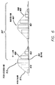
図6は、図4からの測定値を表すキャパシタンス測定値601と、図5の構成からの測定値を表す測定値603とを示す。測定値601は、図4に示す指401のようなタッチ物体の付近のセンサアレイ101のセンサのキャパシタンス測定値のセットの典型的な形状を表す。特に、指401の中心の付近の測定値は、中心から離れた測定値より大きい。それ故、測定値601の形状は、ある物体及びセンサアレイに対し、例えば、ガウス曲線のような曲線605でモデリングすることができる。曲線605は、例えば、指401の中心を表す局部最大値607を有する。又、曲線605は、局部最大値607の各側にテール端も有する。又、図6は、指401が遠方端303を越えてスペース307の外側に移動した後にセンサアレイ101の遠方端303付近のセンサによって測定されたキャパシタンス測定値のセットを表す測定値603も示している。このケースでは、測定値603は、指401がスペース307の内側にある場合に測定される曲線のテール端609しか表していない。換言すれば、測定値603は、少なくとも測定値601と比較して、不完全な測定値セットである。
6 shows a
例えば、タッチスクリーンのセンサアレイの真上にある物体の位置及び/又はホバー高さを決定するのに使用される典型的なアルゴリズムにおいて、測定値601のような完全な測定値セットは、局部最大値607の決定から位置を決定するに充分なデータを与えることができる。このケースでは、局部最大値607の決定は、容易に行うことができる。というのは、測定値601のセットが局部最大値607をまたいでいるからである。換言すれば、局部最大値607は、測定値601の範囲内にある。他方、測定値603は、完全な曲線のテール端609の部分しか表しておらず、ローカル最大値の直接的な情報を含んでいない。従って、テール端609の形状は分かるが、センサアレイ101が遠方端303を越えて延びる場合に測定される完全な曲線の形状は分からない。
For example, in a typical algorithm used to determine the position and / or hover height of an object directly above a touch screen sensor array, a complete set of measurements, such as
図6は、未知の測定値615のセットに基づく未知の曲線611の1つの考えられる推定を示す。未知の曲線611及び未知の測定値615は、実際には測定されないが、センサのアレイの遠方端付近及びアレイの真上のスペースの外側にある物体により生じるテール端測定値をどのように使用して物体のホバー位置及び/又はホバー高さを検出するかの一般的な考え方を示すために、例示の目的で設けられている。特に、測定値603は、未知の曲線611のテール端609を表しており、未知の曲線611のパラメータを決定して、その結果、未知の局部最大値613を決定することで、物体のホバー位置及び/又は高さに関する情報を与えられることが認識される。その結果、センサアレイ101のセンサ位置の範囲の外側にある物体のホバー位置を、その決定されたローカル最大値613に基づいて決定することができる。
FIG. 6 shows one possible estimate of the unknown curve 611 based on a set of
図7は、測定値603を使用してスペース307の外側にある物体のホバー位置を検出する例示的方法を示す。図7の例示的方法及びここに述べる他の方法は、例えば、タッチ及びホバーコントロールシステム107、即ち中央処理ユニット(CPU)(図示せず)及び/又は別のプロセッサのような汎用プロセッサにおいて遂行され、そしてその結果は、例えば、当業者であれば、本開示に鑑み容易に理解されるように、メモリ313及び/又は別のメモリ(図示せず)に記憶される。図7を参照すれば、測定値603が得られ(701)、そしてスペース307の外側の局部最大値を含むモデルに適合される(702)。測定値603を適合して指401のホバー位置を決定するために、種々のモデル及び種々の適合方法が使用される。例えば、測定値603に対して適合するための曲線の形式のモデルとしてガウス曲線が使用されてもよい。特に、図6から、ある位置における指401の測定値601の1つのセットを近似する曲線605は、実質的にガウス形状のように見えることが観察される。それ故、指401と同様の物体により得られるセンサの読みは、ガウス形状になると仮定するのが合理的である。このケースでは、測定値603を適合するのに選択されるモデルは、ガウス曲線である。
FIG. 7 shows an exemplary method for detecting hover position of an object outside the
種々の方法を使用して、ガウス曲線を測定値603に適合させることができる。例えば、使用することのできる1つの方法は、最大見込み推定方法である。このケースでは、例えば、最大高さ及び標準偏差のようなガウス曲線のパラメータが、推定ガウス曲線と測定値603との間の差(エラー)が最小になるまで、調整される。推定エラーが最も小さいガウス曲線を使用して、未知の局部最大値613を決定し、これは、スペース307の外側の指401の位置を表す。
Various methods can be used to fit the Gaussian curve to the measured
ある実施形態において、使用するモデルは、別の形式の曲線でよく、例えば、変形ガウス曲線、以前のデータから決定されるカスタム曲線、等でよい。ある実施形態において、使用するモデルは、曲線でなくてもよく、単にルックアップテーブル(LUT)に記憶されたパラメータのセットでもよい。このケースでは、個々のセンサ測定値が、ルックアップテーブルに記憶された値に個々に適合され、最良の一致が見つかると、ルックアップテーブルは、物体の決定されたホバー位置を表す単一の値を単に返送する。ルックアップテーブルにおけるホバー位置の値は、例えば、特定のセンサ測定値、以前に計算された曲線モデル、等に対応するホバー位置の経験的データに基づくものである。 In some embodiments, the model used may be another type of curve, such as a modified Gaussian curve, a custom curve determined from previous data, etc. In some embodiments, the model used may not be a curve, but may simply be a set of parameters stored in a lookup table (LUT). In this case, individual sensor measurements are individually matched to the values stored in the lookup table, and once the best match is found, the lookup table is a single value that represents the determined hover position of the object. Simply return. The value of the hover position in the look-up table is based on empirical data on the hover position corresponding to, for example, specific sensor measurements, previously calculated curve models, and the like.
ある実施形態において、ホバー位置及び/又は高さの決定に他のパラメータが使用されてもよい。例えば、物体のサイズ、導電率、等が知られている場合には、測定されたキャパシタンスをモデルに適合させるときにこれらのパラメータが含まれる。ある実施形態において、モデルは、局部最大値を含む物体のキャパシタンス測定値の以前のセットに基づくものである。 In certain embodiments, other parameters may be used to determine hover position and / or height. For example, if the object size, conductivity, etc. are known, these parameters are included when fitting the measured capacitance to the model. In some embodiments, the model is based on a previous set of object capacitance measurements including local maxima.
ある実施形態では、キャパシタンス測定値を適合させるのに使用するモデルを決定するのに、物体のサイズ、速度、等に関する情報が考慮される。例えば、図4−6は、指401がセンサアレイ101の中央から遠方端303に向かって移動し、次いで、遠方端303を越えて、スペース307の外側へ移動する例示的な状態を示す。この例示的なケースでは、この方法は、測定値601のセットを、測定値603を適合させるモデルとして記録することができる。測定値601は、例えば、ルックアップテーブルに直接記憶されてもよい。別の実施形態では、測定値601を補間して、測定値603の適合に使用するモデル曲線を作成してもよい。
In some embodiments, information regarding the size, speed, etc. of the object is taken into account in determining the model used to fit the capacitance measurement. For example, FIGS. 4-6 illustrate an exemplary situation where the
ある実施形態では、測定値603を適合するときに、指の速度のような指401に関する他の情報を使用できる。例えば、個別のアルゴリズムにより決定される指401の速度は、適合プロセス中に使用されるモデルのパラメータとして使用される。このようにして、指401がスペース307の外側へ移動するときに測定値601の曲線又は表現を追跡して、曲線の局部最大値が測定値603において直接検出されなくても、局部的最大値に関する情報を維持できるようにする。
In some embodiments, other information about the
ある実施形態において、測定値の適合中に複数のモデルを考慮することができる。例えば、この方法は、2つ以上の物体がセンサアレイの遠方端付近で特定のキャパシタンス測定値を生じさせると決定し、そしてこの方法は、2つ以上のモデル及び/又は適合方法を使用して、そのキャパシタンス測定値を1つ以上の物体及び/又は物体の形式に適合させるよう試みる。例えば、この方法は、キャパシタンス測定値が「3本の指」又は「2本の親指」等の同じ形式の複数の物体により生じたものであると決定する。又、この方法は、キャパシタンス測定値が「指及び親指」又は「こぶし及び親指」等の異なる形式の物体により生じたものであると決定する。この方法は、キャパシタンス測定値が「2本の指及びこぶし」又は「左親指、右指及び手のひら」等の種々の数及び形式の物体により生じたものであると決定する。この方法は、異なる数及び/又は形式の物体に対応する異なるモデルをキャパシタンス測定値の異なる部分に適合させる。例えば、この方法は、キャパシタンス測定値が、2つの物体、例えば、以前にセンサアレイから去るときに追跡された指、及び親指と推定される未知の物体によって生じたものであると決定する。このケースでは、この方法は、個々のセンサ測定値をLUT内の以前に記憶された値に適合させることにより指に対応するキャパシタンス測定値を以前に記憶されたデータに適合させると共に、親指に関連したパラメータの最大見込み推定値を使用して親指に対応するキャパシタンス測定値をガウス曲線に適合させる。従って、ある実施形態では、キャパシタンス測定値を適合するときに物体の数及び各物体のパラメータを推定する。 In certain embodiments, multiple models can be considered during measurement adaptation. For example, the method determines that two or more objects produce a particular capacitance measurement near the far end of the sensor array, and the method uses two or more models and / or fitting methods. Attempt to adapt the capacitance measurement to one or more objects and / or object types. For example, this method determines that the capacitance measurement is caused by multiple objects of the same type, such as “three fingers” or “two thumbs”. This method also determines that the capacitance measurement is caused by a different type of object such as “finger and thumb” or “fist and thumb”. This method determines that the capacitance measurement is caused by various numbers and types of objects such as “two fingers and fist” or “left thumb, right finger and palm”. This method fits different models corresponding to different numbers and / or types of objects to different parts of the capacitance measurement. For example, the method determines that the capacitance measurement is caused by two objects, for example, a finger previously tracked when leaving the sensor array and an unknown object presumed to be the thumb. In this case, the method adapts the capacitance measurement corresponding to the finger to the previously stored data by adapting the individual sensor measurements to the previously stored values in the LUT and related to the thumb. Fit the capacitance measurement corresponding to the thumb to a Gaussian curve using the maximum likelihood estimate of the selected parameter. Thus, in some embodiments, the number of objects and the parameters of each object are estimated when fitting capacitance measurements.
ある実施形態において、センサアレイの遠方端付近及びセンサアレイの真上のスペースの外側にある物体の位置及び/又は動きは、ユーザ入力として処理される。例えば、物体の位置及び/又は動きは、現在表示されているグラフィックユーザインターフェイス(GUI)への入力、GUIとは独立した入力、等として処理される。 In some embodiments, the position and / or movement of objects near the far end of the sensor array and outside the space directly above the sensor array is processed as user input. For example, the position and / or movement of an object is processed as input to a currently displayed graphic user interface (GUI), input independent of the GUI, and the like.
例えば、図7を参照して述べた方法は、センサアレイの遠方端付近及びセンサアレイの真上のスペースの外側にある物体を含む1つ以上の物体の位置及び/又は動きに基づいてユーザ入力を決定するように使用される。センサアレイの外側の境界エリアにある物体のホバー位置は、複数のホバー位置を決定するために何回も測定される。物体の動きは、複数の測定されたホバー位置に対応して決定され、そして物体のその決定された位置に基づいて入力が検出される。例えば、境界エリアで上方に動くと検出された指は、現在再生されている音楽の音量を増加するためのユーザ入力として解釈される。ある実施形態では、ユーザ入力は、GUIをコントロールする。例えば、境界エリアで動いていると検出された指は、指の動きに対応して、アイコン、スライダー、テキストボックス、カーソル、等のGUIアイテムをコントロールすることができる。 For example, the method described with reference to FIG. 7 is based on user input based on the position and / or movement of one or more objects, including objects near the far end of the sensor array and outside the space directly above the sensor array. Used to determine. The hover position of an object in the boundary area outside the sensor array is measured many times to determine a plurality of hover positions. The movement of the object is determined corresponding to a plurality of measured hover positions, and an input is detected based on the determined position of the object. For example, a finger detected as moving upward in the border area is interpreted as a user input to increase the volume of the currently played music. In some embodiments, user input controls the GUI. For example, a finger detected as moving in the boundary area can control GUI items such as an icon, a slider, a text box, and a cursor in accordance with the movement of the finger.
ある実施形態では、ユーザ入力は、センサアレイの真上の物体の位置及び/又は動きと、センサアレイの遠方端付近及びセンサアレイの真上のスペースの外側にある物体の位置及び/又は動きとを含む情報の組み合わせに基づくものである。図3−5を参照すれば、例えば、カバー面305にGUIが表示される。図7を参照して上述した方法は、例えば、指401がタッチスクリーンを去るときにGUIアイテムの動きをコントロールするように使用される。例えば、指401は、センサアレイ101の真上の入力を開始し、GUIにより表示されたアイコンを「ドラグ」する。アイコンは、スペース307の内側の指401の動きに対応する経路に沿って移動するようにディスプレイドライバ319によりコントロールされる。指401がスペース307の外側に移動しそしてセンサアレイ101の遠方端付近の位置で停止することが検出された場合には、ディスプレイドライバ319は、指がタッチスクリーンを去る直前まで指の経路に沿って移動を続けるようアイコンをコントロールすることができる。ディスプレイドライバ319は、指401がその停止位置から離れることが検出されたときにアイコンの動きを止めることができる。これは、例えば、指がタッチスクリーンを去るときでも、ドラグ及び/又はポインティングアクションを続けられる上で助けとなる。
In some embodiments, the user input includes the position and / or movement of an object directly above the sensor array and the position and / or movement of an object near the far end of the sensor array and outside the space directly above the sensor array. It is based on a combination of information including 3-5, for example, the GUI is displayed on the
図8−11は、タッチ感知及びホバー感知の共同動作を遂行できる異なるハードウェア、ソフトウェア、及びファームウェアの実施形態を例示する。例えば、ある実施形態において、センサの1つのセットをホバー感知に使用することができ、そしてセンサの別のセットをタッチ感知に使用することができる。例えば、自己キャパシタンス測定用に構成された電極をホバー感知に使用することができ、そして相互キャパシタンス測定用に構成された電極をタッチ感知に使用することができる。これらのケースでは、タッチ感知とホバー感知との間の切り換えを行って、電力を節約し、干渉を減少し、等々を行うことができる。他の実施形態では、同じセンサをホバー感知とタッチ感知との間で共用してもよい。これらのケースでは、例えば、共用される回路素子を使用するために切り換えが必要である。ソフトウェア及び/又はファームウェアは、タッチ及びホバー感知の共同動作をコントロールすることができる。例えば、特定の構成に基づいて、ソフトウェア及び/又はファームウェアは、例えば、シングルモード動作においてタッチ感知とホバー感知との間をいつ切り換えるか決定し、例えば、マルチモード動作においてタッチ及びホバー感知いつ同時に遂行するか決定し、センサの異なる部分をアクチベートしてタッチ及び/又はホバー感知を遂行し、等々を行うことができる。 FIGS. 8-11 illustrate different hardware, software, and firmware embodiments that can perform the joint operation of touch sensing and hover sensing. For example, in one embodiment, one set of sensors can be used for hover sensing and another set of sensors can be used for touch sensing. For example, an electrode configured for self-capacitance measurement can be used for hover sensing, and an electrode configured for mutual capacitance measurement can be used for touch sensing. In these cases, switching between touch sensing and hover sensing can be done to save power, reduce interference, and so on. In other embodiments, the same sensor may be shared between hover sensing and touch sensing. In these cases, for example, switching is required to use shared circuit elements. Software and / or firmware can control the joint operation of touch and hover sensing. For example, based on a particular configuration, the software and / or firmware may determine when to switch between touch sensing and hover sensing, for example, in single mode operation, for example, simultaneously when touch and hover sensing are performed in multi-mode operation. Different parts of the sensor can be activated to perform touch and / or hover sensing, and so on.
図8−9は、タッチ感知とホバー感知との間を切り換えるのに使用されるハードウェア切り換えの例示的実施形態を示す。 Figures 8-9 illustrate an exemplary embodiment of a hardware switch used to switch between touch sensing and hover sensing.
図8は、タッチ及びホバー回路803及びタッチ回路805を含むセンサアレイ801を備えた例示的なタッチ及びホバー感知システム800を示す。例えば、タッチ及びホバー回路803は、ホバー事象を感知するための自己キャパシタンスセンサとして動作できる複数の導電線のセットであり、そしてタッチ回路805は、タッチ及びホバー回路803の導電線と対にされたときタッチ事象を感知できる複数の導電線の別のセットである。それ故、センサアレイ801は、タッチ感知段階及びホバー感知段階の両方において動作する共通の回路を備えている。センサコントロールシステム807は、ホバー感知に対応する信号をタッチ及びホバー回路803のみに送信し、そしてタッチ感知に対応する信号をタッチ及びホバー回路803及びタッチ回路805に送信することにより、タッチ及びホバーの両方を検出するようにセンサアレイ801を動作できる。それ故、センサコントロールシステム807は、一体型タッチコントロールシステム・ホバーコントロールシステムとして働き、以下に詳細に述べるように、タッチ感知とホバー感知との間をいつ切り換えるべきか決定することができる。
FIG. 8 illustrates an exemplary touch and hover sensing system 800 with a sensor array 801 that includes a touch and hover circuit 803 and a
図9は、センサアレイ901及びセンサコントロールシステム903を含む例示的タッチ及びホバー感知システム900を示す。センサコントロールシステム903は、スイッチングシステム905と、タッチコントロールシステム907と、ホバーコントロールシステム909と、低漏洩アナログスイッチ911とを含む。動作中に、スイッチングシステム905は、タッチ感知からホバー感知への切り換え及びそれとは逆の切り換えをいつ行うべきか決定し、そして低漏洩アナログスイッチ911を動作して、タッチコントロールシステム907とホバーコントロールシステム909との間を適宜に切り換える。タッチ感知段階中には、タッチコントロールシステムがAC信号をセンサアレイ901へ送信して、AC信号から生じるセンサアレイのキャパシタンスを測定する。ホバー感知段階中には、ホバーコントロールシステム909がセンサアレイ901へAC信号を送信して、AC信号から生じるセンサアレイ901のキャパシタンスを測定する。
FIG. 9 illustrates an exemplary touch and hover
図10−11は、タッチ及びホバーを一緒に感知する例示的な方法を示し、これは、例えば、ソフトウェア、ファームウェア、特定用途向け集積回路(ASIC)、等で具現化することができる。 FIGS. 10-11 illustrate an exemplary method of sensing touch and hover together, which can be implemented, for example, in software, firmware, application specific integrated circuits (ASICs), and the like.
図10は、タッチスクリーン300のようなタッチ及びホバー感知装置上又はその付近でタッチ事象及びホバー事象を検出するための例示的な方法を示す。タッチ検出段階中には、タッチ及びホバーコントロールシステム107は、センサアレイ101へ第1のAC信号を送信し(1001)、そしてセンサアレイの第1キャパシタンスを測定する(1002)。タッチ及びホバーコントロールシステム107は、その第1キャパシタンスに基づいてタッチ事象を検出し(1003)、そしてタッチ事象のデータ、例えば、位置、サイズ、形状、ジェスチャーデータ、等をメモリに記憶する(1004)。ホバー検出段階中には、タッチ及びホバーコントロールシステム107は、センサアレイ101へ第2のAC信号を送信し(1005)、そしてセンサアレイの第2キャパシタンスを測定する(1006)。タッチ及びホバーコントロールシステム107は、第2キャパシタンスに基づいてホバー事象を検出し(1009)、そしてホバー事象データ、例えば、位置、高さ、サイズ、ジェスチャーデータ、等を記憶する(1010)。
FIG. 10 illustrates an exemplary method for detecting touch and hover events on or near a touch and hover sensing device such as
タッチ検出段階及びホバー検出段階中又はそれらの間に他の動作を行うことができる。例えば、ディスプレイドライバ319は、タッチ検出段階とホバー検出段階との間の表示段階にディスプレイ回路317へ画像信号を送信することができる。タッチ及び/又はホバー感知段階中に、ACシールド駆動システム203が上述したように動作して、伝送線ACシールド308を使用して伝送線309をシールドし、そしてACシールド201を使用してカバー面305から発生する電界を増加させる。タッチ検出段階及びホバー検出段階は、任意の順序で行うことができる。
Other actions can be performed during or between the touch detection phase and the hover detection phase. For example, the
ある実施形態では、タッチ及びホバーを同時に感知することができず、即ち単一の感知モード(非重畳タッチ/ホバー感知)しか行えない。このケースでは、ある実施形態において、タッチ感知及びホバー感知が時間マルチプレクスされ、即ちタッチ及びホバー感知は、異なる非重畳時間周期中に行うことができる。感知動作をどのように時間マルチプレクスすべきか、即ち特定の時間にタッチ感知を行うべきか又はホバー感知を行うべきか(或いはどちらも行わないか)判断するための種々の方法を実施することができる。 In some embodiments, touch and hover cannot be sensed simultaneously, ie only a single sense mode (non-overlapping touch / hover sense). In this case, in some embodiments, touch sensing and hover sensing are time multiplexed, i.e., touch and hover sensing can occur during different non-overlapping time periods. Implementing various methods to determine how the sensing action should be time multiplexed, ie whether touch sensing or hover sensing should be done at a particular time (or neither) it can.
ある実施形態では、タッチ及びホバー感知は、同時に動作することができ、即ちマルチモード感知を行うことができる。システムがマルチモードのタッチ及びホバー感知を実行できる場合でも、あるケースでは単一モード感知を遂行するのが効果的である。例えば、特定の時間にタッチ感知又はホバー感知のいずれかが必要でない場合には、電力を節約するために単一モード感知への切り換えが望ましい。 In some embodiments, touch and hover sensing can operate simultaneously, i.e., can perform multi-mode sensing. Even if the system can perform multi-mode touch and hover sensing, in some cases it is effective to perform single-mode sensing. For example, if either touch sensing or hover sensing is not required at a particular time, switching to single mode sensing is desirable to save power.
ある実施形態では、タッチ感知及びホバー感知の動作を固定のスケジュールにより決定することができる。他の実施形態では、タッチ及びホバー感知の時間及び期間を動的に変化させることができ、これは、例えば、タッチ感知モード及びホバー感知モード、並びにおそらく表示モードのような他のモードを含む多数の動作モードの1つで動作するようにシステムを設定することにより行われる。例えば、図11は、タッチ及び/又はホバーを感知すべきかどうか決定するための例示的な方法を示す。タッチ感知動作を遂行し(1101)、タッチが検出されたかどうか決定することができる(1102)。タッチが検出された場合には、システムは、タッチ感知とホバー感知との間を切り換えるか、又はシステムがマルチモード感知を行える場合にはタッチ及びホバー感知を同時に遂行することにより、タッチ及びホバーの両感知を遂行することができる(1103)。タッチ及びホバーの両感知は、タッチが検出された後に行うことができる。というのは、タッチは、ユーザがホバー事象及びタッチ事象を遂行するユーザ活動期間を指示するからである。 In some embodiments, touch sensing and hover sensing behavior can be determined by a fixed schedule. In other embodiments, the time and duration of touch and hover sensing can be changed dynamically, including a number of other modes including, for example, touch sensing mode and hover sensing mode, and possibly display mode. This is done by setting the system to operate in one of the following operating modes. For example, FIG. 11 illustrates an exemplary method for determining whether to sense touch and / or hover. A touch sensing operation may be performed (1101) and a determination may be made as to whether a touch has been detected (1102). If a touch is detected, the system switches between touch sensing and hover sensing or, if the system is capable of multi-mode sensing, performs touch and hover sensing simultaneously to perform touch and hover sensing. Both sensings can be performed (1103). Both touch and hover sensing can be performed after a touch is detected. This is because a touch indicates a user activity period during which the user performs a hover event and a touch event.
1102においてタッチが検出されない場合には、システムは、ホバー検出を遂行し(1104)、そしてホバーが検出されたかどうか決定する(1105)。ホバーが検出された場合には、システムは、タッチ及びホバーの両感知を遂行することができる(1103)。というのは、ホバーがユーザ活動期間を指示するからである。1105においてホバーが検出されない場合には、システムは、再びホバー検出を遂行することができる(1104)。ホバーが検出されない限り、システムは、タッチ検出を遂行する必要はない。というのは、接近しつつある物体は、それが感知システムにタッチダウンする前に、ホバー検出を生じさせるからである。 If a touch is not detected at 1102, the system performs hover detection (1104) and determines whether a hover is detected (1105). If hover is detected, the system can perform both touch and hover sensing (1103). This is because the hover indicates the user activity period. If no hover is detected at 1105, the system can perform hover detection again (1104). As long as no hover is detected, the system need not perform touch detection. This is because an approaching object causes hover detection before it touches down the sensing system.
他のファクタを使用して、タッチを検出すべきか、ホバーを検出すべきか、その両方を検出すべきか、又はその両方とも検出すべきでないか決定することができる。例えば、ある実施形態では、接近しつつある物体をホバー感知中に検出し、そして物体がタッチ面に接触するのを待機してタッチ感知を遂行する。換言すれば、距離スレッシュホールドを使用してタッチ感知をアクチベートすることができる。ある実施形態では、例えば、タッチデータは必要とするがホバーデータは必要でない特定のソフトウェアアプリケーションによりタッチ/ホバーモードを決定することができる。ある実施形態では、タッチの現在数及び/又は位置をファクタとして使用することができる。例えば、小さな移動タッチスクリーン装置は、タッチ面にタッチする所定数、例えば、5回の接触まで、タッチ感知とホバー感知とを交互に行う。5回のタッチ接触が検出されると、装置は、ホバーの検出を停止し、タッチだけを検出する。というのは、ユーザが例えば第6の物体を使用してホバーを行う見込みが少ないからである。 Other factors can be used to determine whether touch should be detected, hover should be detected, both should be detected, or neither should be detected. For example, in some embodiments, an approaching object is detected during hover sensing, and touch sensing is performed waiting for the object to touch the touch surface. In other words, touch sensing can be activated using a distance threshold. In some embodiments, for example, touch / hover mode may be determined by a particular software application that requires touch data but does not require hover data. In some embodiments, the current number and / or location of touches can be used as a factor. For example, a small mobile touch screen device alternately performs touch sensing and hover sensing until a predetermined number of touches on the touch surface, for example, five touches. When five touch contacts are detected, the device stops hover detection and detects only touch. This is because the user is less likely to hover using, for example, the sixth object.
ある実施形態では、マルチモード動作を行うことができ、即ちタッチ感知及びホバー感知を同時に遂行できる。例えば、ある実施形態では、周波数マルチプレクシングを使用して、タッチ感知に使用されるAC信号を、ホバー感知に使用される異なる周波数のAC信号と合成することができる。ある実施形態では、AC信号のコード分割マルチプレクシングを使用して、同時のタッチ感知及びホバー感知を遂行することができる。 In some embodiments, multi-mode operation can be performed, i.e., touch sensing and hover sensing can be performed simultaneously. For example, in one embodiment, frequency multiplexing can be used to combine an AC signal used for touch sensing with an AC signal of a different frequency used for hover sensing. In some embodiments, code division multiplexing of AC signals can be used to perform simultaneous touch sensing and hover sensing.
周波数マルチプレクシング及びコード分割マルチプレクシングは、感知電極のような回路素子を使用してタッチ及びホバーを同時に検出できるようにする。例えば、センサの全アレイを同時に刺激して、タッチ及びホバーを検出してもよい。 Frequency multiplexing and code division multiplexing allow touch and hover to be detected simultaneously using circuit elements such as sensing electrodes. For example, the entire array of sensors may be stimulated simultaneously to detect touch and hover.
ある実施形態では、タッチ感知及びホバー感知は、例えば、タッチ感知についてセンサアレイの一部分を動作し、そしてホバー感知についてセンサアレイの別の部分を同時に動作することにより、スペースマルチプレクスされる。例えば、タッチ感知に使用するAC信号は、センサアレイの第1のセンサグループへ送信され、そしてホバー感知に使用するAC信号は、センサアレイの第2のセンサグループへ送信される。センサグループは、タッチ及びホバー感知が異なる時間にセンサアレイの異なる部分によって遂行されるように動的に切り換えられる。例えば、タッチ感知は、タッチが検出されるセンサアレイの部分についてアクチベートされ、そして残りのセンサは、ホバーを検出するように動作される。システムは、移動するタッチ物体を追跡し、そして移動する物体をたどるようにタッチを感知するセンサのグループを調整することができる。 In some embodiments, touch sensing and hover sensing are space multiplexed, eg, by operating one portion of the sensor array for touch sensing and simultaneously operating another portion of the sensor array for hover sensing. For example, an AC signal used for touch sensing is transmitted to a first sensor group of the sensor array, and an AC signal used for hover sensing is transmitted to a second sensor group of the sensor array. Sensor groups are dynamically switched so that touch and hover sensing are performed by different parts of the sensor array at different times. For example, touch sensing is activated for the portion of the sensor array where a touch is detected, and the remaining sensors are operated to detect hover. The system can track a moving touch object and adjust a group of sensors that sense the touch to follow the moving object.
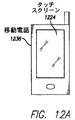
図12Aは、タッチセンサパネル1224及びディスプレイ装置1230を備えた例示的な移動電話1236を示し、そのタッチセンサパネルが、ここに述べる種々の実施形態の1つによる改良された容量性タッチ及びホバー感知を含む。
FIG. 12A shows an exemplary
図12Bは、タッチセンサパネル1224及びディスプレイ装置1230を備えた例示的なデジタルメディアプレーヤ1240を示し、そのタッチセンサパネルが、ここに述べる種々の実施形態の1つによる改良された容量性タッチ及びホバー感知を含む。 FIG. 12B shows an exemplary digital media player 1240 with a touch sensor panel 1224 and a display device 1230, which touch sensor panel is an improved capacitive touch and hover according to one of the various embodiments described herein. Includes sensing.
図12Cは、タッチセンサパネル(トラックパッド)1224及びディスプレイ1230を含む例示的なパーソナルコンピュータ1244を示し、該パーソナルコンピュータのタッチセンサパネル及び/又はディスプレイ(ディスプレイがタッチスクリーンの一部分である実施形態において)が、ここに述べる種々の実施形態よる改良された容量性タッチ及びホバー感知を含む。 FIG. 12C shows an exemplary personal computer 1244 that includes a touch sensor panel (trackpad) 1224 and a display 1230, wherein the touch sensor panel and / or display of the personal computer (in embodiments where the display is part of a touch screen). Includes improved capacitive touch and hover sensing according to various embodiments described herein.
以上、種々の実施形態を説明したが、それらは、例示に過ぎず、それに限定されるものでないことを理解されたい。同様に、種々の図面は、本開示のための例示的なアーキテクチャー又は他の構成を描くもので、本開示に含まれる特徴及び機能を理解する上で助けとなるものである。本開示は、ここに例示されたアーキテクチャー又は構成に限定されず、種々の別のアーキテクチャー及び構成を使用して具現化することもできる。更に、本開示は、種々の例示的実施形態及び具現化に関して上述したが、1つ以上の個々の実施形態で述べた種々の特徴及び機能は、それらについて述べた特定の実施形態への適用に限定されないことを理解されたい。むしろ、それらは、本開示の1つ以上の他の実施形態に、そのような実施形態が説明されたものであるかどうかに関わらず、又、そのような特徴がその説明された実施形態の一部分であると表現されたかどうかに関わらず、単独で、又はある組み合わせで、適用することができる。従って、本開示の範囲は、上述した例示的な実施形態により限定されるものではない。 While various embodiments have been described above, it should be understood that they are merely exemplary and not limiting. Similarly, the various drawings depict an exemplary architecture or other configuration for the present disclosure to assist in understanding the features and functions included in the present disclosure. The present disclosure is not limited to the architecture or configuration illustrated herein, and may be implemented using various other architectures and configurations. Further, although the present disclosure has been described above with reference to various exemplary embodiments and implementations, the various features and functions described in one or more individual embodiments may be adapted for application to the specific embodiments described. It should be understood that it is not limited. Rather, they do not matter whether such embodiment is described in one or more other embodiments of the present disclosure, and such features are also described in the described embodiment. It can be applied alone or in some combination, whether or not expressed as part. Accordingly, the scope of the present disclosure is not limited by the exemplary embodiments described above.
よって、上記を勘案して、いくつかの開示された実施の形態は、カバー面と、前記カバー面に実質的に隣接したセンサアレイと、前記センサアレイへ第1の交流(AC)信号を送信しそしてその第1のAC信号から生じる前記センサアレイのキャパシタンスを測定するタッチ及びホバーコントロールシステムと、ACシールドであって、実質的にこのACシールドと前記カバー面との間に前記センサアレイが配置されるようなACシールドと、前記ACシールドへ第2のAC信号を送信して、第1の電圧が前記ACシールドの第2の電圧と実質的に同じになるようにするACシールド駆動システムと、を備えた容量性のタッチ及びホバー感知装置に関する。他の実施の形態において、前記容量性のタッチ及びホバー感知装置の前記センサアレイは、実質的に透明な導体を含む電極を備えている。他の実施の形態において、前記ACシールドは、前記センサアレイから電気的に分離される。他の実施の形態において、前記ACシールドは、不透明導体を含む電極を備えている。他の実施の形態において、前記容量性のタッチ及びホバー感知装置は、前記タッチ及びホバーコントロールシステムと前記センサアレイを接続する伝送線の少なくとも一部分を実質的に取り巻く第2のACシールドを更に備え、前記第1のAC信号は、その伝送線上に送信される。他の実施の形態において、前記第1のAC信号は、ある波形を有し、そして第2のAC信号は、その波形のバッファされたコピーから発生される。他の実施の形態において、前記容量性のタッチ及びホバー感知装置を備えたタッチスクリーンは、更に、前記タッチ及びホバーコントロールシステム及び前記ACシールドと実質的に並置されるディスプレイを備え、このディスプレイは、ディスプレイ回路を含み、そして実質的にこのディスプレイ回路と前記センサアレイとの間に前記ACシールドが配置される。Thus, in view of the above, some disclosed embodiments transmit a first alternating current (AC) signal to a cover surface, a sensor array substantially adjacent to the cover surface, and the sensor array. And a touch and hover control system for measuring the capacitance of the sensor array resulting from the first AC signal, and an AC shield, wherein the sensor array is disposed substantially between the AC shield and the cover surface. And an AC shield drive system that transmits a second AC signal to the AC shield such that a first voltage is substantially the same as a second voltage of the AC shield. , A capacitive touch and hover sensing device. In another embodiment, the sensor array of the capacitive touch and hover sensing device comprises an electrode comprising a substantially transparent conductor. In another embodiment, the AC shield is electrically isolated from the sensor array. In another embodiment, the AC shield includes an electrode including an opaque conductor. In another embodiment, the capacitive touch and hover sensing device further comprises a second AC shield substantially surrounding at least a portion of a transmission line connecting the touch and hover control system and the sensor array, The first AC signal is transmitted on the transmission line. In another embodiment, the first AC signal has a waveform and the second AC signal is generated from a buffered copy of the waveform. In another embodiment, the touch screen with the capacitive touch and hover sensing device further comprises a display substantially juxtaposed with the touch and hover control system and the AC shield, the display comprising: A display circuit is included and the AC shield is disposed substantially between the display circuit and the sensor array.
開示された他の実施の形態は、センサアレイの遠方端付近及びセンサアレイの真上のスペースの外側にある物体のホバー位置を検出する方法において、前記センサアレイの遠方端付近で、ある範囲のセンサ位置において前記センサアレイの複数のセンサのキャパシタンス測定値のセットを得る段階であって、そのキャパシタンス測定値は、物体により生じたものである段階と、前記キャパシタンス測定値のセットを、前記センサ位置の範囲の外側の位置で局部最大値を含む曲線を定義するモデルに適合させる段階と、前記局部最大値の位置に基づいてホバー位置を決定する段階と、を備えた方法に関する。他の実施の形態において、前記モデルは、前記物体のキャパシタンス測定値の以前のセットに基づくものであり、その以前のセットは、局部最大値を含む。他の実施の形態において、前記適合は、前記モデルのパラメータの最大見込み推定値を決定することを含む。他の実施の形態において、前記パラメータは、物体の導電率及び物体のサイズの少なくとも1つを含む。他の実施の形態において、前記適合は、前記物体の数及び各物体のパラメータを推定することを含む。他の実施の形態において、前記適合は、前記複数のセンサの中の第1センサのキャパシタンス測定値と前記センサアレイの複数の記憶されたキャパシタンス測定値の1つとの間の最も厳密な一致を決定することを含む。他の実施の形態において、前記方法は、センサアレイの遠方端付近及びセンサアレイの真上のスペースの外側にある物体の複数のホバー位置を検出する段階と、複数の検出されたホバー位置に対応する物体の動きを決定する段階と、前記決定された物体の動きに基づいてユーザ入力を検出する段階と、を備えている。他の実施の形態において、前記方法は、前記検出されたユーザ入力に基づいてグラフィックユーザインターフェイス(GUI)をコントロールする段階を更に備えている。他の実施の形態において、グラフィックユーザインターフェイスをコントロールする前記方法は、センサアレイの真上のスペースの内側での物体の動きに対応させてGUIのアイテムを動かす段階と、センサアレイの遠方端付近及びセンサアレイの真上のスペースの外側のホバー位置で物体の動きが停止することが検出されたときにGUIのアイテムの動きを続ける段階と、をさらに備えている。Another disclosed embodiment is a method for detecting the hover position of an object near the far end of a sensor array and outside the space just above the sensor array, in a range near the far end of the sensor array. Obtaining a set of capacitance measurements of a plurality of sensors of the sensor array at a sensor location, the capacitance measurement being caused by an object; and the set of capacitance measurements at the sensor location. And fitting to a model defining a curve including a local maximum at a position outside the range, and determining a hover position based on the position of the local maximum. In another embodiment, the model is based on a previous set of capacitance measurements of the object, the previous set including a local maximum. In another embodiment, the fitting includes determining a maximum likelihood estimate of the model parameter. In another embodiment, the parameter includes at least one of an object conductivity and an object size. In another embodiment, the adaptation includes estimating the number of objects and parameters of each object. In another embodiment, the adaptation determines the most exact match between a capacitance measurement of a first sensor in the plurality of sensors and one of a plurality of stored capacitance measurements of the sensor array. Including doing. In another embodiment, the method detects a plurality of hover positions of an object near the far end of the sensor array and outside the space directly above the sensor array, and corresponds to the plurality of detected hover positions. Determining a motion of the object to be detected, and detecting a user input based on the determined motion of the object. In another embodiment, the method further comprises controlling a graphic user interface (GUI) based on the detected user input. In another embodiment, the method of controlling a graphical user interface includes moving a GUI item in response to movement of an object inside a space directly above the sensor array, near the far end of the sensor array, and Continuing the movement of the GUI item when it is detected that the movement of the object stops at a hover position outside the space just above the sensor array.
開示された他の実施の形態は、センサアレイと、タッチ感知段階中に前記センサアレイへ第1の交流(AC)信号を送信し、そしてその第1のAC信号から生じる前記センサアレイの第1のキャパシタンスを測定するタッチコントロールシステム、及びホバー感知段階中に前記センサアレイへ第2の交流(AC)信号を送信し、そしてその第2のAC信号から生じる前記センサアレイの第2のキャパシタンスを測定するホバーコントロールシステムを含むセンサコントロールシステムと、前記センサコントロールシステムを前記タッチコントロールシステムとホバーコントロールシステムとの間で切り換えるスイッチングシステムと、を備えた容量性のタッチ及びホバー感知装置に関する。他の実施の形態において、前記第1のキャパシタンスは、相互キャパシタンスである。他の実施の形態において、前記第2のキャパシタンスは、自己キャパシタンスである。他の実施の形態において、前記センサアレイは、タッチ感知段階及びホバー感知段階の両方において動作する共通の回路を含む。他の実施の形態において、前記タッチコントロールシステムは、タッチコントロールシステム回路を含み、前記ホバーコントロールシステムは、ホバーコントロールシステム回路を含み、前記スイッチングシステムは、各々、タッチ感知段階及びホバーコントロール段階中に、前記タッチコントロールシステム回路を前記センサアレイに、又は前記ホバーコントロールシステム回路を前記センサアレイに、交互に接続する物理的スイッチを備えている。Another disclosed embodiment transmits a first alternating current (AC) signal to the sensor array during the touch sensing stage and the first of the sensor array resulting from the first AC signal. A touch control system for measuring the capacitance of the sensor array, and transmitting a second alternating current (AC) signal to the sensor array during the hover sensing phase and measuring a second capacitance of the sensor array resulting from the second AC signal The present invention relates to a capacitive touch and hover sensing device including a sensor control system including a hover control system and a switching system that switches the sensor control system between the touch control system and the hover control system. In another embodiment, the first capacitance is a mutual capacitance. In another embodiment, the second capacitance is a self-capacitance. In another embodiment, the sensor array includes a common circuit that operates in both the touch sensing stage and the hover sensing stage. In another embodiment, the touch control system includes a touch control system circuit, the hover control system includes a hover control system circuit, and the switching system includes a touch sensing stage and a hover control stage, respectively. There is a physical switch that alternately connects the touch control system circuit to the sensor array or the hover control system circuit to the sensor array.
開示された他の実施の形態は、タッチ及びホバー感知装置上又はその付近でタッチ事象及びホバー事象を検出する方法に関し、その方法は、前記装置のセンサアレイへ第1の交流(AC)信号を送信しそしてその第1のAC信号から生じる前記センサアレイの第1のキャパシタンスを測定する段階と、前記第1のキャパシタンスに基づいてタッチ事象を検出する段階と、前記センサアレイへ第2の交流(AC)信号を送信しそしてその第2のAC信号から生じる前記センサアレイの第2のキャパシタンスを測定する段階と、前記第2のキャパシタンスに基づいてホバー事象を検出する段階と、を備えている。他の実施の形態において、前記第1のAC信号及び第2のAC信号は、周波数マルチプレクシング及びコード分割マルチプレクシングの一方により同時に送信される。他の実施の形態において、前記第1のAC信号及び第2のAC信号は、スペースマルチプレクシングにより送信され、この場合に、第1のAC信号は、前記センサアレイの第1のセンサグループへ送信され、そして第2のAC信号は、前記センサアレイの第2のセンサグループへ送信される。他の実施の形態において、前記第1のAC信号は、タッチ感知段階中に送信され、そして前記第2のAC信号は、タッチ感知段階とは重畳しないホバー感知段階中に送信され、前記方法は、更に、前記タッチ感知段階及びホバー感知段階を含む複数の動作段階の1つにおいて前記装置を動作するようにセットする段階を含む。他の実施の形態において、前記動作段階は、所定のスケジュール、外部コンピュータプロセスからの要求、検出される物体の現在数及び位置、及びセンサアレイからの物体の距離、の少なくとも1つに基づいてセットされる。Another disclosed embodiment relates to a method for detecting touch and hover events on or near a touch and hover sensing device, the method including a first alternating current (AC) signal to a sensor array of the device. Transmitting and measuring a first capacitance of the sensor array resulting from the first AC signal; detecting a touch event based on the first capacitance; and a second alternating current to the sensor array ( Transmitting an AC) signal and measuring a second capacitance of the sensor array resulting from the second AC signal, and detecting a hover event based on the second capacitance. In another embodiment, the first AC signal and the second AC signal are transmitted simultaneously by one of frequency multiplexing and code division multiplexing. In another embodiment, the first AC signal and the second AC signal are transmitted by space multiplexing, in which case the first AC signal is transmitted to the first sensor group of the sensor array. And a second AC signal is transmitted to a second sensor group of the sensor array. In another embodiment, the first AC signal is transmitted during a touch sensing phase, and the second AC signal is transmitted during a hover sensing phase that does not overlap the touch sensing phase, the method comprising: And further comprising setting the device to operate in one of a plurality of operational phases including the touch sensing phase and the hover sensing phase. In another embodiment, the operational phase is set based on at least one of a predetermined schedule, a request from an external computer process, a current number and location of detected objects, and a distance of the object from the sensor array. Is done.
100:タッチ及びホバー感知装置
101:センサアレイ
103:水平線
105:垂直線
107:タッチ及びホバーコントロールシステム
201:AC接地シールド
203:ACシールド駆動システム
250、253、255:電界
300:タッチスクリーン
301:境界
303:遠方端
305:カバー面
307:スペース
308:伝送線ACシールド
309:伝送線
311:波形
313:メモリ
315:バッファされたコピー
317:ディスプレイ回路
319:ディスプレイドライバ
401:指
403、501:電界線
DESCRIPTION OF SYMBOLS 100: Touch and hover sensing apparatus 101: Sensor array 103: Horizontal line 105: Vertical line 107: Touch and hover control system 201: AC ground shield 203: AC shield drive system 250, 253, 255: Electric field 300: Touch screen 301: Boundary 303: Distant end 305: Cover surface 307: Space 308: Transmission line AC shield 309: Transmission line 311: Waveform 313: Memory 315: Buffered copy 317: Display circuit 319: Display driver 401:
Claims (20)
前記カバー面に実質的に隣接したセンサアレイと、
前記センサアレイへ第1の交流(AC)信号を送信しそしてその第1のAC信号から生じる前記センサアレイのキャパシタンスを測定するタッチコントロールシステム及びホバーコントロールシステムを含むセンサコントロールシステムと、
ACシールドであって、実質的にこのACシールドと前記カバー面との間に前記センサアレイが配置されるようなACシールドと、
タッチ検出構成からホバー検出構成へ前記センサアレイを切り換える機能を有するスイッチング回路であって、前記センサアレイが、前記タッチ検出構成において相互キャパシタンスモードで動作し、前記ホバー検出構成において自己キャパシタンスモードで動作するように構成されている、スイッチング回路と、
を備えた容量性のタッチ及びホバー感知装置。 A cover surface;
A sensor array substantially adjacent to the cover surface;
A sensor control system including a touch control system and a hover control system for transmitting a first alternating current (AC) signal to the sensor array and measuring a capacitance of the sensor array resulting from the first AC signal;
An AC shield, wherein the sensor array is substantially disposed between the AC shield and the cover surface;
A switching circuit having a function of switching the sensor array from a touch detection configuration to a hover detection configuration, wherein the sensor array operates in a mutual capacitance mode in the touch detection configuration and operates in a self-capacitance mode in the hover detection configuration A switching circuit configured as
Capacitive touch and hover sensing device with
前記タッチスクリーンは、更に、前記タッチ及びホバーコントロールシステム及び前記ACシールドと実質的に並置されるディスプレイを備え、このディスプレイは、ディスプレイ回路を含み、そして実質的にこのディスプレイ回路と前記センサアレイとの間に前記ACシールドが配置される、タッチスクリーン。 A touch screen comprising the capacitive touch and hover sensing device according to claim 1,
The touch screen further comprises a display substantially juxtaposed with the touch and hover control system and the AC shield, the display including a display circuit and substantially between the display circuit and the sensor array. A touch screen between which the AC shield is disposed.
前記センサアレイの遠方端付近で、ある範囲のセンサ位置において前記センサアレイの複数のセンサの自己キャパシタンス測定値のセットを得る段階であって、そのキャパシタンス測定値は、前記第1の物体により生じたものである段階と、
前記自己キャパシタンス測定値のセットを、前記センサ位置の範囲の外側の位置で局部最大値を含む曲線を定義するモデルに適合させる段階と、
前記局部最大値の位置に基づいてホバー位置を決定する段階と、
第2の物体のタッチ位置を検出するために、前記センサアレイの前記複数のセンサの相互キャパシタンス測定値のセットを得る段階と、
を備えた方法。 In a method for detecting a hover position of a first object that is near the far end of a sensor array and outside the space just above the sensor array,
Obtaining a set of self- capacitance measurements of a plurality of sensors of the sensor array at a range of sensor positions near the far end of the sensor array, wherein the capacitance measurements are caused by the first object; The stage that is,
Fitting the set of self- capacitance measurements to a model defining a curve containing a local maximum at a position outside the range of sensor positions;
Determining a hover position based on the position of the local maximum value;
Obtaining a set of mutual capacitance measurements of the plurality of sensors of the sensor array to detect a touch position of a second object;
With a method.
センサアレイの遠方端付近及びセンサアレイの真上のスペースの外側にある前記第1の物体の複数のホバー位置を検出する段階と、
複数の検出されたホバー位置に対応する前記第1の物体の動きを決定する段階と、
前記決定された前記第1の物体の動きに基づいてユーザ入力を検出する段階と、
を備えた方法。 A method for detecting user input including a method for detecting a hover position according to claim 9 ,
Detecting a plurality of hover positions of the first object near the far end of the sensor array and outside the space directly above the sensor array;
Determining a movement of the first object corresponding to a plurality of detected hover positions;
Detecting a user input based on the determined movement of the first object;
With a method.
センサアレイの真上のスペースの内側での前記第1の物体の動きに対応させてGUIのアイテムを動かす段階と、
センサアレイの遠方端付近及びセンサアレイの真上のスペースの外側のホバー位置で前記第1の物体の動きが停止することが検出されたときにGUIのアイテムの動きを続ける段階と、
を備えた方法。 A method for controlling movement of an item in a graphic user interface (GUI), including the method for detecting hover position according to claim 9 .
Moving a GUI item in response to the movement of the first object inside the space directly above the sensor array;
Continuing the movement of the GUI item when it is detected that the movement of the first object stops near the far end of the sensor array and at a hover position outside the space just above the sensor array;
With a method.
前記タッチコントロールシステムは、タッチコントロールシステム回路を含み、前記ホバーコントロールシステムは、ホバーコントロールシステム回路を含み、前記スイッチングシステムは、各々、タッチ感知段階及びホバーコントロール段階中に、前記タッチコントロールシステム回路を前記センサアレイに、又は前記ホバーコントロールシステム回路を前記センサアレイに、交互に接続する物理的スイッチを備えた、請求項1に記載の容量性のタッチ及びホバー感知装置。 A switching system for switching the sensor control system between a touch control system and a hover control system ;
The touch control system includes a touch control system circuit, the hover control system includes a hover control system circuit, and the switching system includes the touch control system circuit during the touch sensing stage and the hover control stage, respectively. The capacitive touch and hover sensing device of claim 1, comprising a physical switch that alternately connects the sensor array or the hover control system circuit to the sensor array .
前記装置のセンサアレイへ第1の交流(AC)信号を送信しそしてその第1のAC信号から生じる前記センサアレイの相互キャパシタンスを測定する段階と、
前記相互キャパシタンスに基づいてタッチ事象を検出する段階と、
前記センサアレイへ第2の交流(AC)信号を送信しそしてその第2のAC信号から生じる前記センサアレイの自己キャパシタンスを測定する段階と、
前記自己キャパシタンスに基づいてホバー事象を検出する段階と、
を備えた方法。 In a method for detecting touch and hover events on or near a touch and hover sensing device,
Transmitting a first alternating current (AC) signal to the sensor array of the device and measuring the mutual capacitance of the sensor array resulting from the first AC signal;
Detecting a touch event based on the mutual capacitance;
Transmitting a second alternating current (AC) signal to the sensor array and measuring the self- capacitance of the sensor array resulting from the second AC signal;
Detecting a hover event based on the self- capacitance;
With a method.
前記タッチ感知段階及びホバー感知段階を含む複数の動作段階の1つにおいて前記装置を動作するようにセットする段階を含む、請求項16に記載の方法。 The first AC signal is transmitted during a touch sensing phase, and the second AC signal is transmitted during a hover sensing phase that does not overlap the touch sensing phase, the method further comprising:
The method of claim 16, comprising setting the device to operate in one of a plurality of operational stages including the touch sensing stage and the hover sensing stage.
Applications Claiming Priority (3)
| Application Number | Priority Date | Filing Date | Title |
|---|---|---|---|
| US12/501,382 | 2009-07-10 | ||
| US12/501,382 US9323398B2 (en) | 2009-07-10 | 2009-07-10 | Touch and hover sensing |
| PCT/US2010/041391 WO2011005977A2 (en) | 2009-07-10 | 2010-07-08 | Touch and hover sensing |
Related Child Applications (1)
| Application Number | Title | Priority Date | Filing Date |
|---|---|---|---|
| JP2014157386A Division JP5995922B2 (en) | 2009-07-10 | 2014-08-01 | Touch and hover detection |
Publications (2)
| Publication Number | Publication Date |
|---|---|
| JP2012533122A JP2012533122A (en) | 2012-12-20 |
| JP5592948B2 true JP5592948B2 (en) | 2014-09-17 |
Family
ID=43427088
Family Applications (2)
| Application Number | Title | Priority Date | Filing Date |
|---|---|---|---|
| JP2012519733A Expired - Fee Related JP5592948B2 (en) | 2009-07-10 | 2010-07-08 | Touch and hover detection |
| JP2014157386A Expired - Fee Related JP5995922B2 (en) | 2009-07-10 | 2014-08-01 | Touch and hover detection |
Family Applications After (1)
| Application Number | Title | Priority Date | Filing Date |
|---|---|---|---|
| JP2014157386A Expired - Fee Related JP5995922B2 (en) | 2009-07-10 | 2014-08-01 | Touch and hover detection |
Country Status (7)
| Country | Link |
|---|---|
| US (3) | US9323398B2 (en) |
| EP (2) | EP2452256A2 (en) |
| JP (2) | JP5592948B2 (en) |
| KR (2) | KR101617563B1 (en) |
| CN (2) | CN102483673B (en) |
| AU (1) | AU2010271353B2 (en) |
| WO (1) | WO2011005977A2 (en) |
Cited By (1)
| Publication number | Priority date | Publication date | Assignee | Title |
|---|---|---|---|---|
| WO2018159460A1 (en) | 2017-03-03 | 2018-09-07 | アルプス電気株式会社 | Input device and method for controlling same |
Families Citing this family (269)
| Publication number | Priority date | Publication date | Assignee | Title |
|---|---|---|---|---|
| US7920129B2 (en) | 2007-01-03 | 2011-04-05 | Apple Inc. | Double-sided touch-sensitive panel with shield and drive combined layer |
| US20090174676A1 (en) | 2008-01-04 | 2009-07-09 | Apple Inc. | Motion component dominance factors for motion locking of touch sensor data |
| US8358142B2 (en) | 2008-02-27 | 2013-01-22 | Cypress Semiconductor Corporation | Methods and circuits for measuring mutual and self capacitance |
| US8363031B2 (en) * | 2008-09-24 | 2013-01-29 | 3M Innovative Properties Company | Mutual capacitance measuring circuits and methods |
| US8487639B1 (en) | 2008-11-21 | 2013-07-16 | Cypress Semiconductor Corporation | Receive demodulator for capacitive sensing |
| US8902191B2 (en) * | 2009-01-28 | 2014-12-02 | Synaptics Incorporated | Proximity sensing for capacitive touch sensors |
| US9740341B1 (en) | 2009-02-26 | 2017-08-22 | Amazon Technologies, Inc. | Capacitive sensing with interpolating force-sensitive resistor array |
| US10180746B1 (en) | 2009-02-26 | 2019-01-15 | Amazon Technologies, Inc. | Hardware enabled interpolating sensor and display |
| US8866500B2 (en) | 2009-03-26 | 2014-10-21 | Cypress Semiconductor Corporation | Multi-functional capacitance sensing circuit with a current conveyor |
| US9417739B2 (en) * | 2009-05-29 | 2016-08-16 | 3M Innovative Properties Company | High speed multi-touch touch device and controller therefor |
| US9737796B2 (en) | 2009-07-08 | 2017-08-22 | Steelseries Aps | Apparatus and method for managing operations of accessories in multi-dimensions |
| US8719714B2 (en) | 2009-07-08 | 2014-05-06 | Steelseries Aps | Apparatus and method for managing operations of accessories |
| US9323398B2 (en) | 2009-07-10 | 2016-04-26 | Apple Inc. | Touch and hover sensing |
| US9069405B2 (en) | 2009-07-28 | 2015-06-30 | Cypress Semiconductor Corporation | Dynamic mode switching for fast touch response |
| US8723827B2 (en) | 2009-07-28 | 2014-05-13 | Cypress Semiconductor Corporation | Predictive touch surface scanning |
| US9740340B1 (en) | 2009-07-31 | 2017-08-22 | Amazon Technologies, Inc. | Visually consistent arrays including conductive mesh |
| US9785272B1 (en) | 2009-07-31 | 2017-10-10 | Amazon Technologies, Inc. | Touch distinction |
| FR2949007B1 (en) | 2009-08-07 | 2012-06-08 | Nanotec Solution | DEVICE AND METHOD FOR CONTROL INTERFACE SENSITIVE TO A MOVEMENT OF A BODY OR OBJECT AND CONTROL EQUIPMENT INCORPORATING THIS DEVICE. |
| EP2465021A4 (en) * | 2009-08-12 | 2014-06-25 | Cirque Corp | Synchronous timed orthogonal measurement pattern for multi-touch sensing on a touchpad |
| US9753586B2 (en) * | 2009-10-08 | 2017-09-05 | 3M Innovative Properties Company | Multi-touch touch device with multiple drive frequencies and maximum likelihood estimation |
| US8773366B2 (en) * | 2009-11-16 | 2014-07-08 | 3M Innovative Properties Company | Touch sensitive device using threshold voltage signal |
| US8810524B1 (en) | 2009-11-20 | 2014-08-19 | Amazon Technologies, Inc. | Two-sided touch sensor |
| US8411066B2 (en) * | 2010-01-05 | 2013-04-02 | 3M Innovative Properties Company | High speed noise tolerant multi-touch touch device and controller therefor |
| JP5264800B2 (en) * | 2010-02-23 | 2013-08-14 | パナソニック株式会社 | Touch panel device |
| DE102011015806A1 (en) * | 2011-04-01 | 2012-10-04 | Ident Technology Ag | display device |
| US9766733B2 (en) * | 2010-04-16 | 2017-09-19 | Microchip Technology Germany Gmbh | TFT display, OLED interface and method for detecting the spatial position of extremities in a spatial region located in front of the display |
| US9542032B2 (en) * | 2010-04-23 | 2017-01-10 | Handscape Inc. | Method using a predicted finger location above a touchpad for controlling a computerized system |
| JP2012003742A (en) * | 2010-05-18 | 2012-01-05 | Panasonic Corp | Input device, input method, program and recording medium |
| WO2011149750A2 (en) | 2010-05-25 | 2011-12-01 | 3M Innovative Properties Company | High speed low power multi-touch touch device and controller therefor |
| US20130044080A1 (en) * | 2010-06-16 | 2013-02-21 | Holy Stone Enterprise Co., Ltd. | Dual-view display device operating method |
| EP2405332B1 (en) * | 2010-07-09 | 2013-05-29 | Elo Touch Solutions, Inc. | Method for determining a touch event and touch sensitive device |
| KR101710657B1 (en) * | 2010-08-05 | 2017-02-28 | 삼성디스플레이 주식회사 | Display device and driving method thereof |
| US8982060B2 (en) | 2010-08-27 | 2015-03-17 | Apple Inc. | Touch and hover sensor compensation |
| US10019119B2 (en) | 2010-09-09 | 2018-07-10 | 3M Innovative Properties Company | Touch sensitive device with stylus support |
| US9823785B2 (en) | 2010-09-09 | 2017-11-21 | 3M Innovative Properties Company | Touch sensitive device with stylus support |
| US9389724B2 (en) | 2010-09-09 | 2016-07-12 | 3M Innovative Properties Company | Touch sensitive device with stylus support |
| US9454268B2 (en) * | 2010-10-12 | 2016-09-27 | Parade Technologies, Ltd. | Force sensing capacitive hybrid touch sensor |
| US9459736B2 (en) * | 2010-10-12 | 2016-10-04 | Parade Technologies, Ltd. | Flexible capacitive sensor array |
| US9524041B2 (en) * | 2010-12-22 | 2016-12-20 | Intel Corporation | Touch sensor gesture recognition for operation of mobile devices |
| US20130268900A1 (en) * | 2010-12-22 | 2013-10-10 | Bran Ferren | Touch sensor gesture recognition for operation of mobile devices |
| EP2660685A4 (en) * | 2010-12-28 | 2017-03-22 | NEC Corporation | Input device, input control method, program and electronic apparatus |
| US8830192B2 (en) * | 2011-01-13 | 2014-09-09 | Elan Microelectronics Corporation | Computing device for performing functions of multi-touch finger gesture and method of the same |
| KR20120085392A (en) * | 2011-01-24 | 2012-08-01 | 삼성전자주식회사 | Terminal having touch-screen and method for identifying touch event thereof |
| TWI433022B (en) * | 2011-02-01 | 2014-04-01 | Orise Technology Co Ltd | Demodulated method and system of differential sensing capacitive touch panel with low power |
| FR2971867B1 (en) | 2011-02-21 | 2013-02-22 | Nanotec Solution | GESTURE CAPACITIVE INTERFACE WITH MEASUREMENT MODE SWITCHING. |
| US8736583B2 (en) * | 2011-03-29 | 2014-05-27 | Intel Corporation | Virtual links between different displays to present a single virtual object |
| US8872773B2 (en) | 2011-04-05 | 2014-10-28 | Blackberry Limited | Electronic device and method of controlling same |
| US9268441B2 (en) | 2011-04-05 | 2016-02-23 | Parade Technologies, Ltd. | Active integrator for a capacitive sense array |
| TWI472987B (en) * | 2011-04-15 | 2015-02-11 | Pixart Imaging Inc | Optical touchpad and portable electronic device |
| DE102011017383A1 (en) | 2011-04-18 | 2012-10-18 | Ident Technology Ag | OLED interface |
| US8975903B2 (en) | 2011-06-09 | 2015-03-10 | Ford Global Technologies, Llc | Proximity switch having learned sensitivity and method therefor |
| US8928336B2 (en) | 2011-06-09 | 2015-01-06 | Ford Global Technologies, Llc | Proximity switch having sensitivity control and method therefor |
| US8674956B2 (en) * | 2011-06-13 | 2014-03-18 | Chimei Innolux Corporation | In-cell touch sensor touch area enhancing algorithm |
| FR2976688B1 (en) | 2011-06-16 | 2021-04-23 | Nanotec Solution | DEVICE AND METHOD FOR GENERATING AN ELECTRICAL POWER SUPPLY IN AN ELECTRONIC SYSTEM WITH A VARIABLE REFERENCE POTENTIAL. |
| US10004286B2 (en) | 2011-08-08 | 2018-06-26 | Ford Global Technologies, Llc | Glove having conductive ink and method of interacting with proximity sensor |
| CN102955595B (en) * | 2011-08-21 | 2016-05-25 | 宸鸿科技(厦门)有限公司 | Sensing method of touch control and device |
| US9143126B2 (en) | 2011-09-22 | 2015-09-22 | Ford Global Technologies, Llc | Proximity switch having lockout control for controlling movable panel |
| US20130093719A1 (en) * | 2011-10-17 | 2013-04-18 | Sony Mobile Communications Japan, Inc. | Information processing apparatus |
| US9658715B2 (en) | 2011-10-20 | 2017-05-23 | Microsoft Technology Licensing, Llc | Display mapping modes for multi-pointer indirect input devices |
| US9274642B2 (en) | 2011-10-20 | 2016-03-01 | Microsoft Technology Licensing, Llc | Acceleration-based interaction for multi-pointer indirect input devices |
| US8933896B2 (en) * | 2011-10-25 | 2015-01-13 | Microsoft Corporation | Pressure-based interaction for indirect touch input devices |
| KR101288226B1 (en) | 2011-10-27 | 2013-07-18 | 삼성전기주식회사 | Device and method for sensing touch input |
| US10112556B2 (en) | 2011-11-03 | 2018-10-30 | Ford Global Technologies, Llc | Proximity switch having wrong touch adaptive learning and method |
| US8994228B2 (en) | 2011-11-03 | 2015-03-31 | Ford Global Technologies, Llc | Proximity switch having wrong touch feedback |
| US8878438B2 (en) | 2011-11-04 | 2014-11-04 | Ford Global Technologies, Llc | Lamp and proximity switch assembly and method |
| US9337833B2 (en) * | 2011-11-14 | 2016-05-10 | Atmel Corporation | Driven shield for shaping an electric field of a touch sensor |
| US9389679B2 (en) | 2011-11-30 | 2016-07-12 | Microsoft Technology Licensing, Llc | Application programming interface for a multi-pointer indirect touch input device |
| US9323379B2 (en) | 2011-12-09 | 2016-04-26 | Microchip Technology Germany Gmbh | Electronic device with a user interface that has more than two degrees of freedom, the user interface comprising a touch-sensitive surface and contact-free detection means |
| US20130154996A1 (en) * | 2011-12-16 | 2013-06-20 | Matthew Trend | Touch Sensor Including Mutual Capacitance Electrodes and Self-Capacitance Electrodes |
| FR2985048B1 (en) * | 2011-12-21 | 2014-08-15 | Nanotec Solution | PRESSURE-SENSITIVE CAPACITIVE MEASUREMENT DEVICE AND METHOD FOR TOUCH-FREE CONTACT INTERFACES |
| FR2985049B1 (en) | 2011-12-22 | 2014-01-31 | Nanotec Solution | CAPACITIVE MEASURING DEVICE WITH SWITCHED ELECTRODES FOR TOUCHLESS CONTACTLESS INTERFACES |
| CN202372727U (en) * | 2011-12-23 | 2012-08-08 | 京东方科技集团股份有限公司 | Touch display |
| US9250726B2 (en) * | 2011-12-23 | 2016-02-02 | Boe Technology Group Co., Ltd. | Touch display and electronic apparatus |
| US9116598B1 (en) * | 2012-01-10 | 2015-08-25 | Koji Yoden | User interface for use in computing device with sensitive display |
| US8884896B2 (en) * | 2012-01-18 | 2014-11-11 | Google Inc. | Computing device user presence detection |
| ES2416582B1 (en) | 2012-01-30 | 2014-05-21 | Telefónica, S.A. | SYSTEM AND METHOD OF MEASUREMENT OF MUSCLE CONTRACTION FOR REMOTE INTERACTION WITH A COMPUTER APPLICATION AND USE OF A MANOMETER IN SUCH SYSTEM AND METHOD |
| US9182860B2 (en) * | 2012-02-08 | 2015-11-10 | Sony Corporation | Method for detecting a contact |
| US9594499B2 (en) * | 2012-02-21 | 2017-03-14 | Nokia Technologies Oy | Method and apparatus for hover-based spatial searches on mobile maps |
| US9342195B2 (en) | 2012-03-12 | 2016-05-17 | Microchip Technology Incorporated | System and method to share electrodes between capacitive touch controller and gesture detection device |
| FR2988175B1 (en) | 2012-03-13 | 2014-04-11 | Nanotec Solution | METHOD FOR CAPACITIVE MEASUREMENT BY NON-REGULAR ELECTRODES, AND APPARATUS IMPLEMENTING SAID METHOD |
| FR2988553B1 (en) * | 2012-03-23 | 2015-03-27 | Fogale Nanotech | CAPACITIVE DETECTION DEVICE INTEGRATING A METAL TRACK ON A TRANSPARENT GUARD. |
| TWI463386B (en) * | 2012-04-03 | 2014-12-01 | Elan Microelectronics Corp | A method and an apparatus for improving noise interference of a capacitive touch device |
| US9660644B2 (en) | 2012-04-11 | 2017-05-23 | Ford Global Technologies, Llc | Proximity switch assembly and activation method |
| US9531379B2 (en) | 2012-04-11 | 2016-12-27 | Ford Global Technologies, Llc | Proximity switch assembly having groove between adjacent proximity sensors |
| US9831870B2 (en) | 2012-04-11 | 2017-11-28 | Ford Global Technologies, Llc | Proximity switch assembly and method of tuning same |
| US9184745B2 (en) | 2012-04-11 | 2015-11-10 | Ford Global Technologies, Llc | Proximity switch assembly and method of sensing user input based on signal rate of change |
| US9287864B2 (en) | 2012-04-11 | 2016-03-15 | Ford Global Technologies, Llc | Proximity switch assembly and calibration method therefor |
| US9944237B2 (en) | 2012-04-11 | 2018-04-17 | Ford Global Technologies, Llc | Proximity switch assembly with signal drift rejection and method |
| US8933708B2 (en) | 2012-04-11 | 2015-01-13 | Ford Global Technologies, Llc | Proximity switch assembly and activation method with exploration mode |
| US9065447B2 (en) | 2012-04-11 | 2015-06-23 | Ford Global Technologies, Llc | Proximity switch assembly and method having adaptive time delay |
| US9568527B2 (en) | 2012-04-11 | 2017-02-14 | Ford Global Technologies, Llc | Proximity switch assembly and activation method having virtual button mode |
| US9520875B2 (en) | 2012-04-11 | 2016-12-13 | Ford Global Technologies, Llc | Pliable proximity switch assembly and activation method |
| US9559688B2 (en) | 2012-04-11 | 2017-01-31 | Ford Global Technologies, Llc | Proximity switch assembly having pliable surface and depression |
| US9197206B2 (en) | 2012-04-11 | 2015-11-24 | Ford Global Technologies, Llc | Proximity switch having differential contact surface |
| US9219472B2 (en) | 2012-04-11 | 2015-12-22 | Ford Global Technologies, Llc | Proximity switch assembly and activation method using rate monitoring |
| CA2871246A1 (en) * | 2012-04-27 | 2013-10-31 | Alsentis, Llc | Apparatus and method for determining a stimulus, including a touch input and a stylus input |
| JP2013232119A (en) * | 2012-04-27 | 2013-11-14 | Panasonic Corp | Input device, input supporting method, and program |
| US9201547B2 (en) | 2012-04-30 | 2015-12-01 | Apple Inc. | Wide dynamic range capacitive sensing |
| US9086768B2 (en) | 2012-04-30 | 2015-07-21 | Apple Inc. | Mitigation of parasitic capacitance |
| US8913021B2 (en) * | 2012-04-30 | 2014-12-16 | Apple Inc. | Capacitance touch near-field—far field switching |
| US9244572B2 (en) * | 2012-05-04 | 2016-01-26 | Blackberry Limited | Electronic device including touch-sensitive display and method of detecting touches |
| EP2660691B1 (en) * | 2012-05-04 | 2018-07-11 | BlackBerry Limited | Electronic device including touch-sensitive display and method of detecting touches |
| US9136840B2 (en) | 2012-05-17 | 2015-09-15 | Ford Global Technologies, Llc | Proximity switch assembly having dynamic tuned threshold |
| JP5843693B2 (en) * | 2012-05-18 | 2016-01-13 | 三菱電機株式会社 | Touch panel device |
| US8981602B2 (en) | 2012-05-29 | 2015-03-17 | Ford Global Technologies, Llc | Proximity switch assembly having non-switch contact and method |
| US9337832B2 (en) | 2012-06-06 | 2016-05-10 | Ford Global Technologies, Llc | Proximity switch and method of adjusting sensitivity therefor |
| KR101387681B1 (en) * | 2012-06-07 | 2014-04-22 | 다믈멀티미디어주식회사 | Touch controller, method thereof, and system having the touch controller |
| KR101925485B1 (en) * | 2012-06-15 | 2019-02-27 | 삼성전자주식회사 | Apparatus and method for proximity touch sensing |
| US9641172B2 (en) | 2012-06-27 | 2017-05-02 | Ford Global Technologies, Llc | Proximity switch assembly having varying size electrode fingers |
| US10126883B2 (en) * | 2012-07-03 | 2018-11-13 | Sharp Kabushiki Kaisha | Capacitive touch panel with height determination function |
| US9268424B2 (en) | 2012-07-18 | 2016-02-23 | Sony Corporation | Mobile client device, operation method, recording medium, and operation system |
| US9182432B2 (en) | 2012-07-18 | 2015-11-10 | Synaptics Incorporated | Capacitance measurement |
| JP5812054B2 (en) * | 2012-08-23 | 2015-11-11 | 株式会社デンソー | Operation device |
| US9552068B2 (en) * | 2012-08-27 | 2017-01-24 | Microchip Technology Germany Gmbh | Input device with hand posture control |
| KR101913817B1 (en) * | 2012-08-29 | 2018-10-31 | 삼성전자주식회사 | Method and device for processing touch screen input |
| US8922340B2 (en) | 2012-09-11 | 2014-12-30 | Ford Global Technologies, Llc | Proximity switch based door latch release |
| US9690384B1 (en) * | 2012-09-26 | 2017-06-27 | Amazon Technologies, Inc. | Fingertip location determinations for gesture input |
| TW201416909A (en) * | 2012-10-29 | 2014-05-01 | Pixart Imaging Inc | Touch system adapted to touch control and hovering control, and operation method thereof |
| US8796575B2 (en) | 2012-10-31 | 2014-08-05 | Ford Global Technologies, Llc | Proximity switch assembly having ground layer |
| US9411474B2 (en) * | 2012-11-15 | 2016-08-09 | Nokia Technologies Oy | Shield electrode overlying portions of capacitive sensor electrodes |
| US10817096B2 (en) | 2014-02-06 | 2020-10-27 | Apple Inc. | Force sensor incorporated into display |
| CN104969158A (en) | 2012-12-14 | 2015-10-07 | 苹果公司 | Force sensing through capacitance changes |
| CN107045414B (en) * | 2012-12-17 | 2019-07-12 | 华为终端有限公司 | Control the method and terminal with the terminal of touch screen |
| US9417740B2 (en) * | 2013-01-03 | 2016-08-16 | Nokia Technologies Oy | Capacitive sensing apparatus with a shield electrode |
| US9223442B2 (en) * | 2013-01-10 | 2015-12-29 | Samsung Display Co., Ltd. | Proximity and touch sensing surface for integration with a display |
| KR102023436B1 (en) * | 2013-01-30 | 2019-09-20 | 엘지디스플레이 주식회사 | Apparatus for display including touch electrode |
| US9348453B2 (en) * | 2013-02-04 | 2016-05-24 | Nokia Technologies Oy | Touch sensing arrangement with first and second shield electrodes |
| US10386970B2 (en) | 2013-02-08 | 2019-08-20 | Apple Inc. | Force determination based on capacitive sensing |
| JP6144501B2 (en) * | 2013-02-12 | 2017-06-07 | 富士通テン株式会社 | Display device and display method |
| US9336723B2 (en) | 2013-02-13 | 2016-05-10 | Apple Inc. | In-cell touch for LED |
| KR20140105689A (en) * | 2013-02-23 | 2014-09-02 | 삼성전자주식회사 | Method for providing a feedback in response to user input and terminal implementing the same |
| CN104020898B (en) * | 2013-02-28 | 2015-06-24 | 腾讯科技(深圳)有限公司 | Method and device for sensing gesture on touch control input device |
| US9035906B2 (en) | 2013-03-13 | 2015-05-19 | Synaptics Incorporated | Proximity sensing |
| US9904394B2 (en) | 2013-03-13 | 2018-02-27 | Immerson Corporation | Method and devices for displaying graphical user interfaces based on user contact |
| US8890841B2 (en) | 2013-03-13 | 2014-11-18 | 3M Innovative Properties Company | Capacitive-based touch apparatus and method therefor, with reduced interference |
| US9311204B2 (en) | 2013-03-13 | 2016-04-12 | Ford Global Technologies, Llc | Proximity interface development system having replicator and method |
| US9310457B2 (en) | 2013-03-13 | 2016-04-12 | Synaptics Incorporated | Baseline management for sensing device |
| TWI493419B (en) * | 2013-03-15 | 2015-07-21 | Novatek Microelectronics Corp | Touching apparatus and touching detecting method thereof |
| US9423874B2 (en) | 2013-03-15 | 2016-08-23 | Steelseries Aps | Gaming accessory with sensory feedback device |
| US9851828B2 (en) | 2013-03-15 | 2017-12-26 | Apple Inc. | Touch force deflection sensor |
| US9604147B2 (en) | 2013-03-15 | 2017-03-28 | Steelseries Aps | Method and apparatus for managing use of an accessory |
| US9687730B2 (en) | 2013-03-15 | 2017-06-27 | Steelseries Aps | Gaming device with independent gesture-sensitive areas |
| FR3003964B1 (en) | 2013-04-02 | 2016-08-26 | Fogale Nanotech | DEVICE FOR INTERACTING, WITHOUT CONTACT, AN ELECTRONIC AND / OR COMPUTER APPARATUS, AND APPARATUS PROVIDED WITH SUCH A DEVICE |
| US9116572B2 (en) * | 2013-04-15 | 2015-08-25 | Apple Inc. | Disambiguation of touch input events on a touch sensor panel |
| US20140327701A1 (en) * | 2013-05-02 | 2014-11-06 | Funai Electric Co., Ltd. | Operation apparatus and information processing system |
| EP2994816B1 (en) | 2013-05-10 | 2022-07-20 | Nokia Technologies Oy | Touch sensor array and method therefor |
| CN103294319A (en) * | 2013-06-06 | 2013-09-11 | 敦泰科技有限公司 | Capacitive touch screen |
| US9542046B2 (en) * | 2013-06-26 | 2017-01-10 | Atmel Corporation | Changing the detection range of a touch sensor |
| JP2015014998A (en) * | 2013-07-08 | 2015-01-22 | 船井電機株式会社 | Operation system |
| FR3008809B1 (en) * | 2013-07-18 | 2017-07-07 | Fogale Nanotech | CUSTOM ACCESSORY DEVICE FOR AN ELECTRONIC AND / OR COMPUTER APPARATUS, AND APPARATUS EQUIPPED WITH SUCH AN ACCESSORY DEVICE |
| US9671889B1 (en) | 2013-07-25 | 2017-06-06 | Apple Inc. | Input member with capacitive sensor |
| KR101514533B1 (en) | 2013-07-29 | 2015-04-22 | 삼성전기주식회사 | Touch sensing apparatus and method capable of supporting hover sensing |
| US9542023B2 (en) | 2013-08-07 | 2017-01-10 | Synaptics Incorporated | Capacitive sensing using matrix electrodes driven by routing traces disposed in a source line layer |
| KR20150019352A (en) | 2013-08-13 | 2015-02-25 | 삼성전자주식회사 | Method and apparatus for grip recognition in electronic device |
| JP6133732B2 (en) * | 2013-09-04 | 2017-05-24 | アルプス電気株式会社 | Input device and detection method thereof |
| KR20150031098A (en) | 2013-09-13 | 2015-03-23 | 삼성전자주식회사 | Method for screen mirroring and apparatus thereof |
| US10025489B2 (en) | 2013-09-16 | 2018-07-17 | Microsoft Technology Licensing, Llc | Detecting primary hover point for multi-hover point device |
| US20150077345A1 (en) * | 2013-09-16 | 2015-03-19 | Microsoft Corporation | Simultaneous Hover and Touch Interface |
| US9870105B2 (en) | 2013-09-27 | 2018-01-16 | Synaptics Incorporated | Far-field sensing with a display device having an integrated sensing device |
| US20150091842A1 (en) * | 2013-09-30 | 2015-04-02 | Synaptics Incorporated | Matrix sensor for image touch sensing |
| US9436307B2 (en) * | 2013-10-02 | 2016-09-06 | Synaptics Incorporated | Modulated back plate for capacitive sensing |
| KR102140791B1 (en) * | 2013-10-11 | 2020-08-03 | 삼성전자주식회사 | Touch Controller, Electronic Device and Display Device including Touch Controller, and Method for Touch Sensing |
| US9213458B2 (en) * | 2013-10-14 | 2015-12-15 | Parade Technologies, Ltd. | Hover position calculation in a touchscreen device |
| US9983738B2 (en) | 2013-10-14 | 2018-05-29 | Parade Technologies, Ltd. | Contact detection mode switching in a touchscreen device |
| KR101466506B1 (en) * | 2013-10-17 | 2014-11-28 | 주식회사 동부하이텍 | Touch panel and the driving method |
| US9436324B2 (en) | 2013-11-04 | 2016-09-06 | Blackberry Limited | Electronic device including touch-sensitive display and method of detecting touches |
| FR3013472B1 (en) | 2013-11-19 | 2016-07-08 | Fogale Nanotech | COVERING ACCESSORY DEVICE FOR AN ELECTRONIC AND / OR COMPUTER PORTABLE APPARATUS, AND APPARATUS EQUIPPED WITH SUCH AN ACCESSORY DEVICE |
| US9933879B2 (en) | 2013-11-25 | 2018-04-03 | Apple Inc. | Reconfigurable circuit topology for both self-capacitance and mutual capacitance sensing |
| CN103677408A (en) * | 2013-11-27 | 2014-03-26 | 广东明创软件科技有限公司 | Mistaken touch preventing method and mobile terminal |
| US9128577B2 (en) * | 2013-12-10 | 2015-09-08 | Atmel Corporation | Hybrid capacitive touch system design and method |
| CN116560524A (en) | 2013-12-13 | 2023-08-08 | 苹果公司 | Integrated touch and display architecture for self-capacitance touch sensor |
| US9105255B2 (en) * | 2013-12-20 | 2015-08-11 | Sharp Kabushiki Kaisha | Discriminative capacitive touch panel |
| US9875019B2 (en) * | 2013-12-26 | 2018-01-23 | Visteon Global Technologies, Inc. | Indicating a transition from gesture based inputs to touch surfaces |
| CN103761033A (en) * | 2014-01-09 | 2014-04-30 | 深圳市欧珀通信软件有限公司 | Virtual keyboard amplification method and device |
| US9501218B2 (en) | 2014-01-10 | 2016-11-22 | Microsoft Technology Licensing, Llc | Increasing touch and/or hover accuracy on a touch-enabled device |
| KR20150087638A (en) * | 2014-01-22 | 2015-07-30 | 삼성전자주식회사 | Method, electronic device and storage medium for obtaining input in electronic device |
| JP6276867B2 (en) | 2014-02-12 | 2018-02-07 | アップル インコーポレイテッド | Force determination using sheet sensor and capacitive array |
| FR3017723B1 (en) * | 2014-02-19 | 2017-07-21 | Fogale Nanotech | METHOD OF MAN-MACHINE INTERACTION BY COMBINING TOUCH-FREE AND CONTACTLESS CONTROLS |
| US9310933B2 (en) | 2014-02-26 | 2016-04-12 | Qualcomm Incorporated | Optimization for host based touch processing |
| WO2015163843A1 (en) | 2014-04-21 | 2015-10-29 | Rinand Solutions Llc | Mitigating noise in capacitive sensor |
| US10133382B2 (en) | 2014-05-16 | 2018-11-20 | Apple Inc. | Structure for integrated touch screen |
| US20150338958A1 (en) * | 2014-05-20 | 2015-11-26 | Semtech Corporation | Measuring circuit for a capacitive touch-sensitive panel |
| US10936120B2 (en) | 2014-05-22 | 2021-03-02 | Apple Inc. | Panel bootstraping architectures for in-cell self-capacitance |
| US9151792B1 (en) * | 2014-05-29 | 2015-10-06 | Cyress Semiconductor Corporation | High-voltage, high-sensitivity self-capacitance sensing |
| US9703431B2 (en) | 2014-06-03 | 2017-07-11 | Synaptics Incorporated | Noise detection and mitigation for capacitive sensing devices |
| US9753587B2 (en) | 2014-06-05 | 2017-09-05 | Synaptics Incorporated | Driving sensor electrodes for absolute capacitive sensing |
| US9703430B2 (en) | 2014-06-30 | 2017-07-11 | Synaptics Incorporated | Driving sensor electrodes for proximity sensing |
| CN104102404B (en) * | 2014-07-11 | 2017-02-22 | 北京智谷睿拓技术服务有限公司 | Relative azimuth determination method and relative azimuth determination device |
| US9552069B2 (en) * | 2014-07-11 | 2017-01-24 | Microsoft Technology Licensing, Llc | 3D gesture recognition |
| GB2528855A (en) * | 2014-07-31 | 2016-02-10 | Touchnetix Ltd | Displacement sensing apparatus and methods |
| US9223441B1 (en) | 2014-08-07 | 2015-12-29 | Microsoft Technology Licensing, Llc | Detection surface for a computing device |
| FR3025623B1 (en) * | 2014-09-05 | 2017-12-15 | Fogale Nanotech | CONTROL INTERFACE DEVICE AND FINGERPRINT SENSOR |
| US9524067B2 (en) * | 2014-09-12 | 2016-12-20 | Stmicroelectronics Asia Pacific Pte Ltd | Capacitive touch screen with adaptive touch sensing threshold based on sharpness of the capacitive data |
| US10038443B2 (en) | 2014-10-20 | 2018-07-31 | Ford Global Technologies, Llc | Directional proximity switch assembly |
| WO2016072983A1 (en) | 2014-11-05 | 2016-05-12 | Onamp Research Llc | Common electrode driving and compensation for pixelated self-capacitance touch screen |
| CN105807971B (en) | 2014-12-31 | 2019-01-18 | 清华大学 | Electrostatic transducer |
| CN105807976B (en) | 2014-12-31 | 2019-02-12 | 清华大学 | Electrostatic transducer |
| CN105807144B (en) | 2014-12-31 | 2019-01-18 | 清华大学 | Electrometer |
| CN105808031B (en) | 2014-12-31 | 2019-01-18 | 清华大学 | Electrostatic method for sensing |
| CN105808030B (en) | 2014-12-31 | 2018-10-02 | 清华大学 | Electrostatic transducer |
| CN105807146B (en) | 2014-12-31 | 2018-10-02 | 清华大学 | Electrostatic apparatus for measuring distribution |
| CN105807970B (en) * | 2014-12-31 | 2018-08-17 | 清华大学 | Hovering control device |
| CN105807973B (en) | 2014-12-31 | 2019-01-18 | 清华大学 | Electrostatic transducer |
| CN105807975B (en) * | 2014-12-31 | 2019-01-18 | 清华大学 | Hovering control device |
| CN105807145B (en) | 2014-12-31 | 2019-01-18 | 清华大学 | Electrometer |
| CN105807974B (en) | 2014-12-31 | 2018-09-11 | 清华大学 | Touch and hover sensing device further |
| CN105807977B (en) | 2014-12-31 | 2019-02-12 | 清华大学 | Touch and hover sensing device |
| KR102297484B1 (en) * | 2015-01-16 | 2021-09-02 | 삼성디스플레이 주식회사 | Display device and driving method thereof |
| CN107209602B (en) | 2015-02-02 | 2020-05-26 | 苹果公司 | Flexible self-capacitance and mutual capacitance touch sensing system architecture |
| EP3256936A4 (en) * | 2015-02-09 | 2018-10-17 | FlatFrog Laboratories AB | Optical touch system comprising means for projecting and detecting light beams above and inside a transmissive panel |
| US10006937B2 (en) | 2015-03-06 | 2018-06-26 | Apple Inc. | Capacitive sensors for electronic devices and methods of forming the same |
| US9654103B2 (en) | 2015-03-18 | 2017-05-16 | Ford Global Technologies, Llc | Proximity switch assembly having haptic feedback and method |
| US9746975B2 (en) | 2015-03-27 | 2017-08-29 | Synaptics Incorporated | Capacitive measurement processing for mode changes |
| KR102352181B1 (en) | 2015-04-15 | 2022-01-17 | 삼성디스플레이 주식회사 | Touch panel and driving method for touch panel usinig the same |
| CN104750314B (en) * | 2015-04-16 | 2017-12-05 | 施政 | Object space detection method, microprocessor and detection system |
| US10146359B2 (en) | 2015-04-28 | 2018-12-04 | Apple Inc. | Common electrode auto-compensation method |
| US9548733B2 (en) | 2015-05-20 | 2017-01-17 | Ford Global Technologies, Llc | Proximity sensor assembly having interleaved electrode configuration |
| US9898148B2 (en) | 2015-05-27 | 2018-02-20 | Synaptics Incorporated | Capacitive stereoscopic image sensing |
| US10345947B2 (en) * | 2015-05-27 | 2019-07-09 | Melfas Inc. | Apparatus and method for detecting hovering object, switching matrix, apparatus for determining compensation capacitance, method of compensating for force sensing capacitance, and apparatus for detecting force input |
| KR101909515B1 (en) * | 2015-06-22 | 2018-10-18 | 시그마센스, 엘엘씨. | Multi-touch sensor and electrostatic pen digitizing system utilizing simultaneous functions for improved performance |
| FI20150195A (en) * | 2015-06-26 | 2016-12-27 | Leeluu Labs Oy | Method for detecting contact of a capacitive sensor structure, and a capacitive sensor structure |
| JP5976174B2 (en) * | 2015-07-13 | 2016-08-23 | キヤノン株式会社 | Image processing apparatus, control method therefor, and program |
| US10386962B1 (en) | 2015-08-03 | 2019-08-20 | Apple Inc. | Reducing touch node electrode coupling |
| US9715301B2 (en) | 2015-08-04 | 2017-07-25 | Apple Inc. | Proximity edge sensing |
| KR20170029377A (en) | 2015-09-07 | 2017-03-15 | 삼성전자주식회사 | Oordinate indicating apparatus and method for sensing of hover |
| KR102480270B1 (en) * | 2015-12-11 | 2022-12-23 | 주식회사 지2터치 | Display device integrated with touch screen and method for detecting touch |
| CN105528165A (en) * | 2015-12-15 | 2016-04-27 | 广东欧珀移动通信有限公司 | Mobile terminal control method and device and mobile terminal |
| US9891773B2 (en) * | 2015-12-17 | 2018-02-13 | Synaptics Incorporated | Detecting hover distance with a capacitive sensor |
| CN105653107B (en) * | 2015-12-28 | 2020-09-01 | 昆山龙腾光电股份有限公司 | Touch device, electronic device and mobile phone |
| US9753598B2 (en) * | 2015-12-30 | 2017-09-05 | Image Match Design Inc. | Sensing device |
| US10540043B2 (en) | 2016-03-02 | 2020-01-21 | Synaptics Incorporated | Hybrid in-cell sensor topology |
| US10126892B2 (en) | 2016-03-16 | 2018-11-13 | Synaptics Incorporated | Moisture management |
| US10007343B2 (en) | 2016-03-31 | 2018-06-26 | Apple Inc. | Force sensor in an input device |
| US10474289B2 (en) * | 2016-04-07 | 2019-11-12 | GM Global Technology Operations LLC | Touchscreen panel with heating function |
| US10120512B2 (en) | 2016-04-08 | 2018-11-06 | Microsoft Technology Licensing, Llc | Hover sensor |
| CN105718117B (en) * | 2016-04-21 | 2018-12-18 | 北京小米移动软件有限公司 | Control method and device, the electronic equipment of touch screen |
| FR3051266B1 (en) * | 2016-05-12 | 2019-07-05 | Fogale Nanotech | CAPACITIVE INTERFACE DEVICE WITH MIXED ELECTRODE STRUCTURE, AND APPARATUS COMPRISING THE DEVICE |
| US10394368B2 (en) * | 2016-05-31 | 2019-08-27 | Microsoft Technology Licensing, Llc | Touch-sensitive display device |
| EP3491500B1 (en) | 2016-07-29 | 2023-11-29 | Apple Inc. | Touch sensor panel with multi-power domain chip configuration |
| US10416777B2 (en) | 2016-08-16 | 2019-09-17 | Microsoft Technology Licensing, Llc | Device manipulation using hover |
| US10444927B2 (en) * | 2016-11-04 | 2019-10-15 | Microsoft Technology Licensing, Llc | Stylus hover and position communication protocol |
| KR102656423B1 (en) * | 2016-12-30 | 2024-04-09 | 엘지디스플레이 주식회사 | Touch sensing system and display device including the same |
| JP6723938B2 (en) * | 2017-01-31 | 2020-07-15 | キヤノン株式会社 | Information processing apparatus, display control method, and program |
| TWI622912B (en) * | 2017-03-08 | 2018-05-01 | 宏碁股份有限公司 | Electronic device with touch function and operation method thereof |
| CN108628485B (en) * | 2017-03-16 | 2021-05-04 | 宏碁股份有限公司 | Electronic device with touch function and operation method thereof |
| US10386965B2 (en) | 2017-04-20 | 2019-08-20 | Apple Inc. | Finger tracking in wet environment |
| CN109388263B (en) * | 2017-08-04 | 2022-01-18 | 鸿富锦精密工业(深圳)有限公司 | Touch control display device |
| KR102405666B1 (en) | 2017-08-18 | 2022-06-07 | 삼성전자주식회사 | Electronic apparatus and method for controlling touch sensing signals and storage medium |
| WO2019118180A1 (en) * | 2017-12-13 | 2019-06-20 | Cypress Semiconductor Corporation | Hover sensing with multi-phase self-capacitance method |
| CN110032323B (en) * | 2018-01-12 | 2021-12-28 | 荷兰移动驱动器公司 | Electronic equipment and gesture navigation method |
| US10691258B2 (en) | 2018-01-12 | 2020-06-23 | Idex Biometrics Asa | Systems and methods for noise reduction in sensors |
| WO2019143189A1 (en) | 2018-01-18 | 2019-07-25 | Samsung Electronics Co., Ltd. | Electronic device and method of operating electronic device in virtual reality |
| WO2019172053A1 (en) * | 2018-03-05 | 2019-09-12 | 株式会社ジャパンディスプレイ | Detected-hover-value-correcting touch sensor |
| US10572067B2 (en) * | 2018-03-30 | 2020-02-25 | Synaptics Incorporated | Input sensing using code division multiplexing (CDM) |
| US10915724B2 (en) | 2018-08-22 | 2021-02-09 | Idex Biometrics Asa | Systems and methods for improving image quality in sensors |
| US11106310B2 (en) | 2019-08-22 | 2021-08-31 | Idex Biometrics Asa | Systems and methods for improving image quality in sensors |
| US10866683B2 (en) | 2018-08-27 | 2020-12-15 | Apple Inc. | Force or touch sensing on a mobile device using capacitive or pressure sensing |
| US11042773B2 (en) | 2019-01-11 | 2021-06-22 | Idex Biometrics Asa | Systems and methods for accelerating data capture in sensors |
| US11504193B2 (en) | 2019-05-21 | 2022-11-22 | Verb Surgical Inc. | Proximity sensors for surgical robotic arm manipulation |
| US11278361B2 (en) | 2019-05-21 | 2022-03-22 | Verb Surgical Inc. | Sensors for touch-free control of surgical robotic systems |
| US10884522B1 (en) * | 2019-06-19 | 2021-01-05 | Microsoft Technology Licensing, Llc | Adaptive hover operation of touch instruments |
| WO2021006889A1 (en) * | 2019-07-10 | 2021-01-14 | Hewlett-Packard Development Company, L.P. | Operational modes detection of input pens |
| US10942602B1 (en) * | 2019-10-30 | 2021-03-09 | Stmicroelectronics Asia Pacific Pte Ltd. | Electronic device with finger touch detection and related methods |
| JP7289781B2 (en) * | 2019-12-19 | 2023-06-12 | アルパイン株式会社 | liquid crystal display |
| JP7378898B2 (en) | 2020-01-17 | 2023-11-14 | アルパイン株式会社 | input device |
| JP2023512682A (en) | 2020-02-10 | 2023-03-28 | フラットフロッグ ラボラトリーズ アーベー | Improved touch detector |
| US11662867B1 (en) | 2020-05-30 | 2023-05-30 | Apple Inc. | Hover detection on a touch sensor panel |
| CN111811385B (en) * | 2020-06-24 | 2022-03-25 | 华中科技大学 | Double-axis capacitance displacement detection device and method based on double modulation method |
| WO2023079921A1 (en) * | 2021-11-02 | 2023-05-11 | アルプスアルパイン株式会社 | Touch screen |
Family Cites Families (131)
| Publication number | Priority date | Publication date | Assignee | Title |
|---|---|---|---|---|
| US4603231A (en) * | 1983-03-31 | 1986-07-29 | Interand Corporation | System for sensing spatial coordinates |
| US5402151A (en) * | 1989-10-02 | 1995-03-28 | U.S. Philips Corporation | Data processing system with a touch screen and a digitizing tablet, both integrated in an input device |
| US5392058A (en) | 1991-05-15 | 1995-02-21 | Sharp Kabushiki Kaisha | Display-integrated type tablet device |
| US5483261A (en) * | 1992-02-14 | 1996-01-09 | Itu Research, Inc. | Graphical input controller and method with rear screen image detection |
| JP2795776B2 (en) * | 1992-05-22 | 1998-09-10 | シャープ株式会社 | Display integrated tablet device |
| US5880411A (en) * | 1992-06-08 | 1999-03-09 | Synaptics, Incorporated | Object position detector with edge motion feature and gesture recognition |
| US5488204A (en) * | 1992-06-08 | 1996-01-30 | Synaptics, Incorporated | Paintbrush stylus for capacitive touch sensor pad |
| GB9406702D0 (en) * | 1994-04-05 | 1994-05-25 | Binstead Ronald P | Multiple input proximity detector and touchpad system |
| US5825352A (en) * | 1996-01-04 | 1998-10-20 | Logitech, Inc. | Multiple fingers contact sensing method for emulating mouse buttons and mouse operations on a touch sensor pad |
| US5835079A (en) * | 1996-06-13 | 1998-11-10 | International Business Machines Corporation | Virtual pointing device for touchscreens |
| US6310610B1 (en) * | 1997-12-04 | 2001-10-30 | Nortel Networks Limited | Intelligent touch display |
| DK0970386T3 (en) * | 1998-01-23 | 2006-11-13 | Tokyo Electron Ltd | Impedance-to-voltage converter |
| US8479122B2 (en) * | 2004-07-30 | 2013-07-02 | Apple Inc. | Gestures for touch sensitive input devices |
| US7663607B2 (en) * | 2004-05-06 | 2010-02-16 | Apple Inc. | Multipoint touchscreen |
| KR100595924B1 (en) | 1998-01-26 | 2006-07-05 | 웨인 웨스터만 | Method and apparatus for integrating manual input |
| JP2000020229A (en) * | 1998-06-30 | 2000-01-21 | Pentel Kk | Conductor approach position detecting device |
| US6188391B1 (en) * | 1998-07-09 | 2001-02-13 | Synaptics, Inc. | Two-layer capacitive touchpad and method of making same |
| JP4542637B2 (en) | 1998-11-25 | 2010-09-15 | セイコーエプソン株式会社 | Portable information device and information storage medium |
| JP2000163219A (en) * | 1998-11-30 | 2000-06-16 | Pentel Corp | Direct contact type touch panel device |
| DE60011445D1 (en) | 2000-11-28 | 2004-07-15 | St Microelectronics Srl | Textile-type capacitive pressure sensor and method for imaging the pressure exerted on points on a surface of a flexible and flexible object, in particular a sail |
| JP3800984B2 (en) | 2001-05-21 | 2006-07-26 | ソニー株式会社 | User input device |
| KR100642183B1 (en) * | 2001-08-22 | 2006-11-06 | 샤프 가부시키가이샤 | Touch sensor, display with touch sensor, and method for generating position data |
| JP2003173237A (en) * | 2001-09-28 | 2003-06-20 | Ricoh Co Ltd | Information input-output system, program and storage medium |
| US6690387B2 (en) * | 2001-12-28 | 2004-02-10 | Koninklijke Philips Electronics N.V. | Touch-screen image scrolling system and method |
| US6650157B2 (en) * | 2002-01-11 | 2003-11-18 | Sun Microsystems, Inc. | Using a push/pull buffer to improve delay locked loop performance |
| US11275405B2 (en) * | 2005-03-04 | 2022-03-15 | Apple Inc. | Multi-functional hand-held device |
| US7236161B2 (en) * | 2003-03-21 | 2007-06-26 | 3M Innovative Properties Company | Remote touch simulation systems and methods |
| US7129935B2 (en) | 2003-06-02 | 2006-10-31 | Synaptics Incorporated | Sensor patterns for a capacitive sensing apparatus |
| US20070152977A1 (en) * | 2005-12-30 | 2007-07-05 | Apple Computer, Inc. | Illuminated touchpad |
| JP4333428B2 (en) * | 2004-03-22 | 2009-09-16 | 株式会社日立製作所 | Proximity position input device |
| US7256588B2 (en) * | 2004-04-16 | 2007-08-14 | General Electric Company | Capacitive sensor and method for non-contacting gap and dielectric medium measurement |
| JP4531469B2 (en) | 2004-07-15 | 2010-08-25 | 株式会社フジクラ | Capacitive proximity sensor |
| JP4795343B2 (en) * | 2004-07-15 | 2011-10-19 | エヌ−トリグ リミテッド | Automatic switching of dual mode digitizer |
| US7315793B2 (en) * | 2004-09-11 | 2008-01-01 | Philippe Jean | Apparatus, system and methods for collecting position information over a large surface using electrical field sensing devices |
| JP4789232B2 (en) | 2004-10-05 | 2011-10-12 | ソニー株式会社 | Information processing apparatus and input operation mode control method |
| US20060097992A1 (en) | 2004-10-25 | 2006-05-11 | Motorola, Inc. | Apparatus and method of determining a user selection in a user interface |
| US7696987B2 (en) | 2005-03-04 | 2010-04-13 | Smart Technologies Ulc | Touch panel and method of manufacturing the same |
| US7288946B2 (en) * | 2005-06-03 | 2007-10-30 | Synaptics Incorporated | Methods and systems for detecting a capacitance using sigma-delta measurement techniques |
| US20070074913A1 (en) | 2005-10-05 | 2007-04-05 | Geaghan Bernard O | Capacitive touch sensor with independently adjustable sense channels |
| US7868874B2 (en) * | 2005-11-15 | 2011-01-11 | Synaptics Incorporated | Methods and systems for detecting a position-based attribute of an object using digital codes |
| FR2893711B1 (en) | 2005-11-24 | 2008-01-25 | Nanotec Solution Soc Civ Ile | DEVICE AND METHOD FOR CAPACITIVE MEASUREMENT BY FLOATING BRIDGE |
| US8279180B2 (en) | 2006-05-02 | 2012-10-02 | Apple Inc. | Multipoint touch surface controller |
| US8243027B2 (en) | 2006-06-09 | 2012-08-14 | Apple Inc. | Touch screen liquid crystal display |
| US8022935B2 (en) * | 2006-07-06 | 2011-09-20 | Apple Inc. | Capacitance sensing electrode with integrated I/O mechanism |
| US8692809B2 (en) | 2006-07-06 | 2014-04-08 | Elo Touch Solutions, Inc. | Auto-gain switching module for acoustic touch systems |
| JP5324440B2 (en) * | 2006-07-12 | 2013-10-23 | エヌ−トリグ リミテッド | Hovering and touch detection for digitizers |
| US8284165B2 (en) | 2006-10-13 | 2012-10-09 | Sony Corporation | Information display apparatus with proximity detection performance and information display method using the same |
| JP4766340B2 (en) | 2006-10-13 | 2011-09-07 | ソニー株式会社 | Proximity detection type information display device and information display method using the same |
| CH698425B1 (en) | 2006-12-01 | 2009-08-14 | Hsr Hochschule Fuer Technik Ra | System for measuring a physical quantity. |
| US7948477B2 (en) * | 2006-12-15 | 2011-05-24 | Apple Inc. | PET-based touchpad |
| US8054296B2 (en) * | 2007-01-03 | 2011-11-08 | Apple Inc. | Storing baseline information in EEPROM |
| US8125455B2 (en) | 2007-01-03 | 2012-02-28 | Apple Inc. | Full scale calibration measurement for multi-touch surfaces |
| US8970501B2 (en) | 2007-01-03 | 2015-03-03 | Apple Inc. | Proximity and multi-touch sensor detection and demodulation |
| US7679376B2 (en) * | 2007-01-19 | 2010-03-16 | Korea Institute Of Science And Technology | Capacitive sensor for sensing tactile and proximity, and a sensing system using the same |
| CN101681213B (en) | 2007-03-29 | 2013-08-21 | 瑟克公司 | Driven shield for capacitive touchpads |
| US20090009483A1 (en) | 2007-06-13 | 2009-01-08 | Apple Inc. | Single-chip touch controller with integrated drive system |
| US8400408B2 (en) * | 2007-06-13 | 2013-03-19 | Apple Inc. | Touch screens with transparent conductive material resistors |
| US8681104B2 (en) * | 2007-06-13 | 2014-03-25 | Apple Inc. | Pinch-throw and translation gestures |
| US20090045823A1 (en) * | 2007-08-13 | 2009-02-19 | Winbond Electronics Corporation | Power efficient capacitive detection |
| CN101715574B (en) | 2007-08-15 | 2012-08-15 | 阿佐特克(私人)有限公司 | Circuit and method for capacitor determining touch or closing position in one or two dimensions |
| JP5020165B2 (en) * | 2007-10-16 | 2012-09-05 | ソニーモバイルディスプレイ株式会社 | Display device with input function and electronic device |
| US20090128515A1 (en) | 2007-11-02 | 2009-05-21 | Bytheway Jared G | Proximity sensing by increasing gain in touchpad circuitry and increasing distance between sensor electrodes and a sense electrode |
| US8232977B2 (en) * | 2007-11-14 | 2012-07-31 | N-Trig Ltd. | System and method for detection with a digitizer sensor |
| EP2212762A4 (en) | 2007-11-19 | 2011-06-29 | Cirque Corp | Touchpad combined with a display and having proximity and touch sensing capabilities |
| US7830157B2 (en) * | 2007-12-28 | 2010-11-09 | 3M Innovative Properties Company | Pulsed capacitance measuring circuits and methods |
| US20090174675A1 (en) * | 2008-01-09 | 2009-07-09 | Dave Gillespie | Locating multiple objects on a capacitive touch pad |
| KR101237640B1 (en) | 2008-01-29 | 2013-02-27 | (주)멜파스 | Touchscreen apparatus having structure for preventing forming of parasitic capacitance |
| US8358142B2 (en) | 2008-02-27 | 2013-01-22 | Cypress Semiconductor Corporation | Methods and circuits for measuring mutual and self capacitance |
| US8326391B2 (en) * | 2008-03-12 | 2012-12-04 | General Electric Company | Sensor interface |
| US8289289B2 (en) | 2008-04-03 | 2012-10-16 | N-trig, Ltd. | Multi-touch and single touch detection |
| US8576181B2 (en) * | 2008-05-20 | 2013-11-05 | Lg Electronics Inc. | Mobile terminal using proximity touch and wallpaper controlling method thereof |
| US8054300B2 (en) * | 2008-06-17 | 2011-11-08 | Apple Inc. | Capacitive sensor panel having dynamically reconfigurable sensor size and shape |
| US9335868B2 (en) | 2008-07-31 | 2016-05-10 | Apple Inc. | Capacitive sensor behind black mask |
| DE112009002585B4 (en) | 2008-10-22 | 2023-03-23 | Atmel Corp. | Sensor and detection method |
| US20100107067A1 (en) | 2008-10-27 | 2010-04-29 | Nokia Corporation | Input on touch based user interfaces |
| US20100110040A1 (en) | 2008-10-30 | 2010-05-06 | Samsung Electronics Co., Ltd. | Touch controller having increased sensing sensitivity, and display driving circuit and display device and system having the touch controller |
| CN101393502B (en) | 2008-10-31 | 2012-03-07 | 敦泰科技有限公司 | Mutual capacitance touch screen and combined mutual capacitance touch screen |
| US8411045B2 (en) | 2008-12-15 | 2013-04-02 | Sony Corporation | Touch sensitive displays with coplanar capacitive touch and proximity sensor pads and related touch panels |
| JP2012515966A (en) * | 2009-01-26 | 2012-07-12 | ズッロ・テクノロジーズ・(2009)・リミテッド | Device and method for monitoring the behavior of an object |
| JP2010218422A (en) | 2009-03-18 | 2010-09-30 | Toshiba Corp | Information processing apparatus and method for controlling the same |
| US8866500B2 (en) | 2009-03-26 | 2014-10-21 | Cypress Semiconductor Corporation | Multi-functional capacitance sensing circuit with a current conveyor |
| US8278571B2 (en) | 2009-04-03 | 2012-10-02 | Pixart Imaging Inc. | Capacitive touchscreen or touchpad for finger and active stylus |
| US8537126B2 (en) | 2009-04-06 | 2013-09-17 | Apple Inc. | Integrated touch sensitive display gate driver |
| JP5396167B2 (en) | 2009-06-18 | 2014-01-22 | 株式会社ワコム | Indicator detection apparatus and indicator detection method |
| TWI528250B (en) | 2009-06-25 | 2016-04-01 | Elan Microelectronics Corp | Object Detector and Method for Capacitive Touchpad |
| US9323398B2 (en) | 2009-07-10 | 2016-04-26 | Apple Inc. | Touch and hover sensing |
| US9069405B2 (en) | 2009-07-28 | 2015-06-30 | Cypress Semiconductor Corporation | Dynamic mode switching for fast touch response |
| FR2948997B1 (en) | 2009-08-07 | 2012-04-20 | Nanotec Solution | CAPACITIVE PRESSURE SENSOR INCLUDING TEMPERATURE MEASUREMENT COMPATIBLE WITH HOT ENVIRONMENTS. |
| FR2949008B1 (en) | 2009-08-07 | 2011-09-16 | Nanotec Solution | CAPACITIVE DETECTION DEVICE WITH FUNCTION INTEGRATION. |
| FR2949007B1 (en) | 2009-08-07 | 2012-06-08 | Nanotec Solution | DEVICE AND METHOD FOR CONTROL INTERFACE SENSITIVE TO A MOVEMENT OF A BODY OR OBJECT AND CONTROL EQUIPMENT INCORPORATING THIS DEVICE. |
| GB2473000B (en) | 2009-08-25 | 2014-02-19 | Promethean Ltd | Dynamic switching of interactive whiteboard data |
| US8390582B2 (en) | 2009-08-25 | 2013-03-05 | Apple Inc. | Integrated touch screen |
| US9444453B2 (en) | 2009-09-11 | 2016-09-13 | Apple Inc. | Measuring body capacitance effect in touch sensitive device |
| US9689906B2 (en) | 2009-10-09 | 2017-06-27 | Egalax_Empia Technology Inc. | Method and device for position detection |
| KR20120105445A (en) | 2009-10-20 | 2012-09-25 | 사이프레스 세미컨덕터 코포레이션 | Method and apparatus for reducing coupled noise influence in touch screen controllers |
| US8535133B2 (en) | 2009-11-16 | 2013-09-17 | Broadcom Corporation | Video game with controller sensing player inappropriate activity |
| US8542202B2 (en) | 2009-12-31 | 2013-09-24 | Motorola Mobility Llc | Electronic device and method for determining a touch input applied to a capacitive touch panel system incorporated therein |
| TWI434207B (en) | 2010-03-25 | 2014-04-11 | Novatek Microelectronics Corp | Touch sensing system, electronic touch apparatus, and touch sensing method |
| FR2959305B1 (en) | 2010-04-26 | 2014-09-05 | Nanotec Solution | OPTICAL DEVICE AND METHOD FOR INSPECTING STRUCTURED OBJECTS. |
| US8933907B2 (en) | 2010-04-30 | 2015-01-13 | Microchip Technology Incorporated | Capacitive touch system using both self and mutual capacitance |
| KR101697342B1 (en) | 2010-05-04 | 2017-01-17 | 삼성전자 주식회사 | Method and apparatus for performing calibration in touch sensing system and touch sensing system applying the same |
| KR20110102794A (en) | 2010-05-06 | 2011-09-19 | 삼성전기주식회사 | Touch screen and method for controlling the same |
| TWI413362B (en) | 2010-07-16 | 2013-10-21 | Novatek Microelectronics Corp | Circuit and method for automatic gain control and amplification apparatus |
| KR20130108556A (en) | 2010-08-23 | 2013-10-04 | 사이프레스 세미컨덕터 코포레이션 | Capacitance scanning proximity detection |
| US8717331B2 (en) | 2010-08-24 | 2014-05-06 | Cypress Semiconductor Corporation | Reducing water influence on a touch-sensing device |
| US8982060B2 (en) | 2010-08-27 | 2015-03-17 | Apple Inc. | Touch and hover sensor compensation |
| JP5934214B2 (en) | 2010-08-27 | 2016-06-15 | ユイコ インコーポレイテッドUico,Inc. | Capacitive touch screen with dynamic capacitance control and improved touch sensing |
| FR2967278B1 (en) | 2010-11-08 | 2013-06-28 | Nanotec Solution | METHOD FOR DETECTING AN OBJECT OF INTEREST IN A DISTURBED ENVIRONMENT, AND GESTUAL INTERFACE DEVICE USING THE SAME |
| EP2464008A1 (en) | 2010-12-08 | 2012-06-13 | Fujitsu Semiconductor Limited | Sampling circuitry |
| US8970512B2 (en) | 2010-12-22 | 2015-03-03 | Creator Technology B.V. | Touch screen display and method of driving the touch screen display with signal adjustment |
| TWI590133B (en) | 2010-12-31 | 2017-07-01 | 樂金顯示科技股份有限公司 | Apparatus and method for driving touch sensor |
| US9310916B2 (en) | 2011-01-14 | 2016-04-12 | Apple Inc. | Display to touch crosstalk compensation |
| US9564894B2 (en) | 2011-04-15 | 2017-02-07 | Synaptics Incorporated | Capacitive input device interference detection and operation |
| US9857921B2 (en) | 2011-05-13 | 2018-01-02 | Synaptics Incorporated | Input signal correction architecture |
| FR2976724B1 (en) | 2011-06-16 | 2013-07-12 | Nanotec Solution | DEVICE FOR GENERATING AN ALTERNATIVE VOLTAGE DIFFERENCE BETWEEN REFERENCE POTENTIALS OF ELECTRONIC SYSTEMS. |
| FR2976675B1 (en) | 2011-06-16 | 2013-07-12 | Nanotec Solution | INTEGRATED CAPACITIVE MEASUREMENT CIRCUIT WITH FLOATING BRIDGE. |
| US9337833B2 (en) | 2011-11-14 | 2016-05-10 | Atmel Corporation | Driven shield for shaping an electric field of a touch sensor |
| US20130154996A1 (en) | 2011-12-16 | 2013-06-20 | Matthew Trend | Touch Sensor Including Mutual Capacitance Electrodes and Self-Capacitance Electrodes |
| FR2985048B1 (en) | 2011-12-21 | 2014-08-15 | Nanotec Solution | PRESSURE-SENSITIVE CAPACITIVE MEASUREMENT DEVICE AND METHOD FOR TOUCH-FREE CONTACT INTERFACES |
| FR2985049B1 (en) | 2011-12-22 | 2014-01-31 | Nanotec Solution | CAPACITIVE MEASURING DEVICE WITH SWITCHED ELECTRODES FOR TOUCHLESS CONTACTLESS INTERFACES |
| US9086768B2 (en) | 2012-04-30 | 2015-07-21 | Apple Inc. | Mitigation of parasitic capacitance |
| US8913021B2 (en) | 2012-04-30 | 2014-12-16 | Apple Inc. | Capacitance touch near-field—far field switching |
| US9201547B2 (en) | 2012-04-30 | 2015-12-01 | Apple Inc. | Wide dynamic range capacitive sensing |
| KR101931737B1 (en) | 2012-07-17 | 2018-12-26 | 삼성디스플레이 주식회사 | Touch Screen Panel and Driving Method Thereof |
| US8976151B2 (en) | 2012-09-14 | 2015-03-10 | Stmicroelectronics Asia Pacific Pte Ltd | Configurable analog front-end for mutual capacitance sensing and self capacitance sensing |
| US9377907B2 (en) | 2012-09-21 | 2016-06-28 | Apple Inc. | Self capacitance implementation method |
| US9582123B2 (en) | 2012-11-26 | 2017-02-28 | Qualcomm Incorporated | Dual-mode capacitance sensing in a touch panel sensor |
| US9280245B2 (en) | 2013-02-28 | 2016-03-08 | Qualcomm Technologies, Inc. | Touch panel sensor having dual-mode capacitive sensing for detecting an object |
| KR101514522B1 (en) | 2013-06-28 | 2015-05-04 | 삼성전기주식회사 | Touch sensing apparatus and touchscreen apparatus |
| KR20150006681A (en) | 2013-07-09 | 2015-01-19 | 삼성전기주식회사 | Touch screen to recognize a remote gesture and controlling method thereof |
| US9933879B2 (en) | 2013-11-25 | 2018-04-03 | Apple Inc. | Reconfigurable circuit topology for both self-capacitance and mutual capacitance sensing |
-
2009
- 2009-07-10 US US12/501,382 patent/US9323398B2/en active Active
-
2010
- 2010-07-08 KR KR1020147020307A patent/KR101617563B1/en active IP Right Grant
- 2010-07-08 CN CN201080037423.0A patent/CN102483673B/en active Active
- 2010-07-08 EP EP10731701A patent/EP2452256A2/en not_active Withdrawn
- 2010-07-08 AU AU2010271353A patent/AU2010271353B2/en not_active Ceased
- 2010-07-08 KR KR1020127003504A patent/KR101523596B1/en active IP Right Grant
- 2010-07-08 CN CN201510869929.2A patent/CN105373280B/en active Active
- 2010-07-08 WO PCT/US2010/041391 patent/WO2011005977A2/en active Application Filing
- 2010-07-08 EP EP15162455.8A patent/EP2913746A1/en not_active Withdrawn
- 2010-07-08 JP JP2012519733A patent/JP5592948B2/en not_active Expired - Fee Related
-
2014
- 2014-08-01 JP JP2014157386A patent/JP5995922B2/en not_active Expired - Fee Related
-
2016
- 2016-03-28 US US15/083,102 patent/US10268303B2/en not_active Expired - Fee Related
- 2016-09-16 US US15/268,418 patent/US20170003816A1/en not_active Abandoned
Cited By (2)
| Publication number | Priority date | Publication date | Assignee | Title |
|---|---|---|---|---|
| WO2018159460A1 (en) | 2017-03-03 | 2018-09-07 | アルプス電気株式会社 | Input device and method for controlling same |
| US10942613B2 (en) | 2017-03-03 | 2021-03-09 | Alps Alpine Co., Ltd. | Input device and method of controlling the same |
Also Published As
| Publication number | Publication date |
|---|---|
| AU2010271353B2 (en) | 2014-01-30 |
| CN105373280B (en) | 2018-11-09 |
| EP2913746A1 (en) | 2015-09-02 |
| CN105373280A (en) | 2016-03-02 |
| AU2010271353A1 (en) | 2012-02-02 |
| JP2014238867A (en) | 2014-12-18 |
| US10268303B2 (en) | 2019-04-23 |
| US20110007021A1 (en) | 2011-01-13 |
| KR101617563B1 (en) | 2016-05-02 |
| KR20120044359A (en) | 2012-05-07 |
| JP2012533122A (en) | 2012-12-20 |
| WO2011005977A3 (en) | 2011-06-16 |
| US20170003816A1 (en) | 2017-01-05 |
| US9323398B2 (en) | 2016-04-26 |
| JP5995922B2 (en) | 2016-09-21 |
| CN102483673B (en) | 2015-11-25 |
| US20160209982A1 (en) | 2016-07-21 |
| EP2452256A2 (en) | 2012-05-16 |
| CN102483673A (en) | 2012-05-30 |
| WO2011005977A2 (en) | 2011-01-13 |
| KR20140105846A (en) | 2014-09-02 |
| KR101523596B1 (en) | 2015-05-29 |
Similar Documents
| Publication | Publication Date | Title |
|---|---|---|
| JP5995922B2 (en) | Touch and hover detection | |
| AU2018282404B2 (en) | Touch-sensitive button | |
| US9250752B2 (en) | Capacitance scanning proximity detection | |
| US20160054826A1 (en) | Ultrasound-Based Force Sensing | |
| AU2018214097B2 (en) | Touch and hover sensing | |
| AU2014202291B2 (en) | Touch and hover sensing | |
| KR20080063537A (en) | Media device having touch sensor, and control method for the same |
Legal Events
| Date | Code | Title | Description |
|---|---|---|---|
| A977 | Report on retrieval |
Free format text: JAPANESE INTERMEDIATE CODE: A971007 Effective date: 20130725 |
|
| A131 | Notification of reasons for refusal |
Free format text: JAPANESE INTERMEDIATE CODE: A131 Effective date: 20130807 |
|
| A601 | Written request for extension of time |
Free format text: JAPANESE INTERMEDIATE CODE: A601 Effective date: 20131106 |
|
| A602 | Written permission of extension of time |
Free format text: JAPANESE INTERMEDIATE CODE: A602 Effective date: 20131113 |
|
| A601 | Written request for extension of time |
Free format text: JAPANESE INTERMEDIATE CODE: A601 Effective date: 20131206 |
|
| A602 | Written permission of extension of time |
Free format text: JAPANESE INTERMEDIATE CODE: A602 Effective date: 20131213 |
|
| A521 | Request for written amendment filed |
Free format text: JAPANESE INTERMEDIATE CODE: A523 Effective date: 20140207 |
|
| TRDD | Decision of grant or rejection written | ||
| A01 | Written decision to grant a patent or to grant a registration (utility model) |
Free format text: JAPANESE INTERMEDIATE CODE: A01 Effective date: 20140707 |
|
| A61 | First payment of annual fees (during grant procedure) |
Free format text: JAPANESE INTERMEDIATE CODE: A61 Effective date: 20140801 |
|
| R150 | Certificate of patent or registration of utility model |
Ref document number: 5592948 Country of ref document: JP Free format text: JAPANESE INTERMEDIATE CODE: R150 |
|
| R250 | Receipt of annual fees |
Free format text: JAPANESE INTERMEDIATE CODE: R250 |
|
| R250 | Receipt of annual fees |
Free format text: JAPANESE INTERMEDIATE CODE: R250 |
|
| R250 | Receipt of annual fees |
Free format text: JAPANESE INTERMEDIATE CODE: R250 |
|
| R250 | Receipt of annual fees |
Free format text: JAPANESE INTERMEDIATE CODE: R250 |
|
| R250 | Receipt of annual fees |
Free format text: JAPANESE INTERMEDIATE CODE: R250 |
|
| LAPS | Cancellation because of no payment of annual fees |