JP5591145B2 - Amphibious vehicle control system - Google Patents
Amphibious vehicle control system Download PDFInfo
- Publication number
- JP5591145B2 JP5591145B2 JP2011031762A JP2011031762A JP5591145B2 JP 5591145 B2 JP5591145 B2 JP 5591145B2 JP 2011031762 A JP2011031762 A JP 2011031762A JP 2011031762 A JP2011031762 A JP 2011031762A JP 5591145 B2 JP5591145 B2 JP 5591145B2
- Authority
- JP
- Japan
- Prior art keywords
- mode
- output
- engine
- amphibious vehicle
- vehicle
- Prior art date
- Legal status (The legal status is an assumption and is not a legal conclusion. Google has not performed a legal analysis and makes no representation as to the accuracy of the status listed.)
- Active
Links
Images


Landscapes
- Control Of Vehicle Engines Or Engines For Specific Uses (AREA)
Description
本発明は水陸両用車の車両制御装置に関する。 The present invention relates to a vehicle control device for an amphibious vehicle.
図9は従来の水陸両用車の陸上走行時、水上航行時及び水際走行時の様子を示す図、図10は前記水陸両用車の動力系統を示すブロック図である。 FIG. 9 is a diagram showing a state of a conventional amphibious vehicle during land travel, during water navigation and during coastal travel, and FIG. 10 is a block diagram showing a power system of the amphibious vehicle.
図9に示すように、水陸両用車1は、水陸両用車1に装備されている装軌2によって陸上3を走行することと、水陸両用車1に装備されているウォータジェット4によって水上5を航行することと、装軌2とウォータジェット4の両方によって水際6を走行することとが可能である。そして、これらの陸上走行、水上航行及び水際走行は、手動による水陸両用車1の動力系統のモード切り替えによって実施される。
As shown in FIG. 9, the
詳述すると、図10に示すように、水陸両用車1は、動力源であるエンジン11と、エンジン出力分配器12とを備えている。エンジン出力分配器12では、水陸両用車1の操作者の手動による陸上モード(陸上走行)、水上モード(水上航行)及び中間モード(水際走行)のモード切り替え操作に応じて、エンジン11の出力を伝達する先を切り替える。
More specifically, as shown in FIG. 10, the
即ち、陸上モードに切り替えられると、エンジン出力分配器12は、エンジン11の出力を、水陸両用車1に装備されているトランスミッション13へ伝える。従って、エンジン11の出力は、トランスミッション13を介して、水陸両用車1に装備されているスプロケット(動輪)14へ伝達される。その結果、エンジン11によってスプロケット14が回転駆動され、このスプロケット14によって装軌2が回転駆動される。このため、水陸両用車1は、装軌2によって陸上走行をすることができる。
That is, when switched to the land mode, the
水上モードに切り替えられると、エンジン出力分配器12は、エンジン11の出力をウォータジェット4へ伝える。このため、水陸両用車1は、ウォータジェット4によって水上航行をすることができる。
When switched to the water mode, the
中間モードに切り替えられると、エンジン出力分配器12は、エンジン11の出力をトランスミッション13(即ち装軌2)とウォータジェット4の両方に伝える。このため、水陸両用車1は、装軌2とウォータジェット4の両方によって水際走行をすることができる。
When switched to the intermediate mode, the
上記のように従来は操作者が手動で水陸両用車1のモード切り替えを行っているため、水陸両用車1の操作に習熟していない操作者が水陸両用車1を操作する場合や、水陸両用車1を操作中の視界が悪い場合には、水陸両用車1のモード切り替えをするタイミングを誤ってしまうおそれがあった。
As described above, since the operator has manually switched the mode of the
従って本発明は上記の事情に鑑み、水陸両用車のモード切り替えを自動的に行うことなどが可能な水陸両用車の車両制御装置を提供することを課題とする。
なお、上記の特許文献1には水陸両用車が記載されているが、モード切り替えについては記載されていない。
Therefore, in view of the above circumstances, an object of the present invention is to provide a vehicle control device for an amphibious vehicle capable of automatically switching the mode of an amphibious vehicle.
In addition, although the above-mentioned
上記課題を解決する第1発明の水陸両用車の車両制御装置は、陸上モード信号に基づいてエンジン出力分配器がエンジンの出力を装軌へ伝えることにより前記装軌によって陸上を走行する陸上走行と、水上モード信号に基づいて前記エンジン出力分配器が前記エンジンの出力をウォータジェットへ伝えることにより前記ウォータジェットによって水上を航行する水上航行と、中間モード信号に基づいて前記エンジン出力分配器が前記エンジンの出力を前記装軌と前記ウォータジェットへ伝えることにより前記装軌と前記ウォータジェットによって水際を走行する水際走行とを行うことが可能な水陸両用車の車両制御装置であって、
前記水陸両用車が前記陸上から前記水上に向かうときの陸上モードから水際モードへのモード切り替えを行うための前記中間モード信号及び水際モードから水上モードへのモード切り替えを行うための前記水上モード信号、又は、前記水上から前記陸上へ向かうときの水上モードから水際モードへのモード切り替えを行うための前記中間モード信号及び水際モードから陸上モードへのモード切り替えを行うための前記陸上モード信号を、前記水陸両用車にかかる負荷値に基づいて前記エンジン出力分配器へ出力することを特徴とする。
The vehicle control device for an amphibious vehicle according to the first aspect of the present invention for solving the above-described problems is an on-land vehicle that travels on land by the track by the engine output distributor transmitting the output of the engine to the track based on the land mode signal. The engine output distributor transmits the engine output to the water jet based on the water mode signal, and the water output travels on the water by the water jet, and the engine output distributor transmits the engine based on the intermediate mode signal. An amphibious vehicle control device capable of performing a coastal run that travels on the waterfront with the track and the water jet by transmitting the output of the track to the water jet,
The intermediate mode signal for performing mode switching from the land mode to the coastal mode when the amphibious vehicle heads from the land to the water, and the surface mode signal for performing mode switching from the coastal mode to the surface mode, Or the intermediate mode signal for switching the mode from the surface mode to the coastal mode when going from the surface to the land and the land mode signal for switching the mode from the coastal mode to the land mode. It outputs to the engine output distributor based on the load value applied to the vehicle for both vehicles.
また、第2発明の水陸両用車の車両制御装置は、陸上モード信号に基づいてエンジン出力分配器がエンジンの出力を装軌へ伝えることにより前記装軌によって陸上を走行する陸上走行と、水上モード信号に基づいて前記エンジン出力分配器が前記エンジンの出力をウォータジェットへ伝えることにより前記ウォータジェットによって水上を航行する水上航行と、中間モード信号に基づいて前記エンジン出力分配器が前記エンジンの出力を前記装軌と前記ウォータジェットへ伝えることにより前記装軌と前記ウォータジェットによって水際を走行する水際走行とを行うことが可能な水陸両用車の車両制御装置であって、
前記水陸両用車が前記陸上から前記水上に向かうときの陸上モードから水際モードへのモード切り替えを行うための前記中間モード信号及び水際モードから水上モードへのモード切り替えを行うための前記水上モード信号、又は、前記水上から前記陸上へ向かうときの水上モードから水際モードへのモード切り替えを行うための前記中間モード信号及び水際モードから陸上モードへのモード切り替えを行うための前記陸上モード信号を、水際又は海岸線に関わる計測値に基づいて前記エンジン出力分配器へ出力することを特徴とする。
According to a second aspect of the present invention, there is provided a vehicle control apparatus for an amphibious vehicle, in which the engine output distributor transmits the engine output to the track based on the land mode signal, and the land run that travels on the land by the track and the surface mode. Based on the signal, the engine output distributor transmits the engine output to the water jet, so that the water jet navigates over the water by the water jet, and the engine output distributor outputs the engine output based on the intermediate mode signal. An amphibious vehicle control device capable of performing coastal travel that travels along the waterfront with the railing and the water jet by transmitting to the railing and the water jet,
The intermediate mode signal for performing mode switching from the land mode to the coastal mode when the amphibious vehicle heads from the land to the water, and the surface mode signal for performing mode switching from the coastal mode to the surface mode, Alternatively, the intermediate mode signal for switching the mode from the surface mode to the shore mode when moving from the surface to the land and the terrestrial mode signal for switching the mode from the shore mode to the shore mode are It outputs to the said engine output distributor based on the measured value regarding a shoreline.
また、第3発明の水陸両用車の車両制御装置は、第1又は第2発明の何れか1つの水陸両用車の車両制御装置において、
前記水陸両用車が中間モードのとき、前記エンジンの回転トルク又は前記エンジン出力分配器と前記装軌との間に介設されているトランスミッションの回転トルクを検出する回転トルクセンサの出力と、前記水陸両用車の車両速度を検出する車両速度センサの出力に応じて設定する回転トルク閾値とを比較し、前記回転トルクセンサの出力が、前記車両速度センサの出力に対応した値の前記回転トルク閾値以下になって前記装軌が空回りしていると判定した場合には、前記エンジンへエンジン出力増加信号を出力する、又は、前記トランスミッションへ減速比変更信号を出力することを特徴とする。
Further, the vehicle control device for an amphibious vehicle of the third invention is the vehicle control device for an amphibious vehicle of any one of the first or second invention,
When the amphibious vehicle is in an intermediate mode, the output of a rotational torque sensor for detecting the rotational torque of the engine or the rotational torque of a transmission interposed between the engine output distributor and the track, A rotational torque threshold set according to the output of the vehicle speed sensor for detecting the vehicle speed of the dual-purpose vehicle is compared, and the output of the rotational torque sensor is equal to or less than the rotational torque threshold value corresponding to the output of the vehicle speed sensor. When it is determined that the track is idle, an engine output increase signal is output to the engine or a reduction ratio change signal is output to the transmission.
第1発明の水陸両用車の車両制御装置によれば、陸上モード信号に基づいてエンジン出力分配器がエンジンの出力を装軌へ伝えることにより前記装軌によって陸上を走行する陸上走行と、水上モード信号に基づいて前記エンジン出力分配器が前記エンジンの出力をウォータジェットへ伝えることにより前記ウォータジェットによって水上を航行する水上航行と、中間モード信号に基づいて前記エンジン出力分配器が前記エンジンの出力を前記装軌と前記ウォータジェットへ伝えることにより前記装軌と前記ウォータジェットによって水際を走行する水際走行とを行うことが可能な水陸両用車の車両制御装置であって、前記水陸両用車が前記陸上から前記水上に向かうときの陸上モードから水際モードへのモード切り替えを行うための前記中間モード信号及び水際モードから水上モードへのモード切り替えを行うための前記水上モード信号、又は、前記水上から前記陸上へ向かうときの水上モードから水際モードへのモード切り替えを行うための前記中間モード信号及び水際モードから陸上モードへのモード切り替えを行うための前記陸上モード信号を、前記水陸両用車にかかる負荷値に基づいて前記エンジン出力分配器へ出力することを特徴としているため、車両制御装置によって水陸両用車のモード切り替えを自動的に行うことができる。
このため、水陸両用車の操作に習熟していない操作者が水陸両用車を操作する場合や、水陸両用車を操作中の視界が悪い場合にも、水陸両用車のモード切り替えをするタイミングを誤ってしまうおそれがない。
According to the vehicle control device for an amphibious vehicle of the first invention, the engine output distributor transmits the output of the engine to the track based on the land mode signal, and the land travel that travels on the land by the track, the surface mode Based on the signal, the engine output distributor transmits the engine output to the water jet, so that the water jet navigates over the water by the water jet, and the engine output distributor outputs the engine output based on the intermediate mode signal. An amphibious vehicle control device capable of performing a coastal run that travels on the shore with the track and the water jet by transmitting to the rail and the water jet, wherein the amphibious vehicle is the land The intermediate for switching the mode from the land mode to the waterside mode when heading from the water to the water Mode signal and the intermediate mode signal for switching the mode from the water mode to the coast mode when going from the water to the land. And the land mode signal for switching the mode from the coastal mode to the land mode is output to the engine output distributor based on a load value applied to the amphibious vehicle. Switching between amphibious vehicles can be done automatically.
For this reason, even when an operator who is not familiar with amphibious vehicles operates an amphibious vehicle or when visibility is low while operating an amphibious vehicle, the timing for switching the amphibious vehicle mode is incorrect. There is no fear of it.
第2発明の水陸両用車の車両制御装置によれば、陸上モード信号に基づいてエンジン出力分配器がエンジンの出力を装軌へ伝えることにより前記装軌によって陸上を走行する陸上走行と、水上モード信号に基づいて前記エンジン出力分配器が前記エンジンの出力をウォータジェットへ伝えることにより前記ウォータジェットによって水上を航行する水上航行と、中間モード信号に基づいて前記エンジン出力分配器が前記エンジンの出力を前記装軌と前記ウォータジェットへ伝えることにより前記装軌と前記ウォータジェットによって水際を走行する水際走行とを行うことが可能な水陸両用車の車両制御装置であって、前記水陸両用車が前記陸上から前記水上に向かうときの陸上モードから水際モードへのモード切り替えを行うための前記中間モード信号及び水際モードから水上モードへのモード切り替えを行うための前記水上モード信号、又は、前記水上から前記陸上へ向かうときの水上モードから水際モードへのモード切り替えを行うための前記中間モード信号及び水際モードから陸上モードへのモード切り替えを行うための前記陸上モード信号を、水際又は海岸線に関わる計測値に基づいて前記エンジン出力分配器へ出力することを特徴としているため、車両制御装置によって水陸両用車のモード切り替えを自動的に行うことができる。
このため、水陸両用車の操作に習熟していない操作者が水陸両用車を操作する場合や、水陸両用車を操作中の視界が悪い場合にも、水陸両用車のモード切り替えをするタイミングを誤ってしまうおそれがない。
According to the vehicle control apparatus for an amphibious vehicle according to the second invention, the engine output distributor transmits the output of the engine to the track based on the land mode signal, and the land travel traveling on the land by the track, Based on the signal, the engine output distributor transmits the engine output to the water jet, so that the water jet navigates over the water by the water jet, and the engine output distributor outputs the engine output based on the intermediate mode signal. An amphibious vehicle control device capable of performing a coastal run that travels on the shore with the track and the water jet by transmitting to the rail and the water jet, wherein the amphibious vehicle is the land The intermediate for switching the mode from the land mode to the waterside mode when heading from the water to the water Mode signal and the intermediate mode signal for switching the mode from the water mode to the coast mode when going from the water to the land. And the land mode signal for switching the mode from the coastal mode to the land mode is output to the engine output distributor based on the measurement value related to the coast or the coastline. It is possible to automatically switch the mode of both vehicles.
For this reason, even when an operator who is not familiar with amphibious vehicles operates an amphibious vehicle or when visibility is low while operating an amphibious vehicle, the timing for switching the amphibious vehicle mode is incorrect. There is no fear of it.
第3発明の水陸両用車の車両制御装置によれば、第1又は第2発明の何れか1つの水陸両用車の車両制御装置において、前記水陸両用車が中間モードのとき、前記エンジンの回転トルク又は前記エンジン出力分配器と前記装軌との間に介設されているトランスミッションの回転トルクを検出する回転トルクセンサの出力と、前記水陸両用車の車両速度を検出する車両速度センサの出力に応じて設定する回転トルク閾値とを比較し、前記回転トルクセンサの出力が、前記車両速度センサの出力に対応した値の前記回転トルク閾値以下になって前記装軌が空回りしていると判定した場合には、前記エンジンへエンジン出力増加信号を出力する、又は、前記トランスミッションへ減速比変更信号を出力することを特徴としているため、中間モードのときに水陸両用車の装軌が空回りしても、水陸両用車の車両速度を安定させることができる。 According to the vehicle control device for an amphibious vehicle of the third invention, in the vehicle control device for an amphibious vehicle of any one of the first or second invention, when the amphibious vehicle is in an intermediate mode, the rotational torque of the engine Or according to the output of a rotational torque sensor for detecting the rotational torque of a transmission interposed between the engine output distributor and the railing and the output of a vehicle speed sensor for detecting the vehicle speed of the amphibious vehicle. And the output of the rotational torque sensor is equal to or less than the rotational torque threshold value corresponding to the output of the vehicle speed sensor, and it is determined that the track is idle. Is characterized by outputting an engine output increase signal to the engine or a reduction ratio change signal to the transmission. Even tracklaying amphibious vehicle idles to come, it is possible to stabilize the vehicle speed of the amphibian.
以下、本発明の実施の形態例を図面に基づいて詳細に説明する。 Embodiments of the present invention will be described below in detail with reference to the drawings.
<実施の形態例1>
図1〜図4に基づき、本発明の実施の形態例1に係る水陸両用車の車両制御装置について説明する。
<
A vehicle control apparatus for an amphibious vehicle according to
図1(a)に示すように、水陸両用車21は、水陸両用車21に装備されている装軌22によって陸上23を走行することと、水陸両用車21に装備されているウォータジェット24によって水上25を航行することと、装軌22とウォータジェット24の両方によって水際26を走行することとが可能である。そして、これらの陸上走行、水上航行及び水際走行は、従来と同様の手動による水陸両用車21の動力系統のモード切り替えだけでなく、水陸両用車21に装備されている車両制御装置27による自動的な水陸両用車1の動力系統のモード切り替えによっても、実施することができる。なお、車両制御装置27はパーソナルコンピュータなどから成るものである。
As shown in FIG. 1A, the
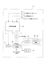
詳述すると、図2に示すように、水陸両用車21は、動力源であるエンジン31と、エンジン出力分配器32とを備えている。エンジン出力分配器32では、従来と同様の手動による陸上モード(陸上走行)と水上モード(水上航行)と中間モード(水際走行)のモード切り替え操作だけでなく、車両制御装置27から出力される陸上モード信号aと水上モード信号bと中間モード信号cによる自動的なモード切り替え操作によっても、エンジン11の出力を伝達する先を切り替えることができる。
Specifically, as shown in FIG. 2, the
詳細は後述するが、車両制御装置27では、水陸両用車21に装備されている荷重センサ41の出力(荷重検出値)に基づいて(即ち水陸両用車にかかる負荷値に基づいて)、モード切り替えのための陸上モード信号a、水上モード信号b又は中間モード信号cを、エンジン出力分配器32へ出力する。
Although details will be described later, the
車両制御装置27から陸上モード信号aが出力されると、この陸上モード信号aを入力したエンジン出力分配器32では、エンジン31の出力を、水陸両用車21に装備されているトランスミッション33へ伝える。従って、エンジン31の出力は、トランスミッション33を介して、水陸両用車21に装備されているスプロケット(動輪)34へ伝達される。その結果、エンジン31によってスプロケット34が回転駆動され、このスプロケット34によって装軌22が回転駆動される。このため、水陸両用車21は、装軌22によって陸上走行をすることができる。
When the land mode signal a is output from the
車両制御装置27から水上モード信号bが出力されると、この水上モード信号bを入力したエンジン出力分配器32では、エンジン31の出力をウォータジェット24へ伝える。このため、水陸両用車21は、ウォータジェット24によって水上航行をすることができる。
When the water mode signal b is output from the
車両制御装置27から中間モード信号cが出力されると、この中間モード信号cを入力したエンジン出力分配器12では、エンジン31の出力をトランスミッション33(即ち装軌22)とウォータジェット24の両方に伝える。このため、水陸両用車21は、装軌22とウォータジェット24の両方によって水際走行をすることができる。
When the intermediate mode signal c is output from the
次に、荷重センサ41の出力(荷重検出値)に基づいて実施される車両制御装置27のモード切り替え(各モード信号a,b,cの出力)について詳述する。
Next, mode switching (output of each mode signal a, b, c) of the
図3に示すように、本実施の形態例1で用いている荷重センサ41は歪みゲージであり、水陸両用車21にサスペンションとして装備されているトーションバー42に取り付けらている。トーションバー42の先端には連結部材43の一端が固定され、連結部材43の他端にはベアリング44を介して回転自在に水陸両用車21の車輪34が結合されている。荷重センサ(歪みゲージ)41はトーションバーの捩じれ(即ち歪み)を検出する。従って、トーションバー42に作用する水陸両用車21の荷重が変化すると、トーションバー42の捩じれ(即ち歪み)が変化し、これに伴って荷重センサ(歪みゲージ)41の出力が変化する。即ち、荷重センサ41により、陸上走行時、水上航行時及び水際走行時において装軌22(車輪34)にかかる水陸両用車21の荷重が検出される。
As shown in FIG. 3, the
図1(a)及び図1(b)に基づいて説明すると、水上25や水際26では水陸両用車21に対して浮力が働くため、水陸両用車21の走行・航行位置に応じて、荷重センサ41の出力(荷重検出値)が、図1(b)に例示するような変化をする。即ち、水陸両用車21が陸上26から水際26に達すると、水陸両用車21に浮力が働くため、荷重センサ41の出力は低下する。その後、水上25では水陸両用車21が水中に入る体積が増し、更に大きな浮力が水陸両用車21に働くため、荷重センサ41の出力が更に低下する。一方、水陸両用車21が水上25から水際26に達すると(水陸両用車21が水中に入る体積が減少すると)、水陸両用車21に働く浮力が小さくなるため、荷重センサ41の出力は増加する。その後、陸上23では水陸両用車21に浮力が働かなくなるため、荷重センサ41の出力が更に増加する。
Referring to FIGS. 1A and 1B, buoyancy is exerted on the
このような荷重センサ41の出力は、図1(a)に示すように車両制御装置27に入力される。
The output of such a
そして、車両制御装置27は、図1(b)に点線で示すような第1の荷重閾値S1と、第2の荷重閾値S2と、第3の荷重閾値S3と、第4の荷重閾値S4とを記憶しており、これらの荷重閾値S1〜S4と荷重センサ41の出力との比較結果に基づいて各モード信号a,b,cを出力する。第1の荷重閾値S1及び第2の荷重閾値S2は、図1(a)の左側に示すように水陸両用車21が、陸上23から水上25へ向かうときのモード切り替えのための閾値であり、第2の荷重閾値S2は第1の荷重閾値S1よりも小さな値である。第3の荷重閾値S3及び第4の荷重閾値S4は、図1(a)の右側に示すように水陸両用車21が、水上25から陸上23へ向かうときのモード切り替えのための閾値であり、第4の荷重閾値S4は第3の荷重閾値S3よりも大きな値である。なお、本実施の形態例1では、図1(b)に示すように第1の荷重閾値S1と第4の荷重閾値S4は同じ値とし、第2の荷重閾値S2と第3の荷重閾値S3は同じ値としているが、これに限定するものではなく、第1の荷重閾値S1と第4の荷重閾値S4を異なる値としてもよく、第2の荷重閾値S2と第3の荷重閾値S3を異なる値としてもよい。
Then, the
図1(a)及び図1(b)に示すように、車両制御装置27は、水陸両用車21が陸上モード(陸上走行)のとき、浮力により水陸両用車21の荷重が低下して荷重センサ41の出力が、第1の荷重閾値S1以下になった(即ち水際26に達した)と判定した場合には、陸上モードから中間モードへのモード切り替えをするために中間モード信号cを、エンジン出力分配器32へ出力する。その結果、この中間モード信号cに基づいてエンジン出力分配器32が、エンジン31の出力をトランスミッション33(装軌22)とウォータジェット24の両方に伝えるため、水陸両用車21は装軌22とウォータジェット24の両方による水際走行を行うことにより、水上25へ向かって水際26を下って行く。
As shown in FIGS. 1 (a) and 1 (b), the
また、車両制御装置27は、水陸両用車21が中間モード(水際走行)のとき、更に大きな浮力により水陸両用車21の荷重が更に低下して荷重センサ41の出力が、第2の荷重閾値S2以下になった(即ち水上25に達した)と判定した場合には、中間モードから水上モードへのモード切り替えをするために水上モード信号bを、エンジン出力分配器32へ出力する。その結果、この水上モード信号bに基づいてエンジン出力分配器32が、エンジン31の出力をウォータジェット24へ伝えることにより、水陸両用車21はウォータジェット24によって水上航行を行う。
In addition, when the
また、車両制御装置27は、水陸両用車21が水上モード(水上航行)のとき、浮力が小さくなり水陸両用車21の荷重が増加して荷重センサ41の出力が、第3の荷重閾値S3以上になった(即ち水際26に達した)と判定した場合には、水上モードから中間モードへのモード切り替えをするために中間モード信号cを、エンジン出力分配器32へ出力する。その結果、この中間モード信号cに基づいてエンジン出力分配器32が、エンジン31の出力をトランスミッション33(装軌22)とウォータジェット24の両方に伝えるため、水陸両用車21は装軌22とウォータジェット24の両方による水際走行を行うことにより、陸上23へ向かって水際26を上って行く。
Further, when the
また、車両制御装置27は、水陸両用車21が中間モード(水際走行)のとき、浮力が更に小さくなり水陸両用車21の荷重が更に増加して荷重センサ41の出力が、第4の荷重閾値S4以上になった(即ち陸上23に達した)と判定した場合には、中間モードから陸上モードへのモード切り替えをするために陸上モード信号aを、エンジン出力分配器32へ出力する。その結果、この陸上モード信号aに基づいてエンジン出力分配器32が、エンジン31の出力を装軌22へ伝えることにより、水陸両用車21は装軌22による陸上走行を行う。
Further, when the
次に、中間モード(水際走行)において、装軌22の空回りが発生したときの車両制御装置27によるエンジン出力制御について説明する。
Next, the engine output control by the
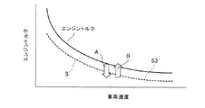
図2に示すように、車両制御装置27では、水陸両用車21に装備されている車両速度センサ51の出力(車両速度検出値)と、水陸両用車21に装備されているエンジン回転トルクセンサ52の出力(エンジン回転トルク検出値)も入力する。また、車両制御装置27は、図4に点線で示すようなエンジン回転トルク閾値Sも記憶している。図4に実線で示すようにエンジン31の回転トルクは、水陸両用車21の車両速度が増加するにしたがって減少する。このため、車両制御装置27に記憶されているエンジン回転トルク閾値Sも、図4に点線で示すように水陸両用車21の車両速度(車両速度センサ51の出力)が増加するにしたがって減少するように設定されている。
As shown in FIG. 2, in the
車両制御装置27では、水陸両用車21が中間モード(水際走行)のとき、車両速度センサ51の出力(車両速度検出値)に対応した値のエンジン回転トルク閾値Sと、エンジン回転トルクセンサ52の出力とを比較する。そして、車両制御装置27は、エンジン回転トルクセンサ52の出力が当該エンジン回転トルク閾値S以下になった(即ち装軌22が空回りしている)と判定した場合には、図2に示すようにエンジン31へエンジン出力増加信号dを出力する。つまり、装軌22が空回りするとエンジン31に対する負荷が軽減されることになるため、エンジン31の回転トルクが減少する。従って、エンジン回転トルクセンサ52の出力がエンジン回転トルク閾値S以下になった場合、即ち車両速度(車両速度センサ51の出力)が増加していないにも関わらず、図4に矢印Aで示すようにエンジン31の回転トルク(エンジン回転トルクセンサ52の出力)が減少した場合には、装軌22が空回りしていると判定することができる。
In the
車両制御装置27からエンジン31へエンジン出力増加信号dが出力されると、このエンジン出力増加信号dに基づいてエンジン31の出力が増加するため、装軌22の空回りによって減少した水陸両用車21の車両速度が増加する(即ち車両速度が安定する)。つまり、中間モードでは装軌22とウォータジェット24の両方による水際走行を行っており、装軌22が空回りしたとしても、ウォータジェット24の推進力が得られる。従って、エンジン出力増加信号dに基づいてエンジン31の出力が増加すると、ウォータジェット24の推進力が増加するため、装軌22の空回りによって減少した水陸両用車21の車両速度が増加して安定する。このとき、図4に矢印Bで示すようにエンジン31の回転トルクは上昇する。
When the engine output increase signal d is output from the
以上のように、本実施の形態例1における水陸両用車21の車両制御装置27によれば、水陸両用車21が陸上23から水上25に向かうときの陸上モードから水際モードへのモード切り替えを行うための中間モード信号c及び水際モードから水上モードへのモード切り替えを行うための水上モード信号b、又は、水上25から陸上23へ向かうときの水上モードから水際モードへのモード切り替えを行うための中間モード信号c及び水際モードから陸上モードへのモード切り替えを行うための陸上モード信号aを、水陸両用車21にかかる負荷値(荷重センサ41の出力である荷重検出値)に基づいてエンジン出力分配器32へ出力することを特徴としている。
As described above, according to the
具体的には、陸上モード信号aに基づいてエンジン出力分配器32がエンジン31の出力を装軌22へ伝えることにより装軌22によって陸上23を走行する陸上走行と、水上モード信号bに基づいてエンジン出力分配器32がエンジン31の出力をウォータジェット24へ伝えることによりウォータジェット24によって水上25を航行する水上航行と、中間モード信号cに基づいてエンジン出力分配器32がエンジン31の出力を装軌22とウォータジェット24へ伝えることにより装軌22とウォータジェット24によって水際を走行する水際走行とを行うことが可能な水陸両用車21の車両制御装置27であって、水陸両用車21の荷重を検出する荷重センサ41の出力(荷重検出値)と、水陸両用車21が陸上23から水上25へ向かうときのモード切り替えのための閾値である第1の荷重閾値S1及び第2の荷重閾値S2、及び、水陸両用車21が水上25から陸上23へ向かうときのモード切り替えのための閾値である第3の荷重閾値S3及び第4の荷重閾値S4とを比較し、水陸両用車21が陸上モードのとき、荷重センサ41の出力が第1の荷重閾値S1以下になったと判定した場合には、陸上モードから中間モードへのモード切り替えをするために中間モード信号cを、エンジン出力分配器32へ出力し、水陸両用車21が中間モードのとき、荷重センサ41の出力が第2の荷重閾値S2以下になったと判定した場合には、中間モードから水上モードへのモード切り替えをするために水上モード信号bを、エンジン出力分配器32へ出力し、水陸両用車21が水上モードのとき、荷重センサ41の出力が第3の荷重閾値S3以上になったと判定した場合には、水上モードから中間モードへのモード切り替えをするために中間モード信号cを、エンジン出力分配器32へ出力し、水陸両用車21が中間モードのとき、荷重センサ41の出力が第4の荷重閾値S4以上になったと判定した場合には、中間モードから陸上モードへのモード切り替えをするために陸上モード信号aを、エンジン出力分配器32へ出力することを特徴としている。
Specifically, the
このため、車両制御装置27によって水陸両用車21のモード切り替えを自動的に行うことができる。従って、水陸両用車21の操作に習熟していない操作者が水陸両用車21を操作する場合や、水陸両用車21を操作中の視界が悪い場合にも、水陸両用車21のモード切り替えをするタイミングを誤ってしまうおそれがない。
For this reason, the
また、本実施の形態例1の水陸両用車21の車両制御装置27によれば、水陸両用車21が中間モードのとき、エンジン31の回転トルクを検出するエンジン回転トルクセンサ52の出力と、水陸両用車21の車両速度を検出する車両速度センサ51の出力に応じて設定するエンジン回転トルク閾値Sとを比較し、エンジン回転トルクセンサ52の出力が、車両速度センサ51の出力に対応した値のエンジン回転トルク閾値S以下になって装軌22が空回りしていると判定した場合には、エンジン31へエンジン出力増加信号dを出力することを特徴としているため、中間モードのときに水陸両用車21の装軌22が空回りしても、水陸両用車21の車両速度を安定させることができる。
Further, according to the
なお、これに限定するものではなく、水陸両用車21が中間モードのとき、エンジン出力分配器32と装軌22との間に介設されているトランスミッション33の回転トルクを検出する回転トルクセンサの出力と、水陸両用車21の車両速度を検出する車両速度センサ51の出力に応じて設定する回転トルク閾値とを比較し、前記回転トルクセンサの出力が、車両速度センサ51の出力に対応した値の回転トルク閾値以下になって装軌22が空回りしていると判定した場合には、トランスミッションへ減速比変更信号を出力するようにしてもよい。この減速比変更信号に基づいてトランスミッション33の減速比を変更することにより、中間モードのときに水陸両用車21の装軌22が空回りしても、水陸両用車21の車両速度を安定させることができる。これは、トランスミッション33の回転トルクが下がったとき(装軌22が空回りしたとき)、回転数を落として回転トルクを上げる(力強さを持たせる)ことで出力(回転数×回転トルク)を結果的に上げることが可能になるためである。
However, the present invention is not limited to this. When the
<実施の形態例2>
図5に基づき、本発明の実施の形態例2に係る水陸両用車21の車両制御装置27について説明する。なお、水陸両用車21の装備や水陸両用車21の陸上走行時、水上航行時及び水際走行時の様子などについては上記実施の形態例1の場合と同様である(図1(a)参照)。本実施の形態例2では、上記実施の形態例1で用いた水陸両用車21の荷重の代わりに水陸両用車21の傾斜角(ピッチ角)に基づいて(水際又は海岸線に関わる計測値に基づいて)、車両制御装置27による自動的なモード切り替えを行う。
<
Based on FIG. 5, the
詳述すると、図5に示すように、本実施の形態例2の車両制御装置27では、水陸両用車21に装備されている車両傾斜角センサ61の出力(車両傾斜角検出値)を入力する。車両傾斜角センサ61は、水陸両用車21の車体前後方向(前側)が上方や下方に傾斜したときの傾斜角(ピッチ角)を検出して出力するセンサである。ここでは車両傾斜角センサ61としてジャイロが用いられている。
More specifically, as shown in FIG. 5, the
車両制御装置27は、第1の車両傾斜角閾値S11と、第2の車両傾斜角閾値S12と、第3の車両傾斜角閾値S13と、第4の車両傾斜角閾値S14とを記憶している。第1の車両傾斜角閾値S11及び第2の車両傾斜角閾値S12は、図1(a)の左側に示すように水陸両用車21が、陸上23から水上25へ向かうときのモード切り替えのための閾値である。第3の車両傾斜角閾値S13及び第4の車両傾斜角閾値S14は、図1(a)の右側に示すように水陸両用車21が、水上25から陸上23へ向かうときのモード切り替えのための閾値である。
The
図1(a)に示すように、陸上23を走行していた水陸両用車21が水際26に達すると、水陸両用車21の前側が下方へ傾く。従って、車両制御装置27は、水陸両用車21が陸上モード(陸上走行)のとき、水陸両用車21の前側の下方への傾斜角が大きくなって車両傾斜角センサ61の出力が、第1の車両傾斜角閾値S11以上になった(即ち水際26に達した)と判定した場合には、陸上モードから中間モードへのモード切り替えをするために中間モード信号cを、エンジン出力分配器32へ出力する。その結果、この中間モード信号cに基づいてエンジン出力分配器32が、エンジン31の出力を、装軌22とウォータジェット24の両方に伝えるため、水陸両用車21は装軌22とウォータジェット24の両方による水際走行を行うことにより、水上25へ向かって水際26を下って行く。
As shown in FIG. 1A, when the
また、水際26を走行していた水陸両用車21が水上25に達すると(水深が深くなると)、水陸両用車21の前側の下方への傾斜角が小さくなる。従って、車両制御装置27は、水陸両用車21が中間モード(水際走行)のとき、水陸両用車21の前側の下方への傾斜角が小さくなって車両傾斜角センサ61の出力が、第2の車両傾斜角閾値S12以下になった(即ち水上25に達した:水深が深くなった)と判定した場合には、中間モードから水上モードへのモード切り替えをするために水上モード信号bを、エンジン出力分配器32へ出力する。その結果、この水上モード信号bに基づいてエンジン出力分配器32が、エンジン31の出力をウォータジェット24へ伝えることにより、水陸両用車21はウォータジェット24によって水上航行を行う。なお、水上25では水陸両用車21の傾斜が大きく変動することはなく、水陸両用車21はほぼ水平である。
Further, when the
また、水上25を航行していた水陸両用車21が水際26に達すると、水陸両用車21の前側の上方への傾斜角が大きくなる。従って、車両制御装置27は、水陸両用車21が水上モード(水上航行)のとき、水陸両用車21の前側の上方への傾斜角が大きくなって車両傾斜角センサ61の出力が、第3の車両傾斜角閾値S13以上になった(即ち水際26に達した)と判定した場合には、水上モードから中間モードへのモード切り替えをするために中間モード信号cを、エンジン出力分配器32へ出力する。その結果、この中間モード信号cに基づいてエンジン出力分配器32が、エンジン31の出力を装軌22とウォータジェット24の両方に伝えるため、水陸両用車21は装軌22とウォータジェット24の両方による水際走行を行うことにより、陸上23へ向かって水際26を上って行く。
Further, when the
また、水際26を走行していた水陸両用車21が陸上23に達すると、水陸両用車21の前側の上方への傾斜角が小さくなる。従って、車両制御装置27は、水陸両用車21が中間モード(水際走行)のとき、水陸両用車21の前側の上方への傾斜角が小さくなって車両傾斜角センサ61の出力が、第4の車両傾斜角閾値S14以下になった(即ち陸上23に達した)と判定した場合には、中間モードから陸上モードへのモード切り替えをするために陸上モード信号aを、エンジン出力分配器32へ出力する。その結果、この陸上モード信号aに基づいてエンジン出力分配器32が、エンジン31の出力を装軌22へ伝えることにより、水陸両用車21は装軌22による陸上走行を行う。
In addition, when the
なお、中間モード(水際走行)において、装軌22の空回りが発生したときの車両制御装置27によるエンジン出力制御については、上記実施の形態例1の場合と同様であり、ここでの詳細な説明は省略する。
Note that the engine output control by the
以上のように、本実施の形態例2における水陸両用車21の車両制御装置27によれば、水陸両用車21が陸上23から水上25に向かうときの陸上モードから水際モードへのモード切り替えを行うための中間モード信号c及び水際モードから水上モードへのモード切り替えを行うための水上モード信号b、又は、水上25から陸上23へ向かうときの水上モードから水際モードへのモード切り替えを行うための中間モード信号c及び水際モードから陸上モードへのモード切り替えを行うための陸上モード信号aを、水際又は海岸線に関わる計測値(車両傾斜角センサ61の出力である傾斜角検出値)に基づいてエンジン出力分配器32へ出力することを特徴としている。
As described above, according to the
具体的には、陸上モード信号aに基づいてエンジン出力分配器32がエンジン31の出力を装軌22へ伝えることにより装軌22によって陸上23を走行する陸上走行と、水上モード信号bに基づいてエンジン出力分配器32がエンジン31の出力をウォータジェット24へ伝えることによりウォータジェット24によって水上を航行する水上航行と、中間モード信号cに基づいてエンジン出力分配器32がエンジン31の出力を装軌22とウォータジェット24へ伝えることにより装軌22とウォータジェット24って水際26を走行する水際走行とを行うことが可能な水陸両用車21の車両制御装置27であって、水陸両用車21の前側が上方や下方へ傾斜したときの傾斜角を検出する車両傾斜角センサ61の出力と、水陸両用車21が陸上23から水上25へ向かうときのモード切り替えのための閾値である第1の車両傾斜角閾値S11及び第2の車両傾斜角閾値S12、及び、水陸両用車21が水上25から陸上23へ向かうときのモード切り替えのための閾値である第3の車両傾斜角閾値S13及び第4の車両傾斜角閾値S14とを比較し、水陸両用車21が陸上モードのとき、車両傾斜角センサ61の出力が第1の車両傾斜角閾値S11以上になったと判定した場合には、陸上モードから中間モードへのモード切り替えをするために中間モード信号cを、エンジン出力分配器32へ出力し、水陸両用車21が中間モードのとき、車両傾斜角センサ61の出力が第2の車両傾斜角閾値S12以下になったと判定した場合には、中間モードから水上モードへのモード切り替えをするために水上モード信号cを、エンジン出力分配器32へ出力し、水陸両用車21が水上モードのとき、車両傾斜角センサ61の出力が第3の車両傾斜角閾値S13以上になったと判定した場合には、水上モードから中間モードへのモード切り替えをするために中間モード信号cを、エンジン出力分配器32へ出力し、水陸両用車21が中間モードのとき、車両傾斜角センサ61の出力が第4の車両傾斜角閾値S14以下になったと判定した場合には、中間モードから陸上モードへのモード切り替えをするために陸上モード信号aを、エンジン出力分配器32へ出力することを特徴としている。
Specifically, the
このため、車両制御装置2によって水陸両用車21のモード切り替えを自動的に行うことができる。従って、水陸両用車21の操作に習熟していない操作者が水陸両用車21を操作する場合や、水陸両用車21を操作中の視界が悪い場合にも、水陸両用車21のモード切り替えをするタイミングを誤ってしまうおそれがない。
For this reason, the
また、本実施の形態例2の水陸両用車21の車両制御装置27でも、上記実施の形態例1と同様に、水陸両用車21が中間モードのとき、エンジン31の回転トルクを検出するエンジン回転トルクセンサ52の出力(又はエンジン出力分配器32と装軌22との間に介設されているトランスミッション33の回転トルクを検出するトランスミッション回転トルクセンサの出力)と、水陸両用車21の車両速度を検出する車両速度センサ51の出力に応じて設定するエンジン回転トルク閾値S(又はトランスミッション回転トルク閾値S)とを比較し、エンジン回転トルクセンサ52の出力(又はトランスミッション回転トルクセンサの出力)が、車両速度センサ51の出力に対応した値のエンジン回転トルク閾値S以下(又はトランスミッション回転トルク閾値S以下)になって装軌22が空回りしていると判定した場合には、エンジン31へエンジン出力増加信号dを出力する(トランスミッション33へ減速比変更信号を出力する)ことを特徴としているため、中間モードのときに水陸両用車21の装軌22が空回りしても、水陸両用車21の車両速度を安定させることができる。
Further, in the
<実施の形態例3>
図6に基づき、本発明の実施の形態例3に係る水陸両用車21の車両制御装置27について説明する。なお、水陸両用車21の装備や水陸両用車21の陸上走行時、水上航行時及び水際走行時の様子などについては上記実施の形態例1の場合と同様である(図1(a)参照)。本実施の形態例3では、上記実施の形態例1の水陸両用車21で用いた荷重の代わりにエンジン31の回転トルクに基づいて(即ち水陸両用車にかかる負荷値に基づいて)、車両制御装置27による自動的なモード切り替えを行う。
<
Based on FIG. 6, the
詳述すると、図6に示すように、本実施の形態例3の車両制御装置27では、水陸両用車21に装備されているエンジン回転トルクセンサ52の出力(エンジン回転トルク検出値)と車両速度センサ51の出力(車両速度検出値)を、モード切り替えにも利用する。
More specifically, as shown in FIG. 6, in the
車両制御装置27は、上記実施の形態例1で述べたエンジン回転トルク閾値S(中間モードにおいて装軌22の空転を検出すための閾値)だけでなく、第1のエンジン回転トルク閾値S21と、第2のエンジン回転トルク閾値S22と、第3のエンジン回転トルク閾値S23と、第4のエンジン回転トルク閾値S24も記憶している。これらの第1,第2,第3及び第4のエンジン回転トルク閾値S21,S22,S23,S24は、エンジン回転トルク閾値Sと同様(図4参照)、水陸両用車21の車両速度(車両速度センサ51の出力)が増加するにしたがって、減少するように設定されている。
The
また、第1のエンジン回転トルク閾値S21及び第2のエンジン回転トルク閾値S22は、図1(a)の左側に示すように水陸両用車21が、陸上23から水上25へ向かうときのモード切り替えのための閾値であり、第2のエンジン回転トルク閾値S22は第1のエンジン回転トルク閾値S21よりも小さな値である。第3のエンジン回転トルク閾値S23及び第4のエンジン回転トルク閾値S24は、図1(a)の右側に示すように水陸両用車21が、水上25から陸上23へ向かうときのモード切り替えのための閾値であり、第4のエンジン回転トルク閾値S24は第3のエンジン回転トルク閾値S23よりも大きな値である。
The first engine rotational torque threshold value S21 and the second engine rotational torque threshold value S22 are used for mode switching when the
図1(a)に示すように、陸上23を走行していた水陸両用車21が水際26に達すると、水陸両用車21に浮力が働くため、エンジン31の回転トルクが低下する。従って、車両制御装置27は、水陸両用車21が陸上モード(陸上走行)のとき、車両速度センサ51の出力(車両速度検出値)に対応した値の第1のエンジン回転トルク閾値S21と、エンジン回転トルクセンサ52の出力とを比較する。そして、車両制御装置27は、エンジン31の回転トルクが低下してエンジン回転トルクセンサ52の出力が、当該第1のエンジン回転トルク閾値S21以下になった(即ち水際26に達した)と判定した場合には、陸上モードから中間モードへのモード切り替えをするために中間モード信号cを、エンジン出力分配器32へ出力する。その結果、この中間モード信号cに基づいてエンジン出力分配器32が、エンジン31の出力を装軌22とウォータジェット24の両方に伝えるため、水陸両用車21は装軌22とウォータジェット24の両方による水際走行を行うことにより、水上25へ向かって水際26を下って行く。
As shown in FIG. 1A, when the
また、水際26を走行していた水陸両用車21が水上25に達すると(水深が深くなって水陸両用車21が水中に入る体積が増すと)、水陸両用車21に更に大きな浮力が働くため、エンジン31の回転トルクが更に低下する。従って、車両制御装置27は、水陸両用車21が中間モード(水際走行)のとき、車両速度センサ51の出力に対応した値の第2のエンジン回転トルク閾値S22と、エンジン回転トルクセンサ52の出力とを比較する。そして、車両制御装置27は、エンジン31の回転トルクが更に低下してエンジン回転トルクセンサ52の出力が、当該第2のエンジン回転トルク閾値S22以下になった(即ち水上25に達した)と判定した場合には、中間モードから水上モードへのモード切り替えをするために水上モード信号bを、エンジン出力分配器32へ出力する。その結果、この水上モード信号bに基づいてエンジン出力分配器32が、エンジン31の出力をウォータジェット24へ伝えることにより、水陸両用車21はウォータジェット24によって水上航行を行う。
In addition, when the
また、水上25を航行していた水陸両用車21が水際26に達すると、水深が浅くなって装軌22が水底に接することから、エンジン31の回転トルクが増加する。従って、車両制御装置27は、水陸両用車21が水上モード(水上航行)のとき、車両速度センサ51の出力に対応した値の第3のエンジン回転トルク閾値S23と、エンジン回転トルクセンサ52の出力とを比較する。そして、車両制御装置27は、エンジン31の回転トルクが増加してエンジン回転トルクセンサ52の出力が、当該第3のエンジン回転トルク閾値S23以上になった(即ち水際26に達した)と判定した場合には、水上モードから中間モードへのモード切り替えをするために中間モード信号cを、エンジン出力分配器32へ出力する。その結果、この中間モード信号cに基づいてエンジン出力分配器32が、エンジン31の出力を装軌22とウォータジェット24の両方に伝えるため、水陸両用車21は装軌22とウォータジェット24の両方による水際走行を行うことにより、陸上23へ向かって水際26を上って行く。
Further, when the
また、水際26を走行していた水陸両用車21が陸上23に達すると、水陸両用車21に浮力が働かなくなるため、エンジン31の回転トルクが更に増加する。従って、車両制御装置27は、水陸両用車21が中間モード(水際走行)のとき、車両速度センサ51の出力に対応した値の第4のエンジン回転トルク閾値S24と、エンジン回転トルクセンサ52の出力とを比較する。そして、車両制御装置27は、エンジン31の回転トルクが更に増加してエンジン回転トルクセンサ52の出力が、当該第4のエンジン回転トルク閾値S24以上になった(即ち陸上23に達した)と判定した場合には、中間モードから陸上モードへのモード切り替えをするために陸上モード信号aを、エンジン出力分配器32へ出力する。その結果、この陸上モード信号aに基づいてエンジン出力分配器32が、エンジン31の出力を装軌22へ伝えることにより、水陸両用車21は装軌22による陸上走行を行う。
Further, when the
なお、中間モード(水際走行)において、装軌22の空回りが発生したときの車両制御装置27によるエンジン出力制御については、上記実施の形態例1の場合と同様であり、ここでの詳細な説明は省略する。
また、上記ではエンジン31の回転トルクを用いているが、これに代えてトランスミッション33の回転トルクを用いてもよい。
Note that the engine output control by the
In the above description, the rotational torque of the
以上のように、本実施の形態例3における水陸両用車21の車両制御装置27によれば、水陸両用車21が陸上23から水上25に向かうときの陸上モードから水際モードへのモード切り替えを行うための中間モード信号c及び水際モードから水上モードへのモード切り替えを行うための水上モード信号b、又は、水上25から陸上23へ向かうときの水上モードから水際モードへのモード切り替えを行うための中間モード信号c及び水際モードから陸上モードへのモード切り替えを行うための陸上モード信号aを、水陸両用車21にかかる負荷値(エンジン回転トルクセンサ52の出力であるエンジン回転トルク検出値又はトランスミッション回転トルクセンサの出力であるトランスミッション回転トルク検出値)に基づいてエンジン出力分配器32へ出力することを特徴としている。
As described above, according to the
具体的には、陸上モード信号aに基づいてエンジン出力分配器32がエンジン31の出力を装軌22へ伝えることにより装軌22によって陸上23を走行する陸上走行と、水上モード信号bに基づいてエンジン出力分配器32がエンジン31の出力をウォータジェット24へ伝えることによりウォータジェット24によって水上25を航行する水上航行と、中間モード信号cに基づいてエンジン出力分配器32がエンジン31の出力を装軌22とウォータジェット24へ伝えることにより装軌22とウォータジェット24によって水際26を走行する水際走行とを行うことが可能な水陸両用車21の車両制御装置27であって、エンジン31の回転トルクを検出するエンジン回転トルクセンサ52の出力(又はエンジン出力分配器32と装軌22との間に介設されているトランスミッション33の回転トルクを検出するトランスミッション回転トルクセンサの出力)と、水陸両用車21が陸上23から水上25へ向かうときのモード切り替えのための閾値であり、且つ、水陸両用車21の車両速度を検出する車両速度センサ51の出力に応じて設定する第1のエンジン回転トルク閾値S21(又は第1のトランスミッション回転トルク閾値S21)及び第2のエンジン回転トルク閾値S22(又は第2のトランスミッション回転トルク閾値S22)、及び、水陸両用車21が水上25から陸上23へ向かうときのモード切り替えのための閾値であり、且つ、車両速度センサ51の出力に応じて設定する第3のエンジン回転トルク閾値S23(又は第3のトランスミッション回転トルク閾値S23)及び第4のエンジン回転トルク閾値S24(又は第4のトランスミッション回転トルク閾値S24)とを比較し、水陸両用車21が陸上モードのとき、エンジン回転トルクセンサ52の出力(又はトランスミッション回転トルクセンサの出力)が、車両速度センサ51の出力に対応した値の第1のエンジン回転トルク閾値S21以下(又は第1のトランスミッション回転トルク閾値S21以下)になったと判定した場合には、陸上モードから中間モードへのモード切り替えをするために中間モード信号cを、エンジン出力分配器32へ出力し、水陸両用車21が中間モードのとき、エンジン回転トルクセンサ52の出力(又はトランスミッション回転トルクセンサの出力)が、車両速度センサ51の出力に対応した値の第2のエンジン回転トルク閾値S22以下(又は第2のトランスミッション回転トルク閾値S22以下)になったと判定した場合には、中間モードから水上モードへのモード切り替えをするために水上モード信号bを、エンジン出力分配器32へ出力し、水陸両用車21が水上モードのとき、エンジン回転トルクセンサ52の出力が、車両速度センサ51の出力に対応した値の第3のエンジン回転トルク閾値S23以上(又は第3のトランスミッション回転トルク閾値S23以上)になったと判定した場合には、水上モードから中間モードへのモード切り替えをするために中間モード信号cを、エンジン出力分配器32へ出力し、水陸両用車21が中間モードのとき、エンジン回転トルクセンサ52の出力が、車両速度センサ51の出力に対応した値の第4のエンジン回転トルク閾値S24以上(又は第4のトランスミッション回転トルク閾値S24以上)になったと判定した場合には、中間モードから陸上モードへのモード切り替えをするために陸上モード信号aを、エンジン出力分配器32へ出力することを特徴としている。
Specifically, the
このため、車両制御装置27によって水陸両用車21のモード切り替えを自動的に行うことができる。従って、水陸両用車21の操作に習熟していない操作者が水陸両用車21を操作する場合や、水陸両用車21を操作中の視界が悪い場合にも、水陸両用車21のモード切り替えをするタイミングを誤ってしまうおそれがない。
For this reason, the
また、本実施の形態例3の水陸両用車21の車両制御装置27でも、上記実施の形態例1と同様に、水陸両用車21が中間モードのとき、エンジン回転トルクセンサ52の出力(又はエンジン出力分配器32と装軌22との間に介設されているトランスミッション33の回転トルクを検出するトランスミッション回転トルクセンサの出力)と、車両速度センサ51の出力に応じて設定するエンジン回転トルク閾値S(第5のエンジン回転トルク閾値)(又はトランスミッション回転トルク閾値S(第5のトランスミッション回転トルク閾値))とを比較し、エンジン回転トルクセンサ52の出力(又はトランスミッション回転トルクセンサの出力)が、車両速度センサ51の出力に対応した値のエンジン回転トルク閾値S(第5のエンジン回転トルク閾値)以下(又はトランスミッション回転トルク閾値S(第5のトランスミッション回転トルク閾値)以下)になって装軌22が空回りしていると判定した場合には、エンジン31へエンジン出力増加信号dを出力(トランスミッション33へ減速比変更信号を出力する)することを特徴としているため、中間モードのときに水陸両用車21の装軌22が空回りしても、水陸両用車21の車両速度を安定させることができる。
Further, in the
<実施の形態例4>
図7に基づき、本発明の実施の形態例4に係る水陸両用車21の車両制御装置27について説明する。なお、水陸両用車21の装備や水陸両用車21の陸上走行時、水上航行時及び水際走行時の様子などについては上記実施の形態例1の場合と同様である(図1(a)参照)。本実施の形態例4では、上記実施の形態例1で用いた水陸両用車21の荷重の代わりに水深に基づいて(水際又は海岸線に関わる計測値に基づいて)、車両制御装置27による自動的なモード切り替えを行う。
<Embodiment 4>
Based on FIG. 7, the
詳述すると、図5に示すように、本実施の形態例2の車両制御装置27では、水陸両用車21に装備されている水深計71の出力(水深計測値)を入力する。水深計71は図1(a)に示す水際26や水上25における水深を計測して出力するセンサである。
More specifically, as shown in FIG. 5, the
車両制御装置27は、第1の水深閾値S31と、第2の水深閾値S32と、第3の水深閾値S33と、第4の水深閾値S34とを記憶している。第1の水深閾値S31及び第2の水深閾値S32は、図1(a)の左側に示すように水陸両用車21が、陸上23から水上25へ向かうときのモード切り替えのための閾値であり、第2の水深閾値S32は第1の水深閾値S31よりも大きな値である。第3の水深閾値S33及び第4の水深閾値S34は、図1(a)の右側に示すように水陸両用車21が、水上25から陸上23へ向かうときのモード切り替えのための閾値であり、第4の水深閾値S34は第3の水深閾値S33よりも小さな値である。なお、第1の水深閾値S31と第4の水深閾値S34は同じ値でも、異なる値でもよく、第2の水深閾値S32と第3の水深閾値S33は同じ値でも、異なる値でもよい。
The
図1(a)に示すように、陸上23を走行していた水陸両用車21が水際26に達すると、水深計71によって、水際26における水深が計測されるようになる。従って、車両制御装置27は、水陸両用車21が陸上モード(陸上走行)のとき、水深計71の出力が第1の水深閾値S31以上になった(即ち水際26に達した)と判定した場合には、陸上モードから中間モードへのモード切り替えをするために中間モード信号cを、エンジン出力分配器32へ出力する。その結果、この中間モード信号cに基づいてエンジン出力分配器32が、エンジン31の出力をトランスミッション33(装軌22)とウォータジェット24の両方に伝えるため、水陸両用車21は装軌22とウォータジェット24の両方による水際走行を行うことにより、水上25へ向かって水際26を下って行く。
As shown in FIG. 1A, when the
また、水際26を走行していた水陸両用車21が水上25に達すると、水深計71によって計測される水深が深くなる。従って、車両制御装置27は、水陸両用車21が中間モード(水際走行)のとき、水深計71の出力が第2の水深閾値S32以上になった(即ち水上25に達した:水深が深くなった)と判定した場合には、中間モードから水上モードへのモード切り替えをするために水上モード信号bを、エンジン出力分配器32へ出力する。その結果、この水上モード信号bに基づいてエンジン出力分配器32が、エンジン31の出力をウォータジェット24へ伝えることにより、水陸両用車21はウォータジェット24によって水上航行を行う。
Further, when the
また、水上25を航行していた水陸両用車21が水際26に達すると、水深計71によって計測される水深が浅くなる。従って、車両制御装置27は、水陸両用車21が水上モード(水上航行)のとき、水深計71の出力が第3の水深閾値S33以下になった(即ち水際26に達した)と判定した場合には、水上モードから中間モードへのモード切り替えをするために中間モード信号cを、エンジン出力分配器32へ出力する。その結果、この中間モード信号cに基づいてエンジン出力分配器32が、エンジン31の出力を装軌22とウォータジェット24の両方に伝えるため、水陸両用車21は装軌22とウォータジェット24の両方による水際走行を行うことにより、陸上23へ向かって水際26を上って行く。
Further, when the
また、水際26を走行していた水陸両用車21が陸上23に達すると、水深計71によって計測される水深が更に浅くなる。従って、車両制御装置27は、水陸両用車21が中間モード(水際走行)のとき、水深計71の出力が第4の水深閾値S34以下になった(即ち陸上23に達した)と判定した場合には、中間モードから陸上モードへのモード切り替えをするために陸上モード信号aを、エンジン出力分配器32へ出力する。その結果、この陸上モード信号aに基づいてエンジン出力分配器32が、エンジン31の出力を装軌22へ伝えることにより、水陸両用車21は装軌22による陸上走行を行う。
Further, when the
或いは、水陸両用車21が陸上23に上陸して水が無くなると、水深計71は水深計測不能になるため、中間モードから陸上モードへのモード切り替える際には、上記のように水深計71の出力と第4の荷重閾値S34とを比較する代わりに、水深計71が水深計測不能になったか否かを判定するようにしてもよい。即ち、車両制御装置27は、水陸両用車21が中間モード(水際走行)のとき、水深計71が水深計測不能になった(即ち陸上23に達した(上陸した))と判定した場合には、中間モードから陸上モードへのモード切り替えをするために陸上モード信号aを、エンジン出力分配器32へ出力する。その結果、この陸上モード信号aに基づいてエンジン出力分配器32が、エンジン31の出力を装軌22へ伝えることにより、水陸両用車21は装軌22による陸上走行を行う。
Alternatively, when the
なお、中間モード(水際走行)において、装軌22の空回りが発生したときの車両制御装置27によるエンジン出力制御については、上記実施の形態例1の場合と同様であり、ここでの詳細な説明は省略する。
Note that the engine output control by the
以上のように、本実施の形態例4における水陸両用車21の車両制御装置27によれば、水陸両用車21が陸上23から水上25に向かうときの陸上モードから水際モードへのモード切り替えを行うための中間モード信号c及び水際モードから水上モードへのモード切り替えを行うための水上モード信号b、又は、水上25から陸上23へ向かうときの水上モードから水際モードへのモード切り替えを行うための中間モード信号c及び水際モードから陸上モードへのモード切り替えを行うための陸上モード信号aを、水際又は海岸線に関わる計測値(水深計71の出力である水深計測値)に基づいてエンジン出力分配器32へ出力することを特徴としている。
As described above, according to the
具体的には、陸上モード信号aに基づいてエンジン出力分配器32がエンジン31の出力を装軌22へ伝えることにより装軌22によって陸上23を走行する陸上走行と、水上モード信号bに基づいてエンジン出力分配器32がエンジン31の出力をウォータジェット24へ伝えることによりウォータジェット24によって水上25を航行する水上航行と、中間モード信号cに基づいてエンジン出力分配器32がエンジン31の出力を装軌22とウォータジェット24へ伝えることにより装軌22とウォータジェット24によって水際を走行する水際走行とを行うことが可能な水陸両用車21の車両制御装置27であって、水際26や水上25における水深を計測する水深計71の出力と、水陸両用車21が陸上23から水上25へ向かうときのモード切り替えのための閾値である第1の水深閾値S31及び第2の水深閾値S32、及び、水陸両用車21が水上25から陸上23へ向かうときのモード切り替えのための閾値である第3の水深閾値S33及び第4の水深閾値S34とを比較し、又は、水深計71の出力と第4の荷重閾値S34とを比較する代わりに、水深計71が水深計測不能になったか否かを判定し、水陸両用車21が陸上モードのとき、水深計71の出力が第1の水深閾値S31以上になったと判定した場合には、陸上モードから中間モードへのモード切り替えをするために中間モード信号cを、エンジン出力分配器32へ出力し、水陸両用車21が中間モードのとき、水深計71の出力が第2の水深閾値S32以上になったと判定した場合には、中間モードから水上モードへのモード切り替えをするために水上モード信号bを、エンジン出力分配器32へ出力し、水陸両用車21が水上モードのとき、水深計71の出力が第3の水深閾値S33以下になったと判定した場合には、水上モードから中間モードへのモード切り替えをするために中間モード信号cを、エンジン出力分配器32へ出力し、水陸両用車21が中間モードのとき、水深計71の出力が第4の水深閾値S34以下になったと判定した場合、又は、水深計71が水深計測不能になったと判定した場合には、中間モードから陸上モードへのモード切り替えをするために陸上モード信号aを、エンジン出力分配器32へ出力することを特徴としている。
Specifically, the
このため、車両制御装置27によって水陸両用車21のモード切り替えを自動的に行うことができる。従って、水陸両用車21の操作に習熟していない操作者が水陸両用車21を操作する場合や、水陸両用車21を操作中の視界が悪い場合にも、水陸両用車21のモード切り替えをするタイミングを誤ってしまうおそれがない。
For this reason, the
また、本実施の形態例4の水陸両用車21の車両制御装置27でも、上記実施の形態例1と同様に、水陸両用車21が中間モードのとき、エンジン31の回転トルクを検出するエンジン回転トルクセンサ52の出力(又はエンジン出力分配器32と装軌22との間に介設されているトランスミッション33の回転トルクを検出するトランスミッション回転トルクセンサの出力)と、水陸両用車21の車両速度を検出する車両速度センサ51の出力に応じて設定するエンジン回転トルク閾値S(又はトランスミッション回転トルク閾値S)とを比較し、エンジン回転トルクセンサ52の出力(又はトランスミッション回転トルクセンサの出力)が、車両速度センサ51の出力に対応した値のエンジン回転トルク閾値S以下(又はトランスミッション回転トルク閾値S以下)になって装軌22が空回りしていると判定した場合には、エンジン31へエンジン出力増加信号dを出力する(トランスミッション33へ減速比変更信号を出力する)ことを特徴としているため、中間モードのときに水陸両用車21の装軌22が空回りしても、水陸両用車21の車両速度を安定させることができる。
Further, in the
<実施の形態例5>
図8に基づき、本発明の実施の形態例5に係る水陸両用車21の車両制御装置27について説明する。なお、水陸両用車21の装備や水陸両用車21の陸上走行時、水上航行時及び水際走行時の様子などについては上記実施の形態例1の場合と同様である(図1(a)参照)。本実施の形態例5では、上記実施の形態例1で用いた水陸両用車21の荷重の代わりに地図データベースとGPS(Global Positioning System:全地球測位システム)による水陸両用車21の測位情報に基づいて(水際又は海岸線に関わる計測値に基づいて)、車両制御装置27による自動的なモード切り替えを行う。
<
Based on FIG. 8, the
詳述すると、図8に示すように、本実施の形態例5の車両制御装置27では、水陸両用車21に装備されているGPS受信機81の出力(車両位置情報)を入力する。GPS受信機81はGPS衛星からの信号を受信することにより、GPS受信機81を装備している水陸両用車21の測位情報を得るものである。
More specifically, as shown in FIG. 8, the
車両制御装置27は、水陸両用車21に装備されているGPS受信機81の出力(水陸両用車21の測位情報)を入力する。また、車両制御装置27には、図1(a)に示す陸上23,水上25、水際26などに関する地図データベースが記憶されている。
The
従って、図1(a)に示すように、車両制御装置27は、水陸両用車21が陸上モード(陸上走行)のとき、GPS受信機81により得られる水陸両用車21の測位情報と地図データベースとを照合することによって、水陸両用車21の車両位置(自車位置)情報を得ることにより、水陸両用車21が水際26に達したと判定した場合には、陸上モードから中間モードへのモード切り替えをするために中間モード信号cを、エンジン出力分配器32へ出力する。その結果、この中間モード信号cに基づいてエンジン出力分配器32が、エンジン31の出力を装軌22とウォータジェット24の両方に伝えるため、水陸両用車21は装軌22とウォータジェット24の両方による水際走行を行うことにより、水上25へ向かって水際26を下って行く。
Therefore, as shown in FIG. 1 (a), the
また、車両制御装置27は、水陸両用車21が中間モード(水際走行)のとき、GPS受信機81により得られる水陸両用車21の測位情報と地図データベースとを照合することによって、水陸両用車21の車両位置(自車位置)情報を得ることにより、水陸両用車21が水上25に達した(水深の深い位置に達した)と判定した場合には、中間モードから水上モードへのモード切り替えをするために水上モード信号bを、エンジン出力分配器32へ出力する。その結果、この水上モード信号bに基づいてエンジン出力分配器32が、エンジン31の出力をウォータジェット24へ伝えることにより、水陸両用車21はウォータジェット24によって水上航行を行う。
In addition, when the
また、車両制御装置27は、水陸両用車21が水上モード(水上航行)のとき、GPS受信機81により得られる水陸両用車21の測位情報と地図データベースとを照合することによって、水陸両用車21の車両位置(自車位置)情報を得ることにより、水陸両用車21が水際26に達したと判定した場合には、水上モードから中間モードへのモード切り替えをするために中間モード信号cを、エンジン出力分配器32へ出力する。その結果、この中間モード信号cに基づいてエンジン出力分配器32が、エンジン31の出力を装軌22とウォータジェット24の両方に伝えるため、水陸両用車21は装軌22とウォータジェット24の両方による水際走行を行うことにより、陸上23へ向かって水際26を上って行く。
Further, the
また、車両制御装置27は、水陸両用車21が中間モード(水際走行)のとき、GPS受信機81により得られる水陸両用車21の測位情報と地図データベースとを照合することによって、水陸両用車21の車両位置(自車位置)情報を得ることにより、水陸両用車21が陸上23に達したと判定した場合には、中間モードから陸上モードへのモード切り替えをするために陸上モード信号aを、エンジン出力分配器32へ出力する。その結果、この陸上モード信号aに基づいてエンジン出力分配器32が、エンジン31の出力を装軌22へ伝えることにより、水陸両用車21は装軌22による陸上走行を行う。
In addition, when the
なお、中間モード(水際走行)において、装軌22の空回りが発生したときの車両制御装置27によるエンジン出力制御については、上記実施の形態例1の場合と同様であり、ここでの詳細な説明は省略する。
Note that the engine output control by the
以上のように、本実施の形態例5における水陸両用車21の車両制御装置27によれば、水陸両用車21が陸上23から水上25に向かうときの陸上モードから水際モードへのモード切り替えを行うための中間モード信号c及び水際モードから水上モードへのモード切り替えを行うための水上モード信号b、又は、水上25から陸上23へ向かうときの水上モードから水際モードへのモード切り替えを行うための中間モード信号c及び水際モードから陸上モードへのモード切り替えを行うための陸上モード信号aを、水際又は海岸線に関わる計測値(GPS受信機81により得られる水陸両用車21の測位情報と地図データベースとを照合することによって得られる水陸両用車21の車両位置情報)に基づいてエンジン出力分配器32へ出力することを特徴としている。
As described above, according to the
具体的には、陸上モード信号aに基づいてエンジン出力分配器32がエンジン31の出力を装軌22へ伝えることにより装軌22によって陸上23を走行する陸上走行と、水上モード信号bに基づいてエンジン出力分配器32がエンジン31の出力をウォータジェット24へ伝えることによりウォータジェット24によって水上25を航行する水上航行と、中間モード信号cに基づいてエンジン出力分配器32がエンジン31の出力を装軌22とウォータジェット24へ伝えることにより装軌22とウォータジェット24によって水際26を走行する水際走行とを行うことが可能な水陸両用車21の車両制御装置27であって、水陸両用車21が陸上モードのとき、GPS受信機81により得られる水陸両用車21の測位情報と地図データベースとを照合することによって、水陸両用車21の車両位置情報を得ることにより、水陸両用車21が水際26に達したと判定した場合には、陸上モードから中間モードへのモード切り替えをするために中間モード信号cを、エンジン出力分配器32へ出力し、水陸両用車21が中間モードのとき、GPS受信機81により得られる水陸両用車21の測位情報と前記地図データベースとを照合することによって、水陸両用車21の車両位置情報を得ることにより、水陸両用車21が水上25に達したと判定した場合には、中間モードから水上モードへのモード切り替えをするために水上モード信号bを、エンジン出力分配器32へ出力し、水陸両用車21が水上モードのとき、GPS受信機81により得られる水陸両用車21の測位情報と前記地図データベースとを照合することによって、水陸両用車21の車両位置情報を得ることにより、水陸両用車21が水際26に達したと判定した場合には、水上モードから中間モードへのモード切り替えをするために中間モード信号cを、エンジン出力分配器32へ出力し、水陸両用車21が中間モードのとき、GPS受信機81により得られる水陸両用車21の測位情報と前記地図データベースとを照合することによって、水陸両用車21の車両位置情報を得ることにより、水陸両用車21が陸上23に達したと判定した場合には、中間モードから陸上モードへのモード切り替えをするために陸上モード信号aを、エンジン出力分配器32へ出力することを特徴としている。
Specifically, the
このため、車両制御装置27によって水陸両用車21のモード切り替えを自動的に行うことができる。従って、水陸両用車21の操作に習熟していない操作者が水陸両用車21を操作する場合や、水陸両用車21を操作中の視界が悪い場合にも、水陸両用車21のモード切り替えをするタイミングを誤ってしまうおそれがない。
For this reason, the
また、本実施の形態例5の水陸両用車21の車両制御装置27でも、上記実施の形態例1と同様に、水陸両用車21が中間モードのとき、エンジン31の回転トルクを検出するエンジン回転トルクセンサ52の出力(又はエンジン出力分配器32と装軌22との間に介設されているトランスミッション33の回転トルクを検出するトランスミッション回転トルクセンサの出力)と、水陸両用車21の車両速度を検出する車両速度センサ51の出力に応じて設定するエンジン回転トルク閾値S(又はトランスミッション回転トルク閾値S)とを比較し、エンジン回転トルクセンサ52の出力(又はトランスミッション回転トルクセンサの出力)が、車両速度センサ51の出力に対応した値のエンジン回転トルク閾値S以下(又はトランスミッション回転トルク閾値S以下)になって装軌22が空回りしていると判定した場合には、エンジン31へエンジン出力増加信号dを出力する(トランスミッション33へ減速比変更信号を出力する)ことを特徴としているため、中間モードのときに水陸両用車21の装軌22が空回りしても、水陸両用車21の車両速度を安定させることができる。
Further, in the
なお、上記実施の形態例1〜5では個別の判定条件に基づいてモード切り替えを行っているが、これに限定するものではなく、複数の判定条件に基づいて(複数の判定条件が各閾値に達したとき)モード切り替えを行うようにしてもよい。例えば、水陸両用車21にかかる負荷値に関する複数の判定条件(即ち上記実施の形態例1,3の荷重検出値,回転トルク検出値などの何れか複数の判定条件)を用いて、これら複数の判定条件が各閾値に達したときにモード切り替えを行うことや、水際又は海岸線に関わる計測値に関する複数の判定条件(即ち上記実施の形態例2,4,5の傾斜角検出値、水深計測値、車両位置情報などの何れか複数の判定条件)を用いて、これら複数の判定条件が各閾値に達したときにモード切り替えを行うことや、更には水陸両用車21にかかる負荷値に関する判定条件(即ち上記実施の形態例1,3の荷重検出値,回転トルク検出値などの何れか1つ又は複数の判定条件)と水際又は海岸線に関わる計測値に関する判定条件(即ち上記実施の形態例2,4,5の傾斜角検出値、水深計測値、車両位置情報などの何れか1つ又は複数の判定条件)とを用いて、これら複数の判定条件が各閾値に達したときにモード切り替えを行うことが可能である。 In the first to fifth embodiments, the mode is switched based on individual determination conditions. However, the mode switching is not limited to this. Based on a plurality of determination conditions (a plurality of determination conditions are set for each threshold value). Mode switching). For example, using a plurality of determination conditions relating to the load value applied to the amphibious vehicle 21 (that is, any one of a plurality of determination conditions such as the load detection value and the rotation torque detection value of the first and third embodiments), Switching between modes when the judgment conditions reach each threshold, and a plurality of judgment conditions relating to measurement values related to the waterfront or coastline (that is, the inclination angle detection values and the water depth measurement values in the above embodiments 2, 4, and 5) , Any one of a plurality of determination conditions such as vehicle position information), and mode switching when the plurality of determination conditions reach each threshold, and further, a determination condition regarding a load value applied to the amphibious vehicle 21 (That is, any one or a plurality of determination conditions such as the load detection value and the rotation torque detection value of the first and third embodiments) and the determination condition regarding the measurement value related to the waterfront or the coastline (that is, the above embodiment example) , 4, 5 and any one or a plurality of determination conditions (such as a measured water depth value, vehicle position information, etc.), and the mode is switched when the plurality of determination conditions reach each threshold value. Is possible.
本発明は水陸両用車の車両制御装置に関するものであり、水陸両用車の陸上モード(陸上走行)、水上モード(水上航行)、中間モード(水際走行)のモード切り替えを自動的に行う場合に適用して有用なものである。 The present invention relates to an amphibious vehicle control apparatus, and is applied to a case where an amphibious vehicle is automatically switched between a land mode (land travel), a water mode (water navigation), and an intermediate mode (border travel). It is useful.
21 水陸両用車
22 装軌
23 陸上
24 ウォータジェット
25 水上
26 水際
27 車両制御装置
31 エンジン
32 エンジン出力分配器
33 トランスミッション
34 スプロケット(動輪),車輪
41 荷重センサ(歪みゲージ)
42 トーションバー
43 連結部材
44 ベアリング
51 車両速度センサ
52 エンジン回転トルクセンサ
61 車両傾斜角センサ(ジャイロ)
71 水深計
81 GPS受信機
DESCRIPTION OF
42
71
Claims (3)
前記水陸両用車が前記陸上から前記水上に向かうときの陸上モードから水際モードへのモード切り替えを行うための前記中間モード信号及び水際モードから水上モードへのモード切り替えを行うための前記水上モード信号、又は、前記水上から前記陸上へ向かうときの水上モードから水際モードへのモード切り替えを行うための前記中間モード信号及び水際モードから陸上モードへのモード切り替えを行うための前記陸上モード信号を、前記水陸両用車にかかる負荷値に基づいて前記エンジン出力分配器へ出力することを特徴とする水陸両用車の車両制御装置。 The engine output distributor transmits the engine output to the track based on the land mode signal, so that the engine output distributor transmits the engine output based on the surface mode signal. Water navigation in which the water jet navigates on the water by transmitting to the water jet, and the engine output distributor transmits the engine output to the track and the water jet based on the intermediate mode signal. An amphibious vehicle control device capable of performing a coastal run that travels along the waterfront with the water jet,
The intermediate mode signal for performing mode switching from the land mode to the coastal mode when the amphibious vehicle heads from the land to the water, and the surface mode signal for performing mode switching from the coastal mode to the surface mode, Or the intermediate mode signal for switching the mode from the surface mode to the coastal mode when going from the surface to the land and the land mode signal for switching the mode from the coastal mode to the land mode. An amphibious vehicle control device that outputs to the engine output distributor based on a load value applied to the amphibious vehicle.
前記水陸両用車が前記陸上から前記水上に向かうときの陸上モードから水際モードへのモード切り替えを行うための前記中間モード信号及び水際モードから水上モードへのモード切り替えを行うための前記水上モード信号、又は、前記水上から前記陸上へ向かうときの水上モードから水際モードへのモード切り替えを行うための前記中間モード信号及び水際モードから陸上モードへのモード切り替えを行うための前記陸上モード信号を、水際又は海岸線に関わる計測値に基づいて前記エンジン出力分配器へ出力することを特徴とする水陸両用車の車両制御装置。 The engine output distributor transmits the engine output to the track based on the land mode signal, so that the engine output distributor transmits the engine output based on the surface mode signal. Water navigation in which the water jet navigates on the water by transmitting to the water jet, and the engine output distributor transmits the engine output to the track and the water jet based on the intermediate mode signal. An amphibious vehicle control device capable of performing a coastal run that travels along the waterfront with the water jet,
The intermediate mode signal for performing mode switching from the land mode to the coastal mode when the amphibious vehicle heads from the land to the water, and the surface mode signal for performing mode switching from the coastal mode to the surface mode, Alternatively, the intermediate mode signal for switching the mode from the surface mode to the shore mode when moving from the surface to the land and the terrestrial mode signal for switching the mode from the shore mode to the shore mode are An amphibious vehicle control apparatus for outputting to the engine output distributor based on a measurement value relating to a coastline.
前記水陸両用車が中間モードのとき、前記エンジンの回転トルク又は前記エンジン出力分配器と前記装軌との間に介設されているトランスミッションの回転トルクを検出する回転トルクセンサの出力と、前記水陸両用車の車両速度を検出する車両速度センサの出力に応じて設定する回転トルク閾値とを比較し、前記回転トルクセンサの出力が、前記車両速度センサの出力に対応した値の前記回転トルク閾値以下になって前記装軌が空回りしていると判定した場合には、前記エンジンへエンジン出力増加信号を出力する、又は、前記トランスミッションへ減速比変更信号を出力することを特徴とする水陸両用車の車両制御装置。 In the vehicle control device for an amphibious vehicle according to claim 1 or 2,
When the amphibious vehicle is in an intermediate mode, the output of a rotational torque sensor for detecting the rotational torque of the engine or the rotational torque of a transmission interposed between the engine output distributor and the track, A rotational torque threshold set according to the output of the vehicle speed sensor for detecting the vehicle speed of the dual-purpose vehicle is compared, and the output of the rotational torque sensor is equal to or less than the rotational torque threshold value corresponding to the output of the vehicle speed sensor. And when it is determined that the track is idle, an engine output increase signal is output to the engine, or a reduction ratio change signal is output to the transmission. Vehicle control device.
Priority Applications (1)
| Application Number | Priority Date | Filing Date | Title |
|---|---|---|---|
| JP2011031762A JP5591145B2 (en) | 2011-02-17 | 2011-02-17 | Amphibious vehicle control system |
Applications Claiming Priority (1)
| Application Number | Priority Date | Filing Date | Title |
|---|---|---|---|
| JP2011031762A JP5591145B2 (en) | 2011-02-17 | 2011-02-17 | Amphibious vehicle control system |
Publications (2)
| Publication Number | Publication Date |
|---|---|
| JP2012171363A JP2012171363A (en) | 2012-09-10 |
| JP5591145B2 true JP5591145B2 (en) | 2014-09-17 |
Family
ID=46974676
Family Applications (1)
| Application Number | Title | Priority Date | Filing Date |
|---|---|---|---|
| JP2011031762A Active JP5591145B2 (en) | 2011-02-17 | 2011-02-17 | Amphibious vehicle control system |
Country Status (1)
| Country | Link |
|---|---|
| JP (1) | JP5591145B2 (en) |
Cited By (2)
| Publication number | Priority date | Publication date | Assignee | Title |
|---|---|---|---|---|
| US9981518B1 (en) | 2016-12-26 | 2018-05-29 | Hanwha Land Systems Co., Ltd. | Apparatus and method of controlling amphibious vehicle |
| KR102102356B1 (en) * | 2019-02-27 | 2020-04-20 | 국방과학연구소 | Method and apparatus of measuring road input force |
Families Citing this family (18)
| Publication number | Priority date | Publication date | Assignee | Title |
|---|---|---|---|---|
| JP5602051B2 (en) * | 2011-02-18 | 2014-10-08 | 三菱重工業株式会社 | Amphibious route search device |
| JP6202708B2 (en) * | 2012-11-09 | 2017-09-27 | 三菱重工業株式会社 | Amphibious vehicle control system |
| JP6202709B2 (en) * | 2012-11-15 | 2017-09-27 | 三菱重工業株式会社 | Amphibious vehicle |
| JP6202710B2 (en) * | 2012-11-30 | 2017-09-27 | 三菱重工業株式会社 | Amphibious vehicle and control method of amphibious vehicle |
| RU2015144494A (en) * | 2013-03-25 | 2017-05-03 | Поларис Индастриз Инк. | VEHICLE TRACKED VEHICLE ON THE TRACK |
| KR101452293B1 (en) | 2013-11-15 | 2014-10-22 | 김중재 | an amphibious boat |
| JP6274644B2 (en) * | 2013-11-21 | 2018-02-07 | 三菱重工業株式会社 | Amphibious power control system |
| JP6179922B2 (en) * | 2014-01-08 | 2017-08-16 | 三菱重工業株式会社 | Amphibious engine control system |
| JP6362132B2 (en) * | 2014-05-09 | 2018-07-25 | 三菱重工業株式会社 | Control device for multistage supercharged internal combustion engine |
| JP6501341B2 (en) * | 2014-08-25 | 2019-04-17 | 学校法人金沢工業大学 | Search device |
| WO2016072028A1 (en) | 2014-11-07 | 2016-05-12 | 三菱重工業株式会社 | Amphibious vehicle and control method for same |
| JP2016097774A (en) * | 2014-11-20 | 2016-05-30 | Jmuディフェンスシステムズ株式会社 | Amphibian motor car |
| US10569642B2 (en) | 2016-06-20 | 2020-02-25 | Polaris Industries Inc. | Cooling system for an all terrain vehicle |
| US10730551B2 (en) | 2016-08-09 | 2020-08-04 | Polaris Industries Inc. | Tracked all-terrain vehicle |
| SG11202006134PA (en) * | 2018-02-23 | 2020-09-29 | St Eng Land Systems Ltd | System and method for controlling an amphibious vehicle |
| KR102094148B1 (en) * | 2018-10-19 | 2020-03-27 | 한화디펜스 주식회사 | Amphibious vehicle |
| JP7471640B2 (en) | 2020-07-15 | 2024-04-22 | 国立大学法人東京海洋大学 | Amphibious vehicle and method for controlling an amphibious vehicle |
| CN112428757A (en) * | 2020-11-25 | 2021-03-02 | 中汽研(天津)汽车工程研究院有限公司 | Method for realizing functions of entire vehicle domain controller of amphibious vehicle |
Family Cites Families (3)
| Publication number | Priority date | Publication date | Assignee | Title |
|---|---|---|---|---|
| JPH0436031A (en) * | 1990-05-31 | 1992-02-06 | Japan Electron Control Syst Co Ltd | Driving force controller for vehicle |
| WO2002045978A1 (en) * | 2000-12-08 | 2002-06-13 | John Alley Hough | Amphibious catamaran |
| JP5537835B2 (en) * | 2009-05-25 | 2014-07-02 | ユニバーサル特機株式会社 | Amphibious vehicle control system |
-
2011
- 2011-02-17 JP JP2011031762A patent/JP5591145B2/en active Active
Cited By (3)
| Publication number | Priority date | Publication date | Assignee | Title |
|---|---|---|---|---|
| US9981518B1 (en) | 2016-12-26 | 2018-05-29 | Hanwha Land Systems Co., Ltd. | Apparatus and method of controlling amphibious vehicle |
| US10343472B2 (en) | 2016-12-26 | 2019-07-09 | Hanwha Defense Co., Ltd. | Apparatus and method of controlling amphibious vehicle |
| KR102102356B1 (en) * | 2019-02-27 | 2020-04-20 | 국방과학연구소 | Method and apparatus of measuring road input force |
Also Published As
| Publication number | Publication date |
|---|---|
| JP2012171363A (en) | 2012-09-10 |
Similar Documents
| Publication | Publication Date | Title |
|---|---|---|
| JP5591145B2 (en) | Amphibious vehicle control system | |
| JP7192018B2 (en) | work vehicle | |
| US7883383B2 (en) | Method and arrangement for controlling a drive arrangement in a watercraft | |
| JP6448301B2 (en) | Floating body mounting device, unmanned surface boat and unmanned moving body control system | |
| JP5191263B2 (en) | Ship navigational state analyzer | |
| CN104276265A (en) | A programmable automatic docking system | |
| JP2023024520A5 (en) | ||
| JP2007050823A (en) | Behavior control device for small vessel | |
| WO2010007914A1 (en) | Underwater traveling vehicle | |
| JP2007160972A (en) | Control method for course of underwater navigating body | |
| US11459070B2 (en) | Posture control system for hull, posture control method for the hull, and marine vessel | |
| US20140373769A1 (en) | Watercraft hull | |
| JP6382761B2 (en) | Self-propelled vehicle | |
| JP6202708B2 (en) | Amphibious vehicle control system | |
| KR20160056049A (en) | an amphibious boat | |
| US10144257B2 (en) | Amphibious vehicle and method of controlling attitude of vehicle body of amphibious vehicle | |
| CN102686444A (en) | A traction control module, a vehicle and a method of aiding in controlling the motion of the vehicle | |
| JP2015071344A (en) | Amphibious motor car, and control method therefor | |
| JP2013159184A (en) | Amphibious vehicle | |
| US11554843B2 (en) | Course control system for marine vessel, and marine vessel | |
| WO2019064927A1 (en) | Automatic travel system | |
| JP2016078771A (en) | Unmanned surface boat and control system for unmanned mobile body | |
| WO2016072028A1 (en) | Amphibious vehicle and control method for same | |
| JP2016097774A (en) | Amphibian motor car | |
| CN101434181A (en) | Intelligent deformation amphibious electric three-dimensional vehicle-ship |
Legal Events
| Date | Code | Title | Description |
|---|---|---|---|
| A621 | Written request for application examination |
Free format text: JAPANESE INTERMEDIATE CODE: A621 Effective date: 20131010 |
|
| A977 | Report on retrieval |
Free format text: JAPANESE INTERMEDIATE CODE: A971007 Effective date: 20140612 |
|
| TRDD | Decision of grant or rejection written | ||
| A01 | Written decision to grant a patent or to grant a registration (utility model) |
Free format text: JAPANESE INTERMEDIATE CODE: A01 Effective date: 20140701 |
|
| A61 | First payment of annual fees (during grant procedure) |
Free format text: JAPANESE INTERMEDIATE CODE: A61 Effective date: 20140729 |
|
| R151 | Written notification of patent or utility model registration |
Ref document number: 5591145 Country of ref document: JP Free format text: JAPANESE INTERMEDIATE CODE: R151 |
|
| R250 | Receipt of annual fees |
Free format text: JAPANESE INTERMEDIATE CODE: R250 |