JP5590959B2 - Motor drive mechanism, motor control device, and motor drive vehicle - Google Patents
Motor drive mechanism, motor control device, and motor drive vehicle Download PDFInfo
- Publication number
- JP5590959B2 JP5590959B2 JP2010104949A JP2010104949A JP5590959B2 JP 5590959 B2 JP5590959 B2 JP 5590959B2 JP 2010104949 A JP2010104949 A JP 2010104949A JP 2010104949 A JP2010104949 A JP 2010104949A JP 5590959 B2 JP5590959 B2 JP 5590959B2
- Authority
- JP
- Japan
- Prior art keywords
- current
- multiphase
- value
- motor
- phase
- Prior art date
- Legal status (The legal status is an assumption and is not a legal conclusion. Google has not performed a legal analysis and makes no representation as to the accuracy of the status listed.)
- Expired - Fee Related
Links
Images

Landscapes
- Control Of Ac Motors In General (AREA)
Description
本発明は、モータ駆動機構、モータ制御装置、及び、これらを用いたモータ駆動車両に関し、特に、インバータからモータに供給される多相電流(典型的には3相電流)を検出して該インバータを制御するように構成されたモータ駆動機構に関する。 The present invention relates to a motor drive mechanism, a motor control device, and a motor-driven vehicle using the same, and in particular, detects a multiphase current (typically a three-phase current) supplied from an inverter to a motor and detects the inverter. The present invention relates to a motor drive mechanism configured to control the motor.
3相モータの制御においては、当該多相モータに供給される3相電流の実測値に応答してインバータが制御されることがある。例えば、d軸電流とq軸電流とを独立に制御するベクトル制御においては、3相モータに供給される3相電流の実測値からd軸電流及びq軸電流の実測値が算出される。そのd軸電流及びq軸電流の実測値と、それぞれの指令値の差分に応答して、インバータから当該3相モータに供給される3相電流が制御される。 In the control of the three-phase motor, the inverter may be controlled in response to the measured value of the three-phase current supplied to the multiphase motor. For example, in vector control that controls the d-axis current and the q-axis current independently, the measured values of the d-axis current and the q-axis current are calculated from the measured values of the three-phase current supplied to the three-phase motor. The three-phase current supplied from the inverter to the three-phase motor is controlled in response to the difference between the measured values of the d-axis current and the q-axis current and the command values.
3相電流の実測値に基づいた制御における一つの問題は、各相の電流を検出する電流センサにオフセット誤差が存在することである。電流センサにオフセット誤差が存在すると、U相、V相、W相の電流にアンバランスが生じる。このアンバランスは、モータ駆動機構において様々な問題を発生させる。例えば、特開2006−131059号公報は、電動パワーステアリング装置においては、電流センサにおけるオフセット誤差が、運転者がステアリングホイールを操作するときに左操作と右操作との操舵感覚にアンバランスが感じられるという現象になって現れることを開示している。 One problem in the control based on the measured values of the three-phase current is that an offset error exists in the current sensor that detects the current of each phase. If there is an offset error in the current sensor, an imbalance occurs in the U-phase, V-phase, and W-phase currents. This imbalance causes various problems in the motor drive mechanism. For example, in Japanese Patent Application Laid-Open No. 2006-131059, in an electric power steering apparatus, an offset error in a current sensor causes an unbalance in the sense of steering between a left operation and a right operation when the driver operates the steering wheel. It is disclosed that this phenomenon appears.
また、発明者の検討によると、電流センサにおけるオフセット誤差の存在は、モータにおける微小振動の発生という現象として現れる。例えば、モータ駆動機構を電気自動車やハイブリッドカーのようなモータ駆動車両の駆動輪の駆動に用いた場合には、電流センサのオフセット誤差は、車体の微小振動という現象になって現れる。この微小振動は、特に、停車時において顕著に表れる。即ち、電流センサにおけるオフセット誤差は、モータ駆動車両の運転者には停車時の微小振動として体感され、運転者に不快感を生じさせる。 Further, according to the study of the inventor, the presence of an offset error in the current sensor appears as a phenomenon of occurrence of minute vibrations in the motor. For example, when the motor drive mechanism is used to drive the drive wheels of a motor-driven vehicle such as an electric vehicle or a hybrid car, the offset error of the current sensor appears as a phenomenon of minute vibration of the vehicle body. This minute vibration is particularly noticeable when the vehicle is stopped. In other words, the offset error in the current sensor is experienced by the driver of the motor-driven vehicle as minute vibrations when the vehicle is stopped, causing discomfort to the driver.
電流センサのオフセット誤差の問題に対処する一つの方法は、電流センサのオフセット誤差を補正することである。上述の特開2006−131059号公報は、電流センサのオフセット誤差を補正する技術を開示している。この公報は、少なくとも目標電流値とモータ回転数に基づいてモータ端子間電圧値が零と見なせる状態を判定し、モータ端子間電圧値が零と見なせる状態のとき、目標モータ端子間電圧値が零となるようにモータ電流検出値を補正するオフセット補正値を演算することを開示している。 One way to address the current sensor offset error problem is to correct the current sensor offset error. Japanese Unexamined Patent Application Publication No. 2006-131059 described above discloses a technique for correcting an offset error of a current sensor. This publication determines a state in which the voltage value between the motor terminals can be regarded as zero based on at least the target current value and the motor speed, and when the voltage value between the motor terminals can be regarded as zero, the target motor terminal voltage value is zero. It is disclosed that the offset correction value for correcting the motor current detection value is calculated so that
しかしながら、電流センサのオフセット誤差は動作温度その他の要因によって常に変動し得るので、特に3相モータが常にサーボオンの状態(インバータ及び3相モータが動作した状態)にあるようなモータ駆動機構においては、オフセット誤差を適正に補正することは、実際上は困難である。このような背景から、電流センサのオフセット誤差の問題に対処するための他のアプローチの提供が求められている。 However, since the offset error of the current sensor can always fluctuate depending on the operating temperature and other factors, especially in a motor drive mechanism in which the three-phase motor is always in the servo-on state (the inverter and the three-phase motor are in operation) It is practically difficult to properly correct the offset error. Against this background, there is a need to provide other approaches to address the problem of current sensor offset errors.
したがって、本発明の目的は、電流検出手段(電流センサ)のオフセット誤差に起因する微小振動の発生を回避するための技術を提供することにある。 Therefore, an object of the present invention is to provide a technique for avoiding the occurrence of minute vibrations caused by the offset error of the current detection means (current sensor).
上記の目的を達成するために、本発明では、電流検出手段の零点近傍に不感帯を設定するという手法を採用する。ただし、単に不感帯を設定するという手法では、電流波形の歪みや制御ゲインの低下という新たな問題が生じる。そこで、本発明では、多相モータの速度が低い場合又はトルクが小さい場合にのみ選択的に不感帯を設定するという手法を採用する。 In order to achieve the above object, the present invention employs a technique of setting a dead zone near the zero point of the current detection means. However, the method of simply setting the dead zone causes new problems such as current waveform distortion and control gain reduction. Therefore, the present invention employs a method of selectively setting the dead zone only when the speed of the multiphase motor is low or the torque is small.
具体的には、本発明の一の観点では、モータ駆動機構が、多相モータと、多相モータに多相電流を供給するインバータと、多相モータに供給される多相電流を検出する電流検出手段と、多相電流に応答してインバータを制御するインバータコントローラとを備えている。インバータコントローラは、多相モータの実際の速度と速度指令値の少なくとも一方に応答して第1電流制御と第2電流制御とを選択的に行う。ここで、第1電流制御では、電流検出手段によって得られた多相電流の各相の検出電流値について、検出電流値が0を含む所定区間内にある相の電流値が0であり、検出電流値が0を含む所定区間内にない相の電流値が検出電流値に一致するとして多相電流が制御される。第2電流制御では、電流検出手段によって得られた多相電流の検出電流値をそのまま用いて多相電流が制御される。 Specifically, in one aspect of the present invention, the motor driving mechanism includes a multiphase motor, an inverter that supplies a multiphase current to the multiphase motor, and a current that detects the multiphase current supplied to the multiphase motor. Detection means and an inverter controller for controlling the inverter in response to the multiphase current are provided. The inverter controller selectively performs the first current control and the second current control in response to at least one of the actual speed and the speed command value of the multiphase motor. Here, in the first current control, for the detected current value of each phase of the multiphase current obtained by the current detecting means, the current value of the phase in the predetermined section including the detected current value of 0 is 0, and the detection is performed. The multiphase current is controlled on the assumption that the current value of the phase that is not in the predetermined section including the current value equals 0 matches the detected current value. In the second current control, the multiphase current is controlled using the detected current value of the multiphase current obtained by the current detection means as it is.
一実施形態では、多相モータの実際の速度が所定値より小さい場合に第1電流制御が行われ、多相モータの実際の速度が所定値より大きい場合に第2電流制御が行われる。他の実施形態では、速度指令値が所定値より小さい場合に第1電流制御が行われ、速度指令値が所定値より大きい場合に第2電流制御が行われる。 In one embodiment, the first current control is performed when the actual speed of the multiphase motor is less than a predetermined value, and the second current control is performed when the actual speed of the multiphase motor is greater than a predetermined value. In another embodiment, the first current control is performed when the speed command value is smaller than the predetermined value, and the second current control is performed when the speed command value is larger than the predetermined value.
このようなモータ駆動機構は、モータ駆動車両において、駆動輪を駆動するために使用されることが好適である。 Such a motor drive mechanism is preferably used for driving a drive wheel in a motor-driven vehicle.
本発明の他の観点では、多相モータに多相電流を供給するインバータを制御するためのモータ制御装置が、電流検出手段によって検出された多相電流に応答してインバータを制御する制御手段を備えている。制御手段は、多相モータの実際の速度と速度指令値の少なくとも一方に応答して第1電流制御と第2電流制御とを選択的に行う。ここで、第1電流制御では、電流検出手段によって得られた多相電流の各相の検出電流値について、検出電流値が0を含む所定区間内にある相の電流値が0であり、検出電流値が0を含む所定区間内にない相の電流値が検出電流値に一致するとして多相電流が制御される。第2電流制御では、電流検出手段によって得られた多相電流の検出電流値をそのまま用いて多相電流が制御される。 In another aspect of the present invention, a motor control device for controlling an inverter that supplies a multiphase current to a multiphase motor includes a control unit that controls the inverter in response to the multiphase current detected by the current detection unit. I have. The control means selectively performs the first current control and the second current control in response to at least one of the actual speed and the speed command value of the multiphase motor. Here, in the first current control, for the detected current value of each phase of the multiphase current obtained by the current detecting means, the current value of the phase in the predetermined section including the detected current value of 0 is 0, and the detection is performed. The multiphase current is controlled on the assumption that the current value of the phase that is not in the predetermined section including the current value equals 0 matches the detected current value. In the second current control, the multiphase current is controlled using the detected current value of the multiphase current obtained by the current detection means as it is.
本発明によれば、モータ駆動機構における電流検出手段のオフセット誤差に起因する微小振動の発生を回避するための技術が提供される。 According to the present invention, there is provided a technique for avoiding the occurrence of minute vibration caused by the offset error of the current detection means in the motor drive mechanism.
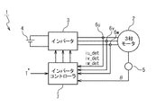
図1は、本発明の一実施形態のモータ駆動機構1の構成を示すブロック図である。モータ駆動機構1は、3相の3相モータ2と、インバータ3と、バッテリ4と、エンコーダ5と、電流センサ6u、6v、6wと、インバータコントローラ7とを備えている。インバータ3は、バッテリ4から供給される直流電圧から3相の駆動電圧を生成し、生成した駆動電流を3相モータ2に供給する。エンコーダ5は、3相モータ2のロータ位置θを逐次に検出する。電流センサ6u、6v、6wは、それぞれ、3相モータ2に供給されるu相電流、v相電流、w相電流を検出する。ここで、電流センサ6u、6v、6wが検出したu相電流、v相電流、w相電流の電流値を、それぞれ、検出電流値iu_det、iv_det、iw_detと記載する。インバータコントローラ7は、エンコーダ5によって検出されたロータ位置θと、電流センサ6u、6v、6wから出力された検出電流値iu_det、iv_det、iw_detと、外部から与えられたトルク指令T*とに応答して、インバータ3を制御する。
FIG. 1 is a block diagram showing a configuration of a motor drive mechanism 1 according to an embodiment of the present invention. The motor drive mechanism 1 includes a three-phase three-
このような構成のモータ駆動機構1は、例えば、電気自動車やハイブリッドカーのようなモータ駆動車両の駆動輪を駆動する駆動系に用いられる。この場合、3相モータ2が発生する駆動力が駆動輪に伝達される。モータ駆動車両の駆動輪を駆動するモータ駆動機構においては、電流センサのオフセット誤差は、停車時の微小振動という現象になって現れ、これがモータ駆動車両の運転者には不快に感じられることは上述の通りである。
The motor drive mechanism 1 having such a configuration is used in a drive system that drives drive wheels of a motor-driven vehicle such as an electric vehicle or a hybrid car. In this case, the driving force generated by the three-
本実施形態のモータ駆動機構1では、電流センサ6u、6v、6wのオフセット誤差の問題を解決するために、回転数に応じてu相電流、v相電流、w相電流の電流値に不感帯が設定するという手法が採用されている。即ち、3相モータ2の回転数が低速であると判断される場合にはu相電流、v相電流、w相電流の電流値に不感帯が設定される。一方、3相モータ2の回転数が高速であると判断された場合には不感帯は無効にされる。以下では、このような手法の有効性について議論する。
In the motor drive mechanism 1 of the present embodiment, in order to solve the problem of the offset error of the
不感帯を導入することは、電流センサ6u、6v、6wのオフセット誤差に起因するu相電流、v相電流、w相電流のアンバランスを解消するために有効である。上述のように、電流センサ6u、6v、6wのオフセット誤差は、u相電流、v相電流、w相電流のアンバランスを生じさせ、3相モータ2における微小振動の発生を引き起こす。不感帯を導入することにより、オフセット誤差に起因するu相電流、v相電流、w相電流のアンバランスを解消し、このような微小振動の発生を防ぐことができる。
Introducing the dead zone is effective for eliminating the imbalance between the u-phase current, the v-phase current, and the w-phase current due to the offset error of the
その一方で、不感帯を導入すると、電流センサ6u、6v、6wの入出力特性に非線形が生じ、電流波形の歪みやゼロトルクのずれという問題が発生する。電流波形の歪みは、例えば、高調波の発生による振動の発生という問題を生じさせ得る。また、ゼロトルクのずれは、無駄な電力の消費を招いて燃費低下の問題を生じさせ得る。
On the other hand, when the dead zone is introduced, nonlinearity occurs in the input / output characteristics of the
ここで、発明者の一つの知見は、電流センサ6u、6v、6wのオフセット誤差に起因する微小振動の問題は、3相モータ2が低速で運転される場合にのみ顕著に表れる一方で、高速で運転される場合には重大な問題にならないということである。即ち、電流センサ6u、6v、6wのオフセット誤差に起因する微小振動の振動周波数は、3相モータ2の回転数に比例する。従って、3相モータ2が高速で運転される場合においては、3相モータ2のロータのイナーシャ(慣性)の存在によって微小振動の影響は小さくなり、微小振動は、高速時には問題にならない。このような知見の下、本実施形態のモータ駆動機構1では、3相モータ2の回転数が低速であると判断される場合に不感帯が設定され、高速であると判断された場合には該不感帯は無効にされる。これにより、不感帯の導入による不利益を抑えながら、電流センサ6u、6v、6wのオフセット誤差に起因する微小振動の問題を解消することができる。
Here, one finding of the inventor is that the problem of minute vibration caused by the offset error of the
以下、本実施形態のモータ駆動機構1の動作について、詳細に説明する。インバータコントローラ7は、エンコーダ5によって逐次に検出された3相モータ2のロータ位置θから、3相モータ2の回転速度ωの実測値を算出する。回転速度ωの実測値が所定値よりも小さい場合、インバータコントローラ7は、回転速度ωが低速であると判断し、低速モードで動作する。そうでない場合、インバータコントローラ7は、回転速度ωが高速であると判断し、高速モードで動作する。
Hereinafter, the operation of the motor drive mechanism 1 of the present embodiment will be described in detail. The inverter controller 7 calculates an actual measurement value of the rotational speed ω of the three-
高速モード(即ち、回転速度ωが高速であると判断された場合)では、インバータコントローラ7は、電流センサ6u、6v、6wによって検知された検出電流値iu_det、iv_det、iw_detを、そのまま用いてインバータ3を制御する。詳細には、インバータコントローラ7において電流制御に実際に用いられるu相電流の電流値、v相電流の電流値、w相電流の電流値をそれぞれ、電流値iu_fb、iv_fb、iw_fbとしたとき、電流値iu_fb、iv_fb、iw_fbは、それぞれ、検出電流値iu_det、iv_det、iw_detに一致する。インバータコントローラ7は、電流値iu_fb、iv_fb、iw_fbに応答してインバータ3を制御する。
In the high speed mode (that is, when it is determined that the rotational speed ω is high), the inverter controller 7 uses the detected current values iu_det, iv_det, iw_det detected by the
一方、低速モード(即ち、回転速度ωが低速であると判断された場合)では、u相電流、v相電流、w相電流の電流値に不感帯が設定される。詳細には、図2に図示されているように、u相の検出電流値iu_detが0を含む所定区間にある場合、具体的には、−i2よりも大きく+i1よりも小さい場合(i1、i2は、いずれも正の所定値)には、インバータ3の制御に実際に用いられるu相電流の電流値iu_fbが0に設定される。ここで、i1、i2は、同一値であることが好ましい。一方、検出電流値iu_detが当該所定区間の外側にある場合には、インバータ3の制御に実際に用いられるu相電流の電流値iu_fbが検出電流値iu_detと同一の値に設定される。 On the other hand, in the low speed mode (that is, when it is determined that the rotational speed ω is low), dead zones are set in the current values of the u-phase current, the v-phase current, and the w-phase current. Specifically, as shown in FIG. 2, when the u-phase detection current value iu_det is in a predetermined section including 0, specifically, when it is larger than −i2 and smaller than + i1 (i1, i2 Is a positive predetermined value), the current value iu_fb of the u-phase current actually used for controlling the inverter 3 is set to zero. Here, i1 and i2 are preferably the same value. On the other hand, when the detected current value iu_det is outside the predetermined interval, the current value iu_fb of the u-phase current actually used for controlling the inverter 3 is set to the same value as the detected current value iu_det.
v相電流、w相電流についても同様である。低速モードが設定されると、v相の検出電流値iv_detが0を含む所定区間にある場合には、インバータ3の制御に実際に用いられるv相電流の電流値iv_fbが0に設定され、検出電流値iv_detが当該所定区間の外側にある場合には、電流値iv_fbが検出電流値iv_detと同一の値に設定される。更に、w相の検出電流値iw_detが0を含む所定区間にある場合には、インバータ3の制御に実際に用いられるw相電流の電流値iw_fbが0に設定され、検出電流値iw_detが当該所定区間の外側にある場合には、w相電流の電流値iv_fbが検出電流値iu_detと同一の値に設定される。 The same applies to the v-phase current and the w-phase current. When the low-speed mode is set, the current value iv_fb of the v-phase current actually used for the control of the inverter 3 is set to 0 when the detected current value iv_det of the v-phase is in a predetermined section including 0. When the current value iv_det is outside the predetermined section, the current value iv_fb is set to the same value as the detected current value iv_det. Further, when the detected current value iw_det of the w phase is in a predetermined section including 0, the current value iw_fb of the w phase current actually used for control of the inverter 3 is set to 0, and the detected current value iw_det is set to the predetermined range. When the current is outside the interval, the current value iv_fb of the w-phase current is set to the same value as the detected current value iu_det.
ここで、u相電流、v相電流、w相電流のそれぞれについて、不感帯は同一に設定される。言い換えれば、u相電流、v相電流、w相電流のそれぞれについてi1が、同一値に設定され、u相電流、v相電流、w相電流のそれぞれについてi2が、同一値に設定される。 Here, the dead zone is set to be the same for each of the u-phase current, the v-phase current, and the w-phase current. In other words, i1 is set to the same value for each of the u-phase current, the v-phase current, and the w-phase current, and i2 is set to the same value for each of the u-phase current, the v-phase current, and the w-phase current.
インバータコントローラ7は、上記のようにして決定されたu相、v相、w相の電流値iu_fb、iv_fb、iw_fbに応答して、インバータ3から3相モータ2に供給される3相電流を制御する。
The inverter controller 7 controls the three-phase current supplied from the inverter 3 to the three-
このように、本実施形態のモータ駆動機構1は、回転速度ωが低速であると判断された場合に不感帯を設定することにより、微小振動の問題を有効に解消する。その一方で、回転速度ωが高速であると判断された場合には不感帯を無効化し、これにより、電流波形の歪み、及び、ゼロトルクのずれの問題を回避している。 Thus, the motor drive mechanism 1 of the present embodiment effectively solves the problem of minute vibrations by setting a dead zone when it is determined that the rotational speed ω is low. On the other hand, when it is determined that the rotational speed ω is high, the dead zone is invalidated, thereby avoiding the problems of current waveform distortion and zero torque deviation.
以上には本発明の実施形態が具体的に記述されているが、本発明は、上記の実施形態に限定して解釈してはならず、本発明の実施形態には様々な変更が可能である。例えば、上記のモータ駆動機構1では、3相モータ2のロータ位置θから回転速度ωの実測値を算出し、その回転速度ωが所定値より小さい場合に3相モータ2の回転数が低速であると判断しているが、3相モータ2の回転数の判断については、様々な手法が採用され得る。例えば、インバータコントローラ7が、3相モータ2の回転速度を指示する速度指令値ω*が生成されるような制御系として構成される場合、速度指令値を用いて3相モータ2の回転数を判断してもよい。例えば、速度指令値ω*が所定値よりも小さい場合に3相モータ2の回転数が低速であると判断し、そうでない場合に3相モータ2の回転数が高速であると判断してもよい。更に、回転速度ωの実測値と速度指令値ω*の両方を用いて3相モータ2の回転数を判断してもよい。
Although the embodiments of the present invention have been specifically described above, the present invention should not be construed as being limited to the above-described embodiments, and various modifications can be made to the embodiments of the present invention. is there. For example, in the motor drive mechanism 1 described above, an actual measurement value of the rotational speed ω is calculated from the rotor position θ of the three-
また、上記の実施形態では、モータ駆動機構1が3相モータ2を備えるとして説明がなされているが、3相モータ以外の多相モータ(例えば、5相モータ)が使用されることも可能である。この場合にも、各相の電流を測定する電流センサの出力に対して回転数が低速であると判断された場合に不感帯を設定することにより、微小振動の問題を有効に解消することができる。
In the above embodiment, the motor drive mechanism 1 is described as including the three-
1:モータ駆動機構
2:3相モータ
3:インバータ
4:バッテリ
5:エンコーダ
6u、6v、6w:電流センサ
7:インバータコントローラ
1: Motor drive mechanism 2: Three-phase motor 3: Inverter 4: Battery 5: Encoder 6u, 6v, 6w: Current sensor 7: Inverter controller
Claims (5)
前記多相モータに多相電流を供給するインバータと、
前記多相モータに供給される多相電流を検出する電流検出手段と、
前記多相電流に応答して前記インバータを制御するインバータコントローラ
とを備え、
前記インバータコントローラは、前記多相モータの実際の速度に応答して第1電流制御と第2電流制御とを選択的に行い、
前記第1電流制御では、前記電流検出手段によって得られた前記多相電流の各相の検出電流値について、前記検出電流値が0を含む所定区間内にある相の電流値が0であり、前記検出電流値が0を含む所定区間内にない相の電流値が前記検出電流値に一致するとして前記多相電流が制御され、
前記第2電流制御では、前記電流検出手段によって得られた前記多相電流の検出電流値をそのまま用いて前記多相電流が制御され、
前記多相モータの実際の速度が所定値より小さい場合に前記第1電流制御が行われ、
前記多相モータの実際の速度が所定値より大きい場合に前記第2電流制御が行われる
モータ駆動機構。 A multiphase motor,
An inverter for supplying a multiphase current to the multiphase motor;
Current detection means for detecting a multiphase current supplied to the multiphase motor;
An inverter controller that controls the inverter in response to the multiphase current;
The inverter controller selectively performs a first current control and a second current control in response to an actual speed of the multiphase motor;
In the first current control, with respect to the detected current value of each phase of the multiphase current obtained by the current detecting means, the current value of the phase in the predetermined section including the detected current value of 0 is 0, The multi-phase current is controlled such that a current value of a phase that is not within a predetermined section including the detected current value is equal to the detected current value,
In the second current control, the multiphase current is controlled using the detection current value of the multiphase current obtained by the current detection unit as it is ,
The first current control is performed when the actual speed of the multiphase motor is smaller than a predetermined value,
A motor drive mechanism in which the second current control is performed when an actual speed of the multiphase motor is larger than a predetermined value .
前記多相モータに多相電流を供給するインバータと、
前記多相モータに供給される多相電流を検出する電流検出手段と、
前記多相電流に応答して前記インバータを制御するインバータコントローラ
とを備え、
前記インバータコントローラは、前記多相モータの速度指令値に応答して第1電流制御と第2電流制御とを選択的に行い、
前記第1電流制御では、前記電流検出手段によって得られた前記多相電流の各相の検出電流値について、前記検出電流値が0を含む所定区間内にある相の電流値が0であり、前記検出電流値が0を含む所定区間内にない相の電流値が前記検出電流値に一致するとして前記多相電流が制御され、
前記第2電流制御では、前記電流検出手段によって得られた前記多相電流の検出電流値をそのまま用いて前記多相電流が制御され、
前記速度指令値が所定値より小さい場合に前記第1電流制御が行われ、
前記速度指令値が所定値より大きい場合に前記第2電流制御が行われる
モータ駆動機構。 A multiphase motor,
An inverter for supplying a multiphase current to the multiphase motor;
Current detection means for detecting a multiphase current supplied to the multiphase motor;
Inverter controller for controlling the inverter in response to the multiphase current
And
The inverter controller selectively performs first current control and second current control in response to a speed command value of the multiphase motor;
In the first current control, with respect to the detected current value of each phase of the multiphase current obtained by the current detecting means, the current value of the phase in the predetermined section including the detected current value of 0 is 0, The multi-phase current is controlled such that a current value of a phase that is not within a predetermined section including the detected current value is equal to the detected current value,
In the second current control, the multiphase current is controlled using the detection current value of the multiphase current obtained by the current detection unit as it is,
The first current control is performed when the speed command value is smaller than a predetermined value,
A motor drive mechanism in which the second current control is performed when the speed command value is greater than a predetermined value.
電流検出手段によって検出された前記多相電流に応答して前記インバータを制御する制御手段
を備え、
前記制御手段は、前記多相モータの実際の速度に応答して第1電流制御と第2電流制御とを選択的に行い、
前記第1電流制御では、前記電流検出手段によって得られた前記多相電流の各相の検出電流値について、前記検出電流値が0を含む所定区間内にある相の電流値が0であり、前記検出電流値が0を含む所定区間内にない相の電流値が前記検出電流値に一致するとして前記多相電流が制御され、
前記第2電流制御では、前記電流検出手段によって得られた前記多相電流の検出電流値をそのまま用いて前記多相電流が制御され、
前記多相モータの実際の速度が所定値より小さい場合に前記第1電流制御が行われ、
前記多相モータの実際の速度が所定値より大きい場合に前記第2電流制御が行われる
モータ制御装置。 A motor control device for controlling an inverter that supplies a polyphase current to a polyphase motor,
Control means for controlling the inverter in response to the multiphase current detected by the current detection means;
The control means selectively performs first current control and second current control in response to an actual speed of the multiphase motor,
In the first current control, with respect to the detected current value of each phase of the multiphase current obtained by the current detecting means, the current value of the phase in the predetermined section including the detected current value of 0 is 0, The multi-phase current is controlled such that a current value of a phase that is not within a predetermined section including the detected current value is equal to the detected current value,
In the second current control, the multiphase current is controlled using the detection current value of the multiphase current obtained by the current detection unit as it is ,
The first current control is performed when the actual speed of the multiphase motor is smaller than a predetermined value,
The motor control device in which the second current control is performed when an actual speed of the multiphase motor is larger than a predetermined value .
電流検出手段によって検出された前記多相電流に応答して前記インバータを制御する制御手段Control means for controlling the inverter in response to the multiphase current detected by the current detection means
を備え、With
前記制御手段は、前記多相モータの速度指令値に応答して第1電流制御と第2電流制御とを選択的に行い、The control means selectively performs first current control and second current control in response to a speed command value of the multiphase motor,
前記第1電流制御では、前記電流検出手段によって得られた前記多相電流の各相の検出電流値について、前記検出電流値が0を含む所定区間内にある相の電流値が0であり、前記検出電流値が0を含む所定区間内にない相の電流値が前記検出電流値に一致するとして前記多相電流が制御され、In the first current control, with respect to the detected current value of each phase of the multiphase current obtained by the current detecting means, the current value of the phase in the predetermined section including the detected current value of 0 is 0, The multi-phase current is controlled such that a current value of a phase that is not within a predetermined section including the detected current value is equal to the detected current value,
前記第2電流制御では、前記電流検出手段によって得られた前記多相電流の検出電流値をそのまま用いて前記多相電流が制御され、In the second current control, the multiphase current is controlled using the detection current value of the multiphase current obtained by the current detection unit as it is,
前記速度指令値が所定値より小さい場合に前記第1電流制御が行われ、The first current control is performed when the speed command value is smaller than a predetermined value,
前記速度指令値が所定値より大きい場合に前記第2電流制御が行われるThe second current control is performed when the speed command value is larger than a predetermined value.
モータ制御装置。Motor control device.
駆動輪
とを具備し、
前記駆動輪がモータ駆動機構によって駆動される
モータ駆動車両。 The motor drive mechanism according to claim 1 or 2 ,
Drive wheels,
A motor-driven vehicle in which the drive wheels are driven by a motor drive mechanism.
Priority Applications (1)
| Application Number | Priority Date | Filing Date | Title |
|---|---|---|---|
| JP2010104949A JP5590959B2 (en) | 2010-04-30 | 2010-04-30 | Motor drive mechanism, motor control device, and motor drive vehicle |
Applications Claiming Priority (1)
| Application Number | Priority Date | Filing Date | Title |
|---|---|---|---|
| JP2010104949A JP5590959B2 (en) | 2010-04-30 | 2010-04-30 | Motor drive mechanism, motor control device, and motor drive vehicle |
Publications (2)
| Publication Number | Publication Date |
|---|---|
| JP2011234585A JP2011234585A (en) | 2011-11-17 |
| JP5590959B2 true JP5590959B2 (en) | 2014-09-17 |
Family
ID=45323296
Family Applications (1)
| Application Number | Title | Priority Date | Filing Date |
|---|---|---|---|
| JP2010104949A Expired - Fee Related JP5590959B2 (en) | 2010-04-30 | 2010-04-30 | Motor drive mechanism, motor control device, and motor drive vehicle |
Country Status (1)
| Country | Link |
|---|---|
| JP (1) | JP5590959B2 (en) |
Family Cites Families (3)
| Publication number | Priority date | Publication date | Assignee | Title |
|---|---|---|---|---|
| JP3830737B2 (en) * | 2000-07-17 | 2006-10-11 | 三菱電機株式会社 | Electric power steering control device |
| JP2003081110A (en) * | 2001-09-12 | 2003-03-19 | Hitachi Unisia Automotive Ltd | Control device for electric power steering device |
| JP4561318B2 (en) * | 2004-11-05 | 2010-10-13 | 日本精工株式会社 | Electric power steering device |
-
2010
- 2010-04-30 JP JP2010104949A patent/JP5590959B2/en not_active Expired - Fee Related
Also Published As
| Publication number | Publication date |
|---|---|
| JP2011234585A (en) | 2011-11-17 |
Similar Documents
| Publication | Publication Date | Title |
|---|---|---|
| US10266198B2 (en) | Motor control device | |
| JP3701207B2 (en) | Motor control device and electric vehicle using the same | |
| WO2010001579A1 (en) | Motor control device and vehicle-steering device comprising same | |
| US20110043144A1 (en) | Motor controller and electric power steering system | |
| WO2009123113A1 (en) | Motor control device and electric power steering device | |
| JP6445937B2 (en) | Electric power steering device | |
| WO2009123107A1 (en) | Motor control device and electric power steering device | |
| JP3674919B2 (en) | Electric power steering apparatus and control method thereof | |
| JP2010057228A (en) | Motor controller | |
| JP4918870B2 (en) | Motor control device and electric power steering device | |
| JP2014135866A (en) | Motor controller and electrically-driven power steering device | |
| JP2007228700A (en) | Motor control device | |
| JP5376213B2 (en) | Motor control device | |
| JP4628833B2 (en) | Electric power steering device | |
| JP2010200430A (en) | Drive controller for motors | |
| JP5136839B2 (en) | Motor control device | |
| US10946890B2 (en) | Steering control unit | |
| JP2012147531A (en) | Electric power steering apparatus | |
| JP2008154308A (en) | Controller of motor-driven power steering system | |
| JP2011244571A (en) | Motor drive mechanism and motor control apparatus | |
| JP5590959B2 (en) | Motor drive mechanism, motor control device, and motor drive vehicle | |
| JP5028813B2 (en) | Electric power steering apparatus and control apparatus therefor | |
| US11502632B2 (en) | Motor control device and electric vehicle | |
| JP5176369B2 (en) | Electric power steering device | |
| JP2004023920A (en) | Ac motor controller |
Legal Events
| Date | Code | Title | Description |
|---|---|---|---|
| A621 | Written request for application examination |
Free format text: JAPANESE INTERMEDIATE CODE: A621 Effective date: 20121024 |
|
| A977 | Report on retrieval |
Free format text: JAPANESE INTERMEDIATE CODE: A971007 Effective date: 20131120 |
|
| A131 | Notification of reasons for refusal |
Free format text: JAPANESE INTERMEDIATE CODE: A131 Effective date: 20131125 |
|
| A521 | Request for written amendment filed |
Free format text: JAPANESE INTERMEDIATE CODE: A523 Effective date: 20140123 |
|
| TRDD | Decision of grant or rejection written | ||
| A01 | Written decision to grant a patent or to grant a registration (utility model) |
Free format text: JAPANESE INTERMEDIATE CODE: A01 Effective date: 20140702 |
|
| A61 | First payment of annual fees (during grant procedure) |
Free format text: JAPANESE INTERMEDIATE CODE: A61 Effective date: 20140729 |
|
| R151 | Written notification of patent or utility model registration |
Ref document number: 5590959 Country of ref document: JP Free format text: JAPANESE INTERMEDIATE CODE: R151 |
|
| R250 | Receipt of annual fees |
Free format text: JAPANESE INTERMEDIATE CODE: R250 |
|
| LAPS | Cancellation because of no payment of annual fees |