JP5587852B2 - Image processing apparatus and image processing method - Google Patents
Image processing apparatus and image processing method Download PDFInfo
- Publication number
- JP5587852B2 JP5587852B2 JP2011247749A JP2011247749A JP5587852B2 JP 5587852 B2 JP5587852 B2 JP 5587852B2 JP 2011247749 A JP2011247749 A JP 2011247749A JP 2011247749 A JP2011247749 A JP 2011247749A JP 5587852 B2 JP5587852 B2 JP 5587852B2
- Authority
- JP
- Japan
- Prior art keywords
- image
- region
- background
- area
- vehicle
- Prior art date
- Legal status (The legal status is an assumption and is not a legal conclusion. Google has not performed a legal analysis and makes no representation as to the accuracy of the status listed.)
- Active
Links
Images


Classifications
-
- H—ELECTRICITY
- H04—ELECTRIC COMMUNICATION TECHNIQUE
- H04N—PICTORIAL COMMUNICATION, e.g. TELEVISION
- H04N13/00—Stereoscopic video systems; Multi-view video systems; Details thereof
- H04N13/20—Image signal generators
- H04N13/204—Image signal generators using stereoscopic image cameras
- H04N13/246—Calibration of cameras
-
- G—PHYSICS
- G01—MEASURING; TESTING
- G01C—MEASURING DISTANCES, LEVELS OR BEARINGS; SURVEYING; NAVIGATION; GYROSCOPIC INSTRUMENTS; PHOTOGRAMMETRY OR VIDEOGRAMMETRY
- G01C3/00—Measuring distances in line of sight; Optical rangefinders
- G01C3/10—Measuring distances in line of sight; Optical rangefinders using a parallactic triangle with variable angles and a base of fixed length in the observation station, e.g. in the instrument
- G01C3/14—Measuring distances in line of sight; Optical rangefinders using a parallactic triangle with variable angles and a base of fixed length in the observation station, e.g. in the instrument with binocular observation at a single point, e.g. stereoscopic type
-
- G—PHYSICS
- G06—COMPUTING; CALCULATING OR COUNTING
- G06T—IMAGE DATA PROCESSING OR GENERATION, IN GENERAL
- G06T7/00—Image analysis
- G06T7/50—Depth or shape recovery
- G06T7/55—Depth or shape recovery from multiple images
- G06T7/593—Depth or shape recovery from multiple images from stereo images
-
- G—PHYSICS
- G08—SIGNALLING
- G08G—TRAFFIC CONTROL SYSTEMS
- G08G1/00—Traffic control systems for road vehicles
- G08G1/16—Anti-collision systems
- G08G1/166—Anti-collision systems for active traffic, e.g. moving vehicles, pedestrians, bikes
-
- G—PHYSICS
- G08—SIGNALLING
- G08G—TRAFFIC CONTROL SYSTEMS
- G08G1/00—Traffic control systems for road vehicles
- G08G1/16—Anti-collision systems
- G08G1/167—Driving aids for lane monitoring, lane changing, e.g. blind spot detection
-
- H—ELECTRICITY
- H04—ELECTRIC COMMUNICATION TECHNIQUE
- H04N—PICTORIAL COMMUNICATION, e.g. TELEVISION
- H04N13/00—Stereoscopic video systems; Multi-view video systems; Details thereof
- H04N13/20—Image signal generators
- H04N13/204—Image signal generators using stereoscopic image cameras
- H04N13/239—Image signal generators using stereoscopic image cameras using two 2D image sensors having a relative position equal to or related to the interocular distance
-
- G—PHYSICS
- G06—COMPUTING; CALCULATING OR COUNTING
- G06T—IMAGE DATA PROCESSING OR GENERATION, IN GENERAL
- G06T2207/00—Indexing scheme for image analysis or image enhancement
- G06T2207/10—Image acquisition modality
- G06T2207/10004—Still image; Photographic image
- G06T2207/10012—Stereo images
-
- G—PHYSICS
- G06—COMPUTING; CALCULATING OR COUNTING
- G06T—IMAGE DATA PROCESSING OR GENERATION, IN GENERAL
- G06T2207/00—Indexing scheme for image analysis or image enhancement
- G06T2207/30—Subject of image; Context of image processing
- G06T2207/30248—Vehicle exterior or interior
- G06T2207/30252—Vehicle exterior; Vicinity of vehicle
- G06T2207/30261—Obstacle
-
- H—ELECTRICITY
- H04—ELECTRIC COMMUNICATION TECHNIQUE
- H04N—PICTORIAL COMMUNICATION, e.g. TELEVISION
- H04N13/00—Stereoscopic video systems; Multi-view video systems; Details thereof
- H04N2013/0074—Stereoscopic image analysis
- H04N2013/0085—Motion estimation from stereoscopic image signals
Description
本発明は、複数の撮像素子で撮像した画像を画像処理する画像処理装置及び画像処理方法に関する。 The present invention relates to an image processing apparatus and an image processing method that perform image processing on images captured by a plurality of image sensors.
近年、ステレオカメラ装置など複数のカメラを用いて歩行者や車両などの障害物を検出する障害物検出装置が実用化されている。ステレオカメラ装置とは、同時刻に撮像された複数の画像上における同一対象物の位置ずれ(視差)を算出し、その視差をもとに対象物の実空間上の位置を周知の変換式により算出し、対象物の認識を行う画像処理装置である。ステレオカメラ装置は、不審者の侵入や異常を検知する監視システムや車の安全走行を支援する車載システムなどに適用することができる(特許文献1参照)。 In recent years, an obstacle detection apparatus that detects an obstacle such as a pedestrian or a vehicle using a plurality of cameras such as a stereo camera apparatus has been put into practical use. The stereo camera device calculates the positional deviation (parallax) of the same object on a plurality of images taken at the same time, and based on the parallax, the position of the object in real space is calculated by a known conversion formula. An image processing apparatus that calculates and recognizes an object. The stereo camera device can be applied to a monitoring system that detects intrusion or abnormality of a suspicious person, an in-vehicle system that supports safe driving of a vehicle, and the like (see Patent Document 1).
撮像画像上の対象物は、カメラとの距離が長くなるに応じてその大きさが小さくなり、画像が粗くなる。したがって、ステレオカメラ装置は、対象物との距離が長くなるに応じて、対象物とその周囲の背景との区別が困難になり、視差の誤差が多くなるという問題を有している。 The object on the captured image becomes smaller in size as the distance from the camera becomes longer, and the image becomes rougher. Therefore, the stereo camera device has a problem that as the distance from the object increases, it becomes difficult to distinguish the object from the surrounding background, and the error in parallax increases.
本発明は、上記の点に鑑みてなされたものであり、その目的とするところは、対象物体までの距離を測定する際に、距離精度を向上させ、従来より遠い距離の対象物でも正確な距離を測定することができる画像処理装置及び画像処理方法を提供することである。 The present invention has been made in view of the above points. The object of the present invention is to improve the distance accuracy when measuring the distance to the target object, and to accurately correct an object at a distance farther than before. An object of the present invention is to provide an image processing apparatus and an image processing method capable of measuring a distance.
上記課題を解決する本発明の画像処理装置及び画像処理方法は、一対の撮像素子で同時刻に同方向を撮像した一対の画像の一方の画像から対象物の画像を含む一方画像対象物領域を抽出する。そして、一方画像対象物領域を構成する複数の画像構成部分についてそれぞれ対象物画像構成部分と背景画像構成部分のいずれであるかの確度である背景度を算出する。そして、背景度を用いて他方の画像内から一方画像対象物領域と類似した画像を有する他方画像対象物領域を抽出して、一方画像対象物領域と前記他方画像対象物領域との視差を算出する。 An image processing apparatus and an image processing method according to the present invention for solving the above-described problems include an image object region including an image of an object from one image of a pair of images captured in the same direction at the same time by a pair of imaging elements. Extract. On the other hand, the degree of background, which is the accuracy of the object image constituent part or the background image constituent part, is calculated for each of the plurality of image constituent parts constituting the image object region. Then, the other image object area having an image similar to the one image object area is extracted from the other image using the background level, and the parallax between the one image object area and the other image object area is calculated. To do.
本発明によれば、他方の画像内から一方画像対象物領域と類似した他方画像対象物領域を抽出する際に、背景度により重み付けをしているので、背景の影響をより少なくすることができる。したがって、対象物の正確な視差情報を得ることができ、対象物までの距離精度を向上させることができる。したがって、従来よりも遠い距離の対象物でも正確な距離を測定できる。なお、上記した以外の課題、構成及び効果は、以下の実施形態の説明により明らかにされる。 According to the present invention, when the other image object region similar to the one image object region is extracted from the other image, weighting is performed based on the background degree, so that the influence of the background can be further reduced. . Therefore, accurate parallax information of the object can be obtained, and the distance accuracy to the object can be improved. Therefore, it is possible to measure an accurate distance even with an object that is farther than before. Problems, configurations, and effects other than those described above will be clarified by the following description of the embodiments.
次に、本実施の形態について以下に図面を用いて説明する。
本実施の形態では、本発明を自車両に搭載されたステレオカメラ装置の映像を用いて先行車両を検出するシステムに適用した場合について説明する。
Next, the present embodiment will be described below with reference to the drawings.
In the present embodiment, a case will be described in which the present invention is applied to a system that detects a preceding vehicle using an image of a stereo camera device mounted on the host vehicle.
まず、図1を用いて本システムの概要について説明する。図1において、104は車両103に搭載されたステレオカメラ装置である。ステレオカメラ装置104は、画像処理により車両(自車両)103の前方を走行する先行車両102の存在を検出し、車両103から先行車両102までの相対距離、相対速度を算出する。
First, the outline of this system will be described with reference to FIG. In FIG. 1,
ステレオカメラ装置104は、車両103の前方を撮像する一対の撮像手段として左撮像部(左カメラ)105と右撮像部(右カメラ)106を備えており、左撮像部105からの映像が左画像入力部107に入力され、右撮像部106からの映像が右画像入力部108に入力される。左撮像部105と右撮像部106は、CCDなどの撮像素子をそれぞれ有しており、互いに車幅方向に離間した位置から車両前方を撮像するように車両103に設置されている。
The
車両検出部109は、左画像入力部107に入力された左画像301(図3参照)内を探索して、先行車両102が撮像されている画像領域を左画像車両領域(一方画像対象物領域)302として抽出する(一方画像対象物領域抽出手段)。右画像類似領域抽出部110は、右画像入力部108に入力された右画像501(図5参照)内を探索して、車両検出部109で抽出した左画像車両領域302と類似した画像領域を右画像類似領域(他方画像類似領域)503(図5参照)として抽出する(他方画像類似領域抽出手段)。
The
背景度算出部111は、図3に示すように左画像車両領域302を構成する複数の画像構成部分として例えば各画素について、それぞれ先行車両102の画像を構成する車両画像構成部分304と先行車両102以外の背景の画像を構成する背景画像構成部分303のいずれであるかの確度である背景度を算出する。なお、背景度を算出する範囲は画素単位に限定されるものではなく、例えば、複数の画素を一つの範囲として、その背景度を算出してもよい。
As shown in FIG. 3, the background degree calculation unit 111 includes a vehicle
視差算出部112は、図5に示すように右画像501内の右画像類似領域503の周辺範囲を探索して、左画像車両領域302に最も類似する画像領域を右画像車両領域として抽出する。視差算出部112は、背景度を用いた重み付けをして探索を行う。そして、抽出した右画像車両領域と左画像車両領域302との視差を算出する。
As shown in FIG. 5, the
相対距離・相対速度算出部113では、視差算出部112で算出した先行車両102の視差から、先行車両102と車両103との相対距離、相対速度を算出する。車両103は、相対距離・相対速度算出部113で算出した先行車両102との相対距離・相対速度の値に基づき、アクセルやブレーキを制御して、例えば先行車両102に追従する制御や、先行車両102への追突を防止する制御などの走行制御を行う。
The relative distance / relative
次に、図2と図3を用いて車両検出部109で行う処理について説明する。図2は、車両検出部109で行われる処理内容を説明するフローチャート、図3は、左画像車両領域出力処理207の出力内容を説明する図である。
Next, processing performed by the
まず、左画像取得処理201では、左撮像部105で右撮像部106と同時刻に撮像された左画像301の取得が行われる。左画像301は、左撮像部105からステレオカメラ装置104の左画像入力部107に入力される。そして、処理領域決定処理202では、左画像301内から先行車両102が撮像されている部分を抽出する処理を行うための処理領域を決定する処理が行われる。
First, in the left
処理領域を決定する方法の1つとして、左撮像部105で撮像された左画像301内から、車両103が走行する道路101の車線(走行レーン)の両側の2本の車線境界線115を検出し、その検出した2本の車線境界線115に挟まれる領域を、処理領域として決定する方法を例として挙げることができる。
As one method of determining the processing area, two
次に、縦エッジペア抽出処理203では、処理領域決定処理202で決定した処理領域内において画像301の縦(v)方向に画像輝度のエッジ成分がペアとなって存在する縦エッジのペアを抽出する処理が行われる。縦エッジを抽出するには、画像301を横(u)方向に探索し、画像301の輝度値の勾配が一定閾値以上の部分が、画像301の縦方向に連続して存在する部分を検出する。
Next, in the vertical edge
次に、パターンマッチ処理204において、縦エッジペア抽出処理204で抽出した2つの縦エッジで囲まれる矩形の領域に対して、車両学習データ205との輝度パターンの類似性を計算し、縦エッジペアで囲まれる矩形領域が、先行車両102を後方から撮像した部分であるか否かを判定する。類似性の判定には、ニューラルネットワークやサポートベクターマシンといった手法を使う。また、車両学習データ205は、予め様々な車両を後方から撮像した多数のポジティブデータ画像と、車両ではない被写体を撮像した多数のネガティブデータ画像を準備しておくものとする。
Next, in the
次に、車両領域抽出処理206にて、パターンマッチ処理204で先行車両102を後方から撮像した画像であると判定された画像領域を左画像車両領域302として抽出し、車両領域出力処理207にて、左画像車両領域302の矩形の4頂点P1〜P4の座標値P1(u1,v1)、P2(u1,v2)、P3(u2,v1)、P4(u2,v2)を出力する。
Next, in the vehicle
ここで抽出した左画像車両領域302は、図3に示すように、矩形の画像領域内に、先行車両102を撮像した対象物画像構成部分(図3にて先行車両102の輪郭で囲まれる画像構成部分)304と、先行車両102ではない背景画像構成部分(図3にて画像領域302の外枠と先行車両102の輪郭との間で囲まれるハッチング部分)303の両方を含んでいる。
As shown in FIG. 3, the extracted left
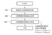
次に、図4及び図5を用いてステレオカメラ装置104の右画像類似領域抽出部110の処理内容について詳細に説明する。図4は、右画像類似領域抽出部110で行われる処理内容を説明するフローチャート、図5は、右画像類似領域抽出処理の内容を説明する図である。
Next, the processing contents of the right image similar
まず、左画像・右画像取得処理401にて、車両検出部109で左画像301から抽出された左画像車両領域302と、右撮像部106で左画像301と同時刻に撮像された右画像501とを取得する。そして、右画像類似領域抽出処理402において、左画像車両領域302内に撮像されている先行車両102と同じ先行車両102が右画像501に撮像されている画像領域を、左画像車両領域302に類似する右画像類似領域503として右画像501から抽出する。
First, in the left image / right
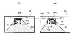
図5に、左画像車両領域302に類似する右画像類似領域503を右画像501から抽出する方法を示す。ここで、ステレオカメラ装置104の左撮像部105と右撮像部106は出荷時のキャリブレーションによって平行化されていることを前提とする。平行化とは、左右撮像部105、106の光軸が平行であることを意味する。
FIG. 5 shows a method for extracting a right image
ここでは、左画像車両領域302と同じ大きさを有する矩形の探索領域502を用いて、右画像501内を探索し、左画像車両領域302と最も類似する探索領域502を右画像類似領域503として抽出する処理が行われる。
Here, a
具体的には、左画像車両領域302の矩形の4頂点の座標値がP1(u1,v1)、P2(u1,v2)、P3(u2,v1)、P4(u2,v2)であるとき、右画像501内の (0,v1)、(0,v2)、(u2-u1,v1)、(u2-u1,v2)を4頂点とする探索領域502を、右画像501において水平に1画素ずつ、あるいは複数画素ずつ移動させて探索する。そして、探索する際に、左画像車両領域302内の各画素の輝度値と、探索領域502内の各画素の輝度値との差分値をそれぞれ計算する。すなわち、左画像車両領域302と探索領域502の同じ画素位置における輝度の差分値を、各画素についてそれぞれ計算する。
Specifically, the coordinate values of the four vertices of the rectangle of the left
そして、各差分値を総和した領域内総和値が最も小さくなる位置の探索領域502を、左画像車両領域302に類似する右画像類似領域503として抽出する。ここで、ステレオカメラ装置104の左撮像部105と右撮像部106は出荷時のキャリブレーションによって、同じ感度特性を持つものとする。
Then, the
次に、右画像類似領域出力処理403において、右画像類似領域抽出処理402で抽出した右画像類似領域503の矩形の4頂点P11〜P14の座標値P11(u3,v1)、P12(u3,v2)、P13(u4,v1)、P14(u4,v2)を出力する。
Next, in the right image similar
次に、図6を用いてステレオカメラ装置104の背景度算出部111で行う処理について説明する。図6は、背景度算出部111で行われる処理フローである。
Next, processing performed by the background degree calculation unit 111 of the
まず、左右画像車両領域取得処理601では、車両検出部109から出力された左画像車両領域302と、右画像類似領域抽出部110から出力された右画像類似領域503を取得する。次に,左画像車両領域302の各画素が対象物画像構成部分と背景画像構成部分のいずれであるのかの確度である背景度を算出する処理が行われる。背景度は、第1の背景度算出処理602により第1の背景度が算出され、第2の背景度算出処理603により第2の背景度が算出され、最終背景度算出処理604により、第1の背景度と第2の背景度を総合した最終的な背景度が算出される。
First, in the left and right image vehicle
まず、第1の背景度算出処理602では、車両知識により背景度を算出する処理が行われる。ここでは、左画像車両領域302の各画素が対象物画像構成部分と背景画像構成部分のいずれであるのかの確度を事前に規定した車両知識を用いて背景度を算出する。背景度は、ある画素が背景となる確度を表した値であり、例えば背景度1のときはその画素は背景画像構成部分と判断でき、背景度0のときはその画素が対象物画像構成部分と判断できる。そして、背景度が0と1の中間のときはその値に比例した確度となる。図7に車両知識を用いた背景度の算出例を示す。ここでは,矩形で示した中心領域701内は車両の領域(背景度0)であり,左画像車両領域302の外枠端は背景である(背景度1)という車両知識を用いて、線形的に背景度を補完することにより各画素の背景度を算出する。
First, in the first background
次に、第2の背景度算出処理603では、重ね合わせ誤差により背景度を算出する処理が行われる。ここでは、左画像車両領域302と右画像類似領域503とを重ね合わせた際の輝度値の誤差の大小より各画素の背景度が算出される。図8に重ね合わせ誤差により各画素の背景度を算出する方法を示す。
Next, in the second background
まず、左画像車両領域302と右画像類似領域503の座標起点が一致するように重ね合わせる。そして、左画像車両領域302と右画像類似領域503の同じ画素位置における輝度の差分値、および領域内の差分の平均Dと標準偏差σを計算する。そして、差分値がD±1σよりも小さいときは背景度0、差分値がD±1σ以上D±3σ以下のときは背景度0.5、差分値がD±3σよりも大きいときは背景度1.0として、各画素についてそれぞれ背景度を算出する。
First, the left
次に、最終背景度算出処理604では、第1の背景度算出処理602において出力される背景度と,第2の背景度算出処理603において出力される背景度を、各画素毎に掛け算を行い,各画素についてそれぞれ最終的な背景度を算出する。
Next, in the final background
なお、上記では、第1の背景度と第2の背景度を用いて最終背景度を算出する場合について説明したが、この構成に限定されるものではなく、第1の背景度と第2の背景度の少なくとも一方を用いるものであればよく、また、背景度の算出方法も一例であり、他の方法によって背景度を算出してもよい。 In the above description, the case where the final background degree is calculated using the first background degree and the second background degree has been described. However, the present invention is not limited to this configuration, and the first background degree and the second background degree are calculated. Any method may be used as long as at least one of the background degrees is used. The background degree calculation method is also an example, and the background degree may be calculated by another method.
次に、図9を用いて視差算出部112の処理について説明する。図9は、視差算出部112で行われる処理内容を説明するフローチャートである。
Next, the processing of the
まず、左右画像車両領域取得処理901では、車両検出部109から出力される左画像車両領域302と、右画像類似領域抽出部110から出力される右画像類似領域503を取得する処理が行われる。
First, in the left and right image vehicle
次に、左右車両領域マッチング処理902では,背景度を用いて左画像車両領域302に最も類似する右画像車両領域(他方画像対象物領域)を右画像501から抽出する処理が行われる。ここでは、右画像501内で右画像類似領域503を中心として予め設定された大きさを有する周辺範囲内を探索する。
Next, in the left and right vehicle
そして、周辺範囲を探索する際に、左画像車両領域302内の各画素の輝度値と、探索領域502内の各画素の輝度値との差分値をそれぞれ計算する。すなわち、左画像車両領域302と探索領域502との同じ画素位置における輝度値の差分値を、各画素についてそれぞれ計算する。これにより、左画像車両領域302を右画像501に重ね合わせたときに互いに同じ位置となる画素の輝度値の差分値が各画素についてそれぞれ算出されたこととなる。
Then, when searching for the peripheral range, a difference value between the luminance value of each pixel in the left
そして、最終背景度算出処理604によって得られた各画素の背景度を用いて、各画素の輝度値の差分値に、重み付けを行う。ここでは、1から背景度を減算した値(1−背景度)に対して差分値を乗算した値(=(1−背景度)×差分値)を、各画素について算出し、探索領域502内の総和値を算出する。そして、周辺範囲を探索した中で、総和値が一番小さくなる位置の探索領域502を、右画像車両領域として抽出する。
Then, using the background level of each pixel obtained by the final background
次に、視差算出処理903では,背景度を用いた左右車両領域マッチング処理902の結果として得られる視差を出力する。ここで、左画像車両領域302の左上座標を(u1,v1),右画像においてマッチングした右画像車両領域の左上座標を(u’1,v1)とすると,u1-u’1 が視差を表し,この値が出力される。
Next, in the
視差算出部112では、左画像車両領域302に類似する右画像車両領域を抽出する際に、背景度により重み付けしているので、背景の影響をより少なくすることができる。したがって、先行車両102の正確な視差を算出することができる。
In the
また、視差算出部112では、右画像501内で右画像類似領域503を中心とした周辺範囲を探索して、その探索範囲を絞り込んでいるので、右画像501内を広く探索する場合と比較して、探索時間を短くすることができる。特に、右画像車両領域を抽出する処理において背景度により重み付けをする演算処理を行っているので、探索範囲を絞り込むことによって、演算処理の負荷を軽減し、処理速度の向上を図ることができる。
In addition, the
次に、図10を用いて、相対距離・相対速度算出部113による相対距離の算出方法について説明する。まず、図10において、左画像301と右画像501の対応点1001(左右カメラの同一物体)のカメラからの距離を算出する方法を説明する。
Next, a relative distance calculation method by the relative distance / relative
図10において、左の撮像部105は、レンズ1002と撮像面1003から成る焦点距離f、光軸1008のカメラであり、右撮像部106は、レンズ1004と撮像面1005から成る焦点距離f、光軸1009のカメラである。カメラ前方にある点1001は、左の撮像部105の撮像面1003の点1006(光軸1008からd2の距離)へ撮像され、左画像301では点1006(光軸1108からd4画素の位置)となる。同様に、カメラ前方にある点1001は、右の撮像部106の撮像面1005の点1007(光軸1009からd3の距離)に撮像され、右画像501では点1007(光軸1009からd5画素の位置)となる。
In FIG. 10, the
このように同一の物体の点1001が、左画像301では光軸1008から左へd4画素の位置、右画像501では光軸1009から右へd5の位置に撮像され、d4+d5画素の視差が発生する。このため、左の撮像部105の光軸1008と点1001との距離をxとすると、以下の式により、ステレオカメラ装置104から点1001までの距離Dを求めることができる。
In this way, the
点1001と左の撮像部105との関係から d2 : f = x : D
点1001と右の撮像部106との関係から d3 : f = (d-x) : D
From the relationship between the
From the relationship between the
従って、D = f × d / (d2 + d3) = f × d / { (d4 + d5 ) × a} となる。ここで、aは撮像面1003、1005の撮像素子のサイズである。
Therefore, D = f × d / (
上記したステレオカメラ装置104は、画像処理装置として、左画像301から視差情報を取得する対象物である先行車両102を認識し、左画像301内に先行車両102の画像を含む左画像車両領域302を抽出し、左画像対象物領域を構成する各画素について背景度を算出し、背景度を用いて右画像501内から左画像車両領域302に類似した右画像車両領域を抽出し、左画像車両領域と右画像車両領域との視差を算出する。
The
上記したステレオカメラ装置104によれば、左画像車両領域302に類似する右画像車両領域を抽出する際に、背景度により重み付けしているので、背景の影響をより少なくすることができる。したがって、先行車両102の正確な視差情報を得ることができ、先行車両102までの距離精度を向上させることができる。したがって、従来よりも遠い距離の先行車両102でも正確な距離を測定できる。
According to the
そして、上記したステレオカメラ装置104は、左画像車両領域302を用いて右画像501から右画像類似領域503を予め抽出しておき、背景度を用いて右画像501内から右画像車両領域を抽出する際に、右画像類似領域503の周辺範囲を探索して右画像車両領域を抽出してもよい。これにより、右画像501内を広く探索する場合と比較して、探索時間を短くすることができ、特に、右画像車両領域を抽出する処理において背景度により重み付けをする演算処理を行っているので、その演算処理の負荷を軽減し、処理速度の向上を図ることができる。
Then, the
なお、本発明は、上述の実施の形態の内容に限定されるものではなく、本発明の趣旨を逸脱しない範囲で種々の変更が可能である。例えば、上述の実施の形態では、右画像類似領域抽出部110で右画像類似領域503を抽出し、視差算出部112でその右画像類似領域503の周辺範囲内を探索して、右画像車両領域を抽出する場合を例に説明したが、これに限定されるものではない。例えば、右画像類似領域抽出処理402と同様に、右画像内において (0,v1)、(0,v2)、(u2-u1,v1)、(u2-u1,v2)を4頂点とする探索領域502を水平に移動させて、左画像車両領域302と類似する右画像車両領域を探索する構成としてもよい。
The present invention is not limited to the contents of the above-described embodiment, and various modifications can be made without departing from the spirit of the present invention. For example, in the above-described embodiment, the right image similar
なお、本発明の実施形態について詳述したが、本発明は、前記の実施形態に限定されるものではなく、特許請求の範囲に記載された本発明の精神を逸脱しない範囲で、種々の設計変更を行うことができるものである。例えば、前記した実施の形態は本発明を分かりやすく説明するために詳細に説明したものであり、必ずしも説明した全ての構成を備えるものに限定されるものではない。また、ある実施形態の構成の一部を他の実施形態の構成に置き換えることが可能であり、また、ある実施形態の構成に他の実施形態の構成を加えることも可能である。さらに、各実施形態の構成の一部について、他の構成の追加・削除・置換をすることが可能である。 Although the embodiments of the present invention have been described in detail, the present invention is not limited to the above-described embodiments, and various designs can be made without departing from the spirit of the present invention described in the claims. It can be changed. For example, the above-described embodiment has been described in detail for easy understanding of the present invention, and is not necessarily limited to one having all the configurations described. Further, a part of the configuration of an embodiment can be replaced with the configuration of another embodiment, and the configuration of another embodiment can be added to the configuration of an embodiment. Furthermore, it is possible to add, delete, and replace other configurations for a part of the configuration of each embodiment.
102 先行車両(対象物)
103 車両(自車両)
104 ステレオカメラ装置(画像処理装置)
105 左撮像部(左カメラ)
106 右撮像部(右カメラ)
107 左画像入力部
108 右画像入力部
109 車両検出部
110 右画像類似領域抽出部
111 背景度算出部
112 視差算出部
113 相対距離・相対速度算出部
302 左画像車両領域(一方画像対象物領域)
502 探索領域
503 右画像類似領域
102 preceding vehicle (target)
103 Vehicle (own vehicle)
104 Stereo camera device (image processing device)
105 Left imaging unit (left camera)
106 Right imaging unit (right camera)
107 Left image input section
108 Right image input section
109 Vehicle detector
110 Right image similar area extraction unit
111 Background degree calculator
112 Parallax calculator
113 Relative distance / relative speed calculator
302 Left image vehicle area (one image object area)
502 Search area
503 Right image similar area
Claims (5)
一方の画像から視差情報を取得する対象物を認識して、前記一方の画像内に該対象物の画像を含む撮像画像領域である一方画像対象物領域を抽出する一方画像対象物領域抽出手段と、
該一方画像対象物領域を構成する複数の画像構成部分について、それぞれ前記対象物の画像を構成する対象物画像構成部分と前記対象物以外の背景の画像を構成する背景画像構成部分のいずれであるかの確度である背景度を算出する背景度算出手段と、
前記背景度を用いて、他方の画像内から前記一方画像対象物領域と類似した画像を有する他方画像対象物領域を抽出し、該一方画像対象物領域と前記他方画像対象物領域との視差を算出する視差算出手段と、
を有することを特徴とする画像処理装置。 An image processing apparatus that performs image processing on a pair of images captured in the same direction at the same time with a pair of imaging elements,
One image object area extracting means for recognizing an object for obtaining parallax information from one image and extracting one image object area, which is a captured image area including the image of the object in the one image; ,
The plurality of image components constituting the one-image object region are any of the object image component constituting the image of the object and the background image component constituting the background image other than the object. Background degree calculating means for calculating the background degree which is the accuracy of
Using the background level, the disparity between the other hand to extract the other image object region having similar image as the object region, wherein said contrast image object region and the other image object area from the other side in the image Parallax calculating means for calculating
An image processing apparatus comprising:
前記視差算出手段は、前記他方の画像内で他方画像類似領域を中心として予め設定された大きさを有する周辺範囲を探索して前記他方画像対象物領域を抽出することを特徴とする請求項1に記載の画像処理装置。 The other image having an image similar to the one image object region is searched from the other image using the one image object region extracted by the one image object region extracting means. The image similar area extracting means for extracting the similar area is provided,
The parallax calculating unit according to claim 1, characterized in that to extract the other image object area to explore the surrounding range with a predetermined size around the other image similar region within said other image An image processing apparatus according to 1.
予め記憶された車両知識に基づいて前記背景度を算出する第1の背景度算出手段と、
前記一方画像対象物領域と前記他方画像類似領域とを重ね合わせたときの互いに対応する画像構成部分の輝度差分に基づいて前記背景度を算出する第2の背景度算出手段の少なくとも一方を有することを特徴とする請求項2に記載の画像処理装置。 The background degree calculating means includes
First background degree calculation means for calculating the background degree based on vehicle knowledge stored in advance;
Having at least one of second background degree calculation means for calculating the background degree based on a luminance difference between corresponding image components when the one image object area and the other image similar area are overlapped with each other. The image processing apparatus according to claim 2 .
一方の画像から視差情報を取得する対象物を認識して、前記一方の画像内に該対象物の画像を含む撮像画像領域である一方画像対象物領域を抽出する工程と、
該一方画像対象物領域を構成する複数の画像構成部分について、それぞれ前記対象物の画像を構成する対象物画像構成部分と前記対象物以外の背景の画像を構成する背景画像構成部分のいずれであるかの確度である背景度を算出する工程と、
前記背景度を用いて、他方の画像内から前記一方画像対象物領域と類似した画像を有する他方画像対象物領域を抽出し、該一方画像対象物領域と前記他方画像対象物領域との視差を算出する工程と、
を含むことを特徴とする画像処理方法。 An image processing method for image processing a pair of images captured in the same direction at the same time by a pair of imaging elements,
Recognizing an object for which parallax information is obtained from one image, and extracting one image object area that is a captured image area including the image of the object in the one image;
The plurality of image components constituting the one-image object region are any of the object image component constituting the image of the object and the background image component constituting the background image other than the object. A step of calculating a background degree that is the accuracy of
Using the background level, the disparity between the other hand to extract the other image object region having similar image as the object region, wherein said contrast image object region and the other image object area from the other side in the image Calculating
An image processing method comprising:
Priority Applications (4)
| Application Number | Priority Date | Filing Date | Title |
|---|---|---|---|
| JP2011247749A JP5587852B2 (en) | 2011-11-11 | 2011-11-11 | Image processing apparatus and image processing method |
| US14/357,070 US9041778B2 (en) | 2011-11-11 | 2012-10-24 | Image processing device and method of processing image |
| PCT/JP2012/077385 WO2013069453A1 (en) | 2011-11-11 | 2012-10-24 | Image processing apparatus and image processing method |
| EP12847189.3A EP2778603B1 (en) | 2011-11-11 | 2012-10-24 | Image processing apparatus and image processing method |
Applications Claiming Priority (1)
| Application Number | Priority Date | Filing Date | Title |
|---|---|---|---|
| JP2011247749A JP5587852B2 (en) | 2011-11-11 | 2011-11-11 | Image processing apparatus and image processing method |
Publications (2)
| Publication Number | Publication Date |
|---|---|
| JP2013104740A JP2013104740A (en) | 2013-05-30 |
| JP5587852B2 true JP5587852B2 (en) | 2014-09-10 |
Family
ID=48289836
Family Applications (1)
| Application Number | Title | Priority Date | Filing Date |
|---|---|---|---|
| JP2011247749A Active JP5587852B2 (en) | 2011-11-11 | 2011-11-11 | Image processing apparatus and image processing method |
Country Status (4)
| Country | Link |
|---|---|
| US (1) | US9041778B2 (en) |
| EP (1) | EP2778603B1 (en) |
| JP (1) | JP5587852B2 (en) |
| WO (1) | WO2013069453A1 (en) |
Families Citing this family (4)
| Publication number | Priority date | Publication date | Assignee | Title |
|---|---|---|---|---|
| EP3193134B1 (en) * | 2014-09-11 | 2022-10-12 | Hitachi Astemo, Ltd. | Image processing device |
| JP6970568B2 (en) * | 2017-09-22 | 2021-11-24 | 株式会社デンソー | Vehicle peripheral monitoring device and peripheral monitoring method |
| EP3690805A4 (en) * | 2017-09-28 | 2021-09-29 | Koito Manufacturing Co., Ltd. | Sensor system |
| JP7204536B2 (en) * | 2019-03-05 | 2023-01-16 | 株式会社Soken | Range image generator |
Family Cites Families (6)
| Publication number | Priority date | Publication date | Assignee | Title |
|---|---|---|---|---|
| JP2881193B1 (en) * | 1998-03-02 | 1999-04-12 | 防衛庁技術研究本部長 | Three-dimensional object recognition apparatus and method |
| US6556704B1 (en) * | 1999-08-25 | 2003-04-29 | Eastman Kodak Company | Method for forming a depth image from digital image data |
| JP2003058885A (en) * | 2001-08-20 | 2003-02-28 | Minolta Co Ltd | Method and device for searching correspondent point, and computer program |
| JP4967603B2 (en) | 2006-11-01 | 2012-07-04 | スズキ株式会社 | Vehicle rear side monitoring device |
| JP2009111921A (en) * | 2007-10-31 | 2009-05-21 | Toshiba Corp | Image processing device and image processing method |
| JP2009276294A (en) | 2008-05-16 | 2009-11-26 | Toshiba Corp | Image processing method |
-
2011
- 2011-11-11 JP JP2011247749A patent/JP5587852B2/en active Active
-
2012
- 2012-10-24 EP EP12847189.3A patent/EP2778603B1/en active Active
- 2012-10-24 US US14/357,070 patent/US9041778B2/en active Active
- 2012-10-24 WO PCT/JP2012/077385 patent/WO2013069453A1/en active Application Filing
Also Published As
| Publication number | Publication date |
|---|---|
| EP2778603A4 (en) | 2015-06-03 |
| EP2778603A1 (en) | 2014-09-17 |
| WO2013069453A1 (en) | 2013-05-16 |
| EP2778603B1 (en) | 2017-06-21 |
| US20140320612A1 (en) | 2014-10-30 |
| JP2013104740A (en) | 2013-05-30 |
| US9041778B2 (en) | 2015-05-26 |
Similar Documents
| Publication | Publication Date | Title |
|---|---|---|
| US10452931B2 (en) | Processing method for distinguishing a three dimensional object from a two dimensional object using a vehicular system | |
| JP5926228B2 (en) | Depth detection method and system for autonomous vehicles | |
| KR101411668B1 (en) | A calibration apparatus, a distance measurement system, a calibration method, and a computer readable medium recording a calibration program | |
| CN108692719B (en) | Object detection device | |
| JP6014440B2 (en) | Moving object recognition device | |
| WO2015104898A1 (en) | Vehicle-surroundings recognition device | |
| JP2012174117A (en) | Mobile object detection device | |
| JP6544257B2 (en) | INFORMATION PROCESSING SYSTEM, INFORMATION PROCESSING METHOD, AND INFORMATION PROCESSING PROGRAM | |
| US20180276844A1 (en) | Position or orientation estimation apparatus, position or orientation estimation method, and driving assist device | |
| WO2014002692A1 (en) | Stereo camera | |
| JP5539250B2 (en) | Approaching object detection device and approaching object detection method | |
| JP5587852B2 (en) | Image processing apparatus and image processing method | |
| KR101818842B1 (en) | Driving assistant apparatus, distance detection method and width of lane detection method | |
| WO2014065159A1 (en) | Distance measurement device and vehicle using same | |
| EP3428876A1 (en) | Image processing device, apparatus control system, imaging device, image processing method, and program | |
| WO2014054124A1 (en) | Road surface markings detection device and road surface markings detection method | |
| JP4788399B2 (en) | Pedestrian detection method, apparatus, and program | |
| JP6886136B2 (en) | Alignment device, alignment method and computer program for alignment | |
| KR20160063039A (en) | Method of Road Recognition using 3D Data | |
| JP7062904B2 (en) | Information processing equipment, image pickup equipment, equipment control system, mobile body, information processing method and program | |
| JP7064400B2 (en) | Object detection device | |
| JP2019164837A (en) | Information processing system, information processing method and information processing program | |
| JP2015215235A (en) | Object detection device and object detection method | |
| KR102565603B1 (en) | Performance evaluation apparatus and method for autonomous emergency braking system | |
| JP7180739B2 (en) | Information processing device, information processing system, information processing method and information processing program |
Legal Events
| Date | Code | Title | Description |
|---|---|---|---|
| A621 | Written request for application examination |
Free format text: JAPANESE INTERMEDIATE CODE: A621 Effective date: 20130902 |
|
| A131 | Notification of reasons for refusal |
Free format text: JAPANESE INTERMEDIATE CODE: A131 Effective date: 20140325 |
|
| A521 | Request for written amendment filed |
Free format text: JAPANESE INTERMEDIATE CODE: A523 Effective date: 20140523 |
|
| TRDD | Decision of grant or rejection written | ||
| A01 | Written decision to grant a patent or to grant a registration (utility model) |
Free format text: JAPANESE INTERMEDIATE CODE: A01 Effective date: 20140624 |
|
| A61 | First payment of annual fees (during grant procedure) |
Free format text: JAPANESE INTERMEDIATE CODE: A61 Effective date: 20140724 |
|
| R150 | Certificate of patent or registration of utility model |
Ref document number: 5587852 Country of ref document: JP Free format text: JAPANESE INTERMEDIATE CODE: R150 |
|
| S533 | Written request for registration of change of name |
Free format text: JAPANESE INTERMEDIATE CODE: R313533 |
|
| R350 | Written notification of registration of transfer |
Free format text: JAPANESE INTERMEDIATE CODE: R350 |