JP5587335B2 - Cutting tool and cutting insert therefor - Google Patents
Cutting tool and cutting insert therefor Download PDFInfo
- Publication number
- JP5587335B2 JP5587335B2 JP2011541714A JP2011541714A JP5587335B2 JP 5587335 B2 JP5587335 B2 JP 5587335B2 JP 2011541714 A JP2011541714 A JP 2011541714A JP 2011541714 A JP2011541714 A JP 2011541714A JP 5587335 B2 JP5587335 B2 JP 5587335B2
- Authority
- JP
- Japan
- Prior art keywords
- cutting insert
- cutting
- insert
- corner
- engagement
- Prior art date
- Legal status (The legal status is an assumption and is not a legal conclusion. Google has not performed a legal analysis and makes no representation as to the accuracy of the status listed.)
- Active
Links
- 238000005520 cutting process Methods 0.000 title claims description 163
- 230000001154 acute effect Effects 0.000 claims description 11
- 230000009471 action Effects 0.000 claims description 9
- 230000002093 peripheral effect Effects 0.000 claims description 7
- 229910052751 metal Inorganic materials 0.000 description 4
- 239000002184 metal Substances 0.000 description 4
- 230000002829 reductive effect Effects 0.000 description 4
- 230000000295 complement effect Effects 0.000 description 3
- 230000007246 mechanism Effects 0.000 description 3
- 238000000227 grinding Methods 0.000 description 2
- 230000000670 limiting effect Effects 0.000 description 2
- 238000004519 manufacturing process Methods 0.000 description 2
- 238000003801 milling Methods 0.000 description 2
- 230000003190 augmentative effect Effects 0.000 description 1
- 230000009286 beneficial effect Effects 0.000 description 1
- 239000011230 binding agent Substances 0.000 description 1
- 230000008859 change Effects 0.000 description 1
- 238000006073 displacement reaction Methods 0.000 description 1
- 238000005553 drilling Methods 0.000 description 1
- 238000007373 indentation Methods 0.000 description 1
- 238000001746 injection moulding Methods 0.000 description 1
- 230000003993 interaction Effects 0.000 description 1
- 239000000463 material Substances 0.000 description 1
- 238000000034 method Methods 0.000 description 1
- 230000004048 modification Effects 0.000 description 1
- 238000012986 modification Methods 0.000 description 1
- 238000000465 moulding Methods 0.000 description 1
- 230000036961 partial effect Effects 0.000 description 1
- 239000000843 powder Substances 0.000 description 1
- 230000000717 retained effect Effects 0.000 description 1
- 238000005245 sintering Methods 0.000 description 1
- 239000000243 solution Substances 0.000 description 1
- UONOETXJSWQNOL-UHFFFAOYSA-N tungsten carbide Chemical compound [W+]#[C-] UONOETXJSWQNOL-UHFFFAOYSA-N 0.000 description 1
- 230000003313 weakening effect Effects 0.000 description 1
Images


Classifications
-
- B—PERFORMING OPERATIONS; TRANSPORTING
- B23—MACHINE TOOLS; METAL-WORKING NOT OTHERWISE PROVIDED FOR
- B23C—MILLING
- B23C5/00—Milling-cutters
- B23C5/16—Milling-cutters characterised by physical features other than shape
- B23C5/20—Milling-cutters characterised by physical features other than shape with removable cutter bits or teeth or cutting inserts
- B23C5/22—Securing arrangements for bits or teeth or cutting inserts
- B23C5/2204—Securing arrangements for bits or teeth or cutting inserts with cutting inserts clamped against the walls of the recess in the cutter body by a clamping member acting upon the wall of a hole in the insert
- B23C5/2208—Securing arrangements for bits or teeth or cutting inserts with cutting inserts clamped against the walls of the recess in the cutter body by a clamping member acting upon the wall of a hole in the insert for plate-like cutting inserts
- B23C5/2213—Securing arrangements for bits or teeth or cutting inserts with cutting inserts clamped against the walls of the recess in the cutter body by a clamping member acting upon the wall of a hole in the insert for plate-like cutting inserts having a special shape
-
- B—PERFORMING OPERATIONS; TRANSPORTING
- B23—MACHINE TOOLS; METAL-WORKING NOT OTHERWISE PROVIDED FOR
- B23C—MILLING
- B23C5/00—Milling-cutters
- B23C5/02—Milling-cutters characterised by the shape of the cutter
- B23C5/10—Shank-type cutters, i.e. with an integral shaft
- B23C5/109—Shank-type cutters, i.e. with an integral shaft with removable cutting inserts
-
- B—PERFORMING OPERATIONS; TRANSPORTING
- B23—MACHINE TOOLS; METAL-WORKING NOT OTHERWISE PROVIDED FOR
- B23C—MILLING
- B23C2200/00—Details of milling cutting inserts
- B23C2200/16—Supporting or bottom surfaces
- B23C2200/165—Supporting or bottom surfaces with one or more grooves
-
- B—PERFORMING OPERATIONS; TRANSPORTING
- B23—MACHINE TOOLS; METAL-WORKING NOT OTHERWISE PROVIDED FOR
- B23C—MILLING
- B23C2200/00—Details of milling cutting inserts
- B23C2200/16—Supporting or bottom surfaces
- B23C2200/168—Supporting or bottom surfaces with features related to indexing
-
- B—PERFORMING OPERATIONS; TRANSPORTING
- B23—MACHINE TOOLS; METAL-WORKING NOT OTHERWISE PROVIDED FOR
- B23C—MILLING
- B23C2210/00—Details of milling cutters
- B23C2210/16—Fixation of inserts or cutting bits in the tool
- B23C2210/168—Seats for cutting inserts, supports for replacable cutting bits
-
- Y—GENERAL TAGGING OF NEW TECHNOLOGICAL DEVELOPMENTS; GENERAL TAGGING OF CROSS-SECTIONAL TECHNOLOGIES SPANNING OVER SEVERAL SECTIONS OF THE IPC; TECHNICAL SUBJECTS COVERED BY FORMER USPC CROSS-REFERENCE ART COLLECTIONS [XRACs] AND DIGESTS
- Y10—TECHNICAL SUBJECTS COVERED BY FORMER USPC
- Y10T—TECHNICAL SUBJECTS COVERED BY FORMER US CLASSIFICATION
- Y10T407/00—Cutters, for shaping
- Y10T407/19—Rotary cutting tool
- Y10T407/1906—Rotary cutting tool including holder [i.e., head] having seat for inserted tool
- Y10T407/1908—Face or end mill
- Y10T407/192—Face or end mill with separate means to fasten tool to holder
-
- Y—GENERAL TAGGING OF NEW TECHNOLOGICAL DEVELOPMENTS; GENERAL TAGGING OF CROSS-SECTIONAL TECHNOLOGIES SPANNING OVER SEVERAL SECTIONS OF THE IPC; TECHNICAL SUBJECTS COVERED BY FORMER USPC CROSS-REFERENCE ART COLLECTIONS [XRACs] AND DIGESTS
- Y10—TECHNICAL SUBJECTS COVERED BY FORMER USPC
- Y10T—TECHNICAL SUBJECTS COVERED BY FORMER US CLASSIFICATION
- Y10T407/00—Cutters, for shaping
- Y10T407/19—Rotary cutting tool
- Y10T407/1906—Rotary cutting tool including holder [i.e., head] having seat for inserted tool
- Y10T407/1908—Face or end mill
- Y10T407/1924—Specified tool shape
-
- Y—GENERAL TAGGING OF NEW TECHNOLOGICAL DEVELOPMENTS; GENERAL TAGGING OF CROSS-SECTIONAL TECHNOLOGIES SPANNING OVER SEVERAL SECTIONS OF THE IPC; TECHNICAL SUBJECTS COVERED BY FORMER USPC CROSS-REFERENCE ART COLLECTIONS [XRACs] AND DIGESTS
- Y10—TECHNICAL SUBJECTS COVERED BY FORMER USPC
- Y10T—TECHNICAL SUBJECTS COVERED BY FORMER US CLASSIFICATION
- Y10T407/00—Cutters, for shaping
- Y10T407/19—Rotary cutting tool
- Y10T407/1906—Rotary cutting tool including holder [i.e., head] having seat for inserted tool
- Y10T407/1934—Rotary cutting tool including holder [i.e., head] having seat for inserted tool with separate means to fasten tool to holder
- Y10T407/1936—Apertured tool
-
- Y—GENERAL TAGGING OF NEW TECHNOLOGICAL DEVELOPMENTS; GENERAL TAGGING OF CROSS-SECTIONAL TECHNOLOGIES SPANNING OVER SEVERAL SECTIONS OF THE IPC; TECHNICAL SUBJECTS COVERED BY FORMER USPC CROSS-REFERENCE ART COLLECTIONS [XRACs] AND DIGESTS
- Y10—TECHNICAL SUBJECTS COVERED BY FORMER USPC
- Y10T—TECHNICAL SUBJECTS COVERED BY FORMER US CLASSIFICATION
- Y10T407/00—Cutters, for shaping
- Y10T407/22—Cutters, for shaping including holder having seat for inserted tool
- Y10T407/2222—Tool adjustable relative to holder
- Y10T407/2252—Rectilinearly
- Y10T407/226—Rectilinearly including detent
-
- Y—GENERAL TAGGING OF NEW TECHNOLOGICAL DEVELOPMENTS; GENERAL TAGGING OF CROSS-SECTIONAL TECHNOLOGIES SPANNING OVER SEVERAL SECTIONS OF THE IPC; TECHNICAL SUBJECTS COVERED BY FORMER USPC CROSS-REFERENCE ART COLLECTIONS [XRACs] AND DIGESTS
- Y10—TECHNICAL SUBJECTS COVERED BY FORMER USPC
- Y10T—TECHNICAL SUBJECTS COVERED BY FORMER US CLASSIFICATION
- Y10T407/00—Cutters, for shaping
- Y10T407/23—Cutters, for shaping including tool having plural alternatively usable cutting edges
Description
本発明は、切削工具のインサートポケットに切削インサートを固定するための構成に関する。 The present invention relates to a configuration for fixing a cutting insert in an insert pocket of a cutting tool.
切削工具のインサートポケットに切削インサートを固定するための多くの種々の方法が知られている。例えば、締め付けネジを含む、切削インサートをインサートポケットに固定するための多くの公知の固定機構がある。締め付けネジは、切削インサートに形成された貫通孔を通って挿入され、インサートポケットに形成されたネジ穴にねじ込まれて切削インサートをその中に固定する。切削工具の中には、固定構成が「放射状」、すなわち、締め付けネジの回転軸が、切削工具の回転軸に平行でかつこの回転軸を通る放射面に概略直角のものがある。 Many different methods are known for securing a cutting insert in an insert pocket of a cutting tool. There are many known securing mechanisms for securing a cutting insert to an insert pocket including, for example, a clamping screw. The tightening screw is inserted through a through hole formed in the cutting insert and is screwed into a screw hole formed in the insert pocket to fix the cutting insert therein. Some cutting tools have a fixed configuration of “radial”, ie the axis of rotation of the clamping screw is parallel to the axis of rotation of the cutting tool and approximately perpendicular to the radial plane passing through this axis of rotation.
多くの金属切削作業、特に、高速のフライス加工に関連した金属切削作業あるいは他の集中的な切削作業では、締め付けネジは大きな力を受ける。これらの力としては、例えば、切削工具の回転による遠心力で切削インサートをインサートポケットから放射状に外の方向に押しやる力がある。他の大きい力としては、切削インサートの加工物との相互作用による力で、切削インサートを、インサートポケット内の固定された位置から移動させるような力がある。 In many metal cutting operations, particularly metal cutting operations associated with high-speed milling or other intensive cutting operations, the clamping screw is subjected to great forces. As these forces, for example, there is a force that pushes the cutting insert radially outward from the insert pocket by a centrifugal force generated by the rotation of the cutting tool. Another large force is a force that causes the cutting insert to move from a fixed position in the insert pocket due to the interaction of the cutting insert with the workpiece.
これらの大きい力は、特に、これらの力が長時間作用する場合は、例えば、ネジ頭を締め付けネジ本体から無理に引き離したり、締め付けネジ本体を2つに折りそれによって切削インサートをインサートポケットから分離したりするような、締め付けネジを変形させ、最終的には破壊するような危険にさらすものである。これを防止する試みでは、例えば、ある回転切削工具では比較的低い回転速度に意図的に制限され、それによって、切削工具の能力が制限されることになる。 These large forces, especially when these forces are applied for a long time, for example, forcibly pull the screw head away from the clamping screw body or fold the clamping screw body in two, thereby separating the cutting insert from the insert pocket The risk is that the clamping screw will be deformed and eventually destroyed. In an attempt to prevent this, for example, some rotary cutting tools are intentionally limited to relatively low rotational speeds, thereby limiting the ability of the cutting tool.
ある固定機構では更なる不都合が生じる。すなわち、締め付けネジを固定するときにインサートポケットの支持面に対して切削インサートを押し込むようにするために、ネジ穴と貫通孔が互いに偏心するように製造される。これらの固定機構を用いるいくつかの切削工具では、貫通孔とネジ穴の相互の偏心によって締め付けネジの様々な部分に不必要な圧力を及ぼすことになり、それによって締め付けネジを弱め、また、締め付けネジが耐えることができる、外的に作用する力の量を小さくする。 A further disadvantage arises with certain locking mechanisms. That is, in order to push the cutting insert against the support surface of the insert pocket when fixing the tightening screw, the screw hole and the through hole are manufactured to be eccentric from each other. In some cutting tools using these fixing mechanisms, the mutual eccentricity of the through hole and the screw hole will exert unnecessary pressure on various parts of the tightening screw, thereby weakening and tightening the tightening screw. Reduce the amount of externally acting force that the screw can withstand.
上述の不都合のうちのいくつかを解決するための試みがなされて来ている。例えば、切削インサートの底面のインサートポケットの対応する取り付け面に対する係合が、2つの面で形成された補完的な要素を用いて得られるような、いくつかの切削工具が製造されている。そのような補完的な要素の例としては、リブと溝の要素、雄と雌の要素、鋸歯状の要素などである。このように得られる係合は、切削作業の間の、インサートポケットに対する切削インサートの望ましくない移動を比較的効率的に防止できる。 Attempts have been made to solve some of the above disadvantages. For example, several cutting tools have been manufactured in which engagement of the bottom surface of the cutting insert with the corresponding mounting surface of the insert pocket is obtained using complementary elements formed by two surfaces. Examples of such complementary elements are rib and groove elements, male and female elements, serrated elements, and the like. The engagement thus obtained can prevent the unwanted movement of the cutting insert relative to the insert pocket during the cutting operation relatively efficiently.
しかしながら、上述した解決構成を用いる切削工具では、面の間で得られる係合が複数の大きな係合領域に及ぶものである。このことは、それらの面の間で良好な係合を得るため、さらにはインサートポケットにおいて切削インサートを正確に配置するために、底面と取り付け面の両方の広い範囲にわたる研削と仕上げが必要となることである。従って、これらの係合手段を含むいくつかの切削工具は製造コストが高いものとなり、しかし一方で、いくつかの他の切削工具では、切削インサートがそれらの個々のインサートポケットに不完全に配置される。 However, in the cutting tool using the above-described solution configuration, the engagement obtained between the surfaces extends over a plurality of large engagement regions. This requires grinding and finishing over a wide range of both the bottom and mounting surfaces in order to obtain a good engagement between the faces and even to accurately place the cutting insert in the insert pocket. That is. Thus, some cutting tools that include these engaging means are expensive to manufacture, while some other cutting tools have incompletely placed cutting inserts in their individual insert pockets. The
本発明の目的は、上述の不都合が顕著に低減されまたは解消された金属切削作業を実行するための、切削工具とそのための切削インサートを提供することである。 It is an object of the present invention to provide a cutting tool and a cutting insert therefor for performing a metal cutting operation in which the above disadvantages are significantly reduced or eliminated.
本発明のある実施形態によれば、インサートポケットを含む少なくとも1つの切削部を有し、インサートポケットがその中に着脱自在に保持される切削インサートを有する、切削工具が開示される。切削インサートの底面とインサートポケットの対応する取り付け面は、概略、補完的な形状をしており、それによって、力に耐えることができる、面間のしっかりとした係合を実現でき、例えば切削工具の運転の間に、遠心力やその他の切削インサートに作用する外的な力に対する高い抵抗を示す切削インサートを提供することができる。 In accordance with an embodiment of the present invention, a cutting tool is disclosed having a cutting insert having at least one cutting portion including an insert pocket, the insert pocket being removably held therein. The bottom surface of the cutting insert and the corresponding mounting surface of the insert pocket are generally complementary in shape so that a firm engagement between the surfaces that can withstand forces can be achieved, for example a cutting tool It is possible to provide a cutting insert that exhibits high resistance to centrifugal forces and other external forces acting on the cutting insert during operation.
開示される、底面と取り付け面との間の係合手段は、インサートポケットにおける切削インサートの配置を過度に拘束せず、従って、インサートポケットに対する切削インサートの正確で適切な固定をさらに提供するものである。例えば、底面と取り付け面を製造する際に普通に生じる不完全さが、これら2つの面の間の係合の精度や強度に影響を及ぼすことがなく、従って、例えば、2つの係合面を広い範囲で切削し仕上げることの必要性をなくすことできることから、切削インサートとそれに対する切削工具が比較的安価に製造できる。 The disclosed engagement means between the bottom surface and the mounting surface does not overly constrain the placement of the cutting insert in the insert pocket and thus further provides accurate and proper fixation of the cutting insert to the insert pocket. is there. For example, the imperfections that normally occur when manufacturing the bottom surface and the mounting surface do not affect the accuracy and strength of the engagement between the two surfaces, and thus, for example, Since the necessity of cutting and finishing in a wide range can be eliminated, a cutting insert and a cutting tool for the cutting insert can be manufactured relatively inexpensively.
ある実施形態では、底面と取り付け面の与えられた係合によって、切削インサートは、インサートポケットの大壁に係合する必要がない。すなわち、係合手段が、例えば放射状の方向において切削インサートに十分な係合をもたらすからである。底面と取り付け面との間で得られる係合によって、さらに、締め付けネジを受け入れる、切削インサートに形成された貫通孔およびインサートポケットに形成されたネジ穴が、互いに、実質的に同心またはほとんど同心となることができる。このことは、締め付けネジが、ネジ穴に受け入れられるときに受ける固定のための圧力が比較的小さいものとすることを可能とし、従って、締め付けネジに作用する比較的大きな外力に耐えることができる。 In certain embodiments, the given engagement of the bottom surface and the mounting surface does not require the cutting insert to engage the large wall of the insert pocket. That is because the engagement means provides sufficient engagement with the cutting insert, for example in a radial direction. Due to the engagement obtained between the bottom surface and the mounting surface, the through-holes formed in the cutting insert and the screw holes formed in the insert pocket, which receive the clamping screw, are also substantially concentric or almost concentric with each other. Can be. This allows the clamping screw to receive a relatively low pressure for receiving when it is received in the screw hole, and thus can withstand a relatively large external force acting on the clamping screw.
ある実施形態によれば、例えば、底面は複数の係合面を含み、それら係合面の複数の係合作用面が、それぞれの傾斜係合領域および非傾斜係合領域で取り付け面と係合する。係合作用面は、作用する、間隔を置いた第1および第2の傾斜面を含むことができ、これら傾斜面のそれぞれの傾斜係合領域がともに第1平面に位置し、この第1平面が切削インサートの第1の中間平面との間で鋭角を形成する。係合作用面は、さらに、内側傾斜作用面を含むことができ、この内側傾斜作用面の内側傾斜係合領域が第2の平面に位置し、この第2平面は第1中間平面との間で鈍角を形成する。ここで、上記鋭角と鈍角は第1中間平面から同じ方向において測定されるものである。 According to certain embodiments, for example, the bottom surface includes a plurality of engagement surfaces, and the plurality of engagement working surfaces of the engagement surfaces engage the mounting surface at respective inclined engagement regions and non-inclined engagement regions. To do. The engagement working surface can include a working and spaced apart first and second inclined surfaces, each inclined engagement region of these inclined surfaces being located in a first plane, the first plane Forms an acute angle with the first intermediate plane of the cutting insert. The engagement working surface may further include an inner inclined working surface, the inner inclined engaging region of the inner inclined working surface being located in the second plane, the second plane being between the first intermediate plane. To form an obtuse angle. Here, the acute angle and the obtuse angle are measured in the same direction from the first intermediate plane.
係合作用面は、第1および第2のコーナー作用面をも含むことができ、これらコーナー作用面それぞれの非傾斜角係合領域は共に第3平面に位置し、この第3平面は第1中間平面および切削インサートの第2の中間平面に対して実質的に直角であり、第2中間平面は第1中間平面に直角である。ある実施形態では、第1および第2の傾斜作用面および内側傾斜作用面は、第1中間平面の第1の側に配置され、第1および第2のコーナー面は、第1中間平面の第2の側に配置される。 The engagement working surface can also include first and second corner working surfaces, the non-inclined angle engaging regions of each of the corner working surfaces are both located in the third plane, the third plane being the first The midplane and the second midplane of the cutting insert are substantially perpendicular, and the second midplane is perpendicular to the first midplane. In some embodiments, the first and second tilting working surfaces and the inner tilting working surface are disposed on a first side of the first intermediate plane, and the first and second corner surfaces are 2 side.
ある実施形態では、切削インサートは、第2中間平面に関して互いに反対側に配置された、2つの主窪み面を含む。切削インサートはさらに、2つの非作用コーナー面を含むことができ、これらのコーナー面は底面の4つの角それぞれに配置される。2つの傾斜作用面および追加の2つの非作用傾斜面は、2つの主窪み面の反対側から、下方および外方にそれぞれのコーナー面に向かって傾斜している。ある実施形態では、切削インサートは、底面の概略中央の領域に配置された中央面を含む。 In some embodiments, the cutting insert includes two main recessed surfaces disposed opposite to each other with respect to the second intermediate plane. The cutting insert can further include two non-acting corner surfaces, which are disposed at each of the four corners of the bottom surface. The two inclined working surfaces and the additional two non-operating inclined surfaces are inclined downward and outward from the opposite sides of the two main depression surfaces toward the respective corner surfaces. In certain embodiments, the cutting insert includes a central surface disposed in a generally central region of the bottom surface.
切削インサートは、さらに、非作用内側傾斜面を含み、この内側傾斜面は、中間平面のどちらかの側で、底面の反対側に配置される。これら内側傾斜面は、切削インサートの反対側から第1中間平面に対して上方および外方に傾斜しそれぞれの主要部側に向かう。 The cutting insert further includes a non-working inner ramp, which is disposed on either side of the midplane and opposite the bottom surface. These inner inclined surfaces are inclined upward and outward with respect to the first intermediate plane from the opposite side of the cutting insert, and are directed toward the respective main portions.
ある実施形態では、切削インサートは、概略矩形の輪郭で2つの切削コーナーを有し、その中に形成された貫通孔に関して180度の割り出しが可能なものである。他の実施形態では、切削インサートは、概略四角い輪郭で、4つの切削コーナーを有し、その中に形成された貫通孔に関して90度の割り出しが可能なものである。 In one embodiment, the cutting insert has two cutting corners with a generally rectangular profile and is capable of being indexed 180 degrees with respect to the through-hole formed therein. In another embodiment, the cutting insert has a generally square profile, has four cutting corners, and is capable of indexing 90 degrees with respect to the through holes formed therein.
本発明のよりよい理解のため、および本発明が実際にどのように実行されるかを示すために、添付の図面が参照される。 For a better understanding of the present invention and to show how the present invention is actually implemented, reference is made to the accompanying drawings.
当然のことながら、図示を簡潔にしまた明瞭にするために、図に示される要素は必ずしも正確に描かれるわけではなく、また、一定の縮尺で描かれるわけではない。例えば、明瞭にするために、いくつかの要素の寸法を他の要素より誇張したり、いくつかの物理的構成要素が1つの機能ブロックないし要素に含まれたりすることがある。さらに、相応しいと考えられるところでは、参照数字は図面間で繰り返して用いられて対応するまたは同じ要素を示すものとする。 It will be appreciated that for simplicity and clarity of illustration, elements shown in the figures are not necessarily drawn to scale and are not drawn to scale. For example, for the sake of clarity, the dimensions of some elements may be exaggerated over others, or some physical components may be included in a single functional block or element. Further, where considered appropriate, reference numerals have been used repeatedly among the figures to indicate corresponding or identical elements.
以下の説明において、本発明の様々な側面が説明される。説明の目的で、具体的な構成と細部が、本発明を完全に理解するように記述され。しかし、本発明が本明細書に示される具体的な細部なしに実施され得ることは当業者にとって自明なことでもある。さらに、公知の事項は、本発明を不明瞭にしないように、省略されるかまたは簡略化され得る。 In the following description, various aspects of the present invention will be described. For purposes of explanation, specific configurations and details are set forth in order to provide a thorough understanding of the present invention. However, it will be apparent to those skilled in the art that the present invention may be practiced without the specific details set forth herein. Furthermore, known matters may be omitted or simplified so as not to obscure the present invention.
本願における図面および/または記載は、フライス工具などの回転切削工具に関するものであるが、本発明はこの点に制限されるものではない。例えば、本発明のある実施形態は、複数の他の切削工具、例えば、穴あけ工具、リーマ工具など様々な他の回転工具、バイト、または取り外し可能に保持される1つまたはそれ以上の切削インサートを含む他のあらゆる金属切削ツールに関係するものである。 The drawings and / or descriptions in the present application relate to a rotary cutting tool such as a milling tool, but the present invention is not limited to this point. For example, certain embodiments of the present invention include a plurality of other cutting tools, such as various other rotating tools such as drilling tools, reamer tools, tools, or one or more cutting inserts that are removably retained. Related to all other metal cutting tools including.
本明細書で使用される用語「配置」は、切削インサートの、例えば保持インサートポケットに対する、位置および方位に関するものである。従って、用語「安定した配置」は、切削インサートが、例えば切削工具の動作中に、例えばそれに作用する外力の下で、保持インサートポケットからのずれに抵抗するということを意味する。 The term “arrangement” as used herein relates to the position and orientation of the cutting insert, for example with respect to the retaining insert pocket. Thus, the term “stable arrangement” means that the cutting insert resists displacement from the retaining insert pocket, for example during operation of the cutting tool, for example under external forces acting on it.
図1を参照すると、ある実施形態による切削工具10が示される。
Referring to FIG. 1, a
ある実施形態では、切削工具は、前端12および後端14を有し、回転軸Rのまわりに回転する。切削工具は、1つ以上の切削部16を備え、それぞれの切削部はインサートポケット18を備え、そのインサートポケットはその中に保持される、例えば割り出し可能な切削インサートである、切削インサート20を備えている。それぞれの切削インサート20は、上面22、底面24およびこれら上面と底面の間に延在する周囲面26を備え、周囲面は、2つの大側部28と2つの小側部30を備える。切削インサート20は、一般に、成形プレスか、結合剤におけるカーバイド粉末の射出成形および焼結による、超硬合金などの極めて硬く、耐摩耗性の素材で作られる。例えば、超硬合金は炭化タングステンとすることができる。切削インサート20は、コーティングされたもの、部分的にコーティングされたもの、あるいはコーティングが施されていないものとすることができる。
In some embodiments, the cutting tool has a
図2〜図8を参照すると、本発明のある実施形態による、切削部16およびその様々な構成部分の複数の図が示されている。
With reference to FIGS. 2-8, multiple views of the cutting
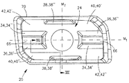
ある実施形態では、インサートポケットは、その中に形成された取り付け面32を備え、上述の底面24と係合する。底面24と取り付け面32は、一般に補完的に形づくられるように形成される。底面24は、その詳細が後述されるように、例えば、それに形成された複数の係合面を備えて取り付け面32に形成された個々の面と係合する。例えば、ある実施形態では、底面24の係合面は、2つの第1傾斜面34、2つの第2傾斜面36、2つの内側傾斜面38、2つの第1コーナー面40、および2つの第2コーナー面42を備える。
In certain embodiments, the insert pocket includes a mounting
係合面は、複数の係合作用面、すなわち、例えば図2−10に示される構成において取り付け面32のそれぞれの面に作用的に係合する係合面を備える。係合作用面は、作用する第1および第2の傾斜面34´36´、作用する内側傾斜作用面38´、および作用する第1および第2のコーナー面40´、42´を含むことができ、これらの面は、取り付け面32に形成された、第1および第2の傾斜壁44、46、内側傾斜壁48、および第1および第2の支持面50、52とそれぞれ作用的に係合する。
The engagement surface comprises a plurality of engagement surfaces, i.e., engagement surfaces that are operatively engaged with respective surfaces of the mounting
ある実施形態では、係合面は、さらに、複数の非作用係合面を備える。非作用係合面は、例えば、第1および第2の非作用傾斜面34´´、36´´、非作用内側傾斜面38´´および第1および第2のコーナー面40´´、42´´を含むことができる。例えば、他の構成の切削インサート20では、非作用係合面の1つまたはそれ以上が係合作用面となり、また、逆に係合作用面が非作用係合面となることもある。
In certain embodiments, the engagement surface further comprises a plurality of non-acting engagement surfaces. The non-acting engagement surfaces include, for example, first and second non-acting inclined surfaces 34 ″, 36 ″, non-acting inner
ある実施形態では、例えば、上述の係合作用面、すなわち、間隔をおいた第1および第2の傾斜作用面34´、36´、内側傾斜作用面38´、および第1および第2のコーナー作用面40´、42´は、取り付け面32と作用的に係合する唯一の面である。さらに、ある実施形態では、例えば、上述の係合作用面は、インサートポケットの小壁54と係合する小側部30の1つに形成された追加の係合面と共に、インサートポケット18と作用的に係合する切削インサート20の唯一の面である。
In some embodiments, for example, the engagement working surfaces described above, i.e., spaced first and second inclined working surfaces 34 ', 36', inner inclined working surfaces 38 ', and first and second corners. The working surfaces 40 ′, 42 ′ are the only surfaces that are operatively engaged with the mounting
従って、切削インサートの底面24は、2組の協働係合面で、ある時間にはその1組だけが作用することができる協働係合面を具えるものとみなすことができる。係合面34´、36´、38´、40´、および42´が、第1の組の協働係合面を構成し、係合面34´´、36´´、38´´、40´´および42´´が第2の組の協働係合面を構成する。さらに、ある実施形態では、それぞれの組は、関連した小側部30に形成された追加の係合面によって増すようにしてもよい。
Thus, the
ある実施形態では、中央貫通孔56は、切削インサート20に形成されて、締め付けネジ58を受け入れ、一方、この締め付けネジが切削インサート20をインサートポケット18内に固定する。貫通孔56は、切削インサート20の略中央の部分に形成され、上面22と底面24との間に延在するようにしてもよい。貫通孔56は貫通孔軸T1を有する。ネジ穴60は、取り付け面32に形成されて、締め付けネジ58がその中にねじ込まれるのを受け入れる。
In certain embodiments, the central through
ある実施形態では、例えば、切削インサート20は、図6に示すように、それを底から見たとき、概略矩形の輪郭を有している。これらの実施形態による切削インサートは、貫通孔軸T1に関して180度の割り出しが可能であり、2つの切削コーナー64を備えている。
In one embodiment, for example, the cutting
本発明の他の実施形態によれば、切削インサート20は、例えば図5に示されるように、その底部から見た場合概略四角い輪郭を有している。切削インサート20は、これらの他の実施形態によれば、貫通孔軸T1に関して90度で割り出しが可能であり、4つの切削コーナー64を備えている。
According to another embodiment of the present invention, the cutting
切削インサート20の第1の中間平面M1は、一般に貫通孔軸T1を通って延在し、後述される、底面24に形成される主窪み面66そのそれぞれを2等分する。切削インサート20の第2の中間の平面M2は、一般に、貫通孔軸T1を通って延在し(貫通孔軸で第1中間平面M1を横切る)、第1中間平面M1と直角である。2つの主窪み面66は、第2の中間の平面M2に関して互いに反対側に位置し、例えばコーナー面42に対して凹んだ面とされる。
The first intermediate plane M1 of the cutting
ある実施形態では、第1および第2のコーナー面40、42は、底面24の4つのコーナーに1つ置きに位置する。第1および第2のコーナー面40、42は、平面または略平面とすることができ、および/または、一般に矩形の形または他の適切な形をとることができる。ある実施形態では、コーナー面は、底面24およびその中央の面86と同一平面である。他の実施形態では、コーナー面40、42は、切削インサート20の一番底の部分を構成し、中央面86を含む、底面24上に形成された他の面に対して、上面22から離れる方向に突出している。
In one embodiment, the first and second corner surfaces 40, 42 are located at every other corner of the
第1および第2のコーナー作用面40´、42´は、第1および第2の支持面50、52と、第1および第2の非傾斜コーナー係合領域72、74において係合する。第1および第2の非傾斜コーナー係合領域72、74と、後述される他の係合領域、すなわち、2つの傾斜係合領域80、82および内側傾斜領域88は、一般に長円形の形を有するように示されているが、この形は、例示を目的とするために選ばれたものである。係合領域72、74、80、82、88は、この点に制限されず、それぞれ適切などのような形でもとることができ、例えば、関連する個々の係合作用面の形状に基づいた形とすることができる。しかしながら、切削インサートの底面24のそれぞれの組の協働係合面(34´、36´、38´、40´および42´または34´´、36´´、38´´、40´´、および42´´)は、傾斜および非傾斜の係合領域を含むことが分かる。
The first and second
ある実施形態では、例えば、非傾斜コーナー係合領域72、74は、コーナー係合面と同じ面にあり、例えば、このコーナー係合面は、一般に、第1および第2の中間面M1、M2に垂直である。従って、非傾斜コーナー係合領域72、74は、それぞれ底面24の平らな部分によって規定されるような平面にあり、また、第1および第2の中間平面M1、M2の両方と直角を成す。第1および第2の支持面50、52は、取り付け面32をインサートポケット18の外面78に接続させている外縁76に隣接して配置されている。第1および第2の支持面50、52は平面あるいは略平面とすることができ、または例えば、コーナー作用面40´、42´と良好な係合をすることができるような、他の適切な形をとることができる。
In some embodiments, for example, the non-inclined
第1の傾斜面34は、それぞれの主窪み面66の第1の側から下および外側に傾斜し、それぞれの第2のコーナー面42に向かっている。同様に、第2の傾斜面36は、それぞれの主窪み面66の第2の側から下および外側に傾斜し、それぞれの第1コーナー面40に向かっている。第1および第2の傾斜面は、同一の面とすることができ、および/または、平面とすることができ、あるいは他の適切な形をとることができる。
The first inclined surfaces 34 are inclined downward and outward from the first side of the respective main depression surfaces 66 and are directed toward the respective second corner surfaces 42. Similarly, the second
第1および第2の傾斜作用面34´、36´は、第1および第2の傾斜係合領域80、82における第1および第2の傾斜壁44、46とそれぞれ係合する。第1および第2の傾斜壁44、46は、平面とすることができ、または他の適切な形、例えば、それぞれの第1および第2の傾斜作用面34´、36´と良好な係合を実現できる形をとることができる。
The first and second inclined working surfaces 34 ′ and 36 ′ engage with the first and second
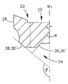
ある実施形態では、傾斜係合領域80、82は、傾斜係合面と同じ面にあり、この傾斜係合面は、例えば図7に示すように、第1中間平面M1と鋭角αをなす。ある実施形態では、例えば鋭角αは75度を超えず、これに対し、他の実施形態では、鋭角αは他の適切な値をとる。
In an embodiment, the
底面24は、概略その中央の領域に配置された中央面86を含むことができる。内側傾斜面38は、中央面86の両側から上方および外側に傾斜し、それぞれの大側部28に向かうようにすることができる。内側傾斜面38は、平面であるか、または他の適切な形をとることができる。
The
内側傾斜作用面38´は、内側傾斜係合領域88で内側の傾斜壁48と係合する。内側傾斜面38の実際の寸法は変えることができる。それは、内側傾斜壁48と係合するのは内側傾斜係合領域88だけだからである。従って、内側傾斜面38は、必要に応じてどのような程度にでも延在することができる。内側の傾斜壁48は、取り付け面32の中央の領域90から上方に傾斜し大壁84に向かっている。内側傾斜壁48は、平面であるか、または他の適切な形、例えば、内側傾斜作用面38´との良好な係合を達成する形をとることができる。
The inner inclined working
ある実施形態では、内側傾斜係合領域88は内側傾斜係合面にあり、例えば図7に示すように、第1中間平面M1との間で鈍角βを形成し、一方で、鋭角αと鈍角βは、第1中間平面M1から同じ方向に測定される。例えば、鋭角αと鈍角βの両方とも、その測定は、第1中間平面M1の底部分から開始し、時計回りの方向に進むことによって行われる。他の実施形態では、例えば鈍角βが105度を超え、一方で、他の実施形態では、鈍角βがたの適切な値をとる。これによって、例えば、インサートポケット18内に切削インサート20を安定して配置することができる。
In an embodiment, the inner
ある実施形態では、取り付け面32は、外側溝92および内側溝94を備え、それぞれの中に第1および第2のコーナー面40´´、42´´をそれぞれ受け入れる。内側溝94は、大壁84と取り付け面32に形成された内側突出面96との間に延在する。外側溝92は、大壁84と、例えば図8に示すように、取り付け面32に形成された外側突出面98との間に延在する。
In one embodiment, the mounting
ある実施形態では、第1の非作用コーナー面40´´は、外側溝92の中に受け入れられるが、それと接触はしない。第2の非作用コーナー面42´´は、内側溝94の中に受け入れられるが、それと接触はしない。同様に、内側および外側突出面96、98は、例えば、図9に示され、また、この図を参照して後述されるように、取り付け面32の他の面に対して突出するが、それぞれの主窪み面66と接触はしない。
In some embodiments, the first
ある実施形態では、非傾斜コーナー係合領域72、74は、傾斜係合領域80、82から相対的にそれぞれ間隔がおかれる。例えば、第1の非傾斜コーナー係合領域72と第1の傾斜係合領域80との間の平均距離は、切削インサート20の全体の幅の少なくとも60パーセントとすることができる。様々な係合領域の間の相対的に大きな間隔によって、例えば、インサートポケット18における切削インサート20のしっかり固定された、安定した配置を達成することができる。本発明によれば、非傾斜コーナー係合領域72、74は、第1中間平面M1の片側に配置され、傾斜および内側の傾斜係合領域80、82、88は、第1中間平面M1の逆の側に配置される。
In some embodiments, the non-tilted
ネジ穴60は、ネジ穴軸T2を有している。ある実施形態では、ネジ穴60と貫通孔56は、実質的に同心またはほぼ同心である。すなわち、貫通孔軸T1およびネジ穴軸T2が一致し、またはほとんど一致するなどとすることができる。例えば、貫通孔軸T1およびネジ穴軸T2は、両方とも、第1中間平面M1に含まれるようにすることができる。
The
図9および10を参照すると、切削部16が示される。
With reference to FIGS. 9 and 10, a
上述したように、底面24は、取り付け面32と、例えば、上記の係合領域72、74、80、82、88だけで係合することができる。例えば、図9に示すように、第2の傾斜作用面36´は、第2の傾斜壁46と係合し、また、第2のコーナー作用面42´は、第2の支持面52と係合し、一方で、主窪み面66は外側突出面98と係合せず、また、非作用第1コーナー面40´´は外側溝92と係合しない。図10に示すように、内側傾斜作用面38´は、内側の傾斜壁48と係合し、一方で、中央面86は、中央領域90と係合しない。さらに、それぞれの内側傾斜面38´、38´´は、それぞれの大側部28に形成された側方窪み部49に位置することができ、この側方窪み部49は切削インサートの底面24に連なっている。さらに、例えば、上述のように、大側部28は、大壁84と係合しない。
As described above, the
すでに指摘されているように、内側傾斜面38の実際のサイズは変えることができる。なぜなら、内側傾斜壁48と係合するのは内側傾斜係合領域88だけであるからである。従って、内側傾斜面38は、必要に応じてどの程度にでも延在することができる。ある実施形態では、図11に示すように、内側傾斜面38およびそれらに関連する側方窪み部49は、隣接している小側部30まで延在し、それによって、例えば第1コーナー面40のサイズを小さくすることができる。これによって、第1コーナー作用面40´が第1の支持面50と接触する面積をある程度小さくするが、第2コーナー作用面42´が第2の支持面52と接触する面積が変化しないようにすることができる。そのような実施形態では、側方窪み部49は、一端が開口であり、相対的な小側部30に開いている。内側傾斜面38の平面性を増すために内側傾斜面38を研削することが必要な場合、そのような実施形態は有益である。
As already pointed out, the actual size of the
他の実施形態では、図12に示すように、内側傾斜面38は、両方の小側部30まで延在する。そのような実施形態は、内側傾斜面38の研削をより容易で効率的にする。しかし、第1および第2のコーナー40、42の両方のサイズは、小さくなる。
In other embodiments, the
1つ以上の具体的な実施形態について本発明を説明したが、その説明は、概して説明に役立つものであることを意図したものであり、本発明を、示された実施形態に限定すると解釈されるものではない。本明細書に特に示されないが、本発明の範囲内にある様々な部分修正があり得ることは、当業者には、理解できることである。 Although the invention has been described with respect to one or more specific embodiments, the description is intended to be generally illustrative and is to be construed as limiting the invention to the illustrated embodiments. It is not something. Those skilled in the art will appreciate that there may be various partial modifications that are not specifically shown herein but are within the scope of the present invention.
Claims (17)
前記少なくもの1つの切削部は、
その中に着脱自在に保持される切削インサート(20)を有するインサートポケット(18)であって、前記切削インサート(20)が、上面(22)、底面(24)および前記上面と底面との間に延在する周囲面(26)を有し、前記周囲面(26)が2つの対向する大側部(28)と2つの対向する小側部(30)を備え、前記底面(24)が複数の係合面を備え、その複数の係合面における複数の係合作用面が取り付け面(32)と係合する、インサートポケット(18)を備え、
前記複数の係合作用面は、
間隔が置かれた第1および第2の傾斜作用面(34´、36´)であって、それぞれの傾斜係合領域(80、82)が、切削インサート(20)の中間部分を通って延在する仮想の第1中間平面(M1)との間で鋭角(α)を形成している第1の平面に存在する、第1および第2の傾斜作用面(34´、36´)と、
内側傾斜作用面(38’)であって、その個々の内側傾斜係合領域(88)が、前記第1中間平面(M1)と鈍角(β)を形成している第2の平面に存在し、前記鋭角および鈍角(α、β)が前記第1中間平面(M1)から同じ方向に測定したものである、内側傾斜作用面(38’)と、
第1および第2のコーナー作用面(40´、42´)であって、それらの個々の非傾斜コーナー係合領域(72、74)が、前記切削インサート(20)の前記第1中間平面(M1)と切削インサート(20)の中間部分を通って延在する仮想の第2の中間平面(M2)に略直角な第3平面に存在し、前記第2中間平面(M2)が前記第1中間平面(M1)と直角である、第1および第2のコーナー作用面(40´、42´)と、
を備え、
前記第1および第2の傾斜作用面(34´、36´)と前記内側傾斜作用面(38’)は、前記第1中間平面(M1)の第1の側に位置し、前記第1および第2のコーナー作用面(40´、42´)は、前記第1中間平面(M1)の第2の側に位置し、
前記第1および第2の傾斜作用面(34´、36´)は、前記第2の中間平面(M2)の互いに反対側に位置し、前記内側傾斜作用面(38’)は、前記第2の中間平面(M2)と交差し、
前記間隔が置かれた第1および第2の傾斜作用面(34´、36´)、前記内側傾斜作用面(38’)、および前記第1および第2のコーナー作用面(40´、42´)は、前記インサートポケット(18)の取り付け面(32)と係合する、前記切削インサート上の唯一の面であることを特徴とする切削工具。 In a cutting tool comprising at least one cutting part,
The at least one cutting part is:
An insert pocket (18) having a cutting insert (20) removably held therein, wherein the cutting insert (20) has a top surface (22), a bottom surface (24) and between the top and bottom surfaces. A peripheral surface (26) extending to the surface, the peripheral surface (26) comprising two opposing large side portions (28) and two opposing small side portions (30), wherein the bottom surface (24) An insert pocket (18) comprising a plurality of engagement surfaces, wherein a plurality of engagement working surfaces in the plurality of engagement surfaces engage the attachment surface (32);
The plurality of engagement working surfaces are:
Spaced first and second inclined working surfaces (34 ', 36'), each inclined engagement region (80, 82) extending through an intermediate portion of the cutting insert (20). First and second inclined working surfaces (34 ′, 36 ′) existing in a first plane forming an acute angle (α) with an existing virtual first intermediate plane (M1);
An inner inclined working surface (38 '), each inner inclined engaging region (88) being present in a second plane forming an obtuse angle (β) with said first intermediate plane (M1). An inner inclined working surface (38 ′), wherein the acute angle and obtuse angle (α, β) are measured in the same direction from the first intermediate plane (M1);
First and second corner working surfaces (40 ', 42'), their respective non-inclined corner engaging regions (72, 74), the first intermediate plane (20) of the cutting insert (20) M1) and the cutting insert (20) are located in a third plane substantially perpendicular to a virtual second intermediate plane (M2) extending through the intermediate portion of the cutting insert (20) , and the second intermediate plane (M2) is the first First and second corner action surfaces (40 ', 42') perpendicular to the midplane (M1);
With
The first and second tilting action surfaces (34 ', 36') and the inner tilting action surface (38 ') are located on a first side of the first intermediate plane (M1), and The second corner working surface (40 ', 42') is located on the second side of the first intermediate plane (M1),
The first and second tilting action surfaces (34 ′, 36 ′) are located on opposite sides of the second intermediate plane (M2), and the inner tilting action surface (38 ′) is the second tilting action surface (38 ′). Intersects the middle plane (M2) of
The spaced first and second inclined working surfaces (34 ', 36'), the inner inclined working surface (38 '), and the first and second corner acting surfaces (40', 42 '). ) Is the only surface on the cutting insert that engages the mounting surface (32) of the insert pocket (18).
前記インサートポケット(18)は、ネジ穴(60)を備えて、その中に締め付けネジ(58)がねじ込まれるのを受け入れ、前記ネジ穴(60)がネジ穴軸(T2)を有し、前記貫通孔軸(T1)および前記ネジ穴軸(T2)は、両方とも前記第1中間平面(M1)に含まれていることを特徴とする請求項1に記載の切削工具(10)。 The cutting insert (20) comprises a central through hole (56) and receives a clamping screw (58) therein, the through hole (56) having a through hole axis (T1),
The insert pocket (18) comprises a screw hole (60) into which a clamping screw (58) is screwed, the screw hole (60) having a screw hole axis (T2), The cutting tool (10) according to claim 1, wherein the through-hole axis (T1) and the screw hole axis (T2) are both included in the first intermediate plane (M1).
上面(22)、底面(24)およびこれらの面の間に延在する周囲面(26)であって、前記周囲面(26)が2つの対向する大側部(28)および2つの対抗する小側部(30)を備えた、上面(22)、底面(24)および周囲面(26)を備え、
前記底面(24)は、
前記切削インサート(20)の前記第2中間平面(M2)の反対側に位置する2つの窪んだ主窪み面(66)と、
前記底面(24)の4つの個々のコーナーに交互に位置する、2対の第1および第2のコーナー面(40、42)と、
2対の第1および第2の傾斜面(34、36)であって、前記傾斜面(34、36)のそれぞれが、それぞれの主窪み面(66)からそれぞれのコーナー面(40、42)に向かって、下方および外方に傾斜している第1および第2の傾斜面(34、36)と、
前記底面(24)の略中央の領域に位置する中央面(86)と、
2つの内側傾斜面(38)であって、前記第1中間平面(M1)の両側において前記底面(24)のそれぞれ反対側に位置し、前記第1中間平面(M1)に関して前記中央面(86)のそれぞれ反対側からそれぞれの大側部(28)に向けて、上方および外方に傾斜し、それぞれの前記内側傾斜面(38)は、対応する大側部(28)に形成される、側方の窪み部(49)内に位置する、内側傾斜面(38)と、
を備え、
前記2対の第1および第2のコーナー面(40、42)、前記2対の第1および第2の傾斜面(34、36)、および前記2つの内側傾斜面(38)は、共に、2組の協働係合面を構成し、それぞれの組は、前記切削インサートを着座させるための傾斜および非傾斜係合領域の両方を含み、
所定の組の傾斜係合領域は、第1中間平面(M1)の第1の側にあり、その同じ組の非傾斜係合領域は、第1中間平面(M1)の第2の側にあり、
それぞれの内側傾斜面(38)とそれに関連する側方窪み部(49)は、隣接する大側部(28)まで延在することを特徴とする切削インサート(20)。 In a cutting insert (20) having virtual first and second intermediate planes (M1, M2) perpendicular to each other and extending through the intermediate portion of the cutting insert (20), respectively.
A top surface (22), a bottom surface (24) and a peripheral surface (26) extending between the surfaces, said peripheral surface (26) having two opposing large sides (28) and two opposing surfaces Comprising a top surface (22), a bottom surface (24) and a peripheral surface (26) with a small side (30);
The bottom surface (24)
Two recessed main recessed surfaces (66) located on the opposite side of the second intermediate plane (M2) of the cutting insert (20);
Two pairs of first and second corner surfaces (40, 42) alternately positioned at four individual corners of the bottom surface (24);
Two pairs of first and second inclined surfaces (34, 36), each of the inclined surfaces (34, 36) extending from a respective main recess surface (66) to a respective corner surface (40, 42). First and second inclined surfaces (34, 36) inclined downward and outward toward
A central surface (86) located in a substantially central region of the bottom surface (24);
Two inner inclined surfaces (38), located on opposite sides of the bottom surface (24) on both sides of the first intermediate plane (M1), and the central plane (86) with respect to the first intermediate plane (M1). ) From the opposite sides to the respective large side portions (28) and inclined upward and outward, and each said inner inclined surface (38) is formed on the corresponding large side portion (28) . An inner sloping surface (38) located in the side recess (49);
With
The two pairs of first and second corner surfaces (40, 42), the two pairs of first and second inclined surfaces (34, 36), and the two inner inclined surfaces (38), Comprising two sets of cooperating engagement surfaces, each set including both inclined and non-inclined engagement areas for seating the cutting insert;
The predetermined set of inclined engagement areas is on the first side of the first intermediate plane (M1), and the same set of non-inclined engagement areas is on the second side of the first intermediate plane (M1). ,
Cutting insert (20) characterized in that each inner sloping surface (38) and its associated side recess (49) extend to the adjacent large side (28).
前記内側傾斜面(38)のうちの1つの係合領域(88)が、前記第1中間平面(M1)と鈍角(β)を形成している第2の平面に存在し、
前記鋭角および鈍角(α、β)が、第1中間平面(M1)から同じ方向に測定されることを特徴とする請求項8に記載の切削インサート(20)。 The individual engagement areas (80, 82) of the inclined surfaces (34, 36) are present in a first plane forming an acute angle (α) with the first intermediate plane (M1),
One engagement region (88) of the inner inclined surface (38) is present in a second plane forming an obtuse angle (β) with the first intermediate plane (M1),
Cutting insert (20) according to claim 8, characterized in that the acute and obtuse angles (α, β) are measured in the same direction from the first intermediate plane (M1).
Applications Claiming Priority (3)
| Application Number | Priority Date | Filing Date | Title |
|---|---|---|---|
| IL195984 | 2008-12-16 | ||
| IL195984A IL195984A0 (en) | 2008-12-16 | 2008-12-16 | Cutting tool and cutting insert therefor |
| PCT/IL2009/001109 WO2010070630A1 (en) | 2008-12-16 | 2009-11-25 | Cutting tool and cutting insert therefor |
Publications (3)
| Publication Number | Publication Date |
|---|---|
| JP2012512041A JP2012512041A (en) | 2012-05-31 |
| JP2012512041A5 JP2012512041A5 (en) | 2012-11-29 |
| JP5587335B2 true JP5587335B2 (en) | 2014-09-10 |
Family
ID=41718200
Family Applications (1)
| Application Number | Title | Priority Date | Filing Date |
|---|---|---|---|
| JP2011541714A Active JP5587335B2 (en) | 2008-12-16 | 2009-11-25 | Cutting tool and cutting insert therefor |
Country Status (13)
| Country | Link |
|---|---|
| US (1) | US8313270B2 (en) |
| EP (1) | EP2361166B1 (en) |
| JP (1) | JP5587335B2 (en) |
| KR (1) | KR101588919B1 (en) |
| CN (1) | CN102245334B (en) |
| BR (1) | BRPI0923449A2 (en) |
| CA (1) | CA2742214A1 (en) |
| ES (1) | ES2563430T3 (en) |
| IL (1) | IL195984A0 (en) |
| PL (1) | PL2361166T3 (en) |
| RU (1) | RU2011129666A (en) |
| TW (1) | TW201029778A (en) |
| WO (1) | WO2010070630A1 (en) |
Families Citing this family (19)
| Publication number | Priority date | Publication date | Assignee | Title |
|---|---|---|---|---|
| JP5024189B2 (en) * | 2008-06-04 | 2012-09-12 | 株式会社タンガロイ | Tip temporary fixing mechanism and throw-away cutting tool having the same |
| US8821079B2 (en) * | 2012-03-06 | 2014-09-02 | Iscar, Ltd. | Cutting tool and cutting insert therefor |
| KR101452073B1 (en) * | 2012-12-24 | 2014-10-16 | 대구텍 유한회사 | Cutting insert and milling cutter having the same |
| US9120154B2 (en) * | 2013-02-14 | 2015-09-01 | Iscar, Ltd. | Single-sided square-shaped indexable cutting insert and cutting tool |
| US9120156B2 (en) * | 2013-03-26 | 2015-09-01 | Iscar, Ltd. | Rhombus-shaped indexable cutting insert and cutting tool |
| US9481038B2 (en) * | 2013-12-11 | 2016-11-01 | Iscar, Ltd. | Cutting insert having a dovetail anti-slip arrangement |
| US9339873B2 (en) * | 2013-12-11 | 2016-05-17 | Iscar, Ltd. | Cutting insert having a dovetail anti-slip arrangement |
| USD738412S1 (en) * | 2013-12-25 | 2015-09-08 | Taegutec Ltd. | Cutting insert |
| EP2992991A1 (en) * | 2014-09-05 | 2016-03-09 | Sandvik Intellectual Property AB | Cutting insert and milling tool |
| USD752664S1 (en) * | 2014-09-25 | 2016-03-29 | Taegutec Ltd. | Cutting insert |
| CN104400098B (en) * | 2014-11-24 | 2019-02-05 | 马鞍山市恒利达机械刀片有限公司 | A kind of double milling combination knives of mechanical quick-replaceable type aluminium ingot |
| WO2016084891A1 (en) * | 2014-11-27 | 2016-06-02 | 株式会社タンガロイ | Cutting insert and replaceable-edge rotary cutting tool |
| JP6066391B1 (en) * | 2015-06-19 | 2017-01-25 | 株式会社タンガロイ | Tool bodies and cutting tools |
| US10279400B2 (en) * | 2017-01-30 | 2019-05-07 | Iscar, Ltd. | Indexable, single-sided cutting insert having two clamping bores and cutting tool therefor |
| US10112242B1 (en) * | 2017-04-21 | 2018-10-30 | Iscar, Ltd. | Ramping insert having non-positive cutting geometry and ramping tool |
| US10406611B1 (en) * | 2018-03-28 | 2019-09-10 | Iscar, Ltd. | Cutting tool and cutting insert having complementary engagement features for eccentric mounting |
| US11090740B2 (en) * | 2019-02-12 | 2021-08-17 | Iscar, Ltd. | Rotary cutting body having insert pocket with seat surface provided with a plurality of abutment elements and rotary cutting tool |
| US11453065B2 (en) | 2019-05-24 | 2022-09-27 | Iscar, Ltd. | Cutting insert having lower anti-slip recess, insert holder and cutting tool |
| US11717895B2 (en) * | 2021-05-21 | 2023-08-08 | Taegutec Ltd. | Cutting insert and cutting tool assembly including same |
Family Cites Families (12)
| Publication number | Priority date | Publication date | Assignee | Title |
|---|---|---|---|---|
| IL119113A (en) * | 1996-08-22 | 2000-10-31 | Iscar Ltd | Cutting insert |
| SE511390C2 (en) | 1997-03-05 | 1999-09-20 | Sandvik Ab | Device for clamping cutting plates for cutting metal machining |
| DE19848045C2 (en) * | 1998-10-17 | 2002-01-31 | Fette Wilhelm Gmbh | Insert milling cutters |
| SE520628C2 (en) * | 2001-01-09 | 2003-08-05 | Sandvik Ab | Tools and cutting body for chip separating machining where the coupling surfaces have matching grooves and ridges |
| SE526109C2 (en) * | 2003-03-17 | 2005-07-05 | Seco Tools Ab | Milling tools and indexable inserts with cooperating projections and recesses |
| JP2006110667A (en) * | 2004-10-14 | 2006-04-27 | Mitsubishi Materials Corp | Cutting insert |
| SE528811C2 (en) * | 2005-03-16 | 2007-02-20 | Sandvik Intellectual Property | Cuts and tools for chip separating machining with angled engaging means, and additives for such tools |
| DE102005032653B3 (en) * | 2005-07-13 | 2006-11-30 | Fette Gmbh | Production process for positive connection between tool insert and carrier |
| WO2007049617A1 (en) * | 2005-10-28 | 2007-05-03 | Kyocera Corporation | Cutting insert, milling tool, and cutting method |
| SE0600876L (en) * | 2006-04-20 | 2007-10-21 | Sandvik Intellectual Property | Tools and inserts for chip separating machining with primary and secondary meshes with rotationally symmetrical shape |
| SE530631C2 (en) | 2006-12-12 | 2008-07-22 | Sandvik Intellectual Property | Tools and cutters for chip separating machining |
| SE530629C2 (en) | 2006-12-12 | 2008-07-22 | Sandvik Intellectual Property | Tools and basic body for chip separating machining including an elastically deformable spring in the cutting position |
-
2008
- 2008-12-16 IL IL195984A patent/IL195984A0/en unknown
-
2009
- 2009-11-11 US US12/616,629 patent/US8313270B2/en active Active
- 2009-11-25 KR KR1020117013610A patent/KR101588919B1/en active IP Right Grant
- 2009-11-25 BR BRPI0923449A patent/BRPI0923449A2/en not_active IP Right Cessation
- 2009-11-25 RU RU2011129666/02A patent/RU2011129666A/en not_active Application Discontinuation
- 2009-11-25 CA CA2742214A patent/CA2742214A1/en not_active Abandoned
- 2009-11-25 JP JP2011541714A patent/JP5587335B2/en active Active
- 2009-11-25 PL PL09795821T patent/PL2361166T3/en unknown
- 2009-11-25 CN CN200980150418.8A patent/CN102245334B/en active Active
- 2009-11-25 ES ES09795821.9T patent/ES2563430T3/en active Active
- 2009-11-25 WO PCT/IL2009/001109 patent/WO2010070630A1/en active Application Filing
- 2009-11-25 EP EP09795821.9A patent/EP2361166B1/en active Active
- 2009-12-11 TW TW098142580A patent/TW201029778A/en unknown
Also Published As
| Publication number | Publication date |
|---|---|
| PL2361166T3 (en) | 2016-06-30 |
| CN102245334A (en) | 2011-11-16 |
| BRPI0923449A2 (en) | 2016-01-12 |
| EP2361166B1 (en) | 2016-01-06 |
| RU2011129666A (en) | 2013-01-27 |
| KR101588919B1 (en) | 2016-01-26 |
| CA2742214A1 (en) | 2010-06-24 |
| CN102245334B (en) | 2014-08-13 |
| JP2012512041A (en) | 2012-05-31 |
| IL195984A0 (en) | 2009-09-01 |
| US20100150670A1 (en) | 2010-06-17 |
| US8313270B2 (en) | 2012-11-20 |
| KR20110099013A (en) | 2011-09-05 |
| WO2010070630A1 (en) | 2010-06-24 |
| ES2563430T3 (en) | 2016-03-15 |
| EP2361166A1 (en) | 2011-08-31 |
| TW201029778A (en) | 2010-08-16 |
Similar Documents
| Publication | Publication Date | Title |
|---|---|---|
| JP5587335B2 (en) | Cutting tool and cutting insert therefor | |
| JP4588716B2 (en) | Rotary groove milling and its cutting insert | |
| US6929429B2 (en) | Milling tool and cutting insert therefor | |
| KR101314765B1 (en) | Drilling Insert And Drilling Tool | |
| JP3834067B2 (en) | Modular cutting tool assembly | |
| US7407347B2 (en) | Tool for chip removing machining | |
| US20200368830A1 (en) | Indexable rotary cutting tool and tool body | |
| KR100807071B1 (en) | Rotary cutting tool | |
| JP2004521767A (en) | Cutting tools and their cutting inserts | |
| KR20100016472A (en) | Cutting insert cutting eight ways, and tool holder for same | |
| JP2008188763A (en) | Cutting tool, cutting insert and tool main body | |
| KR20100016473A (en) | Cutting insert cutting eight ways, and tool holder for same | |
| JP2005153140A (en) | Chip removing machining tool | |
| KR102362021B1 (en) | A cutting tool and a cutting insert for a chip-removing tool | |
| TWI814943B (en) | Rotary cutting body having insert pocket with seat surface provided with a plurality of abutment elements and rotary cutting tool | |
| JP4784878B2 (en) | Side cutter | |
| TW202218779A (en) | Reversible square-shaped cutting insert and rotary cutting tool | |
| KR102625931B1 (en) | Cutting inserts and milling tools | |
| JP7374085B2 (en) | Slitting cutter and tool key combined with it | |
| MXPA01008851A (en) | Metal cutting tool with direct cutting plate arrangement. | |
| WO2016171174A1 (en) | Cutting tool and method for manufacturing cut article | |
| US11597019B2 (en) | Slotting tool body having insert receiving slots connected by flexibility recess and rotary slot cutting tool having same |
Legal Events
| Date | Code | Title | Description |
|---|---|---|---|
| A521 | Request for written amendment filed |
Free format text: JAPANESE INTERMEDIATE CODE: A523 Effective date: 20121009 |
|
| A621 | Written request for application examination |
Free format text: JAPANESE INTERMEDIATE CODE: A621 Effective date: 20121009 |
|
| A977 | Report on retrieval |
Free format text: JAPANESE INTERMEDIATE CODE: A971007 Effective date: 20131018 |
|
| A131 | Notification of reasons for refusal |
Free format text: JAPANESE INTERMEDIATE CODE: A131 Effective date: 20131029 |
|
| A521 | Request for written amendment filed |
Free format text: JAPANESE INTERMEDIATE CODE: A523 Effective date: 20140129 |
|
| TRDD | Decision of grant or rejection written | ||
| A01 | Written decision to grant a patent or to grant a registration (utility model) |
Free format text: JAPANESE INTERMEDIATE CODE: A01 Effective date: 20140624 |
|
| A61 | First payment of annual fees (during grant procedure) |
Free format text: JAPANESE INTERMEDIATE CODE: A61 Effective date: 20140723 |
|
| R150 | Certificate of patent or registration of utility model |
Ref document number: 5587335 Country of ref document: JP Free format text: JAPANESE INTERMEDIATE CODE: R150 |
|
| R250 | Receipt of annual fees |
Free format text: JAPANESE INTERMEDIATE CODE: R250 |
|
| R250 | Receipt of annual fees |
Free format text: JAPANESE INTERMEDIATE CODE: R250 |
|
| R250 | Receipt of annual fees |
Free format text: JAPANESE INTERMEDIATE CODE: R250 |
|
| R250 | Receipt of annual fees |
Free format text: JAPANESE INTERMEDIATE CODE: R250 |
|
| R250 | Receipt of annual fees |
Free format text: JAPANESE INTERMEDIATE CODE: R250 |
|
| R250 | Receipt of annual fees |
Free format text: JAPANESE INTERMEDIATE CODE: R250 |
|
| R250 | Receipt of annual fees |
Free format text: JAPANESE INTERMEDIATE CODE: R250 |