JP5584440B2 - Fan casing for gas turbine engine - Google Patents
Fan casing for gas turbine engine Download PDFInfo
- Publication number
- JP5584440B2 JP5584440B2 JP2009176036A JP2009176036A JP5584440B2 JP 5584440 B2 JP5584440 B2 JP 5584440B2 JP 2009176036 A JP2009176036 A JP 2009176036A JP 2009176036 A JP2009176036 A JP 2009176036A JP 5584440 B2 JP5584440 B2 JP 5584440B2
- Authority
- JP
- Japan
- Prior art keywords
- fan
- blade
- casing
- blades
- fan casing
- Prior art date
- Legal status (The legal status is an assumption and is not a legal conclusion. Google has not performed a legal analysis and makes no representation as to the accuracy of the status listed.)
- Expired - Fee Related
Links
Images


Classifications
-
- F—MECHANICAL ENGINEERING; LIGHTING; HEATING; WEAPONS; BLASTING
- F01—MACHINES OR ENGINES IN GENERAL; ENGINE PLANTS IN GENERAL; STEAM ENGINES
- F01D—NON-POSITIVE DISPLACEMENT MACHINES OR ENGINES, e.g. STEAM TURBINES
- F01D21/00—Shutting-down of machines or engines, e.g. in emergency; Regulating, controlling, or safety means not otherwise provided for
- F01D21/04—Shutting-down of machines or engines, e.g. in emergency; Regulating, controlling, or safety means not otherwise provided for responsive to undesired position of rotor relative to stator or to breaking-off of a part of the rotor, e.g. indicating such position
- F01D21/045—Shutting-down of machines or engines, e.g. in emergency; Regulating, controlling, or safety means not otherwise provided for responsive to undesired position of rotor relative to stator or to breaking-off of a part of the rotor, e.g. indicating such position special arrangements in stators or in rotors dealing with breaking-off of part of rotor
-
- F—MECHANICAL ENGINEERING; LIGHTING; HEATING; WEAPONS; BLASTING
- F01—MACHINES OR ENGINES IN GENERAL; ENGINE PLANTS IN GENERAL; STEAM ENGINES
- F01D—NON-POSITIVE DISPLACEMENT MACHINES OR ENGINES, e.g. STEAM TURBINES
- F01D11/00—Preventing or minimising internal leakage of working-fluid, e.g. between stages
- F01D11/08—Preventing or minimising internal leakage of working-fluid, e.g. between stages for sealing space between rotor blade tips and stator
- F01D11/12—Preventing or minimising internal leakage of working-fluid, e.g. between stages for sealing space between rotor blade tips and stator using a rubstrip, e.g. erodible. deformable or resiliently-biased part
- F01D11/122—Preventing or minimising internal leakage of working-fluid, e.g. between stages for sealing space between rotor blade tips and stator using a rubstrip, e.g. erodible. deformable or resiliently-biased part with erodable or abradable material
-
- F—MECHANICAL ENGINEERING; LIGHTING; HEATING; WEAPONS; BLASTING
- F01—MACHINES OR ENGINES IN GENERAL; ENGINE PLANTS IN GENERAL; STEAM ENGINES
- F01D—NON-POSITIVE DISPLACEMENT MACHINES OR ENGINES, e.g. STEAM TURBINES
- F01D11/00—Preventing or minimising internal leakage of working-fluid, e.g. between stages
- F01D11/08—Preventing or minimising internal leakage of working-fluid, e.g. between stages for sealing space between rotor blade tips and stator
- F01D11/12—Preventing or minimising internal leakage of working-fluid, e.g. between stages for sealing space between rotor blade tips and stator using a rubstrip, e.g. erodible. deformable or resiliently-biased part
- F01D11/127—Preventing or minimising internal leakage of working-fluid, e.g. between stages for sealing space between rotor blade tips and stator using a rubstrip, e.g. erodible. deformable or resiliently-biased part with a deformable or crushable structure, e.g. honeycomb
-
- F—MECHANICAL ENGINEERING; LIGHTING; HEATING; WEAPONS; BLASTING
- F01—MACHINES OR ENGINES IN GENERAL; ENGINE PLANTS IN GENERAL; STEAM ENGINES
- F01D—NON-POSITIVE DISPLACEMENT MACHINES OR ENGINES, e.g. STEAM TURBINES
- F01D25/00—Component parts, details, or accessories, not provided for in, or of interest apart from, other groups
- F01D25/24—Casings; Casing parts, e.g. diaphragms, casing fastenings
-
- F—MECHANICAL ENGINEERING; LIGHTING; HEATING; WEAPONS; BLASTING
- F04—POSITIVE - DISPLACEMENT MACHINES FOR LIQUIDS; PUMPS FOR LIQUIDS OR ELASTIC FLUIDS
- F04D—NON-POSITIVE-DISPLACEMENT PUMPS
- F04D27/00—Control, e.g. regulation, of pumps, pumping installations or pumping systems specially adapted for elastic fluids
- F04D27/02—Surge control
- F04D27/0292—Stop safety or alarm devices, e.g. stop-and-go control; Disposition of check-valves
-
- F—MECHANICAL ENGINEERING; LIGHTING; HEATING; WEAPONS; BLASTING
- F04—POSITIVE - DISPLACEMENT MACHINES FOR LIQUIDS; PUMPS FOR LIQUIDS OR ELASTIC FLUIDS
- F04D—NON-POSITIVE-DISPLACEMENT PUMPS
- F04D29/00—Details, component parts, or accessories
- F04D29/02—Selection of particular materials
- F04D29/023—Selection of particular materials especially adapted for elastic fluid pumps
-
- F—MECHANICAL ENGINEERING; LIGHTING; HEATING; WEAPONS; BLASTING
- F04—POSITIVE - DISPLACEMENT MACHINES FOR LIQUIDS; PUMPS FOR LIQUIDS OR ELASTIC FLUIDS
- F04D—NON-POSITIVE-DISPLACEMENT PUMPS
- F04D29/00—Details, component parts, or accessories
- F04D29/40—Casings; Connections of working fluid
- F04D29/52—Casings; Connections of working fluid for axial pumps
- F04D29/522—Casings; Connections of working fluid for axial pumps especially adapted for elastic fluid pumps
- F04D29/526—Details of the casing section radially opposing blade tips
-
- F—MECHANICAL ENGINEERING; LIGHTING; HEATING; WEAPONS; BLASTING
- F05—INDEXING SCHEMES RELATING TO ENGINES OR PUMPS IN VARIOUS SUBCLASSES OF CLASSES F01-F04
- F05D—INDEXING SCHEME FOR ASPECTS RELATING TO NON-POSITIVE-DISPLACEMENT MACHINES OR ENGINES, GAS-TURBINES OR JET-PROPULSION PLANTS
- F05D2220/00—Application
- F05D2220/30—Application in turbines
- F05D2220/36—Application in turbines specially adapted for the fan of turbofan engines
-
- F—MECHANICAL ENGINEERING; LIGHTING; HEATING; WEAPONS; BLASTING
- F05—INDEXING SCHEMES RELATING TO ENGINES OR PUMPS IN VARIOUS SUBCLASSES OF CLASSES F01-F04
- F05D—INDEXING SCHEME FOR ASPECTS RELATING TO NON-POSITIVE-DISPLACEMENT MACHINES OR ENGINES, GAS-TURBINES OR JET-PROPULSION PLANTS
- F05D2240/00—Components
- F05D2240/20—Rotors
- F05D2240/30—Characteristics of rotor blades, i.e. of any element transforming dynamic fluid energy to or from rotational energy and being attached to a rotor
- F05D2240/303—Characteristics of rotor blades, i.e. of any element transforming dynamic fluid energy to or from rotational energy and being attached to a rotor related to the leading edge of a rotor blade
-
- F—MECHANICAL ENGINEERING; LIGHTING; HEATING; WEAPONS; BLASTING
- F05—INDEXING SCHEMES RELATING TO ENGINES OR PUMPS IN VARIOUS SUBCLASSES OF CLASSES F01-F04
- F05D—INDEXING SCHEME FOR ASPECTS RELATING TO NON-POSITIVE-DISPLACEMENT MACHINES OR ENGINES, GAS-TURBINES OR JET-PROPULSION PLANTS
- F05D2260/00—Function
- F05D2260/96—Preventing, counteracting or reducing vibration or noise
Description
本発明はガスタービンエンジンに関し、更に詳細には、このようなエンジンのファンケーシングの閉じこめ構造すなわち捕捉構造(containment arrangement)に関する。 The present invention relates to gas turbine engines, and more particularly to a fan casing containment or containment arrangement of such engines.
従来、ガスタービンエンジンのファンブレードは、ファンケーシング内に設けられたファントラックとして公知の環状の研磨性材料層内で回転する。作動では、ファンブレードは、この研磨性層内に切り込んで経路を形成し、これによって、ブレード先端周囲の漏れを最少にしている。 Conventionally, the fan blades of a gas turbine engine rotate in an annular abrasive material layer known as a fan track provided in a fan casing. In operation, the fan blade cuts into the abrasive layer to form a path, thereby minimizing leakage around the blade tip.
ファンケーシングには、ファンブレードが何らかの理由により破損した場合、外れたブレードやデブリ(破片)を捕捉するように設計された捕捉システムが、ファントラックのほぼ半径方向外方に設けられている。発生したデブリ(破片)のエネルギを吸収するため、ファンケーシングの強度及びコンプライアンスを正確に計算しなければならない。従って、ブレードが外れる事態において、ファントラックがブレードの軌跡(飛翔経路)を遮ってはならないということが重要である。従って、外れたブレードやブレードの破片が、本質的に妨げられずに、ファントラックを通って捕捉システムに到達できるように、ファントラックは比較的弱くなければならない。 The fan casing is provided with a capture system that is designed to capture loose blades and debris if the fan blade breaks for any reason, generally radially outward of the fan track. In order to absorb the energy of the generated debris (debris), the strength and compliance of the fan casing must be accurately calculated. Therefore, it is important that the fan track should not obstruct the blade trajectory (flight path) in a situation where the blade comes off. Thus, the fan track must be relatively weak so that dislodged blades and blade fragments can reach the capture system through the fan track, essentially unimpeded.
ファントラックの後方には、従来、環状氷衝突パネルが設けられていた。これは、代表的には、ガラス強化プラスチック(GPR)成型体又は何らかの他の材料で形成されたトレー又はパネルである。衝突強度を増大するため、GPRで包囲してもよい。ファンブレード上で形成した氷には、遠心力及び空気流の力の両方が作用し、これらの力の夫々により、氷をブレードからの離脱前に外方及び後方に移動する。 Conventionally, an annular ice collision panel has been provided behind the fan track. This is typically a tray or panel formed of a glass reinforced plastic (GPR) molding or some other material. In order to increase the collision strength, it may be surrounded by GPR. Both the centrifugal force and the airflow force act on the ice formed on the fan blade, and each of these forces moves the ice outward and rearward before removal from the blade.
従来のファンブレードは、氷がブレードの後縁から離脱し、離脱した氷がファントラックの後方の氷衝突パネルに当たるような形状を備えている。氷は、氷衝突パネルを損傷することなく、このパネルによって跳ね返り、又は逸らされる(偏向させられる)。 The conventional fan blade has a shape such that the ice is separated from the trailing edge of the blade, and the separated ice hits the ice collision panel at the rear of the fan track. The ice is bounced or deflected (deflected) by this panel without damaging the ice collision panel.
スウェプトファンブレードは、中央部の弦長(chord length)が従来のファンブレードよりも大きい。スウェプトファンブレードは、効率において従来のブレードよりも大きな利点を提供するため、ガスタービン産業で益々好まれている。スウェプトファンブレードは、弦長が大きいため、このようなブレード上に形成された氷は、従来のブレードにおけるのと同じ後方及び外方への経路を辿るが、後縁に達する前にブレードの半径方向外先端に達する可能性がある。従って、氷は、ブレードの先端から離脱し、ファントラックに当たる。 Swept fan blades have a larger chord length at the center than conventional fan blades. Swept fan blades are increasingly preferred in the gas turbine industry because they offer significant advantages over conventional blades in efficiency. Because swept fan blades have a large chord length, the ice formed on such blades follows the same backward and outward path as in conventional blades, but before the trailing edge is reached, the radius of the blade There is a possibility of reaching the tip out of direction. Thus, the ice breaks off from the tip of the blade and hits the fan track.
しかしながら、従来のファントラックは、氷の衝突を許容するのに十分な強度を備えておらず、そのため、従来の構成は、スウェプトファンブレードで使用するには適していない。ファントラックを強化するだけでは氷の衝突に適応することは不可能である。これは、ブレードが外れる事態中のブレードの軌跡を遮り、ファンケーシング捕捉システムの作動を損なってしまうためである。 However, conventional fan tracks are not strong enough to allow ice collisions, so the conventional configuration is not suitable for use with swept fan blades. It is impossible to adapt to ice collisions simply by strengthening the fan track. This is because the trajectory of the blade during the situation where the blade is detached is blocked, and the operation of the fan casing capturing system is impaired.
ガスタービン産業では、近年、より軽量のファンブレードを開発することもまた奨励されている。こうしたブレードは、代表的には、金属製中空構造又は複合構造のいずれかである。この開発により別の問題点が持ち上がった。ブレードが軽量であるため、従って、変形に対する抵抗が小さいため、氷の通過に対して抵抗し、しかも、外れたファンブレードの軌跡と干渉しないケーシング構成を考案するのが更に困難である。更に、軽量スウェプトブレードは、ファンケーシングとの衝突時に、従来のブレードとは異なる態様で壊れる傾向があり、従来のケーシング設計はこれに適合するように設計されていない。 The gas turbine industry has also recently been encouraged to develop lighter fan blades. Such blades are typically either metal hollow structures or composite structures. This development raised another problem. Because the blades are lightweight, and therefore less resistant to deformation, it is more difficult to devise a casing configuration that resists the passage of ice and that does not interfere with the trajectory of a detached fan blade. Furthermore, lightweight swept blades tend to break differently than conventional blades upon impact with a fan casing, and conventional casing designs are not designed to accommodate this.
概括的に述べると、ガスタービン産業における開発は、一方では、スウェプトファンブレードに向かっており、他方では、より軽量のファンブレードに向かっており、これにより、こうした構成で必要とされる三つの機能、即ち研磨性(研磨可能な)ファントラック、離脱した氷に対する抵抗、及びブレード又はブレードの破片の捕捉(すなわち、閉じこめ)、を提供するファンケーシング及び捕捉(すなわち、閉じこめ)構造の設計が益々困難になっている。 Generally speaking, developments in the gas turbine industry are on the one hand towards swept fan blades and on the other hand towards lighter fan blades, which leads to the three functions required in these configurations. More difficult to design fan casings and trapping (ie, confinement) structures that provide abrasive (abrasive) fan tracks, resistance to detached ice, and trapping (ie, confinement) of blades or blade fragments It has become.
従って、本発明の目的は、上文中に説明した問題点を実質的に解決する、複合ファンブレード又は他の軽量ファンブレードで使用するのに特に適したガスタービンエンジン用の閉じこめ(すなわち、捕捉)アッセンブリを提供することである。
上記目的を達するために、本願発明は、
ガスタービンエンジン用ファンケーシングであって、
前記エンジンは、使用時に前記エンジンの軸線を中心として回転する複数のファンブレードを備え、
前記ケーシングは、前記ファンブレードの半径方向外方に環状構造を含み、この環状構造は、前記ファンブレードの上流及び下流の両方で軸線方向に延び、使用時にファンブレードがほぼ半径方向外方に外れて前記ケーシングに当たり可能性があり、
前記ケーシングは、使用時に前記ファンブレードの半径方向外方にあるファントラックを備えた、ファンケーシングにおいて、
外れたブレードのほぼ全てが、前記ファントラックによって偏向させられる、ファンケーシングを提供するものである。
Accordingly, it is an object of the present invention to provide confinement (ie, capture) for a gas turbine engine that is particularly suitable for use with composite fan blades or other lightweight fan blades that substantially solve the problems described above. It is to provide an assembly.
In order to achieve the above object, the present invention provides:
A fan casing for a gas turbine engine,
The engine includes a plurality of fan blades that rotate about the axis of the engine when in use,
The casing includes an annular structure radially outward of the fan blade, the annular structure extending axially both upstream and downstream of the fan blade so that the fan blade is disengaged substantially radially outward in use. May hit the casing,
In the fan casing, the casing comprising a fan track that is radially outward of the fan blade in use,
It provides a fan casing in which almost all of the detached blades are deflected by the fan track.
次に、本発明の実施例を添付図面を参照して例として説明する。 Embodiments of the present invention will now be described by way of example with reference to the accompanying drawings.
先ず最初に図1を参照すると、ガスタービンエンジン10は、軸線方向で、インテーク11、ファン12、中圧コンプレッサ13、高圧コンプレッサ14、燃焼器15、高圧タービン16、中圧タービン17、及び低圧タービン18の夫々、及び排気ノズル19を備えている。
Referring first to FIG. 1, the
空気は、インテーク11を通ってエンジンに入り、ファン12によって加速され、二つの空気流を発生する。外側の空気流は、エンジン10からファンダクト(図示せず)を通って排出され、推進力を提供する。内側の空気流は、中圧コンプレッサ13に差し向けられ、ここで圧縮され、次いで高圧コンプレッサ14に差し向けられ、ここで更に圧縮される。
Air enters the engine through the
次いで、圧縮空気を燃焼器15で燃料と混合し、混合物を燃焼する。結果的に発生した燃焼生成物は、次いで、排気ノズル19を通って排気される前に、高圧タービン16、中圧タービン17、及び低圧タービン18の夫々を通って膨張し、追加の推進力を提供する。高圧タービン16、中圧タービン17、及び低圧タービン18は、高圧コンプレッサ14、中圧コンプレッサ13、及びファン12の夫々を同心の駆動シャフト20、21、22を介して駆動する。
The compressed air is then mixed with fuel in the
ファン12は、ファンディスク24に取り付けられ周方向に配列されたファンブレード23を備えている。ファン12は、ファンケーシング25によって取り囲まれている。このファンケーシング25は(図示していない別の構造とともに)ファンダクトを形成する。使用の際、ファンブレード23は、X−X軸線を中心として回転する。
The
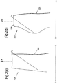
図2(a)は、従来のファンブレード123を示す。矢印Aは、氷片がブレード123の表面を横切って辿る概念的経路(想像的な経路)を示す。氷は、ブレード123の後縁126から放出され、従って、ファントラックの後方の氷衝突パネルに当たる。ブレードが外れる事態(blade-off event)では、ファンブレード123の一部又は全体がいきなり外れる。外れたブレードの軌跡には、ガスの負荷による影響がほとんど及ぼされず、そのため本質的に半径方向外方に破線矢印Bによって示すように移動し、ファントラックに当たる。
FIG. 2A shows a
図2(b)は、スウェプトファンブレード223を示す。矢印Aは、氷片がブレード223の表面を横切って辿る概念的経路(想像的な経路)を示す。この経路は、図2(a)で従来のファンブレード123の表面を横切って辿る経路と本質的に同じである。同様に、外れたファンブレード又はブレード破片の軌跡Bは、図2(a)の軌跡Bと本質的に同じである。しかしながら、図2(b)では、スウェプトブレード223の弦寸法が比較的大きいため、氷は、後縁226のところでなく、ブレードの先端228のところで放出されるということがわかる。上文中に説明した従来のファンケーシング構成では、この氷は、この場合、氷衝突パネルでなくファントラックに当たる。問題は、氷の衝突エネルギが、外れたブレード又はブレードの破片の局所的衝突エネルギよりも大きいということである。従来のファンケーシング構成は、従って、外れたファンブレード又はブレードの破片を本質的に妨げることなく捕捉システムまで通すことができるが、しかも、衝突エネルギが比較的高い外れた氷の方向を変えるという相反する(又は矛盾した)特性を備えていなければならない。
FIG. 2B shows the swept
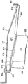
図3では、複合スウェプトファンブレード323は、エーロフォイル部分32と、ルート(根本)部分34とを備えている。エーロフォイル部分32は、複合材料製の本体36と、金属製の前縁キャップ38とを備えている。前縁キャップ38は、使用中、異物による損傷と腐蝕とから、本体36を保護する。前縁キャップ38が設けられていないと、複合材料は、異物による損傷や腐蝕により、外れたり剥離したりしてしまう。
In FIG. 3, the composite swept
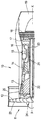
図4は、本発明によるファンケーシングの第1実施例の断面を示す。ファンケーシング625は、ガスタービンエンジンの周囲に亘って延びる。使用の際、エンジンのファンブレード623が、ファンケーシング625内で回転する。ファンブレード623は、図3に示す種類の複合スウェプトファンブレードである。
FIG. 4 shows a cross section of a first embodiment of a fan casing according to the invention.
ファンケーシング625は、鍛造により形成された二つの環状の部分、即ち、上流(前方)鍛造部662と、下流(後方)鍛造部664とを備えている。これらの上流鍛造部と下流鍛造部662、664は、フランジが設けられており、これらのフランジによりガスタービンエンジンの他の構造(図示せず)に取り付けられている。上流鍛造部662の前端には、環状のファンケースフック643が設けられている。この環状ファンケースフックの目的を以下に説明する。
The
上流鍛造部662と後方鍛造部664との間に、環状の外ケーシング666が設けられている。この外ケーシング666は、上流鍛造部662及び下流鍛造部664の夫々に溶接線668及び670に沿って溶接されている。外ケーシング666の半径方向内方には、環状の隔壁支持構造672が設けられている。この実施例では、隔壁支持構造672は、機械加工によって形成したハニカム材料層を含む。別の態様では、金属層又はポリマーフォーム層、又は構造的な充填層を含んでいてもよい。このような材料は周知であり、本明細書中、これ以上詳細には説明しない。隔壁支持構造672は、上流鍛造部662と下流鍛造部664との間を軸線方向に延びる。隔壁支持構造672は、接着剤又は機械的ファスナによって外ケーシング666に取り付けられている。
An annular
隔壁支持構造672の半径方向内面に、隔壁674が接着剤で取り付けられている。隔壁674は、前方に延びてファンケースフック643に当接している。隔壁674は、これに衝突したブレードが壊れるように比較的剛性であり且つ強く構成されている。隔壁は、ファンブレード623の先端の半径方向外方にファントラックを形成している。
A
隔壁674の半径方向内面は、研磨性コーティング678によって覆われている。使用の際、ファンブレード623の先端は、研磨性層678内に切り込んで経路を形成し、これによりブレード先端周囲の漏れを最少にする。
A radially inner surface of the
隔壁支持構造672には、更に、隔壁674の後方に音響ライナ680が設けられている。このようなライナは周知であり、使用時にファンブレード623が発生する騒音エネルギを吸収する。このような音響ライナを接着剤によって、又は機械的ファスナによって取り付けることが周知である。
The
ファンブレード623が作動中に外れた場合、ブレード623が研磨性コーティング678及び隔壁674に衝突する。
外れたファンブレード623が研磨性コーティング678及び隔壁674と接触したとき、複合材料の強度を越える大きな圧縮負荷が(ブレードの長さ方向に)発生する。
If the
When the
従って、ファンブレード623の本体636は、衝突時に壊れて比較的小さな破片になり、これらの破片は、隔壁674によって、この隔壁を損傷することなく、方向が変えられ、空気流によって運び去られる。研磨性コーティング678だけが隔壁を覆っているファンケーシング625のこの部分の構造により、ファンブレード本体636の破壊が更に促される。
Accordingly, the
これとは対照的に、前縁キャップ638は比較的強く、衝突時に容易には壊れない。前縁キャップもまた隔壁674に捕捉されるが、壊れない(又は、少なくとも、ブレード623の残りと同程度まで壊れることはない)。前縁キャップ638は、フック643の半径方向内面に当たって前方に偏向される(曲がる)かもしれない。前縁キャップ638は、従って、ファンケーシング625内に捕捉される。
In contrast, the leading
図5は、本発明によるファンケーシングの第2実施例の断面を示す。幾つかの特徴が図4に示すものと同じであり、同じ参照番号が付してある。ファンケーシング625は、ガスタービンエンジンの周囲に亘って延びる。使用の際、エンジンのファンブレード623が、ファンケーシング625内で回転する。ファンブレード623は、図3に示す種類の複合スウェプトファンブレードである。
FIG. 5 shows a cross section of a second embodiment of a fan casing according to the invention. Some features are the same as those shown in FIG. 4 and are labeled with the same reference numerals.
ファンケーシング625は、二つの環状の鍛造部、即ち、上流(前方)鍛造部662と、下流(後方)鍛造部664とを備えている。これらの鍛造部662、664は、フランジが設けられており、これらのフランジによりガスタービンエンジンの他の構造(図示せず)に取り付けられる。上流鍛造部662の前端には、環状のファンケースフック643が設けられている。この環状ファンケースフックの目的を以下に説明する。
The
上流鍛造部662と後方鍛造部664との間に、環状の外ケーシング666が設けられている。この外ケーシング666は、上流鍛造部662及び下流鍛造部664の夫々に溶接線668及び670に沿って溶接されている。外ケーシング666の半径方向内方には、環状の隔壁支持構造672が設けられている。この実施例では、隔壁支持構造672は、機械加工によって形成したハニカム材料層を含む。別の態様では、金属層又はポリマーフォーム層、又は構造的充填層を含んでいてもよい。このような材料は周知であり、本明細書中、これ以上詳細には説明しない。隔壁支持構造672は、上流鍛造部662と下流鍛造部664との間を軸線方向に延びている。隔壁支持構造672は、接着剤によって、又は機械的ファスナによって、外ケーシング666に取り付けられている。
An annular
隔壁支持構造672の半径方向内面に、隔壁674が接着剤で取り付けられている。隔壁674は、前方に延びてファンケースフック643に当接している。図4の実施例におけるのと同様に、隔壁674は、これに衝突したブレードが壊れるように比較的剛性であり且つ強く構成されている。しかしながら、図4の実施例とは対照的に、この実施例では、上流(前方)部分676は、隔壁674の残りよりも弱いように構成されている。隔壁674の比較的弱い前方部分676は、離脱した氷がケーシングに衝突する領域の上流にあり、そのため、この領域が比較的弱いことは問題でない。隔壁は、ファンブレード623の先端の半径方向外方にファントラックを形成する。
A
隔壁支持構造672の上流(前方)部分(即ち、破線で示す、隔壁674の上流(前方)部分676の半径方向外側)もまた、隔壁支持構造672の残りの部分よりも弱いように構成されている。
The upstream (front) portion of the bulkhead support structure 672 (ie, the radially outer side of the upstream (front)
図4の実施例と同様に、隔壁674の半径方向内面は、研磨性コーティング678によって覆われている。
ファンブレード623が作動中に外れた場合、ブレード623は研磨性コーティング678及び隔壁674に衝突する。
Similar to the embodiment of FIG. 4, the radially inner surface of the
If the
外れたファンブレード623が研磨性コーティング678及び隔壁674と接触したとき、複合材料の強度を越える大きな圧縮負荷が(ブレードの長さ方向に)発生する。圧縮力に良好に耐えることができる比較的剛性の前縁キャップは、例外であり、比較的長期に亘って残り、従って、捕捉(閉じこめ)ケーシングに多くの脅威を与える。
When the
そのため、ファンブレード623の本体636は、衝突時に壊れて比較的小さな破片になり、これらの破片は、隔壁674によって、この隔壁を損傷することなく、偏向され(すなわち、方向が変えられ)、空気流によって運び去られる。研磨性コーティング678だけが隔壁を覆っているファンケーシング625のこの部分の構造により、ファンブレード本体636の破壊や粉砕が更に促される。
Thus, the
これとは対照的に、前縁キャップ638は比較的強く、衝突時に容易には壊れない。前縁キャップ638は、隔壁674の比較的弱い前方部分676を通って進み(この際にエネルギを放散し)、隔壁支持構造672の比較的弱い前方部分内に進み(食い込み)、ファンケーシング625に当たり、前方に偏向され(曲がり)、ファンケースフック643と係合する。従って、前縁キャップ638は、ファンケーシング625内に捕捉される。
In contrast, the leading
別の実施例では、ファンブレード623は、公知の種類の金属製の中空スウェプトブレードであってもよい。この種のブレードでは、ブレードの中空中央領域は、ブレードの前縁、後縁、及び先端周りで、周囲中実領域によって包囲されている。これは、場合によっては、「額縁」とも呼ばれる。衝突及び異物による損傷に対して適切な保護を提供するため、この中実領域は、ブレードの前縁のところが最も厚くなっている。ブレードのこの中実の前縁領域は、使用時に、図5に示す複合ブレードの前縁キャップ638と同様の挙動を示すということは理解されよう。これは、中実の前縁領域が(前縁キャップ638と同様に)比較的剛性であり、圧縮強度がブレードの中空中央領域よりも大きいためである。従って、本発明によるファンケーシング625との衝突時のこのようなブレードの挙動は、上文中に説明した複合ブレード623の挙動と同様であり、ブレードの中空中央領域が比較的容易に壊れるのに対し、中実の前縁領域は隔壁674の比較的弱い前方部分676を通って進み、ケーシング625に当たって前方に偏向し(すなわち曲がり)、ファンケースフック643と係合する。このようにして、中実の前縁領域はファンケーシング625内に捕捉される。
In another embodiment,
従って、本発明は、前縁の挙動が、複合ブレード及び金属製中空ブレードの両方の場合について特に要求を満たすという点で、複合ブレード及び金属製中空ブレードに等しく適している。 The present invention is therefore equally suitable for composite blades and metal hollow blades in that the behavior of the leading edge meets the requirements especially for both composite blades and metal hollow blades.
従来のファンケーシングとは異なり、本発明の隔壁支持構造は、ファンケーシングの強度及び剛性に大きく寄与するように設計されている。ケーシングの他の部分は、従って、従来の構成におけるよりも簡単であり且つ軽量に形成できる。比較的剛性であり且つ強度のある隔壁支持構造は、隔壁と関連して、外れたファンブレードの破壊を促す。図5の実施例等の実施例では、ブレードの前縁領域は、ファントラックの比較的弱い領域を通って、隔壁支持構造の比較的弱い領域内に入り込み、その結果、そこに捕捉される。氷を逸らさなければならないが、外れたファンブレードが貫通できるという従来のファントラックの相反する要求は、これによって、なくなる。 Unlike the conventional fan casing, the partition wall support structure of the present invention is designed to greatly contribute to the strength and rigidity of the fan casing. The other parts of the casing can thus be simpler and lighter than in conventional configurations. The relatively rigid and strong partition support structure, in conjunction with the partition, facilitates the breakage of the detached fan blade. In some embodiments, such as the embodiment of FIG. 5, the leading edge region of the blade passes through the relatively weak region of the fan track and into the relatively weak region of the bulkhead support structure, and is thereby captured therein. The ice must be diverted, but this eliminates the conflicting demands of conventional fan trucks that a disengaged fan blade can penetrate.
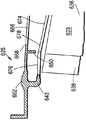
本発明の第3実施例を図6に示す。多くの特徴が、図5に示す実施例における特徴と対応しており、適切である場合には、同じ参照番号を使用した。
この実施例では、上流鍛造部662が、図5の実施例におけるよりも幾分大きく後方に延びている。環状フェンス690が、上流鍛造部662から半径方向内方に延びている。ファンブレード623が作動中に外れた場合、ファンブレードは、ほぼ前縁キャップ638の後方部分でフェンス690に当たる。これにより、第1に、ブレード623の本体636からの前縁キャップ638の分離を促し、第2に、前縁キャップ638を前方に偏向させて(曲げて)ファンケースフック643と係合させる。従って、フェンス690を設けることにより、上文中に更に詳細に説明した所望のブレード破壊挙動を促進し、ブレードの本体636が壊れて小片になると同時に、前縁キャップ638は実質的に無傷のままであり、ファンケース625によって捕捉される。
A third embodiment of the present invention is shown in FIG. Many features correspond to those in the embodiment shown in FIG. 5, and the same reference numerals have been used where appropriate.
In this embodiment, the upstream forging 662 extends somewhat rearward than in the embodiment of FIG. An annular fence 690 extends radially inward from the upstream forged
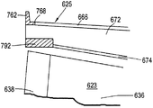
図7は、本発明の第4の変形例を示す。この実施例でも、多くの特徴が、図5に示す実施例における特徴と対応しており、適切である場合には、同じ参照番号を使用した。
この実施例では、図5及び図6の比較的弱い前方部分676の代わりに、環状音響パネル792を使用する。隔壁674及び音響パネル792が互いにファントラックを形成する。これは、従来の方法で隔壁支持構造672に取り付けられる。図5の実施例におけるのと同様に、隔壁支持構造672の前方部分(音響パネル792の半径方向外方の部分)が、隔壁支持構造672の残りの部分よりも弱いように構成されていてもよい。作動中にファンブレード623が外れた場合、ブレードの本体636が隔壁674に当たる。ブレード破壊機構は図5の実施例で説明したのと全く同じである。前縁キャップ638は音響ライナ792に当たる。音響ライナ792の機械的特性は、前縁キャップのエネルギを所望の通りに多かれ少なかれ吸収するように構成されており、そのため、前縁キャップ638は、全体が音響ライナ792内に捕捉されてもよいし、音響ライナ792を通して前方及び外方に案内されるだけであってもよく、その後、ファンケーシング625内に捕捉される。
FIG. 7 shows a fourth modification of the present invention. In this example, many features correspond to those in the example shown in FIG. 5, and the same reference numerals have been used where appropriate.
In this embodiment, an annular
この実施例の上流鍛造部762は、他の実施例の上流鍛造部よりも設計が簡単である。といのは、他の図に示すファンケースフックが設けられていないからである。
本発明のこの実施例の利点は、音響パネル792がファンブレード623の上流部分の周囲に設けられており、並びに音響パネル680がファンブレード623の後方に設けられているため、使用時のエンジンの騒音レベルが低下するということである。
The upstream forged
The advantage of this embodiment of the present invention is that the
本発明の別の利点は、上文中に説明した全ての実施例において、ファンケーシング625が、全体として軽量であり且つ設計が簡単であるということである。これは、外れたファンブレード全体を捕捉する必要がなく、前縁キャップ(又は、金属製中空ブレードの場合には中実の前縁領域)だけを捕捉すればよいためである。詳細には、外ケーシング666を従来の構成におけるよりもかなり薄く形成できる。更に、図7の実施例では、音響ライナ792は、外れた前縁キャップ638のエネルギの幾分か又は全部を吸収するように構成でき、そのため、ファンケーシング625についての捕捉要件を更に減らすことができる。
Another advantage of the present invention is that, in all the embodiments described above, the
ファンケーシングが簡単であり且つ軽量であるため、その製造に様々な(及び安価な)製造方法を使用できる。例えば、図4及び図5の実施例では、先ず最初に隔壁支持構造を発泡体(フォーム)又はハニカムで製造でき、次いで、外ケーシング、隔壁、及び音響ライナをこれに取り付け、その後、研磨性コーティングを付ける。別の実施例では、製造プロセスを外ケーシングから始め、他の構成要素をその中に組み込んでファンケーシングを形成する。 Because the fan casing is simple and lightweight, various (and inexpensive) manufacturing methods can be used to manufacture it. For example, in the embodiment of FIGS. 4 and 5, the partition support structure can first be made of foam or honeycomb, then the outer casing, partition and acoustic liner are attached to it, and then the abrasive coating Add. In another embodiment, the manufacturing process begins with an outer casing and other components are incorporated therein to form a fan casing.
本発明の実施例を複合ファンブレードを参照して概略に説明した。しかしながら、本発明は、外れたブレードのエネルギが比較的小さく、従って、外れたブレードがファンケーシングの氷衝突領域を貫通するのが困難な、即ちライナの見掛強度が高い、任意のファンブレード設計に等しく適用できるということは理解されよう。 Embodiments of the present invention have been described generally with reference to a composite fan blade. However, the present invention provides for any fan blade design in which the energy of the detached blade is relatively small and therefore it is difficult for the detached blade to penetrate the ice impingement region of the fan casing, i.e., the apparent strength of the liner is high. It will be understood that it is equally applicable.
これは、例えば、中実構造の小型ファンブレードの場合である。
本発明は、ファンブレードの前縁がブレードのその他の領域よりもかなり剛性であり且つ強い場合にも利点を提供する。これには、金属製ブレード、発泡体からなるブレード、又は他の構造材料製のブレードが含まれ、これらブレードでは、前縁の特性が当該ブレードの本体の特性と異なっており、また、バードストライク、雹、及び腐蝕等の脅威に対するブレードの保護を高めるために、別体の前縁キャップが設けられる、複合材料(例えばカーボンファイバ又はガラスファイバ)製のブレードが含まれる。しかし、これらのブレードに限定されるものではない。
This is the case, for example, for a solid fan blade.
The present invention also provides an advantage when the leading edge of the fan blade is significantly stiffer and stronger than the other areas of the blade. This includes metal blades, blades made of foam, or blades made of other structural materials, where the leading edge characteristics are different from those of the blade body, and the bird strike Included are blades made of composite material (eg, carbon fiber or glass fiber) that are provided with a separate leading edge cap to enhance the blade's protection against threats such as erosion, erosion and corrosion. However, it is not limited to these blades.
本明細書中に説明した実施例に対し、様々な変更を行うことができるということは理解されよう。例えば、ファンケースフックは、本発明の任意の実施例に設けられていてもよいし、なくてもよい。ファンケースフックが設けられている場合には、ファンケースフックは、ファンケーシングに局所的剛性を追加する傾向がある。 It will be understood that various modifications can be made to the embodiments described herein. For example, the fan case hook may or may not be provided in any embodiment of the present invention. If a fan case hook is provided, the fan case hook tends to add local stiffness to the fan casing.
本発明は、従って、ファンブレードが変形し壊れる態様に合わせて更に正確に調整した捕捉構造を提供し、その設計は、捕捉する必要があるファンブレードのこれらの部分だけを捕捉する機構を提供することによって最適化される。 The present invention thus provides a capture structure that is more precisely tailored to the manner in which the fan blade deforms and breaks, and its design provides a mechanism to capture only those portions of the fan blade that need to be captured. Is optimized by
10 ガスタービンエンジン
11 インテーク
12 ファン
13 中圧コンプレッサ
14 高圧コンプレッサ
15 燃焼器
16 高圧タービン
17 中圧タービン
18 低圧タービン
19 排気ノズル
20、21、22 駆動シャフト
23 ファンブレード
24 ファンディスク
25 ファンケーシング
223 スウェプトファンブレード
226 後縁
228 ブレード先端
DESCRIPTION OF
Claims (5)
前記エンジンは、使用時に前記エンジンの軸線を中心として回転する複数のファンブレードを備え、
前記ケーシングは、前記ファンブレードの半径方向外方に環状構造を含み、この環状構造は、前記ファンブレードの上流及び下流の両方で軸線方向に延び、使用時にファンブレードがほぼ半径方向外方に外れて前記ケーシングに当たる可能性があり、
前記ケーシングは、使用時に前記ファンブレードの半径方向外方にあるファントラックを備えた、ファンケーシングにおいて、
外れたブレードのほぼ全てが、前記ファントラックによって偏向させられ、
前記ファントラックは、弱くした領域を含み、使用時に、外れたファンブレードの部分が前記弱くした領域に入り込んで通過し、外れたファンブレードの残りの部分が前記ファントラックによって偏向させられる、ファンケーシング。 A fan casing for a gas turbine engine,
The engine includes a plurality of fan blades that rotate about the axis of the engine when in use,
The casing includes an annular structure radially outward of the fan blade, the annular structure extending axially both upstream and downstream of the fan blade so that the fan blade is disengaged substantially radially outward in use. may that per the casing Te,
In the fan casing, the casing comprising a fan track that is radially outward of the fan blade in use,
Almost all of the detached blades are deflected by the fan track ,
The fan track includes a weakened area, and in use, a portion of a disengaged fan blade enters and passes through the weakened region and a remaining portion of the disengaged fan blade is deflected by the fan track. .
前記弱くした領域は、前記ファンブレードの前縁領域だけに亘って延びる、ファンケーシング。 The fan casing according to claim 1 ,
The fan casing, wherein the weakened area extends only over the front edge area of the fan blade.
前記弱くした領域は、音響ライナを備えている、ファンケーシング。 The fan casing according to claim 1 or 2 ,
The weakened area is a fan casing comprising an acoustic liner.
前記ケーシングの半径方向内面は、研磨性層を備えている、ファンケーシング。 The fan casing according to any one of claims 1 to 3 ,
The fan casing, wherein a radially inner surface of the casing includes an abrasive layer.
前記研磨性層は、前記ファントラックの軸線方向全長に亘って延びる、ファンケーシング。 The fan casing according to claim 4 ,
The fan casing, wherein the abrasive layer extends over the entire axial length of the fan track.
Applications Claiming Priority (2)
| Application Number | Priority Date | Filing Date | Title |
|---|---|---|---|
| GBGB0813821.6A GB0813821D0 (en) | 2008-07-29 | 2008-07-29 | A fan casing for a gas turbine engine |
| GB0813821.6 | 2008-07-29 |
Publications (3)
| Publication Number | Publication Date |
|---|---|
| JP2010031870A JP2010031870A (en) | 2010-02-12 |
| JP2010031870A5 JP2010031870A5 (en) | 2012-09-13 |
| JP5584440B2 true JP5584440B2 (en) | 2014-09-03 |
Family
ID=39747090
Family Applications (1)
| Application Number | Title | Priority Date | Filing Date |
|---|---|---|---|
| JP2009176036A Expired - Fee Related JP5584440B2 (en) | 2008-07-29 | 2009-07-29 | Fan casing for gas turbine engine |
Country Status (4)
| Country | Link |
|---|---|
| US (1) | US8297912B2 (en) |
| EP (1) | EP2149680B1 (en) |
| JP (1) | JP5584440B2 (en) |
| GB (1) | GB0813821D0 (en) |
Families Citing this family (25)
| Publication number | Priority date | Publication date | Assignee | Title |
|---|---|---|---|---|
| FR2925118B1 (en) * | 2007-12-14 | 2009-12-25 | Snecma | ABRADABLE SUPPORT PANEL IN A TURBOMACHINE |
| GB0916823D0 (en) * | 2009-09-25 | 2009-11-04 | Rolls Royce Plc | Containment casing for an aero engine |
| GB0917149D0 (en) * | 2009-10-01 | 2009-11-11 | Rolls Royce Plc | Impactor containment |
| GB201103682D0 (en) * | 2011-03-04 | 2011-04-20 | Rolls Royce Plc | A turbomachine casing assembly |
| JP5804808B2 (en) | 2011-07-07 | 2015-11-04 | 三菱日立パワーシステムズ株式会社 | Gas turbine combustor and its combustion vibration damping method |
| GB201120105D0 (en) | 2011-11-22 | 2012-01-04 | Rolls Royce Plc | A turbomachine casing assembly |
| EP2620653B1 (en) * | 2012-01-25 | 2015-06-24 | Rolls-Royce plc | A turbomachine casing assembly with blade containment cavity |
| US9534505B2 (en) * | 2012-07-23 | 2017-01-03 | United Technologies Corporation | Integrated nacelle inlet and metallic fan containment case |
| GB201302493D0 (en) | 2013-02-13 | 2013-03-27 | Rolls Royce Plc | A Fan Containment System |
| US10024191B2 (en) * | 2013-03-11 | 2018-07-17 | Rolls-Royce Corporation | Fan track liner designed to yield next to fan case hook |
| EP2971691B1 (en) | 2013-03-13 | 2019-05-08 | United Technologies Corporation | A gas turbine liner for a fan case comprising a torque stop |
| US9789536B2 (en) | 2015-01-20 | 2017-10-17 | United Technologies Corporation | Dual investment technique for solid mold casting of reticulated metal foams |
| US9737930B2 (en) | 2015-01-20 | 2017-08-22 | United Technologies Corporation | Dual investment shelled solid mold casting of reticulated metal foams |
| US9789534B2 (en) | 2015-01-20 | 2017-10-17 | United Technologies Corporation | Investment technique for solid mold casting of reticulated metal foams |
| US9884363B2 (en) | 2015-06-30 | 2018-02-06 | United Technologies Corporation | Variable diameter investment casting mold for casting of reticulated metal foams |
| US9731342B2 (en) | 2015-07-07 | 2017-08-15 | United Technologies Corporation | Chill plate for equiax casting solidification control for solid mold casting of reticulated metal foams |
| US10830136B2 (en) | 2015-11-19 | 2020-11-10 | General Electric Company | Fan case for use in a turbofan engine, and method of assembling a turbofan engine |
| US10563537B2 (en) * | 2016-02-05 | 2020-02-18 | United Technologies Corporation | Energy absorbing beam and sandwich panel structure |
| US10634002B2 (en) * | 2016-05-25 | 2020-04-28 | Rolls-Royce Corporation | Soft wall containment system for gas turbine engine |
| US10487684B2 (en) | 2017-03-31 | 2019-11-26 | The Boeing Company | Gas turbine engine fan blade containment systems |
| US10550718B2 (en) | 2017-03-31 | 2020-02-04 | The Boeing Company | Gas turbine engine fan blade containment systems |
| US10677261B2 (en) * | 2017-04-13 | 2020-06-09 | General Electric Company | Turbine engine and containment assembly for use in a turbine engine |
| GB201816989D0 (en) * | 2018-10-18 | 2018-12-05 | Rolls Royce Plc | Debris retention |
| US11530622B2 (en) * | 2020-10-16 | 2022-12-20 | Pratt & Whitney Canada Corp. | Blade containment assembly for a gas turbine engine |
| US20230193827A1 (en) * | 2021-12-21 | 2023-06-22 | Rolls-Royce Deutschland Ltd & Co Kg | Fan case assembly for a gas turbine engine |
Family Cites Families (11)
| Publication number | Priority date | Publication date | Assignee | Title |
|---|---|---|---|---|
| FR2574476B1 (en) * | 1984-12-06 | 1987-01-02 | Snecma | RETENTION HOUSING FOR TURBOJET BLOWER |
| US5823739A (en) * | 1996-07-03 | 1998-10-20 | United Technologies Corporation | Containment case for a turbine engine |
| US6290455B1 (en) * | 1999-12-03 | 2001-09-18 | General Electric Company | Contoured hardwall containment |
| US6227794B1 (en) * | 1999-12-16 | 2001-05-08 | Pratt & Whitney Canada Corp. | Fan case with flexible conical ring |
| GB2361032A (en) | 2000-04-05 | 2001-10-10 | Rolls Royce Plc | A gas turbine engine blade containment assembly |
| FR2832191B1 (en) * | 2001-11-14 | 2004-10-08 | Snecma Moteurs | FRAGILE TOP SUMMER BLOWER |
| US6619913B2 (en) * | 2002-02-15 | 2003-09-16 | General Electric Company | Fan casing acoustic treatment |
| GB2416192B (en) | 2004-07-14 | 2006-09-27 | Rolls Royce Plc | Ducted fan with containment structure |
| GB0501284D0 (en) | 2005-01-21 | 2005-03-02 | Rolls Royce Plc | Aerofoil containment structure |
| GB2426287B (en) | 2005-05-18 | 2007-05-30 | Rolls Royce Plc | Blade containment structure |
| GB0609632D0 (en) * | 2006-05-16 | 2006-06-28 | Rolls Royce Plc | An ice impact panel |
-
2008
- 2008-07-29 GB GBGB0813821.6A patent/GB0813821D0/en not_active Ceased
-
2009
- 2009-06-17 EP EP09251579.0A patent/EP2149680B1/en not_active Not-in-force
- 2009-06-19 US US12/457,748 patent/US8297912B2/en active Active
- 2009-07-29 JP JP2009176036A patent/JP5584440B2/en not_active Expired - Fee Related
Also Published As
| Publication number | Publication date |
|---|---|
| EP2149680A2 (en) | 2010-02-03 |
| US20100028130A1 (en) | 2010-02-04 |
| GB0813821D0 (en) | 2008-09-03 |
| EP2149680B1 (en) | 2018-12-26 |
| US8297912B2 (en) | 2012-10-30 |
| JP2010031870A (en) | 2010-02-12 |
| EP2149680A3 (en) | 2017-08-16 |
Similar Documents
| Publication | Publication Date | Title |
|---|---|---|
| JP5584440B2 (en) | Fan casing for gas turbine engine | |
| JP2010031871A (en) | Fan casing for gas turbine engine | |
| EP1149229B1 (en) | Hardwall fan case with structured bumper | |
| EP1240412B1 (en) | Fan case with flexible conical ring | |
| US9677570B2 (en) | Gas turbine engine | |
| JP3789129B2 (en) | Fan blade assembly | |
| US9683490B2 (en) | Pivoting fan track liner for blade retainment | |
| JP4719349B2 (en) | Fan case for a turbofan engine having a turbofan engine and a fan decoupler | |
| EP0965731A2 (en) | A gas turbine containment casing | |
| US10337350B2 (en) | Gas turbine engine | |
| JP2001200798A (en) | Contoured hardwall containment | |
| CN110685957A (en) | Blade containing structure | |
| US9835046B2 (en) | Gas turbine engine | |
| JP2008163946A (en) | Method and apparatus for fabricating fan assembly for use with turbine engine | |
| US10294794B2 (en) | Gas turbine engine | |
| EP2944771B1 (en) | Fan containment system of a gas turbine engine | |
| GB2523069A (en) | Gas turbine engine | |
| US20230243275A1 (en) | Composite fan case containment hook and improved forward debris capture | |
| GB2545909A (en) | Fan disk and gas turbine engine |
Legal Events
| Date | Code | Title | Description |
|---|---|---|---|
| A524 | Written submission of copy of amendment under section 19 (pct) |
Free format text: JAPANESE INTERMEDIATE CODE: A524 Effective date: 20120726 |
|
| A621 | Written request for application examination |
Free format text: JAPANESE INTERMEDIATE CODE: A621 Effective date: 20120726 |
|
| A977 | Report on retrieval |
Free format text: JAPANESE INTERMEDIATE CODE: A971007 Effective date: 20131126 |
|
| A131 | Notification of reasons for refusal |
Free format text: JAPANESE INTERMEDIATE CODE: A131 Effective date: 20131128 |
|
| A601 | Written request for extension of time |
Free format text: JAPANESE INTERMEDIATE CODE: A601 Effective date: 20140224 |
|
| A602 | Written permission of extension of time |
Free format text: JAPANESE INTERMEDIATE CODE: A602 Effective date: 20140227 |
|
| A521 | Written amendment |
Free format text: JAPANESE INTERMEDIATE CODE: A523 Effective date: 20140526 |
|
| TRDD | Decision of grant or rejection written | ||
| A01 | Written decision to grant a patent or to grant a registration (utility model) |
Free format text: JAPANESE INTERMEDIATE CODE: A01 Effective date: 20140619 |
|
| A61 | First payment of annual fees (during grant procedure) |
Free format text: JAPANESE INTERMEDIATE CODE: A61 Effective date: 20140718 |
|
| R150 | Certificate of patent or registration of utility model |
Ref document number: 5584440 Country of ref document: JP Free format text: JAPANESE INTERMEDIATE CODE: R150 |
|
| R250 | Receipt of annual fees |
Free format text: JAPANESE INTERMEDIATE CODE: R250 |
|
| R250 | Receipt of annual fees |
Free format text: JAPANESE INTERMEDIATE CODE: R250 |
|
| R250 | Receipt of annual fees |
Free format text: JAPANESE INTERMEDIATE CODE: R250 |
|
| LAPS | Cancellation because of no payment of annual fees |