JP5583625B2 - Multi-stage transmission assembly and disassembly jig - Google Patents

Multi-stage transmission assembly and disassembly jig Download PDF

Info

Publication number
JP5583625B2
JP5583625B2 JP2011078739A JP2011078739A JP5583625B2 JP 5583625 B2 JP5583625 B2 JP 5583625B2 JP 2011078739 A JP2011078739 A JP 2011078739A JP 2011078739 A JP2011078739 A JP 2011078739A JP 5583625 B2 JP5583625 B2 JP 5583625B2
Authority
JP
Japan
Prior art keywords
gear shaft
gear
rod
holder
counter
Prior art date
Legal status (The legal status is an assumption and is not a legal conclusion. Google has not performed a legal analysis and makes no representation as to the accuracy of the status listed.)
Active
Application number
JP2011078739A
Other languages
Japanese (ja)
Other versions
JP2012211681A (en
Inventor
真也 松本
貴志 工藤
浩二 上中別府
Current Assignee (The listed assignees may be inaccurate. Google has not performed a legal analysis and makes no representation or warranty as to the accuracy of the list.)
Honda Motor Co Ltd
Original Assignee
Honda Motor Co Ltd
Priority date (The priority date is an assumption and is not a legal conclusion. Google has not performed a legal analysis and makes no representation as to the accuracy of the date listed.)
Filing date
Publication date
Application filed by Honda Motor Co Ltd filed Critical Honda Motor Co Ltd
Priority to JP2011078739A priority Critical patent/JP5583625B2/en
Publication of JP2012211681A publication Critical patent/JP2012211681A/en
Application granted granted Critical
Publication of JP5583625B2 publication Critical patent/JP5583625B2/en
Active legal-status Critical Current
Anticipated expiration legal-status Critical

Links

Images

Description

本発明は、常時噛合い式の多段変速機の組立及び分解用治具に関する。   The present invention relates to a jig for assembling and disassembling a constantly meshing multi-stage transmission.

互いに平行な歯車軸11,12にそれぞれ複数の駆動歯車mと被動歯車nが変速段毎に常時噛み合い状態で軸支され、駆動歯車mと被動歯車nの一方の複数の歯車mが歯車軸11に固定され、他方の複数の歯車nと歯車軸12との間で歯車軸12と各歯車nの係合を揺動爪部材Rの揺動によって歯車ごとに切り換える係合切換機構20が備えられ、変速駆動機構50のコントロールロッド51が歯車軸12の内部を軸方向に移動することにより係合切換機構20の揺動爪部材Rが揺動されて変速を行う多段変速機10について、本願と同じ出願人により先に出願した例がある(特許文献1参照)。 A plurality of drive gears m and driven gears n are respectively supported by gear shafts 11 and 12 parallel to each other in a constantly meshed state for each shift stage, and one of the plurality of gears m of the drive gear m and the driven gear n is connected to the gear shaft 11. And an engagement switching mechanism 20 that switches the engagement of the gear shaft 12 and each gear n between the other plurality of gears n and the gear shaft 12 for each gear by the swinging of the swinging claw member R. The multi-stage transmission 10 in which the control rod 51 of the speed change drive mechanism 50 moves in the axial direction within the gear shaft 12 and the swinging claw member R of the engagement switching mechanism 20 is swung to shift the speed. There is an example of an earlier application by the same applicant (see Patent Document 1).

特開2010−078048号公報JP 2010-078048 A

歯車軸12に揺動爪部材Rなどの係合切換機構20を組み込み、その周囲に各歯車nを軸支しなければならないが、特許文献1では、特別治具を用いずに組立および分解を行っていた。   An engagement switching mechanism 20 such as a rocking claw member R must be incorporated in the gear shaft 12 and each gear n must be pivotally supported around the gear shaft 12, but in Patent Document 1, assembly and disassembly are not performed without using a special jig. I was going.

したがって、組立に際しては、1速段ごとに、歯車軸12に揺動爪部材Rなどの係合切換機構20を組み込み、1つの歯車nを嵌合する作業を、繰り返しながら順次組み立てており、分解するときも同様で、1速段ごとに、歯車軸12から1つの歯車nを抜き取り、係合切換機構20を外す作業を、繰り返しながら順次分解していた。
そのため、組立も分解も極めて煩雑な作業となり、作業に時間と労力を要した。
Therefore, when assembling, the engagement switching mechanism 20 such as the swinging claw member R is incorporated in the gear shaft 12 at every first gear stage, and the operation of fitting one gear n is sequentially repeated and assembled. In the same manner, the operation of pulling out one gear n from the gear shaft 12 and removing the engagement switching mechanism 20 for each first gear is sequentially disassembled while being repeated.
For this reason, assembly and disassembly are extremely complicated operations, which require time and labor.

本発明は、かかる点に鑑みなされたもので、その目的とする処は、多段変速機の組立および分解作業を容易にする治具を供する点にある。   The present invention has been made in view of the above points, and the object of the present invention is to provide a jig that facilitates assembly and disassembly of the multi-stage transmission.

上記目的を達成するために、請求項1記載の発明は、
第1歯車(m)群を回転不能に軸支する第1歯車軸(11)と、
前記第1歯車軸(11)に平行に設けられ前記第1歯車(m)群と常時噛合う第2歯車(n)群を回転自在に軸支するとともに軸中心に中空部を有する第2歯車軸(12)と、
前記第2歯車軸(12)に揺動自在に支持されスプリング(22)により付勢されて前記第2歯車軸(12)の外周面より係合爪部(Rp)を突出して前記第2歯車(n)群の内周面に形成された係合凸部(31)に係合して前記第2歯車軸(12)と前記第2歯車(n)群を一体に回転させる揺動爪部材(R)と、
前記第2歯車軸(12)の軸中心側から外周に向かって進退自在に設けられ前記揺動爪部材(R)の前記係合爪部(Rp)を前記第2歯車軸(12)の外周面から内側に押し戻すピン部材(23)と、
前記第2歯車軸(12)の中空部に軸方向に摺動自在に設けられ前記ピン部材(23)を進退させるカム溝を有するカムロッド(C)と、
前記カムロッド(C)を軸方向に移動させるコントロールロッド(51)と、
を備えた多段変速機の組立及び分解用治具において、
前記カムロッド(C)と前記コントロールロッド(51)の代わりに前記第2歯車軸(12)の中空部に挿入されて全ての前記ピン部材(23)を前記第2歯車軸(12)の外周方向に押し出し全ての前記揺動爪部材(R)の前記係合爪部(Rp)を前記第2歯車軸(12)の外周面から内側に押し戻して全ての前記第2歯車(n)群と前記揺動爪部材(R)の係合を解除状態とするカウンタロッド(85)と、
前記第2歯車軸(12)の外周面に嵌合されるとともに前記揺動爪部材(R)の前記係合爪部(Rp)が前記第2歯車軸(12)の外周面より突出した際に前記係合爪部(Rp)が進入可能な孔部(90h)を設けたアウタカラー(90)と、
を備えたことを特徴とする多段変速機の組立及び分解用治具である。
In order to achieve the above object, the invention according to claim 1
A first gear shaft (11) that rotatably supports the first gear (m) group;
A second gear which is provided in parallel to the first gear shaft (11) and rotatably supports a second gear (n) group which always meshes with the first gear (m) group and has a hollow portion at the shaft center. The axis (12),
The second gear shaft (12) is supported in a swingable manner and is urged by a spring (22) so that the engaging claw portion (Rp) protrudes from the outer peripheral surface of the second gear shaft (12). (n) A swinging claw member that engages with an engaging projection (31) formed on the inner peripheral surface of the group and rotates the second gear shaft (12) and the second gear (n) group integrally. (R) and
The engaging claw portion (Rp) of the swinging claw member (R) provided so as to be able to advance and retreat from the axial center side of the second gear shaft (12) to the outer periphery of the second gear shaft (12). A pin member (23) to be pushed back inward from the surface,
A cam rod (C) provided in a hollow portion of the second gear shaft (12) so as to be slidable in the axial direction and having a cam groove for moving the pin member (23) forward and backward;
A control rod (51) for moving the cam rod (C) in the axial direction;
In the assembly and disassembly jig of the multi-stage transmission equipped with
Instead of the cam rod (C) and the control rod (51), the pin member (23) is inserted into the hollow portion of the second gear shaft (12) so that the outer peripheral direction of the second gear shaft (12). The engaging claw portions (Rp) of all the swinging claw members (R) pushed out to the inside from the outer peripheral surface of the second gear shaft (12) are pushed back inwardly to all the second gear (n) groups and the A counter rod (85) for releasing the engagement of the swing claw member (R);
When the engaging claw portion (Rp) of the swing claw member (R) is projected from the outer peripheral surface of the second gear shaft (12) while being fitted to the outer peripheral surface of the second gear shaft (12). An outer collar (90) provided with a hole (90h) through which the engaging claw portion (Rp) can enter,
A jig for assembling and disassembling a multi-stage transmission, comprising:

請求項2記載の発明は、請求項1記載の多段変速機の組立及び分解用治具において、
円錐筒状の周壁(91a)の小径の端部に中空の底壁(91b)が形成され前記第2歯車軸(12)に軸支される前記第2歯車(n)群を囲繞するギアホルダ(91)と、
前記ギアホルダ(91)の内部に前記第2歯車(n)群を収容して前記ギアホルダ(91)の大径の開口端に係止して蓋をする蓋部材(92)とを設けたことを特徴とする。
The invention according to claim 2 is the assembly and disassembly jig for the multi-stage transmission according to claim 1,
A hollow bottom wall (91b) is formed at the small diameter end of the conical cylindrical peripheral wall (91a), and a gear holder surrounds the second gear (n) group supported by the second gear shaft (12). 91) and
A lid member (92) for accommodating the second gear (n) group inside the gear holder (91) and locking the lid to a large-diameter opening end of the gear holder (91); Features.

請求項3記載の発明は、請求項1または請求項2記載の多段変速機の組立及び分解用治具において、
前記カムロッド(C)を前記コントロールロッド(51)に組付けた状態で周囲を囲繞するシフトロッドホルダ(82)を設けたことを特徴とする。
The invention according to claim 3 is a jig for assembling and disassembling the multi-stage transmission according to claim 1 or 2,
A shift rod holder ( 82 ) surrounding the periphery in a state where the cam rod (C) is assembled to the control rod (51) is provided.

請求項4記載の発明は、請求項2記載の多段変速機の組立及び分解用治具において、
前記第2歯車軸(12)と同じ外径を有した円筒本体(87a)を有し、前記円筒本体の外周に前記アウタカラー(90)をセットするとともに、前記円筒本体(87a)の端部内周に前記カウンタロッド(85)の端部を保持する鍔部(87c)を有した第1ホルダベース(87)を設けたことを特徴とする。
The invention according to claim 4 is a jig for assembling and disassembling the multi-stage transmission according to claim 2,
A cylindrical main body (87a) having the same outer diameter as the second gear shaft (12); the outer collar (90) is set on the outer periphery of the cylindrical main body; and the inner end of the cylindrical main body (87a) A first holder base (87) having a flange (87c) for holding the end of the counter rod (85) is provided on the periphery.

請求項5記載の発明は、請求項1ないし請求項4のいずれか1項記載の多段変速機の組立及び分解用治具において、
前記第2歯車軸(12)の外周に嵌合する円筒本体(100a)を有し、前記円筒本体(100a)の一開口端に前記揺動爪部材(R)の1個分が露出する開口部(100c)が切り欠かれたラチェットセットホルダ(100)を設けたことを特徴とする。
The invention according to claim 5 is a jig for assembling and disassembling a multi-stage transmission according to any one of claims 1 to 4,
An opening having a cylindrical main body (100a) fitted to the outer periphery of the second gear shaft (12) and exposing one of the swinging claw members (R) at one opening end of the cylindrical main body (100a). A ratchet set holder (100) in which a portion (100c) is cut out is provided.

請求項1記載の多段変速機の組立及び分解用治具によれば、カウンタロッド(85)が、カムロッド(C)とコントロールロッド(51)の代わりに第2歯車軸(12)の中空部に挿入されると、第2歯車軸(12)に組み込まれた全ての揺動爪部材(R)が係合爪部(Rp)を外周面から引込めた状態に維持することができるので、全ての第2歯車(n)群を一斉に組み込みまたは取り外しすることを可能とし、また、アウタカラー(90)は、第2歯車軸(12)に組み込まれた揺動爪部材(R)が外周面より突出した係合爪部(Rp)を孔部に進入させて係止させて第2歯車軸(12)の外周面に嵌合することができ、カウンタロッド(85)と組み合わせて使用して、第2歯車軸(12)に対して第2歯車(n)群と交代して組み込みまたは取り外しすることができ、多段変速機の組立および分解作業を容易にすることができる。   According to the assembly and disassembly jig of the multi-stage transmission according to claim 1, the counter rod (85) is placed in the hollow portion of the second gear shaft (12) instead of the cam rod (C) and the control rod (51). When inserted, all the swinging claw members (R) built into the second gear shaft (12) can keep the engaging claw part (Rp) retracted from the outer peripheral surface. The second gear (n) group can be assembled or removed all at once, and the outer collar (90) has a rocking claw member (R) incorporated in the second gear shaft (12) on the outer peripheral surface. The more protruding engagement claw (Rp) can be inserted into the hole and locked to fit the outer peripheral surface of the second gear shaft (12), and used in combination with the counter rod (85) The second gear shaft (12) can be installed or removed in place of the second gear (n) group to facilitate the assembly and disassembly of the multi-stage transmission. It can be.

請求項2記載の多段変速機の組立及び分解用治具によれば、円錐筒状の周壁(91a)の小径の端部に中空の底壁(91b)が形成されたギアホルダ(91)が、内部に第2歯車(n)群を収容して大径の開口端を蓋部材(92)で蓋をすることができるので、第2歯車(n)群を一体で取り扱い、第2歯車軸(12)に取り付けおよび取り外しを簡単にし、多段変速機の組立および分解作業を容易にする。   According to the jig for assembling and disassembling the multi-stage transmission according to claim 2, the gear holder (91) in which the hollow bottom wall (91b) is formed at the small diameter end of the conical cylindrical peripheral wall (91a), Since the second gear (n) group can be accommodated inside and the large-diameter opening end can be covered with the lid member (92), the second gear (n) group can be handled integrally and the second gear shaft ( 12) Simplifies installation and removal, and facilitates assembly and disassembly work of multi-stage transmission.

請求項3記載の多段変速機の組立及び分解用治具によれば、シフトロッドホルダ(82)がカムロッド(C)をコントロールロッド(51)に組付けた状態で周囲を囲繞することができるので、コントロールロッド(51)にカムロッド(C)が結合された状態で取り扱うことができ、第2歯車軸(12)の中空部に挿入および抜き出し等を容易にし、組立分解の作業性を良好にする。 According to the assembly and disassembly jig for the multi-stage transmission according to claim 3, the shift rod holder ( 82 ) can surround the cam rod (C) with the control rod (51) attached to the periphery. , Can be handled with the cam rod (C) connected to the control rod (51), and can be easily inserted into and removed from the hollow portion of the second gear shaft (12) to improve assembly / disassembly workability. .

請求項4記載の多段変速機の組立及び分解用治具によれば、第1ホルダベース(87)がアウタカラー(90)を円筒本体(87a)の外周にセットし、円筒本体(87a)の端部内周の鍔部(87c)がカウンタロッド(85)の端部を保持するので、第1ホルダベース(87)が端部を保持したカウンタロッド(85)を第2歯車軸(12)の中空部に挿入して円筒本体(87a)を第2歯車軸(12)に同軸に当接することで、第2歯車軸(12)に軸支された第2歯車(n)群と円筒本体(87a)の外周にセットされたアウタカラー(90)の入れ替えを簡単に行うことができる。   According to the assembly and disassembly jig for the multi-stage transmission according to claim 4, the first holder base (87) sets the outer collar (90) on the outer periphery of the cylindrical body (87a), and the cylindrical body (87a) Since the flange portion (87c) on the inner periphery of the end portion holds the end portion of the counter rod (85), the counter rod (85) held by the first holder base (87) is attached to the second gear shaft (12). By inserting the cylindrical body (87a) coaxially with the second gear shaft (12) after being inserted into the hollow portion, the second gear (n) group supported on the second gear shaft (12) and the cylindrical body ( The outer collar (90) set on the outer periphery of 87a) can be easily replaced.

請求項5記載の多段変速機の組立及び分解用治具によれば、ラチェットセットホルダ(100)を第2歯車軸(12)の外周に嵌合して第2歯車軸(12)の外周面の揺動爪部材(R)を取り付けようとする位置に開口部(100c)を合せ、開口部(100c)から第2歯車軸(12)に揺動爪部材(R)を取り付け、ラチェットセットホルダ(100)を回動または軸方向に移動して次の揺動爪部材(R)の取り付けを順次行うことで、既に取り付けた揺動爪部材(R)を円筒本体が押さえて保持することができ、揺動爪部材(R)の第2歯車軸(12)への組付作業を容易にし円滑に速やかに作業を行うことができる。   According to the jig for assembly and disassembly of the multi-stage transmission according to claim 5, the ratchet set holder (100) is fitted to the outer periphery of the second gear shaft (12), and the outer peripheral surface of the second gear shaft (12). Align the opening (100c) with the position where the swinging claw member (R) is to be attached, and attach the swinging claw member (R) from the opening (100c) to the second gear shaft (12). (100) can be rotated or moved in the axial direction, and the next swinging claw member (R) can be attached in sequence, so that the already installed swinging claw member (R) can be held by the cylindrical body. It is possible to facilitate the assembly work of the swinging claw member (R) to the second gear shaft (12), and to perform the work smoothly and promptly.

本発明の一実施の形態に係る多段変速機の断面図である。It is sectional drawing of the multistage transmission which concerns on one embodiment of this invention. カウンタ歯車軸およびその周りの構造を示す断面図(図4,図5のII−II線断面図)である。It is sectional drawing (II-II sectional view taken on the line of FIG. 4, FIG. 5) which shows a counter gear shaft and the structure around it. カウンタ歯車軸およびその周りの構造を示す別の断面図(図4,図5のIII−III線断面図)である。It is another sectional view (III-III line sectional view of Drawing 4 and Drawing 5) which shows a counter gear shaft and the structure around it. 図2,図3のIV−IV線断面図である。FIG. 4 is a sectional view taken along line IV-IV in FIGS. 2 and 3. 図2,図3のV−V線断面図である。FIG. 5 is a cross-sectional view taken along line VV in FIGS. 2 and 3. コントロールロッドとロストモーション機構の分解斜視図である。It is a disassembled perspective view of a control rod and a lost motion mechanism. コントロールロッドにロストモーション機構組み付けた状態とカムロッド等の分解斜視図である。FIG. 5 is an exploded perspective view of a state in which a lost motion mechanism is assembled to a control rod and a cam rod and the like. カウンタ歯車軸およびピン部材とスプリングの一部の分解斜視図である。It is a disassembled perspective view of a part of a counter gear shaft, a pin member, and a spring. カウンタ歯車軸の左側面図(図8のIX矢視図)である。FIG. 9 is a left side view of the counter gear shaft (a view taken along arrow IX in FIG. 8). 揺動爪部材および支軸ピン,ピン部材,スプリングの分解斜視図である。It is a disassembled perspective view of a rocking claw member, a spindle pin, a pin member, and a spring. コントロールロッドに変速駆動手段の一部および係合手段を組み付けた状態を示す斜視図である。It is a perspective view which shows the state which assembled | attached a part of speed-change drive means and the engagement means to the control rod. 図11に示す状態のカウンタ歯車軸に1つの軸受カラー部材を外装した状態を示す斜視図である。FIG. 12 is a perspective view showing a state in which one bearing collar member is packaged on the counter gear shaft in the state shown in FIG. 11. 2速へのシフトアップ完了直前のカウンタ歯車軸およびその周りの構造を示す断面図である。It is sectional drawing which shows the counter gear shaft just before completion of the upshift to the 2nd speed and the structure around it. 図13のXIV−XIV線断面図である。It is the XIV-XIV sectional view taken on the line of FIG. 図13のXV−XV線断面図である。It is the XV-XV sectional view taken on the line of FIG. 多段変速機の分解手順の初めの分解作業を説明するための図である。It is a figure for demonstrating the disassembly work of the beginning of the disassembly procedure of a multistage transmission. 次の分解作業を説明するための図である。It is a figure for demonstrating the next disassembly work. 次の分解作業を説明するための図である。It is a figure for demonstrating the next disassembly work. 次の分解作業を説明するための図である。It is a figure for demonstrating the next disassembly work. 次の分解作業を説明するための図である。It is a figure for demonstrating the next disassembly work. 次の分解作業を説明するための図である。It is a figure for demonstrating the next disassembly work. 次の分解作業を説明するための図である。It is a figure for demonstrating the next disassembly work. 次の分解作業を説明するための図である。It is a figure for demonstrating the next disassembly work. 次の分解作業を説明するための図である。It is a figure for demonstrating the next disassembly work. 次の分解作業を説明するための図である。It is a figure for demonstrating the next disassembly work. 次の分解作業を説明するための図である。It is a figure for demonstrating the next disassembly work. 次の分解作業を説明するための図である。It is a figure for demonstrating the next disassembly work. 次の分解作業を説明するための図である。It is a figure for demonstrating the next disassembly work. 次の分解作業を説明するための図である。It is a figure for demonstrating the next disassembly work. 多段変速機の組立手順の初めの組立作業を説明するための図である。It is a figure for demonstrating the assembly work of the beginning of the assembly procedure of a multistage transmission. 次の組立作業を説明するための図である。It is a figure for demonstrating the next assembly operation. 次の組立作業を説明するための図である。It is a figure for demonstrating the next assembly operation. 次の組立作業を説明するための図である。It is a figure for demonstrating the next assembly operation. 次の組立作業を説明するための図である。It is a figure for demonstrating the next assembly operation.

以下、本発明に係る一実施の形態について図1ないし図34に基づいて説明する。
まず、本実施の形態に適用される多段変速機10について図1ないし図15に基づいて説明する。
本多段変速機10は、自動二輪車に搭載される内燃機関に組み込まれて構成されている。
Hereinafter, an embodiment according to the present invention will be described with reference to FIGS.
First, a multi-stage transmission 10 applied to the present embodiment will be described with reference to FIGS.
The multi-stage transmission 10 is configured to be incorporated in an internal combustion engine mounted on a motorcycle.

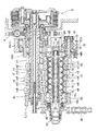
図1は、該多段変速機10の断面図であり、同図1に示すように、該多段変速機10は、内燃機関と共通の機関ケース1に設けられている。
左右割りの左機関ケース1Lと右機関ケース1Rが合体して構成された機関ケース1は、変速室2を形成しており、同変速室2にメイン歯車軸11とカウンタ歯車軸12が互いに平行に左右方向に指向して回転自在に軸支されている。
FIG. 1 is a cross-sectional view of the multi-stage transmission 10. As shown in FIG. 1, the multi-stage transmission 10 is provided in an engine case 1 that is common to an internal combustion engine.
The engine case 1 formed by combining the left engine case 1L and the right engine case 1R which are divided into left and right forms a transmission chamber 2, in which the main gear shaft 11 and the counter gear shaft 12 are parallel to each other. The shaft is supported so as to be rotatable in the left-right direction.

メイン歯車軸11は、左機関ケース1Lの側壁と右機関ケース1Rの別体の側壁1RRにベアリング3L,3Rを介して回転自在に軸支され、右ベアリング3Rを貫通して変速室2から突出した右端部には多板式の摩擦クラッチ5が設けられている。   The main gear shaft 11 is rotatably supported by bearings 3L and 3R on a side wall of the left engine case 1L and a separate side wall 1RR of the right engine case 1R, and protrudes from the transmission chamber 2 through the right bearing 3R. A multi-plate friction clutch 5 is provided at the right end.

摩擦クラッチ5の左側には、図示されないクランク軸の回転が伝達されるプライマリ被動ギヤ4がメイン歯車軸11に回転自在に軸支されている。
内燃機関のクランク軸の回転がプライマリ被動ギヤ4から係合状態の摩擦クラッチ5を介してメイン歯車軸11に伝達される。
On the left side of the friction clutch 5, a primary driven gear 4 to which rotation of a crankshaft (not shown) is transmitted is rotatably supported by the main gear shaft 11.
The rotation of the crankshaft of the internal combustion engine is transmitted from the primary driven gear 4 to the main gear shaft 11 via the engaged friction clutch 5.

他方、カウンタ歯車軸12も、左機関ケース1Lの側壁と右機関ケース1Rの側壁1RRにベアリング7L,7Rを介して回転自在に軸支され、左ベアリング7Lを貫通して変速室2から突出した左端部には出力スプロケット32がスプライン嵌合して袋ナット37で抜け止めされて取り付けられる。   On the other hand, the counter gear shaft 12 is also rotatably supported on the side wall of the left engine case 1L and the side wall 1RR of the right engine case 1R via bearings 7L and 7R, and protrudes from the transmission chamber 2 through the left bearing 7L. An output sprocket 32 is spline-fitted to the left end and is secured by a cap nut 37 and attached.

出力スプロケット32に巻き掛けられた駆動チェーン38が後方の図示されない後輪を駆動するスプロケットに巻き掛けられ、カウンタ歯車軸12の回転動力が後輪に伝達され、車両が走行する。   A drive chain 38 that is wound around the output sprocket 32 is wound around a sprocket that drives a rear wheel (not shown) at the rear, and the rotational power of the counter gear shaft 12 is transmitted to the rear wheel so that the vehicle travels.

メイン歯車軸11には、左右のベアリング3L,3Rの間に駆動変速歯車m群がメイン歯車軸11と一体に回転可能にメイン歯車軸11に構成されている。
右ベアリング3Rに沿って第1駆動変速歯車m1がメイン歯車軸11に一体に形成され、メイン歯車軸11の同第1駆動変速歯車m1と左ベアリング3Lとの間に形成されたスプラインに右から左へ順に順次径を大きくした第2,第3,第4,第5,第6駆動変速歯車m2,m3,m4,m5,m6がスプライン嵌合されている。
On the main gear shaft 11, a drive transmission gear m group is configured between the left and right bearings 3L, 3R so as to be rotatable integrally with the main gear shaft 11.
A first drive transmission gear m1 is formed integrally with the main gear shaft 11 along the right bearing 3R, and a spline formed between the first drive transmission gear m1 of the main gear shaft 11 and the left bearing 3L is viewed from the right. The second, third, fourth, fifth, and sixth drive transmission gears m2, m3, m4, m5, and m6, whose diameters are sequentially increased to the left, are spline-fitted.

他方、カウンタ歯車軸12には、左右のベアリング7L,7Rの間に被動変速歯車n群が円環状の軸受カラー部材13を介して回転自在に軸支されている。
カウンタ歯車軸12において、右ベアリング7Rの左に介装されたワッシャ14Rを介して外装された右端の軸受カラー部材13と、左ベアリング7Lの右に介装されたワッシャ14Lを介して外装された左端の軸受カラー部材13との間に、等間隔に5つの軸受カラー部材13が外装され、この全部で7つの軸受カラー部材13の隣り合う軸受カラー部材13,13間に跨るようにして右から左へ順に順次径を小さくした第1,第2,第3,第4,第5,第6被動変速歯車n1,n2,n3,n4,n5,n6が回転自在に軸支されている。
On the other hand, on the counter gear shaft 12, a group of driven transmission gears n is rotatably supported via an annular bearing collar member 13 between the left and right bearings 7L and 7R.
In the counter gear shaft 12, a right end bearing collar member 13 is provided through a washer 14R interposed on the left side of the right bearing 7R, and is provided through a washer 14L provided on the right side of the left bearing 7L. Between the bearing collar member 13 at the left end, five bearing collar members 13 are externally equidistantly spaced from the right so as to straddle between the adjacent bearing collar members 13, 13 of the seven bearing collar members 13 in total. First, second, third, fourth, fifth, and sixth driven transmission gears n1, n2, n3, n4, n5, and n6, whose diameters are sequentially reduced to the left, are rotatably supported.

メイン歯車軸11と一体に回転する第1,第2,第3,第4,第5,第6駆動変速歯車m1,m2,m3,m4,m5,m6は、カウンタ歯車軸12に回転自在に軸支される対応する第1,第2,第3,第4,第5,第6被動変速歯車n1,n2,n3,n4,n5,n6にそれぞれ常時噛み合っている。   The first, second, third, fourth, fifth, and sixth drive transmission gears m1, m2, m3, m4, m5, and m6 that rotate integrally with the main gear shaft 11 are rotatable on the counter gear shaft 12. The corresponding first, second, third, fourth, fifth and sixth driven transmission gears n1, n2, n3, n4, n5 and n6 are always meshed with each other.

第1駆動変速歯車m1と第1被動変速歯車n1の噛合が、最も減速比の大きい1速を構成し、第6駆動変速歯車m6と第6被動変速歯車n6の噛合が、最も減速比の小さい6速を構成し、その間順次減速比が小さくなって2速、3速、4速、5速が構成される。   The meshing of the first drive transmission gear m1 and the first driven transmission gear n1 constitutes the first speed with the largest reduction ratio, and the meshing of the sixth drive transmission gear m6 and the sixth driven transmission gear n6 has the smallest reduction ratio. Sixth speed is configured, and during that period, the reduction gear ratio is gradually decreased to form second speed, third speed, fourth speed, and fifth speed.

カウンタ歯車軸12に変速段が奇数段の奇数段歯車(第1,第3,第5被動変速歯車n1,n3,n5)と変速段が偶数段の偶数段歯車(第2,第4,第6被動変速歯車n2,n4,n6)が交互に配列されることになる。   The counter gear shaft 12 has odd-numbered gears (first, third, and fifth driven gears n1, n3, and n5) with odd-numbered gears and even-numbered gears (second, fourth, and fourth) with even-numbered gears. 6 driven transmission gears n2, n4, n6) are alternately arranged.

中空筒状をなすカウンタ歯車軸12は、各被動変速歯車nと係合可能な係合手段20が後記するように組み込まれ、後記するように係合手段20の1構成要素である種類ごと2本ずつ4種類の計8本のカムロッドC(Cao,Cao,Cae,Cae,Cbo,Cbo,Cbe,Cbe)がカウンタ歯車軸12の中空内周面に形成された後記するカム案内溝12gに嵌合して軸方向に移動自在に設けられる。   The counter gear shaft 12 having a hollow cylindrical shape is incorporated so that the engagement means 20 that can be engaged with each driven transmission gear n will be described later. A total of eight cam rods C (Cao, Cao, Cae, Cae, Cbo, Cbo, Cbe, Cbe) are formed in the hollow inner peripheral surface of the counter gear shaft 12 and fit into a cam guide groove 12g described later. In addition, they are provided so as to be movable in the axial direction.

このカムロッドCを駆動して変速する変速駆動手段50の1構成要素であるコントロールロッド51が、カウンタ歯車軸12の中空中心軸に挿入されており、コントロールロッド51の軸方向の移動は、ロストモーション機構52,53を介して連動してカムロッドCを軸方向に移動する。   A control rod 51, which is one component of the speed change driving means 50 that drives the cam rod C to change the speed, is inserted into the hollow central axis of the counter gear shaft 12, and the movement of the control rod 51 in the axial direction is lost motion. The cam rod C is moved in the axial direction in conjunction with each other via the mechanisms 52 and 53.

このコントロールロッド51を軸方向に移動する機構が、右機関ケース1Rに設けられている。
コントロールロッド51の軸方向の移動は、ロストモーション機構52,53を介してカムロッドCを軸方向に連動し、このカムロッドCの移動がカウンタ歯車軸12に組み込まれた係合手段20により各被動変速歯車nを選択的にカウンタ歯車軸12と係合して変速を行う。
A mechanism for moving the control rod 51 in the axial direction is provided in the right engine case 1R.
The movement of the control rod 51 in the axial direction interlocks the cam rod C in the axial direction via the lost motion mechanisms 52 and 53, and the movement of the cam rod C is changed to each driven speed change by the engaging means 20 incorporated in the counter gear shaft 12. The gear n is selectively engaged with the counter gear shaft 12 for shifting.

図6を参照して、変速駆動手段50のコントロールロッド51は、円柱棒状をなし、軸方向の左右2か所に縮径して形成された外周凹部51a,51bがそれぞれ所定長さに亘って形成されている。
コントロールロッド51の右端は雄ねじが形成された雄ねじ端部51bbとなっており、雄ねじ端部51bbの手前に6角形状のナット部51cが形成されている。
Referring to FIG. 6, the control rod 51 of the speed change drive means 50 has a cylindrical rod shape, and outer peripheral recesses 51a and 51b formed by reducing the diameter in two axial positions on the left and right sides respectively over a predetermined length. Is formed.
The right end of the control rod 51 is a male screw end portion 51bb formed with a male screw, and a hexagonal nut portion 51c is formed in front of the male screw end portion 51bb.

このコントロールロッド51の左右の外周凹部51a,51bにそれぞれ対応してロストモーション機構52,53が組み付けられる。
左右のロストモーション機構52,53は、同じ構造のものを左右に配設している。
The lost motion mechanisms 52 and 53 are assembled corresponding to the left and right outer peripheral recesses 51a and 51b of the control rod 51, respectively.
The left and right lost motion mechanisms 52 and 53 have the same structure on the left and right.

左側のロストモーション機構52は、コントロールロッド51を摺動自在に嵌挿するスプリングホルダ52hが長尺ホルダ52hlと短尺ホルダ52hsの連結で構成され、内周面にコントロールロッド51の外周凹部51aに対応する内周凹部52haが形成されている。 The left lost motion mechanism 52 has a spring holder 52h into which a control rod 51 is slidably inserted and is configured by connecting a long holder 52hl and a short holder 52hs, and corresponds to the outer peripheral recess 51a of the control rod 51 on the inner peripheral surface. An inner peripheral recess 52ha is formed.

このスプリングホルダ52hにコントロールロッド51を貫通させてスプリングホルダ52hを外周凹部51aに位置させたとき、スプリングホルダ52hの内周凹部52haとコントロールロッド51の外周凹部51aの両空間が共通の空間を構成する。   When the control rod 51 is passed through the spring holder 52h and the spring holder 52h is positioned in the outer peripheral recess 51a, the inner peripheral recess 52ha of the spring holder 52h and the outer peripheral recess 51a of the control rod 51 constitute a common space. To do.

スプリングホルダ52hの内周凹部52haとコントロールロッド51の外周凹部51aの両空間に跨るようにスプリング受けである左右一対のコッタ52c,52cが対向して嵌挿され、両コッタ52c,52c間にコントロールロッド51に巻回される圧縮コイルスプリング52sが介装されて両コッタ52c,52cを離間する方向に付勢する。
なお、コッタ52cは、スプリングホルダ52hの内周凹部52haの内径を外径とし、コントロールロッド51の外周凹部51aの外径を内径とした中空円板状をなし、組み付けのため半割りにされている。
A pair of left and right cotters 52c and 52c, which are spring receivers, are fitted oppositely so as to straddle both spaces of the inner peripheral recess 52ha of the spring holder 52h and the outer peripheral recess 51a of the control rod 51, and the control is performed between the two cotters 52c and 52c. A compression coil spring 52 s wound around the rod 51 is interposed to urge both the cotters 52 c and 52 c in a separating direction.
The cotter 52c has a hollow disk shape in which the inner diameter of the inner peripheral recess 52ha of the spring holder 52h is the outer diameter, and the outer diameter of the outer peripheral recess 51a of the control rod 51 is the inner diameter. Yes.

右側のロストモーション機構53(スプリングホルダ53h,長尺ホルダ53hl,短尺ホルダ53hs,内周凹部53ha,コッタ53c,圧縮コイルスプリング53s)も同じ構造をしてコントロールロッド51の外周凹部51bに配設される。
したがって、コントロールロッド51が軸方向に移動すると、左右のロストモーション機構52,53の圧縮コイルスプリング52s,53sを介してスプリングホルダ52h,53hが軸方向に移動する。
The lost motion mechanism 53 on the right side (spring holder 53h, long holder 53hl, short holder 53hs, inner peripheral recess 53ha, cotter 53c, compression coil spring 53s) has the same structure and is disposed in the outer peripheral recess 51b of the control rod 51. The
Therefore, when the control rod 51 moves in the axial direction, the spring holders 52h, 53h move in the axial direction via the compression coil springs 52s, 53s of the left and right lost motion mechanisms 52, 53.

このコントロールロッド51の左右の外周凹部51a,51bに取り付けられたロストモーション機構52,53のスプリングホルダ52h,53hの外周面に、8本のカムロッドC(Cao,Cao,Cae,Cae,Cbo,Cbo,Cbe,Cbe)が放射位置にあって当接される(図7参照)。   Eight cam rods C (Cao, Cao, Cae, Cae, Cbo, Cbo) are provided on the outer peripheral surfaces of the spring holders 52h, 53h of the lost motion mechanisms 52, 53 attached to the left and right outer peripheral recesses 51a, 51b of the control rod 51. , Cbe, Cbe) are in contact with each other at the radiation position (see FIG. 7).

カムロッドCは、断面が矩形で軸方向に長尺に延びる角柱棒状部材であり、スプリングホルダ52h,53hと接する内周側面の反対側の外周側面がカム面を形成しており、カム面にカム溝vが所要3か所に形成され、内周側面にはスプリングホルダ52h,53hのいずれか一方を左右から挟むように係止する一対の係止爪pが突出している。
カムロッドCは、断面が特別な形状をしておらず概ね外形が単純な矩形の角柱棒状部材であるので、カムロッドCを容易に製造することができる。
The cam rod C is a rectangular rod-like member having a rectangular cross section and extending in the axial direction. The outer peripheral side opposite to the inner peripheral side contacting the spring holders 52h, 53h forms a cam surface, and the cam surface Grooves v are formed at the required three locations, and a pair of locking claws p that locks either one of the spring holders 52h and 53h from the left and right protrude from the inner peripheral side surface.
Since the cam rod C is a rectangular prismatic member having a simple cross section and a generally simple outer shape, the cam rod C can be easily manufactured.

カム溝v1,v3,v5が奇数段歯車(第1,第3,第5被動変速歯車n1,n3,n5)に対応する3か所に形成された奇数段用カムロッドCao,Cboには、正回転(加速時に被動変速歯車nからカウンタ歯車軸12に力が加わる回転方向)用と逆回転(減速時に被動変速歯車nからカウンタ歯車軸12に力が加わる回転方向)用の2種類があり、一方の正回転奇数段用カムロッドCaoは、内周側面に右側スプリングホルダ53hに係止する係止爪pを有し、他方の逆回転奇数段用カムロッドCboは、内周側面に左側スプリングホルダ52hに係止する係止爪pを有する(図7参照)。   The cam rods Cao, Cbo for odd-numbered stages formed with cam grooves v1, v3, v5 at three positions corresponding to the odd-numbered stage gears (first, third, fifth driven transmission gears n1, n3, n5) There are two types of rotation (rotation direction in which force is applied from the driven transmission gear n to the counter gear shaft 12 during acceleration) and reverse rotation (rotation direction in which force is applied from the driven transmission gear n to the counter gear shaft 12 during deceleration). One forward rotation odd-stage cam rod Cao has an engaging claw p that engages with the right spring holder 53h on the inner peripheral side, and the other reverse rotation odd-stage cam rod Cbo has a left spring holder 52h on the inner peripheral side. There is a locking claw p that locks to (see FIG. 7).

同様に、カム溝v2,v4,v6が偶数段の偶数段歯車(第2,第4,第6被動変速歯車n2,n4,n6)に対応する3か所に形成された偶数段用カムロッドCae,Cbeには、正回転用と逆回転用の2種類があり、一方の正回転偶数段用カムロッドCaeは、内周側面に左側スプリングホルダ52hに係止する係止爪pを有し、他方の逆回転偶数段用カムロッドCbeは、内周側面に右側スプリングホルダ53hに係止する係止爪pを有する(図7参照)。   Similarly, cam rods Cae for even-numbered stages formed at three positions corresponding to even-numbered gears (second, fourth and sixth driven transmission gears n2, n4, n6) with even-numbered gear grooves v2, v4, v6. , Cbe are of two types, forward rotation and reverse rotation, and one forward rotation even-stage cam rod Cae has a locking claw p that locks to the left spring holder 52h on the inner peripheral side, The reverse rotation even-stage cam rod Cbe has a locking claw p that locks to the right spring holder 53h on the inner peripheral side surface (see FIG. 7).

したがって、コントロールロッド51の軸方向の移動により、右側のロストモーション機構53の圧縮コイルスプリング53sを介してスプリングホルダ53hとともに正回転奇数段用カムロッドCaoと逆回転偶数段用カムロッドCbeが軸方向に連動し、左側のロストモーション機構52のコイルスプリング52sを介してスプリングホルダ52hとともに逆回転奇数段用カムロッドCboと正回転偶数段用カムロッドCaeが軸方向に連動する。   Accordingly, when the control rod 51 is moved in the axial direction, the positive rotation odd-numbered cam rod Cao and the reverse-rotating even-numbered cam rod Cbe are linked in the axial direction together with the spring holder 53h via the compression coil spring 53s of the lost motion mechanism 53 on the right side. Then, the reverse rotation odd stage cam rod Cbo and the forward rotation even stage cam rod Cae are interlocked in the axial direction together with the spring holder 52h via the coil spring 52s of the left lost motion mechanism 52.

図7に示すように、コントロールロッド51のナット部51cより右側の右端部分には、円筒状をしたコントロールロッド操作子55が、その内側に嵌装されたボールベアリング56を介して取り付けられる。   As shown in FIG. 7, a cylindrical control rod operating element 55 is attached to the right end portion on the right side of the nut portion 51c of the control rod 51 via a ball bearing 56 fitted inside.

ボールベアリング56は、軸方向に2個連結したもので、コントロールロッド51のナット部51cより右側の右端部分に嵌入され、雄ねじ端部51bbに螺合されるナット57によりナット部51cとの間で挟まれて締結される。   Two ball bearings 56 are connected in the axial direction. The ball bearings 56 are inserted into the right end portion on the right side of the nut portion 51c of the control rod 51, and are engaged with the nut portion 51c by a nut 57 screwed into the male screw end portion 51bb. It is sandwiched and fastened.

したがって、コントロールロッド操作子55は、コントロールロッド51の右端部を回転自在に保持している。
このコントロールロッド操作子55の螺着されたナット57より右側に延出した円筒部に直径方向に穿孔したピン孔55hが形成されており、同ピン孔55hにシフトピン58が貫通する。
Therefore, the control rod operator 55 holds the right end portion of the control rod 51 rotatably.
A pin hole 55h pierced in the diametrical direction is formed in a cylindrical portion extending to the right side of the nut 57 to which the control rod operating element 55 is screwed, and the shift pin 58 penetrates the pin hole 55h.

シフトピン58は、コントロールロッド操作子55を貫通して一方にのみ突出するもので(図2参照)、図14に示すように、その突出する端部が後記するシフトドラム67のシフト案内溝Gに摺動自在に係合する円柱状の係合部58aであり、コントロールロッド操作子55を貫通する小径円柱部58cと係合部58aとの間に直方体状をした摺動部58bが形成されている。
右機関ケース1Rの側壁1RRの右方に突出したガイド部1Raに溝条60が左右方向に指向して形成されており、この溝条60にシフトピン58の直方体状をした摺動部58bが摺動自在に嵌合してシフトピン58の回り止めとしている。
The shift pin 58 passes through the control rod operating element 55 and protrudes only to one side (see FIG. 2). As shown in FIG. 14, the protruding end portion is formed in a shift guide groove G of the shift drum 67 described later. A cylindrical engaging portion 58a that slidably engages, and a rectangular parallelepiped sliding portion 58b is formed between the small-diameter cylindrical portion 58c that penetrates the control rod operating element 55 and the engaging portion 58a. Yes.
A groove 60 is formed in the guide portion 1Ra projecting to the right of the side wall 1RR of the right engine case 1R so as to be directed in the left-right direction. A sliding portion 58b having a rectangular parallelepiped shape of the shift pin 58 is slid in the groove 60. The shift pin 58 is prevented from rotating by fitting freely.

側壁1RRには右方に突出して支軸65が植設されて、同支軸65にベアリング66を介してシフトドラム67が回動自在に軸支されており、このシフトドラム67のシフト溝67vにシフトピン58の突出した係合部58aが摺動自在に嵌合している。   A support shaft 65 is implanted in the side wall 1RR so as to protrude rightward, and a shift drum 67 is rotatably supported on the support shaft 65 via a bearing 66. A shift groove 67v of the shift drum 67 is provided. In addition, the protruding engaging portion 58a of the shift pin 58 is slidably fitted.

シフトドラム67のシフト溝67vは、ドラム外周面に略一周に亘って螺旋を描くように形成され、その間に所定回動角度(例えば60度)毎に1速から6速までの各変速段位置およびその途中にニュートラル位置が形成されている。   The shift groove 67v of the shift drum 67 is formed so as to draw a spiral on the outer peripheral surface of the drum, and each gear position from the first speed to the sixth speed at every predetermined rotation angle (for example, 60 degrees) therebetween. And the neutral position is formed in the middle.

したがって、シフトドラム67の回動は、シフト溝67vに嵌合するシフトピン58をコントロールロッド操作子55とともに軸方向に移動させる。
コントロールロッド操作子55はコントロールロッド51の右端部を回転自在に保持しているので、結局シフトドラム67の回動はコントロールロッド51を軸方向に移動させる。
Therefore, the rotation of the shift drum 67 moves the shift pin 58 fitted in the shift groove 67v together with the control rod operator 55 in the axial direction.
Since the control rod operating element 55 holds the right end portion of the control rod 51 rotatably, the rotation of the shift drum 67 eventually moves the control rod 51 in the axial direction.

このシフトドラム67は、図示されないシフトセレクトレバーの手動操作によってシフト伝達手段(図示せず)を介して回動する。
シフト伝達手段は、シフトドラム67を所定角度毎の変速段位置に安定して保持させるシフトカム部材などの機構を備えてシフトセレクトレバーの操作動力をシフトドラム67の側縁に形成されたギヤ67gに伝達してシフトドラム67を順次変速段位置に回動する。
なお、シフトドラム67は、変速用モータにより回動するようにしてもよい。
The shift drum 67 is rotated via shift transmission means (not shown) by manual operation of a shift select lever (not shown).
The shift transmission means is provided with a mechanism such as a shift cam member that stably holds the shift drum 67 at the gear position for each predetermined angle, and the operation power of the shift select lever is transmitted to a gear 67g formed on the side edge of the shift drum 67. Then, the shift drum 67 is sequentially rotated to the gear position.
The shift drum 67 may be rotated by a speed change motor.

以上のように、変速駆動手段50は、シフトセレクトレバーの手動操作(または変速用モータの駆動)によってシフトドラム67が回動し、シフトドラム67の回動がシフト溝67vに嵌合したシフトピン58を案内して軸方向に移動し、シフトピン58の移動がコントロールロッド操作子55を介してコントロールロッド51を軸方向に移動し、コントロールロッド51の移動がロストモーション機構52,53を介して係合手段20の8本のカムロッドCao,Cao,Cae,Cae,Cbo,Cbo,Cbe,Cbeを連動する。   As described above, the shift drive means 50 has the shift pin 58 in which the shift drum 67 is rotated by manual operation of the shift select lever (or driving of the shift motor), and the rotation of the shift drum 67 is fitted in the shift groove 67v. The movement of the shift pin 58 moves the control rod 51 in the axial direction via the control rod operator 55, and the movement of the control rod 51 engages via the lost motion mechanisms 52 and 53. The eight cam rods Cao, Cao, Cae, Cae, Cbo, Cbo, Cbe, and Cbe of the means 20 are interlocked.

ロストモーション機構52,53が組み付けられたコントロールロッド51は、カウンタ歯車軸12の中空内に挿入され中心軸に配設される。
この中空円筒状のカウンタ歯車軸12は、内径がロストモーション機構52,53のスプリングホルダ52h,53hの外径に略等しく、コントロールロッド51に取り付けられたスプリングホルダ52h,53hを摺動自在に嵌挿する。
The control rod 51 assembled with the lost motion mechanisms 52 and 53 is inserted into the hollow of the counter gear shaft 12 and disposed on the central shaft.
The hollow cylindrical counter gear shaft 12 has an inner diameter substantially equal to the outer diameter of the spring holders 52h and 53h of the lost motion mechanisms 52 and 53, and the spring holders 52h and 53h attached to the control rod 51 are slidably fitted. Insert.

そして、カウンタ歯車軸12の中空の内周面における8か所の放射位置に断面が矩形の8本のカム案内溝12gが軸方向に指向して延出形成されている(図9参照)。
8本のカムロッドCao,Cao,Cae,Cae,Cbo,Cbo,Cbe,Cbeは、図7に示す配列で対応するカム案内溝12gに摺動自在に嵌合する。
同種類のカムロッドCは、対称位置に配設される。
カウンタ歯車軸12に対するカム部材Cの回り止めとなるカム案内溝12gは、断面コ字状の単純な形状をして簡単に加工成形できる。
Then, eight cam guide grooves 12g having a rectangular cross section are formed extending in the axial direction at eight radial positions on the hollow inner peripheral surface of the counter gear shaft 12 (see FIG. 9).
The eight cam rods Cao, Cao, Cae, Cae, Cbo, Cbo, Cbe, and Cbe are slidably fitted into the corresponding cam guide grooves 12g in the arrangement shown in FIG.
The same kind of cam rod C is disposed at a symmetrical position.
The cam guide groove 12g, which serves as a detent for the cam member C with respect to the counter gear shaft 12, has a simple U-shaped cross section and can be easily machined.

カム案内溝12gの深さはカムロッドCの放射方向の幅に等しく、よってカムロッドCの外周側面であるカム面はカム案内溝12gの底面に摺接し、内周側面は中空内周面と略同一面をなしてスプリングホルダ52h,53hの外周面に接し、内周側面から突出した係止爪pはスプリングホルダ52h,53hのいずれかを両側から挟むようにして掴む。   The cam guide groove 12g has a depth equal to the radial width of the cam rod C. Therefore, the cam surface which is the outer peripheral side surface of the cam rod C is in sliding contact with the bottom surface of the cam guide groove 12g, and the inner peripheral side surface is substantially the same as the hollow inner peripheral surface. A locking claw p which forms a surface and contacts the outer peripheral surface of the spring holders 52h and 53h and protrudes from the inner peripheral side surface grips either of the spring holders 52h and 53h from both sides.

中空筒状をなすカウンタ歯車軸12は、軸受カラー部材13を介して被動変速歯車nが軸支される中央円筒部12aの左右両側に外径が縮径された左側円筒部12bと右側円筒部12cが形成されている(図8参照)。   The counter gear shaft 12 having a hollow cylindrical shape includes a left cylindrical portion 12b and a right cylindrical portion whose outer diameters are reduced on both the left and right sides of the central cylindrical portion 12a on which the driven transmission gear n is pivotally supported via a bearing collar member 13. 12c is formed (see FIG. 8).

カウンタ歯車軸12の左側円筒部12bにはワッシャ14Lを介してベアリング7Lが嵌合され、他方、右側円筒部12cにはワッシャ14Rを介してベアリング7Rが嵌合される(図1,図2,図3参照)。
なお、カウンタ歯車軸12の左側円筒部12bの軸端部は外径が縮径されて雄ねじ12eが形成されており、雄ねじ12eの軸方向内側には出力スプロケット32がスプライン嵌合するスプライン溝12sが形成されている。
A bearing 7L is fitted to the left cylindrical portion 12b of the counter gear shaft 12 via a washer 14L, while a bearing 7R is fitted to the right cylindrical portion 12c via a washer 14R (FIGS. 1, 2). (See FIG. 3).
The shaft end of the left cylindrical portion 12b of the counter gear shaft 12 is reduced in outer diameter to form a male screw 12e. A spline groove 12s into which the output sprocket 32 is spline-fitted on the inner side in the axial direction of the male screw 12e. Is formed.

カウンタ歯車軸12の中空内は、カム案内溝12gが形成される内径がスプリングホルダ52h,53hの外径に等しい小径内周面と、同小径内周面の両側の内径がカム案内溝12gの底面と略同一周面をなす大径内周面とが形成されている(図2,図3参照)。
右側の拡大内径部の内側に前記コントロールロッド操作子55が半分程挿入されている。
In the hollow of the counter gear shaft 12, the inner diameter of the small-diameter inner surface where the cam guide groove 12g is formed is equal to the outer diameter of the spring holders 52h, 53h, and the inner diameters on both sides of the small-diameter inner peripheral surface are the cam guide grooves 12g. A large-diameter inner peripheral surface that forms substantially the same peripheral surface as the bottom surface is formed (see FIGS. 2 and 3).
About half of the control rod operating element 55 is inserted inside the enlarged inner diameter part on the right side.

このように、カウンタ歯車軸12の中空内にコントロールロッド51とロストモーション機構52,53と8本のカムロッドCao,Cao,Cae,Cae,Cbo,Cbo,Cbe,Cbeが組み込まれると、これら全てが一緒に回転し、コントロールロッド51が軸方向に移動すると、左側ロストモーション機構52のコイルスプリング52sを介して逆回転奇数段用カムロッドCboと正回転偶数段用カムロッドCaeが軸方向に連動し、右側ロストモーション機構53のコイルスプリング53sを介して正回転奇数段用カムロッドCaoと逆回転偶数段用カムロッドCbeが軸方向に連動する。   Thus, when the control rod 51, the lost motion mechanisms 52 and 53, and the eight cam rods Cao, Cao, Cae, Cae, Cbo, Cbo, Cbe, and Cbe are incorporated into the hollow of the counter gear shaft 12, all of these are incorporated. When the control rod 51 rotates together in the axial direction, the reverse rotation odd-numbered cam rod Cbo and the forward rotation even-numbered cam rod Cae are linked in the axial direction via the coil spring 52s of the left lost motion mechanism 52, and the right side Through the coil spring 53s of the lost motion mechanism 53, the forward rotation odd stage cam rod Cao and the reverse rotation even stage cam rod Cbe are interlocked in the axial direction.

ロストモーション機構52,53がカウンタ歯車軸12の軸方向に並んでコントロールロッド51の外周面と複数のカムロッドCの内側面との間に介装されるので、カウンタ歯車軸12の中空内にあってコントロールロッド51,ロストモーション機構52,53,カムロッドCと径方向に重なる構造で多段変速機10の軸方向の拡大を避け、ロストモーション機構52,53をカウンタ歯車軸12の中空内にコンパクトに収容して、多段変速機10自体の小型化を図ることができる。   Since the lost motion mechanisms 52 and 53 are arranged in the axial direction of the counter gear shaft 12 and interposed between the outer peripheral surface of the control rod 51 and the inner surfaces of the plurality of cam rods C, the lost motion mechanisms 52 and 53 are located in the hollow of the counter gear shaft 12. The control rod 51, the lost motion mechanism 52, 53, and the cam rod C are overlapped in the radial direction to avoid the expansion of the multi-stage transmission 10 in the axial direction, and the lost motion mechanism 52, 53 can be compactly accommodated in the hollow of the counter gear shaft 12. The housing can be accommodated to reduce the size of the multi-stage transmission 10 itself.

ロストモーション機構52,53は、コントロールロッド51上に軸方向に2つ設け、各ロストモーション機構52,53は互いに別のカムロッドCを連動するので、1本のコントロールロッド51の移動に対して複数のカムロッドCに2種類の異なる動きをさせて変速を滑らかにさせることを可能とするとともに、ロストモーション機構52,53を同じ構造として、製造コストを抑えるとともに組立て時の部品管理を容易とする。   Two lost motion mechanisms 52 and 53 are provided on the control rod 51 in the axial direction, and each lost motion mechanism 52 and 53 is linked to another cam rod C. The cam rod C can be made to perform two different types of movements to make the speed change smooth, and the lost motion mechanisms 52 and 53 have the same structure to reduce the manufacturing cost and facilitate the management of parts during assembly.

ロストモーション機構52,53がコントロールロッド51の外周面と複数のカムロッドCの内側面との間に介装されるスプリングホルダ52h,53hの内周凹部52ha,53haとコントロールロッド51の外周凹部51a,51bで形成される空間にコイルスプリング52s,53sが介装されるので、同じ形状のロストモーション機構52,53をコントロールロッド51上に構成することができる。   Lost motion mechanisms 52 and 53 are interposed between the outer peripheral surface of the control rod 51 and the inner surfaces of the plurality of cam rods C. The inner peripheral recesses 52ha and 53ha of the spring holders 52h and 53h and the outer peripheral recess 51a of the control rod 51 Since the coil springs 52 s and 53 s are interposed in the space formed by 51 b, the lost motion mechanisms 52 and 53 having the same shape can be configured on the control rod 51.

また、ロストモーション機構52(53)は、コッタ52cが半割りの割りコッタとし、スプリングホルダ52h(53h)は長尺ホルダ52hl(53hl)と短尺ホルダ52hs(53hs)に2分割されているので、コントロールロッド51の外周凹部51a(51b)の軸方向中央部に拡径ストッパ部51as(51bs)が形成されていても、その両側凹部に割りコッタ52cを配してスプリングホルダ52h(53h)を簡単に組み付けることができ、ロストモーション機構52(53)の組立を容易にすることができる。   The lost motion mechanism 52 (53) is a split cotter with the cotter 52c divided in half, and the spring holder 52h (53h) is divided into a long holder 52hl (53hl) and a short holder 52hs (53hs). Even if the diameter-enlarged stopper 51as (51bs) is formed at the axial center of the outer peripheral recess 51a (51b) of the control rod 51, the spring holder 52h (53h) can be easily provided by arranging split cotters 52c on both side recesses. As a result, the lost motion mechanism 52 (53) can be easily assembled.

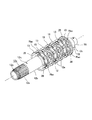
図8に示すように、カウンタ歯車軸12の軸受カラー部材13を介して被動変速歯車nが軸支される中央円筒部12aは、外径が大きく厚肉に構成されており、この厚肉の外周部に周方向に一周する幅狭の周方向溝12cvが第1,第2,第3,第4,第5,第6被動変速歯車n1,n2,n3,n4,n5,n6に対応して軸方向に亘って等間隔に6本形成されるとともに、軸方向に指向した軸方向溝12avが周方向に亘って等間隔に4本形成されている。   As shown in FIG. 8, the central cylindrical portion 12a on which the driven transmission gear n is pivotally supported via the bearing collar member 13 of the counter gear shaft 12 has a large outer diameter and is configured to be thick. A narrow circumferential groove 12cv that goes around in the circumferential direction on the outer periphery corresponds to the first, second, third, fourth, fifth, and sixth driven transmission gears n1, n2, n3, n4, n5, and n6. In addition, six axial grooves 12av are formed at equal intervals in the axial direction, and four axial grooves 12av oriented in the axial direction are formed at equal intervals in the circumferential direction.

さらに、カウンタ歯車軸12の中央円筒部12aの外周部には、4本の軸方向溝12avで区画された4つの部分が各周方向溝12cvにおいて周方向溝12cvの溝幅を隣り合う軸方向溝12av,12av間に亘って長尺に左右均等に拡大した長尺矩形凹部12pと、周方向溝12cvの溝幅を隣り合う軸方向溝12av,12av間の一部で左右均等に拡大した短尺矩形凹部12qとが、軸方向に交互に形成されている。   Further, on the outer peripheral portion of the central cylindrical portion 12a of the counter gear shaft 12, four portions defined by four axial grooves 12av are adjacent to each other in the circumferential direction. A long rectangular recess 12p that is elongated equally between the grooves 12av and 12av in the left and right direction, and a short length in which the groove width of the circumferential groove 12cv is evenly enlarged in the left and right directions in part between the adjacent axial grooves 12av and 12av. Rectangular recesses 12q are alternately formed in the axial direction.

長尺矩形凹部12pの底面の周方向に離れた2か所に軸方向に長尺の楕円形をして周方向溝12cvに跨って若干凹んだスプリング受部12d,12dが形成されている。
また、短尺矩形凹部12qと軸方向溝12avとの間の厚肉部で周方向溝12cv上にピン孔12hが前記カム案内溝12gまで径方向に穿孔されている。
Spring receiving portions 12d and 12d are formed in two axially elongated oval shapes in the axial direction and slightly recessed over the circumferential groove 12cv at two locations on the bottom surface of the long rectangular recess 12p.
Further, a pin hole 12h is formed in the radial direction up to the cam guide groove 12g on the circumferential groove 12cv at a thick portion between the short rectangular recess 12q and the axial groove 12av.

すなわち、カウンタ歯車軸12の中空内周面から周方向の8か所に刻設されたカム案内溝12gの放射方向にピン孔12hが穿孔される。
各周方向溝12cv上にはそれぞれ4か所ピン孔12hが形成される。
That is, the pin hole 12h is drilled in the radial direction of the cam guide groove 12g formed at eight locations in the circumferential direction from the hollow inner peripheral surface of the counter gear shaft 12.
Four pin holes 12h are formed on each circumferential groove 12cv.

スプリング受部12dには、楕円形に巻回された圧縮スプリング22がその端部を嵌装させて設けられる。
ピン孔12hにはピン部材23が摺動自在に嵌挿される。
なお、ピン孔12hが連通するカム案内溝12gの幅は、ピン部材23の外径幅より小さい。
したがって、ピン孔12hを進退するピン部材23がカム案内溝12gに脱落することがないので、カウンタ歯車軸12への係合手段20の組み付けを容易にする。
The spring receiving portion 12d is provided with a compression spring 22 wound in an elliptical shape with its end fitted.
A pin member 23 is slidably inserted into the pin hole 12h.
The cam guide groove 12g communicating with the pin hole 12h is smaller than the outer diameter width of the pin member 23.
Therefore, the pin member 23 that advances and retreats through the pin hole 12h does not fall into the cam guide groove 12g, so that the engagement means 20 can be easily assembled to the counter gear shaft 12.

カム案内溝12gにはカムロッドCが摺動自在に嵌合されるので、ピン孔12hに嵌挿されたピン部材23は中心側端部が対応するカムロッドCのカム面に接し、カムロッドCの移動でカム溝vがピン孔12hに対応するとピン部材23がカム溝vに落ち込み、カム溝v以外の摺接面が対応するとピン部材は摺接面に乗り上げ、カムロッドCの移動により進退する。
ピン孔12h内でのピン部材23の進退は、その遠心側端部を周方向溝12cvの底面より外側に出没させる。
Since the cam rod C is slidably fitted in the cam guide groove 12g, the pin member 23 fitted in the pin hole 12h comes into contact with the cam surface of the corresponding cam rod C at the center end, and the cam rod C moves. When the cam groove v corresponds to the pin hole 12h, the pin member 23 falls into the cam groove v, and when the slidable contact surface other than the cam groove v corresponds, the pin member rides on the slidable contact surface and moves forward and backward by the movement of the cam rod C.
The advancement and retraction of the pin member 23 in the pin hole 12h causes the distal end portion of the pin member 23 to protrude outward from the bottom surface of the circumferential groove 12cv.

以上のような構造のカウンタ歯車軸12の中央円筒部12aの外周部に形成された長尺矩形凹部12pと短尺矩形凹部12qと両凹部間を連通する周方向溝12cvに、揺動爪部材Rが埋設され、軸方向溝12avに揺動爪部材Rを揺動自在に軸支する支軸ピン26が埋設される。
このようにして、全ての揺動爪部材Rが組み付けられた状態を図11に示す。
The swinging claw member R is formed in the circumferential groove 12cv that communicates between the long rectangular recess 12p and the short rectangular recess 12q formed on the outer peripheral portion of the central cylindrical portion 12a of the counter gear shaft 12 having the above-described structure. Is embedded, and a support pin 26 is embedded in the axial groove 12av to pivotally support the swing claw member R.
FIG. 11 shows a state in which all the swinging claw members R are assembled in this way.

図10の分解斜視図には、奇数段歯車(第1,第3,第5被動変速歯車n1,n3,n5)に対応する周方向溝12cvおよび長尺矩形凹部12p,短尺矩形凹部12qに埋設される4個の揺動爪部材Rと、偶数段の偶数段歯車(第2,第4,第6被動変速歯車n2,n4,n6)に対応する周方向溝12cvおよび長尺矩形凹部12p,短尺矩形凹部12qに埋設される4個の揺動爪部材Rとが、互いの相対角度位置関係を維持した姿勢で図示されており、加えて各揺動爪部材Rを軸支する支軸ピン26および各揺動爪部材Rに作用する圧縮スプリング22とピン部材23が示されている。   In the exploded perspective view of FIG. 10, the circumferential grooves 12cv, the long rectangular recesses 12p, and the short rectangular recesses 12q corresponding to the odd-numbered gears (first, third, and fifth driven transmission gears n1, n3, and n5) are embedded. Four oscillating claw members R, and circumferential grooves 12cv and long rectangular recesses 12p corresponding to even-numbered even gears (second, fourth and sixth driven transmission gears n2, n4, n6), The four swinging claw members R embedded in the short rectangular recess 12q are illustrated in a posture maintaining the relative angular positional relationship with each other, and in addition, a support pin that pivotally supports each swinging claw member R. 26 and a compression spring 22 and a pin member 23 acting on each swing claw member R are shown.

揺動爪部材Rは、全て同じ形状のものを使用しており、軸方向視で略円弧状をなし、中央に支軸ピン26が貫通する貫通孔の外周部が欠損して軸受凹部Rdが形成されており、同軸受凹部Rdの揺動中心に関して一方の側に長尺矩形凹部12pに揺動自在に嵌合する幅広矩形の係合爪部Rpが形成され、他方の側にはピン孔12hが形成された周方向溝12cvに揺動自在に嵌合する幅狭のピン受部Rrが延出し、その端部は短尺矩形凹部12qに至り幅広に拡大した幅広端部Rqが形成されている。   The swinging claw members R are all of the same shape, have a substantially arc shape when viewed in the axial direction, and the outer peripheral portion of the through hole through which the support shaft pin 26 penetrates in the center lacks the bearing recess Rd. A wide rectangular engagement claw Rp is formed on one side of the bearing recess Rd so as to be swingably fitted to the long rectangular recess 12p. A pin hole is formed on the other side. A narrow pin receiving portion Rr that slidably fits in the circumferential groove 12cv formed with 12h extends, and an end of the pin receiving portion Rr reaches a short rectangular recess 12q to form a wide end Rq that is widened. Yes.

揺動爪部材Rは、ピン受部Rrがピン孔12hが形成された周方向溝12cvに嵌合し、一方の係合爪部Rpが長尺矩形凹部12pに嵌合するとともに軸受凹部Rdが軸方向溝12avに合致し、他方の幅広端部Rqが短尺矩形凹部12qに嵌合する。
そして、合致した軸受凹部Rdと軸方向溝12avに支軸ピン26が嵌合される。
In the swing claw member R, the pin receiving portion Rr is fitted in the circumferential groove 12cv in which the pin hole 12h is formed, and one engaging claw portion Rp is fitted in the long rectangular recess 12p and the bearing recess Rd is formed. The other wide end Rq is fitted in the short rectangular recess 12q, matching the axial groove 12av.
Then, the support pin 26 is fitted into the matched bearing recess Rd and the axial groove 12av.

揺動爪部材Rは、嵌合する周方向溝12cvに関して左右対称に形成されており、一方の幅広矩形の係合爪部Rpが他方のピン受部Rrおよび幅広端部Rqより重く、支軸ピン26に軸支されてカウンタ歯車軸12とともに回転したとき、遠心力に対して係合爪部Rpが重錘として作用して遠心方向に突出するように揺動爪部材Rを揺動させる。   The swinging claw member R is formed symmetrically with respect to the circumferential groove 12cv to be fitted, and one wide rectangular engagement claw Rp is heavier than the other pin receiving part Rr and the wide end Rq, When the pin 26 is pivotally supported and rotates together with the counter gear shaft 12, the swinging claw member R swings so that the engaging claw Rp acts as a weight against the centrifugal force and protrudes in the centrifugal direction.

揺動爪部材Rは、ピン受部Rrが揺動中心に関して反対側の係合爪部Rp側より幅が狭く形成されている。
また、ピン受部Rrは、ピン部材23を受け止めるだけの幅を具えれば足りるので、揺動爪部材Rを小型に形成することができ、かつ他方の係合爪部Rpの遠心力による揺動を容易にすることができる。
The swinging claw member R is formed such that the pin receiving portion Rr is narrower than the engaging claw Rp side on the opposite side with respect to the swinging center.
Further, since the pin receiving portion Rr only needs to have a width sufficient to receive the pin member 23, the swinging claw member R can be formed in a small size, and the other engaging claw portion Rp can be swung by the centrifugal force. The movement can be facilitated.

周方向に隣り合う揺動爪部材Rは、互いに対称な姿勢にカウンタ歯車軸12に組み付けられるので、互いに所定間隔を存して対向する係合爪部Rp,Rpは共通の長尺矩形凹部12pに嵌合し、他方の互いの近接する幅広端部Rqは共通の短尺矩形凹部12qに嵌合する。   Since the swinging claw members R adjacent to each other in the circumferential direction are assembled to the counter gear shaft 12 in a symmetrical attitude, the engaging claw portions Rp, Rp facing each other with a predetermined interval are the same long rectangular recess 12p. The other wide end Rq adjacent to each other is fitted into a common short rectangular recess 12q.

揺動爪部材Rの係合爪部Rpの内側にカウンタ歯車軸12のスプリング受部12dに一端を支持された圧縮スプリング22が介装され、ピン受部Rrの内側にピン孔12hに嵌挿されたピン部材23がカムロッドCとの間に介装される。   A compression spring 22 supported at one end by a spring receiving portion 12d of the counter gear shaft 12 is interposed inside the engaging claw portion Rp of the swing claw member R, and is inserted into the pin hole 12h inside the pin receiving portion Rr. The pin member 23 is interposed between the cam rod C and the pin member 23.

このようにして、揺動爪部材Rが、支軸ピン26に揺動自在に軸支されてカウンタ歯車軸12の長尺矩形凹部12p,短尺矩形凹部12q,周方向溝12cvに埋設され、一方の係合爪部Rpが圧縮スプリング22により外側に付勢され、他方のピン受部Rrがピン部材23の進退により押圧されることで、圧縮スプリング22の付勢力に抗して揺動爪部材Rが揺動する。   In this way, the swing claw member R is pivotally supported by the support pin 26 and is embedded in the long rectangular recess 12p, the short rectangular recess 12q, and the circumferential groove 12cv of the counter gear shaft 12, The engaging claw portion Rp is urged outward by the compression spring 22, and the other pin receiving portion Rr is pressed by the advancement and retraction of the pin member 23, so that the oscillating claw member resists the urging force of the compression spring 22. R swings.

ピン部材23が遠心方向に進行して揺動爪部材Rを揺動したときは、揺動爪部材Rは係合爪部Rpが長尺矩形凹部12pに没してカウンタ歯車軸12の中央円筒部12aの外周面より外側に突出するものはない。
また、ピン部材23が退行したときは、圧縮スプリング22により付勢された係合爪部Rpがカウンタ歯車軸12の中央円筒部12aの外周面より外側に突出し被動変速歯車nと係合可能とする。
When the pin member 23 advances in the centrifugal direction and swings the swinging claw member R, the swinging claw member R has the engagement claw portion Rp submerged in the long rectangular recess 12p and the central cylinder of the counter gear shaft 12 There is nothing that protrudes outward from the outer peripheral surface of the portion 12a.
When the pin member 23 is retracted, the engaging claw Rp biased by the compression spring 22 protrudes outward from the outer peripheral surface of the central cylindrical portion 12a of the counter gear shaft 12, and can be engaged with the driven transmission gear n. To do.

圧縮スプリング22がカウンタ歯車軸12の軸方向を長径とする楕円形状をなし、楕円形状をした圧縮スプリング22は、長径が揺動爪部材Rのピン受部Rrの幅より大きく、ピン受部Rrを揺動可能に嵌合する周方向に一周に亘って形成される周方向溝12cvを跨いで受け止められるので、カウンタ歯車軸12の加工を容易にするとともに、揺動爪部材Rを安定してカウンタ歯車軸12に組み付けることができる。   The compression spring 22 has an elliptical shape whose major axis is the axial direction of the counter gear shaft 12. The elliptical compression spring 22 has a major axis larger than the width of the pin receiving portion Rr of the swinging claw member R, and the pin receiving portion Rr. Since the counter gear shaft 12 can be easily machined and the swinging claw member R can be stabilized stably. The counter gear shaft 12 can be assembled.

奇数段歯車(第1,第3,第5被動変速歯車n1,n3,n5)に対応する4個の揺動爪部材Rと、偶数段の偶数段歯車(第2,第4,第6被動変速歯車n2,n4,n6)に対応する4個の揺動爪部材Rは、互いに軸中心に90度回転した相対角度位置関係にある。   Four swinging claw members R corresponding to odd-numbered gears (first, third, and fifth driven transmission gears n1, n3, and n5) and even-numbered gears (second, fourth, and sixth driven gears) The four swinging claw members R corresponding to the transmission gears n2, n4, n6) are in a relative angular position relationship rotated 90 degrees around the axis.

奇数段歯車(第1,第3,第5被動変速歯車n1,n3,n5)に対応する4個の揺動爪部材Rは、歯車の正回転方向で当接して各奇数段被動変速歯車n1,n3,n5とカウンタ歯車軸12とが同期して回転するように係合する正回転奇数段揺動爪部材Raoと、歯車の逆回転方向で当接して各奇数段被動変速歯車n1,n3,n5とカウンタ歯車軸12とが同期して回転するように係合する逆回転奇数段係合部材Rboとが、それぞれ対称位置に一対ずつ設けられる。   Four swinging claw members R corresponding to the odd-numbered gears (first, third, and fifth driven transmission gears n1, n3, and n5) are in contact with each other in the forward rotation direction of the gear, and each odd-stage driven transmission gear n1. , N3, n5 and the counter gear shaft 12 are engaged with each other so as to rotate in synchronization with each other, and the odd-numbered driven gears n1, n3 are in contact with each other in the reverse rotation direction of the gear. , N5 and counter gear shaft 12 are provided with a pair of counter-rotating odd-numbered engaging members Rbo that are engaged so as to rotate in synchronization with each other at symmetrical positions.

同様に、偶数段歯車(第2,第4,第6被動変速歯車n2,n4,n6)に対応する4個の揺動爪部材Rは、歯車の正回転方向で当接して各偶数段被動変速歯車n2,n4,n6とカウンタ歯車軸12とが同期して回転するように係合する正回転偶数段揺動爪部材Raeと、歯車の逆回転方向で当接して各偶数段被動変速歯車n2,n4,n6とカウンタ歯車軸12とが同期して回転するように係合する逆回転偶数段係合部材Rbeとが、それぞれ対称位置に一対ずつ設けられる。   Similarly, the four swinging claw members R corresponding to the even-numbered gears (second, fourth, and sixth driven transmission gears n2, n4, and n6) are brought into contact with each other in the forward rotation direction of the gears, and each even-numbered gear is driven. A forward rotation even-numbered-stage swinging claw member Rae engaged so that the transmission gears n2, n4, n6 and the counter gear shaft 12 rotate in synchronization with each other, and the even-numbered driven gears in contact with each other in the reverse rotation direction of the gear. A pair of counter-rotating even-numbered engaging members Rbe that are engaged so that n2, n4, and n6 and the counter gear shaft 12 rotate synchronously are provided in pairs at symmetrical positions.

正回転奇数段揺動爪部材Raoが前記正回転奇数段用カムロッドCaoの移動により進退するピン部材23により揺動し、逆回転奇数段係合部材Rboが前記逆回転奇数段用カムロッドCboの移動により進退するピン部材23により揺動する。
同様に、正回転偶数段揺動爪部材Raeが前記正回転偶数段用カムロッドCaeの移動により進退するピン部材23により揺動し、逆回転偶数段係合部材Rbeが前記逆回転偶数段用カムロッドCbeの移動により進退するピン部材23により揺動する。
The forward rotation odd-stage swinging claw member Rao is swung by the pin member 23 that moves forward and backward by the movement of the forward rotation odd-stage cam rod Cao, and the reverse rotation odd-stage engagement member Rbo is moved by the reverse rotation odd-stage cam rod Cbo. It swings by the pin member 23 that advances and retreats by
Similarly, the forward rotating even-stage swinging claw member Rae is swung by the pin member 23 that moves forward and backward by the movement of the forward-rotating even-numbered cam rod Cae, and the reverse-rotating even-numbered engaging member Rbe The pin member 23 is moved back and forth by the movement of Cbe to swing.

カウンタ歯車軸12に係合手段20を組み込む場合、まず右端の軸受カラー部材13を中央円筒部12aの外周端部に外装し、その軸受カラー部材13の内側の軸方向溝12avに支軸ピン26の一端を嵌入するようにして右端の係合手段20を組み込み、次の軸受カラー部材13を前記支軸ピン26の他端を覆うように外装した後、前段と同じようにして次段の係合手段20を組み込むことを、順次繰り返して、最後に左端の軸受カラー部材13を外装して終了する。   When the engagement means 20 is incorporated in the counter gear shaft 12, first, the right end bearing collar member 13 is externally mounted on the outer peripheral end of the central cylindrical portion 12a, and the support pin 26 is inserted into the axial groove 12av inside the bearing collar member 13. The right end engaging means 20 is incorporated so that one end of the shaft is inserted, and the next bearing collar member 13 is packaged so as to cover the other end of the support pin 26, and then the next stage engagement is performed in the same manner as the previous stage. The incorporation of the combining means 20 is sequentially repeated, and finally the bearing collar member 13 at the left end is packaged to finish.

図12に示すように、軸受カラー部材13は、中央円筒部12aの長尺矩形凹部12pおよび短尺矩形凹部12q以外の軸方向位置に外装され、それは軸方向溝12avに一列に連続して埋設される支軸ピン26の隣り合う支軸ピン26,26に跨って配置され、支軸ピン26および揺動爪部材Rの脱落を防止する。
カウンタ歯車軸12の中央円筒部12aの軸方向溝12avに埋設される支軸ピン26は、中央円筒部12aの外周面に接する深さに埋設されるので、軸受カラー部材13が外装されると、ガタなく固定される。
As shown in FIG. 12, the bearing collar member 13 is sheathed in an axial position other than the long rectangular recess 12p and the short rectangular recess 12q of the central cylindrical portion 12a, and is continuously embedded in a line in the axial groove 12av. The support pin 26 is disposed across the adjacent support pins 26 and 26 to prevent the support pin 26 and the swinging claw member R from falling off.
Since the support pin 26 embedded in the axial groove 12av of the central cylindrical portion 12a of the counter gear shaft 12 is embedded at a depth in contact with the outer peripheral surface of the central cylindrical portion 12a, when the bearing collar member 13 is sheathed. It is fixed without play.

7個の軸受カラー部材13がカウンタ歯車軸12に等間隔に外装され、隣り合う軸受カラー部材13,13間に跨るようにして被動変速歯車nが回転自在に軸支される。
各被動変速歯車nは、左右内周縁部(内周面の左右周縁部)に切欠きが形成されて左右切欠きの間に薄肉環状の突条30が形成されており、この突条30を挟むように左右の軸受カラー部材13,13が切欠きに滑動自在に係合する(図2,図3参照)。
Seven bearing collar members 13 are mounted on the counter gear shaft 12 at equal intervals, and the driven transmission gear n is rotatably supported so as to straddle between the adjacent bearing collar members 13 and 13.
Each driven transmission gear n has a notch formed in the left and right inner periphery (the left and right periphery of the inner peripheral surface), and a thin annular protrusion 30 is formed between the left and right notches. The left and right bearing collar members 13 and 13 are slidably engaged with the notches so as to be sandwiched (see FIGS. 2 and 3).

この各被動変速歯車nの内周面の突条30に係合凸部31が周方向に等間隔に6箇所形成されている(図2,図3,図4,図5参照)。
係合凸部31は、側面視(図4,図5に示す軸方向視)で薄肉円弧状をなし、その周方向の両端面が前記揺動爪部材Rの係合爪部Rpと係合する係合面をなす。
The protrusions 30 on the inner peripheral surface of each driven transmission gear n have six engaging projections 31 formed at equal intervals in the circumferential direction (see FIGS. 2, 3, 4 and 5).
The engagement convex portion 31 has a thin arc shape when viewed from the side (in the axial direction shown in FIGS. 4 and 5), and both end surfaces in the circumferential direction engage with the engagement claw portion Rp of the swing claw member R. An engagement surface is formed.

正回転奇数段揺動爪部材Rao(正回転偶数段揺動爪部材Rae)と逆回転奇数段係合部材Rbo(逆回転偶数段係合部材Rbe)は、互いに対向する側に係合爪部Rp,Rpを延出しており、正回転奇数段揺動爪部材Rao(正回転偶数段揺動爪部材Rae)は被動変速歯車n(およびカウンタ歯車軸12)の正回転方向で係合凸部31に当接して係合し、逆回転奇数段係合部材Rbo(逆回転偶数段係合部材Rbe)は被動変速歯車nの逆の回転方向で、係合凸部31に当接して係合する。   The forward rotation odd-numbered swinging claw member Rao (forward rotation even-numbered swinging claw member Rae) and the reverse rotation odd-numbered step engagement member Rbo (reverse rotation even-numbered step engagement member Rbe) Rp and Rp are extended, and the positive rotation odd-numbered swinging claw member Rao (positive rotation even-numbered swinging claw member Rae) is an engagement convex portion in the positive rotation direction of the driven transmission gear n (and the counter gear shaft 12). The reverse rotation odd-numbered engagement member Rbo (reverse rotation even-numbered engagement member Rbe) contacts and engages the engagement convex portion 31 in the reverse rotation direction of the driven transmission gear n. To do.

なお、正回転奇数段揺動爪部材Rao(正回転偶数段揺動爪部材Rae)は被動変速歯車nの逆の回転方向では係合爪部Rpが外側に突出していても係合せず、同様に、逆回転奇数段係合部材Rbo(逆回転偶数段係合部材Rbe)は被動変速歯車nの正回転方向では係合爪部Rpが外側に突出していても係合しない。   It should be noted that the forward rotation odd-numbered swinging claw member Rao (forward rotation even-numbered swinging claw member Rae) is not engaged in the reverse rotation direction of the driven transmission gear n even if the engagement claw portion Rp protrudes to the outside. In addition, the reverse rotation odd-numbered engagement member Rbo (reverse rotation even-numbered engagement member Rbe) is not engaged in the forward rotation direction of the driven transmission gear n even if the engagement claw Rp protrudes outward.

図13ないし図15を参照して、1速の加速状態から減速比が1段小さい2速状態にシフトアップする際に、第1被動変速歯車n1の係合凸部31が正回転奇数段揺動爪部材Raoの係合爪部Rpに当接して係合しカウンタ歯車軸12を第1被動変速歯車n1と同速度で回転させている状態で、より高速で回転する第2被動変速歯車n2の係合凸部31が正回転偶数段揺動爪部材Raeの係合爪部Rpに追いつき当接してカウンタ歯車軸12を第2被動変速歯車n2とともにより高速度で回転させて変速するので、第1被動変速歯車n1の係合凸部31から正回転奇数段揺動爪部材Raoの係合爪部Rpは自然と離れていき係合が円滑に解除されるため、係合解除に力を要せず滑らかに作動して滑らかなシフトアップを行うことができる。
シフトダウンも同様に滑らかに実行することができる。
Referring to FIGS. 13 to 15, when shifting up from the first-speed acceleration state to the second-speed state where the reduction ratio is one step smaller, the engagement convex portion 31 of the first driven transmission gear n <b> 1 is rotated in an odd number of forward rotations. A second driven transmission gear n2 that rotates at a higher speed while the counter gear shaft 12 is rotating at the same speed as the first driven transmission gear n1 by contacting and engaging with the engaging claw Rp of the moving claw member Rao. Since the engaging convex portion 31 catches up and comes into contact with the engaging claw portion Rp of the forward rotation even-numbered swinging claw member Rae, the counter gear shaft 12 is rotated at a higher speed together with the second driven transmission gear n2 to change the speed. The engagement claw Rp of the positive rotation odd-numbered swinging claw member Rao is naturally separated from the engagement convex portion 31 of the first driven transmission gear n1, and the engagement is smoothly released. It can operate smoothly and perform upshifts smoothly.
Shift down can be performed smoothly as well.

以上のような多段変速機10の組立及び分解手順について以下説明する。
まず、多段変速機10の分解手順について図16ないし図29に従って説明する。
図16は、機関ケース1から多段変速機10の被動変速歯車n群を軸支したカウンタ歯車軸12を、側壁1RRおよびシフトドラム67とともに取り出したものを、治具ベース80に支持させた状態を示している。
カウンタ歯車軸12は、中央円筒部12aに軸受カラー部材13を介して被動変速歯車nが軸支され、両側に嵌着されたワッシャ14L,14Rにより挟まれており、右側円筒部12cに嵌合されたベアリング7Rを介して側壁1RRに支持されている。
The procedure for assembling and disassembling the multi-stage transmission 10 as described above will be described below.
First, the disassembly procedure of the multi-stage transmission 10 will be described with reference to FIGS.
FIG. 16 shows a state in which the counter gear shaft 12 supporting the driven transmission gear n group of the multi-stage transmission 10 from the engine case 1 together with the side wall 1RR and the shift drum 67 is supported by the jig base 80. Show.
The counter gear shaft 12 is supported by a central cylindrical portion 12a with a driven transmission gear n via a bearing collar member 13, and is sandwiched between washers 14L and 14R fitted on both sides, and is fitted to the right cylindrical portion 12c. It is supported on the side wall 1RR via the bearing 7R.

治具ベース80の端部には、カウンタ歯車軸12の左側円筒部12bを挟持するクランプ機構81が立設されている。
クランプ機構81の上下の挟持部81a,81bがカウンタ歯車軸12の左側円筒部12bを挟持して固定支持した状態で、カウンタ歯車軸12を水平にして治具ベース80が側壁1RRを摺動自在に支持している。
A clamp mechanism 81 that holds the left cylindrical portion 12 b of the counter gear shaft 12 is erected at the end of the jig base 80.
With the upper and lower clamping portions 81a and 81b of the clamp mechanism 81 holding and supporting the left cylindrical portion 12b of the counter gear shaft 12, the jig base 80 can slide on the side wall 1RR with the counter gear shaft 12 horizontal. I support it.

したがって、カウンタ歯車軸12の左側円筒部12bが固定された状態で、側壁1RRを右方(図16,17の右方)に移動すると、図17に示すように、側壁1RRと一体にベアリング7Rおよびシフトドラム67が移動し、シフトドラム67のシフト溝67vに嵌合したシフトピン58を介してコントロールロッド操作子55が右方に引っ張られる。
コントロールロッド操作子55が右方に引っ張られて移動すると、ベアリング56を介してコントロールロッド51が移動し、コントロールロッド51はロストモーション機構52,53を介して8本のカムロッドCを伴ってカウンタ歯車軸12の中空部から引き抜かれる(図17参照)。
Accordingly, when the side wall 1RR is moved rightward (rightward in FIGS. 16 and 17) with the left cylindrical portion 12b of the counter gear shaft 12 fixed, as shown in FIG. 17, the bearing 7R is integrated with the side wall 1RR. Then, the shift drum 67 moves, and the control rod operating element 55 is pulled rightward through the shift pin 58 fitted in the shift groove 67v of the shift drum 67.
When the control rod operator 55 is pulled and moved to the right, the control rod 51 is moved via the bearing 56, and the control rod 51 is accompanied by the eight cam rods C via the lost motion mechanisms 52 and 53 and the counter gear. It is pulled out from the hollow part of the shaft 12 (see FIG. 17).

コントロールロッド51がカムロッドCを伴って途中まで引き抜かれたところで、コントロールロッド51の周囲にロストモーション機構52,53とともに8本のカムロッドCを組付けた状態のところを半割の円筒部材であるシフトロッドホルダ82が囲繞し、周囲をタイラップ83で締め付けて一纏めにする(図18参照)。   When the control rod 51 is pulled out partway along with the cam rod C, the shift of the eight cam rods C together with the lost motion mechanisms 52 and 53 around the control rod 51 is a half cylindrical member. The rod holder 82 surrounds, and the periphery is fastened together with a tie wrap 83 (see FIG. 18).

そして、シフトロッドホルダ82に囲繞されてコントロールロッド51がカムロッドCとともにカウンタ歯車軸12の中空部から引き抜かれる(図19参照)。
引き抜かれたコントロールロッド51とカムロッドCは、組付けられた状態でシフトロッドホルダ82に囲繞されて、一体に取り扱うことができ、カウンタ歯車軸12の中空部に挿入および抜き出し等を容易にし、組立分解の作業性を良好にしている。
The control rod 51 is surrounded by the shift rod holder 82 and pulled out from the hollow portion of the counter gear shaft 12 together with the cam rod C (see FIG. 19).
The pulled out control rod 51 and cam rod C are surrounded by the shift rod holder 82 and can be handled as a single unit, and can be easily inserted into and removed from the hollow portion of the counter gear shaft 12 for assembly. The disassembly workability is improved.

こうしてコントロールロッド51をカムロッドCとともにカウンタ歯車軸12の中空部から引き抜いた後に、代わりにカウンタロッド85がカウンタ歯車軸12の中空部に挿入する(図20参照)。
カウンタロッド85は、円筒部材であり、カウンタ歯車軸12の中空内周面に形成されたカムロッドCが摺動自在に嵌挿されていた8本のカム案内溝12gに代わりに嵌挿する突条85aが形成されており、端部にはプラグ部材86が嵌着されている。
After the control rod 51 is pulled out from the hollow portion of the counter gear shaft 12 together with the cam rod C in this way, the counter rod 85 is inserted into the hollow portion of the counter gear shaft 12 instead (see FIG. 20).
The counter rod 85 is a cylindrical member, and a ridge that is inserted in place of the eight cam guide grooves 12g into which the cam rod C formed on the hollow inner peripheral surface of the counter gear shaft 12 is slidably inserted. 85a is formed, and a plug member 86 is fitted to the end portion.

したがって、カウンタロッド85をカウンタ歯車軸12の中空部に挿入すると、突条85aが各カム案内溝12gに嵌挿されて全てのピン部材23をカウンタ歯車軸12の外周方向に押し出し、全ての揺動爪部材Rを圧縮スプリング22に抗して揺動して、揺動爪部材Rの係合爪部Rpを第2歯車軸12の外周面から内側に没して全ての被動変速歯車nと揺動爪部材Rの係合爪部Rpの係合を解除することができる。   Therefore, when the counter rod 85 is inserted into the hollow portion of the counter gear shaft 12, the protrusions 85a are inserted into the cam guide grooves 12g to push out all the pin members 23 toward the outer periphery of the counter gear shaft 12, thereby The moving claw member R is swung against the compression spring 22, and the engaging claw portion Rp of the swinging claw member R is sunk inward from the outer peripheral surface of the second gear shaft 12, so that all the driven transmission gears n The engagement of the engaging claw Rp of the swing claw member R can be released.

このカウンタロッド85とともに、第1ホルダベース87がその円筒本体87aにアウタカラー90を外周に嵌合しセットした状態で、また円筒本体87aの左端に中空円板状の蓋部材92を嵌合保持した状態で、円筒本体87aをカウンタ歯車軸12の右端に当接する。   Along with this counter rod 85, the first holder base 87 is fitted and held with a hollow disc-like lid member 92 at the left end of the cylindrical body 87a with the outer collar 90 fitted and set to the outer circumference of the cylindrical body 87a. In this state, the cylindrical main body 87a is brought into contact with the right end of the counter gear shaft 12.

第1ホルダベース87は、円筒本体87aの一端がフランジ状に展開して台座87bを形成しており、円筒本体87aは外径がカウンタ歯車軸12の外径(被動変速歯車nが軸支される中央円筒部12aの外径)と等しく、内径がカウンタ歯車軸12の右側円筒部12cの外径に略等しい。
なお、円筒本体87aの内周には左端寄りに鍔部87cが形成されており、カウンタロッド85の右端に嵌着されたプラグ部材86の突起部を嵌入して保持することができ、カウンタロッド85の右端を保持した状態でカウンタロッド85をカウンタ歯車軸12の中空部に挿入することができる。
In the first holder base 87, one end of a cylindrical main body 87a is developed in a flange shape to form a pedestal 87b. The cylindrical main body 87a has an outer diameter that is the outer diameter of the counter gear shaft 12 (the driven transmission gear n is pivotally supported). And the inner diameter is substantially equal to the outer diameter of the right cylindrical portion 12c of the counter gear shaft 12.
A flange 87c is formed near the left end on the inner periphery of the cylindrical main body 87a, and the protrusion of the plug member 86 fitted to the right end of the counter rod 85 can be fitted and held. The counter rod 85 can be inserted into the hollow portion of the counter gear shaft 12 with the right end of 85 held.

また、アウタカラー90は、内径が第1ホルダベース87の円筒本体87aおよびカウンタ歯車軸12の中央円筒部12aの外径と略等しい円筒部材であり、カウンタ歯車軸12の中央円筒部12aの外周面に嵌合される複数の揺動爪部材Rの外周面から突出する係合爪部Rpが進入可能な孔部90hが複数形成されている。   The outer collar 90 is a cylindrical member having an inner diameter substantially equal to the outer diameter of the cylindrical main body 87a of the first holder base 87 and the central cylindrical portion 12a of the counter gear shaft 12, and the outer periphery of the central cylindrical portion 12a of the counter gear shaft 12 A plurality of hole portions 90h into which the engaging claw portions Rp protruding from the outer peripheral surfaces of the plurality of swinging claw members R fitted to the surface can enter are formed.

こうしてカウンタ歯車軸12にカウンタロッド85を挿入し、第1ホルダベース87を移動して、円筒本体87aをカウンタ歯車軸12の中央円筒部12aの側壁に当接すると、図21に示すように、カウンタロッド85の右端のプラグ部材86がカウンタ歯車軸12の内部に入り、カウンタ歯車軸12の右側円筒部12cが第1ホルダベース87の円筒本体87a内に嵌入して鍔部87cに当接する。
第1ホルダベース87の円筒本体87aはカウンタ歯車軸12の中央円筒部12aと外周面が同一周面をなし、円筒本体87aの左端に保持された蓋部材92は右端の第1被動変速歯車n1に接する。
When the counter rod 85 is thus inserted into the counter gear shaft 12, the first holder base 87 is moved, and the cylindrical main body 87a is brought into contact with the side wall of the central cylindrical portion 12a of the counter gear shaft 12, as shown in FIG. The plug member 86 at the right end of the counter rod 85 enters the counter gear shaft 12, and the right cylindrical portion 12c of the counter gear shaft 12 is fitted into the cylindrical main body 87a of the first holder base 87 and comes into contact with the flange portion 87c.
The cylindrical body 87a of the first holder base 87 has the same outer peripheral surface as the central cylindrical portion 12a of the counter gear shaft 12, and the lid member 92 held at the left end of the cylindrical body 87a is the first driven transmission gear n1 at the right end. To touch.

クランプ機構81の挟持を解除し、カウンタ歯車軸12が第1ホルダベース87に結合した状態で、第1ホルダベース87を下側にして立て、第1ホルダベース87の台座87bで保持する(図22参照)。
カウンタ歯車軸12とカウンタロッド85は第1ホルダベース87に支持され、被動変速歯車n群はアウタカラー90によって蓋部材92を介して支持される。
With the clamping mechanism 81 released from being clamped and the counter gear shaft 12 being coupled to the first holder base 87, the first holder base 87 is placed on the lower side and held on the base 87b of the first holder base 87 (see FIG. 22).
The counter gear shaft 12 and the counter rod 85 are supported by the first holder base 87, and the driven transmission gear n group is supported by the outer collar 90 via the lid member 92.

そして、図22に示すように、ギアホルダ91を上方から被動変速歯車n群に被せる。
ギアホルダ91は、円錐筒状の周壁91aの小径の端部に中空の底壁91bが形成されたカップ状をしたもので、大径の開口側を下にして、大径の第1被動変速歯車n1から上に順に径を小さくした被動変速歯車n群に被せると、ギアホルダ91は中空の底壁91bが最上段の第6被動変速歯車n6の当接して支持され、被動変速歯車n群を周壁91aが囲繞し、蓋部材92が周壁91aの下側の大径の開口に蓋をする形となる。
なお、カウンタ歯車軸12の左側円筒部12bに圧入され中央円筒部12aの上側側壁面に接して固着されたワッシャ14Lが最上段の第6被動変速歯車n6を回転自在に軸支する軸受カラー部材13を上から押さえている。
Then, as shown in FIG. 22, the gear holder 91 is put on the driven transmission gear n group from above.
The gear holder 91 has a cup shape in which a hollow bottom wall 91b is formed at a small-diameter end of a conical tube-shaped peripheral wall 91a, and a large-diameter first driven transmission gear with the large-diameter opening side down. When the gear holder 91 is put on a group of driven transmission gears n whose diameters are reduced from n1 in order, the hollow bottom wall 91b of the gear holder 91 is supported by the uppermost sixth driven transmission gear n6, and the driven transmission gear n group is surrounded by a peripheral wall. 91a surrounds and the lid member 92 covers the large-diameter opening on the lower side of the peripheral wall 91a.
Note that a bearing collar member in which a washer 14L press-fitted into the left cylindrical portion 12b of the counter gear shaft 12 and fixed in contact with the upper side wall surface of the central cylindrical portion 12a rotatably supports the sixth driven transmission gear n6 at the uppermost stage. Holds 13 from above.

この状態で、アウタカラー90を上方に持ち上げ、アウタカラー90と第1ホルダベース87の台座87bとの間にスペーサ93を挟むと、図23に示すように、アウタカラー90は第1ホルダベース87に対して蓋部材92を介して被動変速歯車n群をギアホルダ91とともに上方に移動し、同時にワッシャ14Lがカウンタ歯車軸12に固着されていることからカウンタ歯車軸12もカウンタロッド85とともに上方に移動する。   In this state, when the outer collar 90 is lifted upward and the spacer 93 is sandwiched between the outer collar 90 and the base 87b of the first holder base 87, the outer collar 90 is attached to the first holder base 87 as shown in FIG. On the other hand, the driven transmission gear n group is moved upward together with the gear holder 91 via the lid member 92, and at the same time the washer 14L is fixed to the counter gear shaft 12, so that the counter gear shaft 12 is also moved upward together with the counter rod 85. To do.

そして、カウンタ歯車軸12の上端にキャップ94を被せ、キャップ94の上からハンマーなどで軽く叩くと、ワッシャ14Lが被動変速歯車n群および軸受カラー部材13に当接して保持された状態で、カウンタ歯車軸12が下降し、ワッシャ14Lはカウンタ歯車軸12との固着を解かれる。
カウンタ歯車軸12は下降して第1ホルダベース87の円筒本体87aに当接して支持される。
カウンタ歯車軸12からキャップ94およびワッシャ14Lを外し、スペーサ93も外すと、アウタカラー90とともに被動変速歯車n群が下降し、図25に示す状態となる。
Then, when a cap 94 is put on the upper end of the counter gear shaft 12, and the tap 94 is tapped lightly with a hammer or the like, the washer 14L is held in contact with the driven transmission gear n group and the bearing collar member 13, and the counter The gear shaft 12 is lowered, and the washer 14L is released from the counter gear shaft 12.
The counter gear shaft 12 descends and is supported in contact with the cylindrical body 87a of the first holder base 87.
When the cap 94 and the washer 14L are removed from the counter gear shaft 12, and the spacer 93 is also removed, the driven transmission gear n group is lowered together with the outer collar 90, and the state shown in FIG. 25 is obtained.

そして、上方に突出したカウンタ歯車軸12の左側円筒部12bに第2ホルダベース95を嵌合する。
第2ホルダベース95は、カウンタ歯車軸12の中央円筒部12aと同じ外径を有し左側円筒部12bの外径に略等しい内径を有する円筒本体95aと同円筒本体95aの一端がフランジ状に展開して台座95bとを形成している。
Then, the second holder base 95 is fitted to the left cylindrical portion 12b of the counter gear shaft 12 protruding upward.
The second holder base 95 has a cylindrical main body 95a having the same outer diameter as the central cylindrical portion 12a of the counter gear shaft 12 and an inner diameter substantially equal to the outer diameter of the left cylindrical portion 12b, and one end of the cylindrical main body 95a has a flange shape. The base 95b is formed by unfolding.

この第2ホルダベース95の円筒本体95aを台座95bを上にしてカウンタ歯車軸12の左側円筒部12bに上から嵌合すると、円筒本体95aがカウンタ歯車軸12の中央円筒部12aに当接して、円筒本体95aとカウンタ歯車軸12が同一外周面をなして連結する。   When the cylindrical body 95a of the second holder base 95 is fitted to the left cylindrical portion 12b of the counter gear shaft 12 from above with the pedestal 95b facing upward, the cylindrical main body 95a comes into contact with the central cylindrical portion 12a of the counter gear shaft 12. The cylindrical body 95a and the counter gear shaft 12 are connected to form the same outer peripheral surface.

この状態で上下を逆さにすると、カウンタ歯車軸12の中空部へのカウンタロッド85の挿入により揺動爪部材Rの係合爪部Rpを第2歯車軸12の外周面から内側に没して全ての被動変速歯車nと揺動爪部材Rの係合爪部Rpの係合を解除しているので、図26に示すように、重力により被動変速歯車n群はギアホルダ91および蓋部材92とともに下降してカウンタ歯車軸12の中央円筒部12aから第2ホルダベース95の円筒本体95aに移り、一緒に下降するアウタカラー90は被動変速歯車n群に代わってカウンタ歯車軸12の中央円筒部12aに移る。   In this state, when the top and bottom are turned upside down, the engaging claw Rp of the swing claw member R is immersed inward from the outer peripheral surface of the second gear shaft 12 by inserting the counter rod 85 into the hollow portion of the counter gear shaft 12. Since the engagement of all the driven transmission gears n and the engaging claws Rp of the swinging claw members R is released, the driven transmission gears n group together with the gear holder 91 and the lid member 92 by gravity as shown in FIG. The outer collar 90 descending and moving from the central cylindrical portion 12a of the counter gear shaft 12 to the cylindrical main body 95a of the second holder base 95 is lowered together with the central cylindrical portion 12a of the counter gear shaft 12 instead of the driven transmission gear n group. Move on.

なお、逆に組立時には、カウンタ歯車軸12の中央円筒部12aにアウタカラー90に代わって被動変速歯車n群を嵌合することができる。
このように、アウタカラー90をカウンタロッド85と組み合わせて使用して、カウンタ歯車軸12に対して被動変速歯車n群とアウタカラー90とを交代して組み込みまたは取り外しすることができ、多段変速機の組立および分解作業を容易にすることができる。
また、被動変速歯車n群はギアホルダ91に収容され蓋部材92で蓋されて、一体として取り扱うことができるようにしているので、被動変速歯車n群のカウンタ歯車軸12への取り付けおよび取り外しを簡単にし、多段変速機の組立および分解作業を容易にしている。
On the other hand, at the time of assembly, the driven transmission gear n group can be fitted to the central cylindrical portion 12a of the counter gear shaft 12 in place of the outer collar 90.
In this way, the outer collar 90 can be used in combination with the counter rod 85, and the driven transmission gear n group and the outer collar 90 can be alternately incorporated into or removed from the counter gear shaft 12. Assembling and disassembling work can be facilitated.
Further, since the driven transmission gear n group is accommodated in the gear holder 91 and covered with the lid member 92 so that it can be handled as a unit, the driven transmission gear n group can be easily attached to and detached from the counter gear shaft 12. This facilitates assembly and disassembly work of the multi-stage transmission.

さらに、第1ホルダベース87の円筒本体87aをカウンタ歯車軸12の中央円筒部12aに当接して同一外周面をなして連結することで、アウタカラー90の円筒本体87aとカウンタ歯車軸12の中央円筒部12aとの間の移動を円滑にし、よって被動変速歯車n群のカウンタ歯車軸12への取り付けおよび取り外しを円滑にし、多段変速機の組立および分解作業を益々容易にしている。   Further, the cylindrical body 87a of the first holder base 87 is brought into contact with the central cylindrical portion 12a of the counter gear shaft 12 so as to form the same outer peripheral surface, thereby connecting the cylindrical main body 87a of the outer collar 90 and the center of the counter gear shaft 12. The movement to and from the cylindrical portion 12a is made smooth, and hence the attachment and detachment of the driven transmission gear n group to and from the counter gear shaft 12 are made smooth, and the assembly and disassembly work of the multi-stage transmission is made easier.

前述のようにして、ギアホルダ91の底壁91bが第2ホルダベース95の台座95bに当接して下降を停止すると、被動変速歯車n群は完全に第2ホルダベース95の円筒本体95aに移り、アウタカラー90はカウンタ歯車軸12の中央円筒部12aに移り、中央円筒部12aの外周を覆う(図27参照)。
図27は、この状態から第1ホルダベース87を取り外すとともに、カウンタロッド85をカウンタ歯車軸12の中空部から抜き取った状態を示している。
As described above, when the bottom wall 91b of the gear holder 91 comes into contact with the base 95b of the second holder base 95 and stops descending, the driven transmission gear n group is completely moved to the cylindrical body 95a of the second holder base 95, The outer collar 90 moves to the central cylindrical portion 12a of the counter gear shaft 12 and covers the outer periphery of the central cylindrical portion 12a (see FIG. 27).
FIG. 27 shows a state where the first holder base 87 is removed from this state and the counter rod 85 is removed from the hollow portion of the counter gear shaft 12.

なお、カウンタロッド85をカウンタ歯車軸12の中空部から抜き取ることで、全てのピン部材23の押さえが解かれ、全ての揺動爪部材Rは圧縮スプリング22により揺動して、揺動爪部材Rの係合爪部Rpを第2歯車軸12の外周面から外側に突出し、アウタカラー90の孔部90hに進入して係合する。
したがって、図28に示すように、カウンタ歯車軸12を第2ホルダベース95の円筒本体95aから上方に引き抜くと、アウタカラー90もカウンタ歯車軸12に係止して一緒になって離れる。
By pulling out the counter rod 85 from the hollow portion of the counter gear shaft 12, all the pin members 23 are released, and all the swing claw members R are swung by the compression springs 22, so that the swing claw members The engagement claw portion Rp of R protrudes outward from the outer peripheral surface of the second gear shaft 12, and enters and engages with the hole 90h of the outer collar 90.
Therefore, as shown in FIG. 28, when the counter gear shaft 12 is pulled upward from the cylindrical body 95a of the second holder base 95, the outer collar 90 is also locked to the counter gear shaft 12 and separated together.

第2ホルダベース95に軸支され、ギアホルダ91で覆われ、蓋部材92で蓋された被動変速歯車n群は、全体を上下逆さにして、第2ホルダベース95を上方に抜き去り、図29に示すように、ギアホルダ91を上方に取り去ることで、後は簡単に被動変速歯車n群を軸受カラー部材13とともに分解することができる。
なお、カウンタ歯車軸12側も、中空部にカウンタロッド85を挿入することで、アウタカラー90をカウンタ歯車軸12の中央円筒部12aから取り外すことができるので、後はカウンタ歯車軸12の中央円筒部12aから各揺動爪部材R,ピン部材23,圧縮スプリング22,支軸ピン26を容易に分解することができる。
The driven transmission gear n group supported by the second holder base 95, covered with the gear holder 91, and covered with the lid member 92 is turned upside down, and the second holder base 95 is removed upward, and FIG. As shown in FIG. 4, the gear holder 91 is removed upward so that the driven transmission gear n group can be easily disassembled together with the bearing collar member 13 thereafter.
Note that the outer collar 90 can be removed from the central cylindrical portion 12a of the counter gear shaft 12 by inserting the counter rod 85 into the hollow portion on the counter gear shaft 12 side. Each swinging claw member R, pin member 23, compression spring 22, and spindle pin 26 can be easily disassembled from the portion 12a.

以上が多段変速機10の分解手順であるが、この分解手順を逆に実行すれば多段変速機10の組立手順となる。
しかし、分解作業とは異なり、組立作業において、カウンタ歯車軸12の中央円筒部12aに揺動爪部材R,ピン部材23,圧縮スプリング22,支軸ピン26を組み付けるのが容易ではない。
そこで、揺動爪部材R等の組付け用の治具であるラチェットセットホルダ100を使用した。
The above is the disassembling procedure of the multi-stage transmission 10. If the disassembling procedure is executed in reverse, the assembling procedure of the multi-stage transmission 10 is obtained.
However, unlike the disassembly operation, it is not easy to assemble the swinging claw member R, the pin member 23, the compression spring 22 and the support shaft pin 26 to the central cylindrical portion 12a of the counter gear shaft 12 in the assembly operation.
Therefore, a ratchet set holder 100 which is a jig for assembling the swinging claw member R and the like is used.

ラチェットセットホルダ100は、カウンタ歯車軸12の中央円筒部12aの外径と略等しい内径の円筒本体100aと円筒本体100aの一方の開口端が拡径した環状支持部100bからなるとともに、円筒本体100aの他方の端開口端に揺動爪部材Rの1個分が露出可能な矩形の開口部100cが切り欠かれている。 The ratchet set holder 100 includes a cylindrical main body 100a having an inner diameter substantially equal to the outer diameter of the central cylindrical portion 12a of the counter gear shaft 12 and an annular support portion 100b in which one open end of the cylindrical main body 100a has an enlarged diameter. A rectangular opening portion 100c from which one of the swinging claw members R can be exposed is cut out at the other end opening end.

図30を参照して、第2ホルダベース95に嵌合支持されたカウンタ歯車軸12に、上からラチェットセットホルダ100の円筒本体100aを開口部100cを下にして嵌合し、まずカウンタ歯車軸12の第1被動変速歯車n1に用いられる揺動爪部材Rが組み込まれる場所に開口部100cを合わせ,開口部100cから揺動爪部材R,ピン部材23,圧縮スプリング22,支軸ピン26を組み込む。
第1被動変速歯車n1には4個の揺動爪部材Rが必要であるので、ラチェットセットホルダ100を回転して順次開口部100cを所要場所に合わせて揺動爪部材R等を組み込んでいく。
なお、組み込まれた揺動爪部材R等は外周をラチェットセットホルダ100の円筒本体100aの周壁で覆われて外れることはない。
Referring to FIG. 30, the cylindrical body 100a of the ratchet set holder 100 is fitted from above to the counter gear shaft 12 fitted and supported by the second holder base 95 with the opening 100c facing downward. The opening 100c is aligned with the place where the swinging claw member R used for the 12th first driven transmission gear n1 is assembled, and the swinging claw member R, the pin member 23, the compression spring 22, and the support pin 26 are connected to the opening 100c. Include.
Since the first driven transmission gear n1 requires four swinging claw members R, the ratchet set holder 100 is rotated, and the swinging claw member R and the like are sequentially assembled so that the opening 100c is aligned with the required location. .
The built-in swinging claw member R and the like are not removed by being covered with the peripheral wall of the cylindrical main body 100a of the ratchet set holder 100.

第1被動変速歯車n1用の4個の揺動爪部材R等が組み込まれると、ラチェットセットホルダ100を1段下げて、第2被動変速歯車n2用の4個の揺動爪部材R等が同様の作業によって組み込まれ、以後第3,第4,第5,第6被動変速歯車n3,n4,n5,n6用の揺動爪部材R等について同じ組み込み作業を繰り返して組み込んでいく。 When the four swinging claw members R for the first driven transmission gear n1 are incorporated, the ratchet set holder 100 is lowered by one step, and the four swinging claw members R for the second driven transmission gear n2 are moved. The same assembling operation is repeated for the third, fourth, fifth, and sixth driven transmission gears n3, n4, n5, and n6.

このように、ラチェットセットホルダ100を用いることにより、カウンタ歯車軸12の中央円筒部12aの複数箇所に揺動爪部材R,ピン部材23,圧縮スプリング22,支軸ピン26を組み込む煩瑣な作業を容易にし、円滑に速やかに作業を進めることができる。 As described above, by using the ratchet set holder 100, the troublesome work of incorporating the swinging claw member R, the pin member 23, the compression spring 22, and the support shaft pin 26 at a plurality of locations in the central cylindrical portion 12a of the counter gear shaft 12 is achieved. It is easy and can proceed smoothly and promptly.

こうして、全ての揺動爪部材R等がカウンタ歯車軸12の中央円筒部12aに組み込まれると、ラチェットセットホルダ100は揺動爪部材R等を組み込んだカウンタ歯車軸12の中央円筒部12aの外周を覆う(図31参照)。
ここで、カウンタロッド85を上からカウンタ歯車軸12の中空部に挿入して、揺動爪部材Rの係合爪部Rpを第2歯車軸12の外周面から内側に没しておき、次いでアウタカラー90を上方からラチェットセットホルダ100の上端の環状支持部100bに同軸に嵌合する(図32参照)。
Thus, when all the swinging claw members R and the like are incorporated in the central cylindrical portion 12a of the counter gear shaft 12, the ratchet set holder 100 has an outer periphery of the central cylindrical portion 12a of the counter gear shaft 12 incorporating the swinging claw members R and the like. (See FIG. 31).
Here, the counter rod 85 is inserted into the hollow portion of the counter gear shaft 12 from above, and the engaging claw portion Rp of the swing claw member R is immersed inside from the outer peripheral surface of the second gear shaft 12, The outer collar 90 is coaxially fitted to the annular support portion 100b at the upper end of the ratchet set holder 100 from above (see FIG. 32).

この状態でラチェットセットホルダ100をアウタカラー90とともに下降すると、ラチェットセットホルダ100はカウンタ歯車軸12の中央円筒部12aから第2ホルダベース95の円筒本体95aに移り、ラチェットセットホルダ100と入れ替わりにアウタカラー90がカウンタ歯車軸12の中央円筒部12aに移る(図33参照)。 When lowered the ratchet set holder 100 together with the outer collar 90 in this state, the ratchet set holder 100 is moved from the central cylindrical portion 12a of the counter gear shaft 12 in a cylindrical body 95a of the second holder base 95, outer ratchet set holder 100 and turnover The collar 90 moves to the central cylindrical portion 12a of the counter gear shaft 12 (see FIG. 33).

ここでカウンタロッド85をカウンタ歯車軸12の中空部から抜き取ることで、全ての揺動爪部材Rの係合爪部Rpを第2歯車軸12の外周面から外側に突出し、アウタカラー90の孔部90hに進入して係合する。
したがって、図34に示すように、カウンタ歯車軸12を第2ホルダベース95の円筒本体95aから上方に引き抜くと、アウタカラー90もカウンタ歯車軸12に係止して一緒になって離れる。
Here, by pulling out the counter rod 85 from the hollow portion of the counter gear shaft 12, the engaging claw portions Rp of all the swing claw members R protrude outward from the outer peripheral surface of the second gear shaft 12, and the holes of the outer collar 90 Part 90h is entered and engaged.
Therefore, as shown in FIG. 34, when the counter gear shaft 12 is pulled upward from the cylindrical main body 95a of the second holder base 95, the outer collar 90 is also locked to the counter gear shaft 12 and separated together.

こうしてカウンタ歯車軸12の中央円筒部12aに全ての揺動爪部材Rを組み込んだ状態でアウタカラー90により覆われた状態を容易に構成することができる。
このカウンタ歯車軸12側の状態は、前記図28に示す状態であり、一方で、同図28に示すように、台座95bで支持して立設した第2ホルダベース95の円筒本体95aにギアホルダ91を中空の底壁91bを下にして嵌合し、次いで、ギアホルダ91内に円筒本体95aに軸支されるように、軸受カラー部材13,第6被動変速歯車n6,軸受カラー部材13,第5被動変速歯車n5,…, ,…,第1被動変速歯車n1,軸受カラー部材13の順に重ねていき、最後に蓋部材92で蓋をすれば、被動変速歯車n群側が構成される。
Thus, it is possible to easily configure a state where all the swinging claw members R are incorporated in the central cylindrical portion 12a of the counter gear shaft 12 and covered with the outer collar 90.
The counter gear shaft 12 side is in the state shown in FIG. 28. On the other hand, as shown in FIG. 28, the gear holder is mounted on the cylindrical main body 95a of the second holder base 95 supported upright by the pedestal 95b. 91 is fitted with the hollow bottom wall 91b down, and then the bearing collar member 13, the sixth driven transmission gear n6, the bearing collar member 13, ..,..., First driven transmission gear n1, bearing collar member 13 are stacked in this order, and finally the lid member 92 is used to cover the driven transmission gear n group.

以後の組立手順は、前記した分解手順を逆に辿ればよく、多段変速機の組立作業も簡単に行われる。
以上のように、適切な治具を用いることで、多段変速機の組立および分解作業を容易にし、作業時間の短縮、作業労力の軽減を図ることができる。
Subsequent assembling procedures may be performed by reversing the above disassembling procedure, and the assembling work of the multi-stage transmission can be easily performed.
As described above, by using an appropriate jig, it is possible to facilitate the assembly and disassembly of the multi-stage transmission, shorten the work time, and reduce the work effort.

m…駆動変速歯車、m1〜m6…第1〜第6駆動変速歯車、
n…被動変速歯車、n1〜n6…第1〜第6被動変速歯車、
10…多段変速機、11…メイン歯車軸、12…カウンタ歯車軸、13…軸受カラー部材、
20…係合手段、23…ピン部材、31…係合凸部、
32…出力スプロケット、37…袋ナット、38…チェーン、
C…カムロッド、p…係止爪、v…カム溝、R…揺動爪部材、Rp…係合爪部、
50…変速駆動手段、51…コントロールロッド、51a,51b…外周凹部、51as,51bs…拡径ストッパ部、52,53…ロストモーション機構、52h,53h…スプリングホルダ、52ha,53ha…内周凹部、52s,53s…コイルスプリング、52c,53c…コッタ、55…コントロールロッド操作子、58…シフトピン、59…係合ピン、60…溝条、67…シフトドラム、67v…シフト溝、
80…治具ベース、81…クランプ機構、82…シフトロッドホルダ、85…カウンタロッド、86…プラグ部材、87…第1ホルダベース、87a…円筒本体、87c…鍔部、90…アウタカラー、90h…孔部、91…ギアホルダ、91a…周壁、91b…底壁、92…蓋部材、93…スペーサ、94…キャップ、95…第2ホルダベース、95a…円筒本体、100…ラチェットセットホルダ、100c…開口部。
m: drive transmission gear, m1 to m6 ... first to sixth drive transmission gears,
n: driven transmission gear, n1 to n6: first to sixth driven transmission gears,
10 ... multi-speed transmission, 11 ... main gear shaft, 12 ... counter gear shaft, 13 ... bearing collar member,
20 ... engaging means, 23 ... pin member, 31 ... engaging convex part,
32 ... output sprocket, 37 ... cap nut, 38 ... chain,
C ... cam rod, p ... locking claw, v ... cam groove, R ... swinging claw member, Rp ... engagement claw part,
50: Variable speed drive means, 51: Control rod, 51a, 51b ... Outer peripheral recess, 51as, 51bs ... Diameter expansion stopper, 52, 53 ... Lost motion mechanism, 52h, 53h ... Spring holder, 52ha, 53ha ... Inner peripheral recess, 52s, 53s ... coil spring, 52c, 53c ... cotter, 55 ... control rod operator, 58 ... shift pin, 59 ... engagement pin, 60 ... groove, 67 ... shift drum, 67v ... shift groove,
80 ... Jig base, 81 ... Clamp mechanism, 82 ... Shift rod holder, 85 ... Counter rod, 86 ... Plug member, 87 ... First holder base, 87a ... Cylinder body, 87c ... Hut, 90 ... Outer collar, 90h ... Hole, 91 ... Gear holder, 91a ... Peripheral wall, 91b ... Bottom wall, 92 ... Lid member, 93 ... Spacer, 94 ... Cap, 95 ... Second holder base, 95a ... Cylindrical body, 100 ... Ratchet set holder , 100c ... Aperture.

Claims (5)

第1歯車(m)群を回転不能に軸支する第1歯車軸(11)と、
前記第1歯車軸(11)に平行に設けられ前記第1歯車(m)群と常時噛合う第2歯車(n)群を回転自在に軸支するとともに軸中心に中空部を有する第2歯車軸(12)と、
前記第2歯車軸(12)に揺動自在に支持されスプリング(22)により付勢されて前記第2歯車軸(12)の外周面より係合爪部(Rp)を突出して前記第2歯車(n)群の内周面に形成された係合凸部(31)に係合して前記第2歯車軸(12)と前記第2歯車(n)群を一体に回転させる揺動爪部材(R)と、
前記第2歯車軸(12)の軸中心側から外周に向かって進退自在に設けられ前記揺動爪部材(R)の前記係合爪部(Rp)を前記第2歯車軸(12)の外周面から内側に押し戻すピン部材(23)と、
前記第2歯車軸(12)の中空部に軸方向に摺動自在に設けられ前記ピン部材(23)を進退させるカム溝を有するカムロッド(C)と、
前記カムロッド(C)を軸方向に移動させるコントロールロッド(51)と、
を備えた多段変速機の組立及び分解用治具において、
前記カムロッド(C)と前記コントロールロッド(51)の代わりに前記第2歯車軸(12)の中空部に挿入されて全ての前記ピン部材(23)を前記第2歯車軸(12)の外周方向に押し出し全ての前記揺動爪部材(R)の前記係合爪部(Rp)を前記第2歯車軸(12)の外周面から内側に押し戻して全ての前記第2歯車(n)群と前記揺動爪部材(R)の係合を解除状態とするカウンタロッド(85)と、
前記第2歯車軸(12)の外周面に嵌合されるとともに前記揺動爪部材(R)の前記係合爪部(Rp)が前記第2歯車軸(12)の外周面より突出した際に前記係合爪部(Rp)が進入可能な孔部(90h)を設けたアウタカラー(90)と、
を備えたことを特徴とする多段変速機の組立及び分解用治具。
A first gear shaft (11) that rotatably supports the first gear (m) group;
A second gear which is provided in parallel to the first gear shaft (11) and rotatably supports a second gear (n) group which always meshes with the first gear (m) group and has a hollow portion at the shaft center. The axis (12),
The second gear shaft (12) is supported in a swingable manner and is urged by a spring (22) so that the engaging claw portion (Rp) protrudes from the outer peripheral surface of the second gear shaft (12). (n) A swinging claw member that engages with an engaging projection (31) formed on the inner peripheral surface of the group and rotates the second gear shaft (12) and the second gear (n) group integrally. (R) and
The engaging claw portion (Rp) of the swinging claw member (R) provided so as to be able to advance and retreat from the axial center side of the second gear shaft (12) to the outer periphery of the second gear shaft (12). A pin member (23) to be pushed back inward from the surface,
A cam rod (C) provided in a hollow portion of the second gear shaft (12) so as to be slidable in the axial direction and having a cam groove for moving the pin member (23) forward and backward;
A control rod (51) for moving the cam rod (C) in the axial direction;
In the assembly and disassembly jig of the multi-stage transmission equipped with
Instead of the cam rod (C) and the control rod (51), the pin member (23) is inserted into the hollow portion of the second gear shaft (12) so that the outer peripheral direction of the second gear shaft (12). The engaging claw portions (Rp) of all the swinging claw members (R) pushed out to the inside from the outer peripheral surface of the second gear shaft (12) are pushed back inwardly to all the second gear (n) groups and the A counter rod (85) for releasing the engagement of the swing claw member (R);
When the engaging claw portion (Rp) of the swing claw member (R) is projected from the outer peripheral surface of the second gear shaft (12) while being fitted to the outer peripheral surface of the second gear shaft (12). An outer collar (90) provided with a hole (90h) through which the engaging claw portion (Rp) can enter,
A jig for assembling and disassembling a multi-stage transmission, comprising:
円錐筒状の周壁(91a)の小径の端部に中空の底壁(91b)が形成され前記第2歯車軸(12)に軸支される前記第2歯車(n)群を囲繞するギアホルダ(91)と、
前記ギアホルダ(91)の内部に前記第2歯車(n)群を収容して前記ギアホルダ(91)の大径の開口端に係止して蓋をする蓋部材(92)とを設けたことを特徴とする請求項1記載の多段変速機の組立及び分解用治具。
A hollow bottom wall (91b) is formed at the small diameter end of the conical cylindrical peripheral wall (91a), and a gear holder surrounds the second gear (n) group supported by the second gear shaft (12). 91) and
A lid member (92) for accommodating the second gear (n) group inside the gear holder (91) and locking the lid to a large-diameter opening end of the gear holder (91); The jig for assembling and disassembling a multi-stage transmission according to claim 1.
前記カムロッド(C)を前記コントロールロッド(51)に組付けた状態で周囲を囲繞するシフトロッドホルダ(82)を設けたことを特徴とする請求項1または請求項2記載の多段変速機の組立及び分解用治具。 The multi-stage transmission assembly according to claim 1 or 2, further comprising a shift rod holder ( 82 ) surrounding the cam rod (C) in a state where the cam rod (C) is assembled to the control rod (51). And jig for disassembly. 前記第2歯車軸(12)と同じ外径を有した円筒本体(87a)を有し、前記円筒本体の外周に前記アウタカラー(90)をセットするとともに、前記円筒本体(87a)の端部内周に前記カウンタロッド(85)の端部を保持する鍔部(87c)を有した第1ホルダベース(87)を設けたことを特徴とする請求項2記載の多段変速機の組立及び分解用治具。   A cylindrical main body (87a) having the same outer diameter as the second gear shaft (12); the outer collar (90) is set on the outer periphery of the cylindrical main body; and the inner end of the cylindrical main body (87a) The assembly and disassembly of a multi-stage transmission according to claim 2, wherein a first holder base (87) having a flange (87c) for holding the end of the counter rod (85) is provided on the periphery. jig. 前記第2歯車軸(12)の外周に嵌合する円筒本体(100a)を有し、前記円筒本体(100a)の一開口端に前記揺動爪部材(R)の1個分が露出する開口部(100c)が切り欠かれたラチェットセットホルダ(100)を設けたことを特徴とする請求項1ないし請求項4のいずれか1項記載の多段変速機の組立及び分解用治具。   An opening having a cylindrical main body (100a) fitted to the outer periphery of the second gear shaft (12) and exposing one of the swinging claw members (R) at one opening end of the cylindrical main body (100a). The assembly and disassembly jig for a multi-stage transmission according to any one of claims 1 to 4, further comprising a ratchet set holder (100) in which a portion (100c) is cut out.
JP2011078739A 2011-03-31 2011-03-31 Multi-stage transmission assembly and disassembly jig Active JP5583625B2 (en)

Priority Applications (1)

Application Number Priority Date Filing Date Title
JP2011078739A JP5583625B2 (en) 2011-03-31 2011-03-31 Multi-stage transmission assembly and disassembly jig

Applications Claiming Priority (1)

Application Number Priority Date Filing Date Title
JP2011078739A JP5583625B2 (en) 2011-03-31 2011-03-31 Multi-stage transmission assembly and disassembly jig

Publications (2)

Publication Number Publication Date
JP2012211681A JP2012211681A (en) 2012-11-01
JP5583625B2 true JP5583625B2 (en) 2014-09-03

Family

ID=47265796

Family Applications (1)

Application Number Title Priority Date Filing Date
JP2011078739A Active JP5583625B2 (en) 2011-03-31 2011-03-31 Multi-stage transmission assembly and disassembly jig

Country Status (1)

Country Link
JP (1) JP5583625B2 (en)

Families Citing this family (3)

* Cited by examiner, † Cited by third party
Publication number Priority date Publication date Assignee Title
US8766578B2 (en) 2012-02-27 2014-07-01 Canadian Space Agency Method and apparatus for high velocity ripple suppression of brushless DC motors having limited drive/amplifier bandwidth
KR101487963B1 (en) 2014-03-27 2015-02-02 주식회사 유로티엠오토파트 Gear assembly separator for automatic transmission
US10884919B2 (en) 2017-10-31 2021-01-05 Pure Storage, Inc. Memory management in a storage system

Family Cites Families (6)

* Cited by examiner, † Cited by third party
Publication number Priority date Publication date Assignee Title
JPS55120847U (en) * 1979-02-19 1980-08-27
JPH03107649A (en) * 1989-09-19 1991-05-08 Ryobi Ltd Epicyclic differential reduction gear, tooth number selecting method and assembling method for the gear
JPH05172215A (en) * 1991-12-19 1993-07-09 Aisin Aw Co Ltd Automatic transmission
JP4046954B2 (en) * 2000-05-31 2008-02-13 本田技研工業株式会社 Hydrostatic continuously variable transmission
JP3758153B2 (en) * 2001-11-26 2006-03-22 日本精工株式会社 Assembly tool for toroidal continuously variable transmission
JP5086956B2 (en) * 2008-09-25 2012-11-28 本田技研工業株式会社 Multi-speed transmission

Also Published As

Publication number Publication date
JP2012211681A (en) 2012-11-01

Similar Documents

Publication Publication Date Title
JP5086956B2 (en) Multi-speed transmission
JP5714954B2 (en) Output sprocket mounting structure
WO2009122818A1 (en) Multistage transmission
JP5049183B2 (en) Multi-speed transmission
JP5247886B2 (en) Multi-speed transmission
WO2009122815A1 (en) Multistage transmission
JP5583625B2 (en) Multi-stage transmission assembly and disassembly jig
JP5086870B2 (en) Multi-speed transmission
JP5231332B2 (en) Multi-speed transmission
JP5143055B2 (en) Multi-stage transmission lubrication structure
JP5049238B2 (en) Multi-speed transmission
JP5049237B2 (en) Multi-speed transmission
JP5185227B2 (en) Multi-speed transmission
JP5425741B2 (en) Lubrication structure and multi-stage transmission using the lubrication structure
JP5086957B2 (en) Multi-speed transmission
JP5208811B2 (en) Multi-speed transmission drive mechanism
JP5247538B2 (en) Output sprocket mounting structure
JP2012215236A (en) Multi-stage transmission
JP5349209B2 (en) Multi-speed transmission
JP5238548B2 (en) Multi-speed transmission
JP2010203476A (en) Shift drive mechanism for multi-speed transmission
JP5129180B2 (en) Shifting actuator mounting structure for motorcycle mounted internal combustion engine
JP5238549B2 (en) Multi-speed transmission
JP5238550B2 (en) Arrangement structure of gear shifting actuator for motorcycle internal combustion engine
JP2013204598A (en) Multistage transmission

Legal Events

Date Code Title Description
A621 Written request for application examination

Free format text: JAPANESE INTERMEDIATE CODE: A621

Effective date: 20131127

A977 Report on retrieval

Free format text: JAPANESE INTERMEDIATE CODE: A971007

Effective date: 20140418

A131 Notification of reasons for refusal

Free format text: JAPANESE INTERMEDIATE CODE: A131

Effective date: 20140430

A521 Written amendment

Free format text: JAPANESE INTERMEDIATE CODE: A523

Effective date: 20140620

TRDD Decision of grant or rejection written
A01 Written decision to grant a patent or to grant a registration (utility model)

Free format text: JAPANESE INTERMEDIATE CODE: A01

Effective date: 20140708

A61 First payment of annual fees (during grant procedure)

Free format text: JAPANESE INTERMEDIATE CODE: A61

Effective date: 20140716

R150 Certificate of patent or registration of utility model

Ref document number: 5583625

Country of ref document: JP

Free format text: JAPANESE INTERMEDIATE CODE: R150

R250 Receipt of annual fees

Free format text: JAPANESE INTERMEDIATE CODE: R250