JP5582471B2 - Cellular mobile communication system - Google Patents
Cellular mobile communication system Download PDFInfo
- Publication number
- JP5582471B2 JP5582471B2 JP2010178703A JP2010178703A JP5582471B2 JP 5582471 B2 JP5582471 B2 JP 5582471B2 JP 2010178703 A JP2010178703 A JP 2010178703A JP 2010178703 A JP2010178703 A JP 2010178703A JP 5582471 B2 JP5582471 B2 JP 5582471B2
- Authority
- JP
- Japan
- Prior art keywords
- base station
- remote radio
- unit
- cell
- station unit
- Prior art date
- Legal status (The legal status is an assumption and is not a legal conclusion. Google has not performed a legal analysis and makes no representation as to the accuracy of the status listed.)
- Active
Links
Images


Description
本発明は、セルラ移動通信システムに関する。 The present invention relates to a cellular mobile communication system.
近年、日本国内の携帯電話サービスにおいては、W−CDMA(Wideband Code Division Multiple Access)およびCDMA2000(Code Division Multiple Access 2000)に代表されるIMT−2000(International Mobile Telecommunications 2000)と称される第3世代移動通信システムが普及してきている。さらに、そのIMT−2000の高度化システムおよびIMT−2000の次世代システムとして、IMT−Advancedと称される第4世代移動通信システムに関する標準規格が策定されつつある。 In recent years, in the mobile phone service in Japan, the third generation called IMT-2000 (International Mobile Telecommunications 2000) represented by W-CDMA (Wideband Code Division Multiple Access) and CDMA2000 (Code Division Multiple Access 2000). Mobile communication systems are becoming popular. Further, as the IMT-2000 advanced system and the IMT-2000 next-generation system, a standard for a fourth generation mobile communication system called IMT-Advanced is being formulated.
IMT−Advancedは、低速移動時に1Gbpsの伝送速度を、高速移動時には100Mbpsの伝送速度をそれぞれ実現することを目標としている。このような高速通信を実現するためには、広帯域な周波数帯を使用した通信方式を利用することが必要になるが、そのような通信方式の一つとして、直交周波数分割多元接続(Orthogonal Frequency Division Multiple Access:OFDMA)方式が知られている。OFDMA方式は、広帯域の周波数帯をサブキャリアと称する直交した狭帯域に分割し、各サブキャリアで情報を伝送する方式である。このOFDMA方式によれば、無線装置で生じる周波数特性をサブキャリア毎に補正したり、又、伝送路で生じる周波数特性の時間変動に対して適応的に周波数多重伝送および周波数分割多元接続を行ったりすることができることから、広帯域通信を実現する有力な伝送方式の一つとして注目されている。 IMT-Advanced aims to achieve a transmission rate of 1 Gbps when moving at low speed and a transmission rate of 100 Mbps when moving at high speed. In order to realize such high-speed communication, it is necessary to use a communication method using a wide frequency band. As one of such communication methods, orthogonal frequency division multiple access (Orthogonal Frequency Division) Multiple Access (OFDMA) system is known. The OFDMA scheme is a scheme in which a wide frequency band is divided into orthogonal narrow bands called subcarriers, and information is transmitted on each subcarrier. According to this OFDMA method, frequency characteristics generated in a radio apparatus are corrected for each subcarrier, or frequency multiplex transmission and frequency division multiple access are adaptively performed with respect to time variations of frequency characteristics generated in a transmission path. Therefore, it is attracting attention as one of the leading transmission methods for realizing broadband communication.
また、複数のアンテナを用いた伝送路マルチ化(Multiple Input Multiple Output:MIMO)技術は、送信側の複数のアンテナから個別に送信された信号を受信側の複数のアンテナで受信し、その受信信号から空間信号分離することで周波数利用効率の向上を図る技術として注目されている。 In addition, the multiple input multiple output (MIMO) technique using a plurality of antennas receives signals individually transmitted from a plurality of antennas on the transmission side by the plurality of antennas on the reception side, and receives the received signals. As a technique for improving frequency utilization efficiency by separating spatial signals from the signal.
セルラ移動通信システムは、複数の基地局を配置し、各基地局の通信エリア(セル)によって連続的な通信サービスエリアを構築するものであるが、セルラ移動通信システムに対し、OFDMA方式やMIMO技術を用いた通信方式を適用する場合、使用可能な周波数領域の制限により、全周波数帯域を各セルに割当てる指針が考えられる。この場合、基地局近傍に位置する移動局については、通信基地局からの所望信号が高いレベルで受信できると共に、隣接する基地局からの無線信号が距離減衰によりレベル低下するため、高い通信品質を確保でき、広帯域通信の効果としてユーザスループットの高速化が期待できる。しかし、セル境界に位置する移動局については、所望信号のレベルが距離減衰により低下するだけでなく、隣接基地局の無線信号が通信信号と同レベルの干渉信号となり、通信品質を大きく劣化させるため、広帯域通信の効果が十分に得られないという課題がある。この課題は、移動局よりも基地局の送信電力が大きいため、特に下り回線(基地局から移動局方向の回線)で顕著になる。 In the cellular mobile communication system, a plurality of base stations are arranged, and a continuous communication service area is constructed by the communication area (cell) of each base station. When applying a communication method using, a guideline for allocating the entire frequency band to each cell is conceivable due to the limitation of the usable frequency region. In this case, for a mobile station located in the vicinity of the base station, the desired signal from the communication base station can be received at a high level, and the radio signal from the adjacent base station is lowered due to distance attenuation. The user throughput can be expected to increase as an effect of broadband communication. However, for mobile stations located at cell boundaries, not only the level of the desired signal decreases due to distance attenuation, but also the radio signal of the adjacent base station becomes an interference signal at the same level as the communication signal, greatly degrading the communication quality. There is a problem that the effect of broadband communication cannot be obtained sufficiently. This problem becomes conspicuous especially in the downlink (line from the base station to the mobile station) because the transmission power of the base station is larger than that of the mobile station.
その課題に対し、例えば非特許文献1に記載されるセルラ移動通信システムでは、少数の光張出基地局をクラスタ化し、同一クラスタ内の複数の光張出基地局を制御する基地局制御装置を設け、基地局制御装置は、同一クラスタ内の複数の光張出基地局を協調させてMIMO技術を用いた通信を行うように制御するよう、構成されている。
In response to this problem, for example, in the cellular mobile communication system described in Non-Patent
しかし、上述した従来のセルラ移動通信システムでは、基地局制御装置が担当する同一クラスタ内の複数の光張出基地局を協調させることはできるが、異なるクラスタ間では光張出基地局を協調させることはできない。このため、異なるクラスタ間のセル境界に位置する移動局に対して、隣接するセル間で協調した通信方法が最適であったとしても、その最適な通信方法を適用することはできない。 However, in the conventional cellular mobile communication system described above, a plurality of RRH-equipped base stations in the same cluster that the base station controller is in charge of can be coordinated, but RRH-equipped base stations are coordinated between different clusters. It is not possible. For this reason, even if the communication method which cooperated between adjacent cells is optimal with respect to the mobile station located in the cell boundary between different clusters, the optimal communication method cannot be applied.
本発明は、このような事情を考慮してなされたもので、任意のセル境界に位置する移動局に対して、隣接するセル間で協調した通信方法を適用することができるセルラ移動通信システムを提供することを課題とする。 The present invention has been made in consideration of such circumstances, and a cellular mobile communication system capable of applying a communication method coordinated between adjacent cells to a mobile station located at an arbitrary cell boundary. The issue is to provide.
上記の課題を解決するために、本発明に係るセルラ移動通信システムは、セルラ移動通信システムにおいて、アンテナと前記アンテナを介して無線信号を送受する無線部とを有する遠隔無線装置をセル毎に設け、複数の遠隔無線装置を用いて移動局とMIMO通信を行う基地局ユニットを、隣接するセルの組合せ毎に設け、複数の基地局ユニットが一つの遠隔無線装置を共用することを特徴とする。 In order to solve the above-described problems, a cellular mobile communication system according to the present invention is provided with a remote radio apparatus having an antenna and a radio unit that transmits and receives radio signals via the antenna in each cell. A base station unit that performs MIMO communication with a mobile station using a plurality of remote radio apparatuses is provided for each combination of adjacent cells, and a plurality of base station units share one remote radio apparatus.
本発明に係るセルラ移動通信システムにおいて、前記基地局ユニットは、特定の遠隔無線装置を使用可能な期間を特定するタイミング把握部と、該特定された期間に該遠隔無線装置を用いてMIMO通信を行う制御を行う遠隔無線制御部と、を備え、複数の基地局ユニットが一つの遠隔無線装置を時分割で使用することを特徴とする。 In the cellular mobile communication system according to the present invention, the base station unit performs a timing grasping unit that identifies a period during which a specific remote radio apparatus can be used, and performs MIMO communication using the remote radio apparatus during the identified period. And a remote radio control unit for performing control, wherein a plurality of base station units use one remote radio device in a time division manner.
本発明に係るセルラ移動通信システムにおいて、前記基地局ユニットは、特定の遠隔無線装置で使用可能な周波数帯を用いてMIMO通信を行う制御を行う遠隔無線制御部を備え、複数の基地局ユニットが一つの遠隔無線装置を周波数分割で使用することを特徴とする。 In the cellular mobile communication system according to the present invention, the base station unit includes a remote radio control unit that performs control for performing MIMO communication using a frequency band that can be used by a specific remote radio apparatus, and a plurality of base station units includes One remote radio device is used in frequency division.
本発明によれば、任意のセル境界に位置する移動局に対して、隣接するセル間で協調した通信方法を適用することができるという効果が得られる。 Advantageous Effects of Invention According to the present invention, an effect is obtained that a communication method coordinated between adjacent cells can be applied to a mobile station located at an arbitrary cell boundary.
以下、図面を参照し、本発明の実施形態について説明する。 Hereinafter, embodiments of the present invention will be described with reference to the drawings.
[第1実施形態]
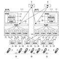
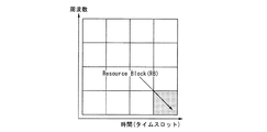
図1は、本発明の第1実施形態に係るセルラ移動通信システムの構成を示すブロック図である。本実施形態では、セルラ移動通信システムの多元接続方式としてOFDMAを用いる。図2は、本実施形態に係るOFDMA方式における無線リソースの概念図である。図2において、横軸はタイムスロット単位での時間、縦軸は周波数(サブキャリア単位)を示す。無線リソースの割当単位であるリソースブロック(Resource Block:RB)は、無線リソースの周波数成分として複数のサブキャリアと、無線リソースの時間成分として複数のOFDMシンボルとから構成される。例えば、LTE(Long Term Evolution)システムでは、12個のサブキャリアと7個のOFDMシンボルから1個のRBが構成される。移動局4には、RB単位で無線リソースが割り当てられる。
[First Embodiment]
FIG. 1 is a block diagram showing a configuration of a cellular mobile communication system according to the first embodiment of the present invention. In this embodiment, OFDMA is used as a multiple access method of a cellular mobile communication system. FIG. 2 is a conceptual diagram of radio resources in the OFDMA scheme according to the present embodiment. In FIG. 2, the horizontal axis represents time in time slot units, and the vertical axis represents frequency (subcarrier units). A resource block (RB), which is a radio resource allocation unit, includes a plurality of subcarriers as frequency components of radio resources and a plurality of OFDM symbols as time components of radio resources. For example, in an LTE (Long Term Evolution) system, one RB is composed of 12 subcarriers and 7 OFDM symbols. Radio resources are allocated to the
図1において、セルラ移動通信システムは、基地局ユニット1−1,1−2(以下、特に区別しないときは「基地局ユニット1」と称する)と、リモート無線部2−1〜6(以下、特に区別しないときは「リモート無線部2」と称する)を有する。
1, cellular mobile communication systems include base station units 1-1 and 1-2 (hereinafter referred to as “
リモート無線部2は、アンテナ30と該アンテナ30を介して無線信号を送受する無線部とを有し(いずれも図示せず)、移動局4との間で無線信号の送受信を行う。リモート無線部2は、セル毎に設けられる。図1の例では、1つのセルに対してリモート無線部2が2つずつ設けられている。具体的には、セル3Aに対してリモート無線部2−1,2−2、セル3Bに対してリモート無線部2−3,2−4、セル3Cに対してリモート無線部2−5,2−6、がそれぞれ設けられている。
The
基地局ユニット1は、複数のリモート無線部2を用いて、移動局4とMIMO技術を用いた通信を行う。MIMO技術を用いた通信(MIMO通信)の方法としては、例えば、最大比合成送信ダイバーシチ等の送信ダイバーシチ、時空間符号、及び、固有ビーム空間多重方式等の空間多重、並びに、それらの組合せがある。
The
基地局ユニット1は、複数のリモート無線部2に接続されている。基地局ユニット1とリモート無線部2の間は、光ファイバケーブル等の通信ケーブルで接続される。この構成は、RRH(Remote Radio Head)と呼ばれる。なお、基地局ユニット1は、それぞれ異なる場所に設置されてもよく、或いは、複数が同じ場所に設置されてもよい。
The
基地局ユニット1は、隣接するセルの組合せ毎に設けられる。図1の例では、基地局ユニット1−1は、隣接するセル3A,3Bの4つのリモート無線部2−1〜4と光ファイバケーブルでそれぞれ接続されている。基地局ユニット1−2は、隣接するセル3B,3Cの4つのリモート無線部2−3〜6と光ファイバケーブルでそれぞれ接続されている。
The
基地局ユニット1は、制御部11と転送部12とベースバンド処理部13を有する。制御部11は、スケジューリング等の基地局制御、及び、隣接するセル間で協調したMIMO通信を行うための制御を行う。制御部11は転送部12と接続される。転送部12は、ユーザデータ及び制御データの転送、並びに、各データのスイッチングを行う。転送部12はベースバンド処理部13と接続される。ベースバンド処理部13は、リモート無線部2の各各に対応して設けられる。ベースバンド処理部13は、対応するリモート無線部2と光ファイバケーブルで接続される。
The
転送部12は、サービングゲートウェイ(Serving Gateway:S−GW)5及びモビリティ・マネジメント装置(Mobility Management entity:MME)6に接続される。S−GW5は、コアネットワークに設置されており、コアネットワークと移動局4との間で送受されるユーザデータの転送およびルーティングを行う。MME6は、移動局4のモビリティ管理およびセッション管理を行う。
The
制御部11は、リモート無線制御部21とタイミング把握部22を有する。タイミング把握部22は、特定のリモート無線部2を使用可能な期間を特定する。
The
例えば図1において、基地局ユニット1−1は、4つのリモート無線部2−1〜4を使用可能であるが、リモート無線部2−1〜4をどのタイムスロットで使用してもよいのかが予め定められている。同様に、基地局ユニット1−2は、4つのリモート無線部2−3〜6を使用可能であるが、リモート無線部2−3〜6をどのタイムスロットで使用してもよいのかが予め定められている。このとき、複数の基地局ユニット1−1,1−2が使用可能なリモート無線部2−3,2−4については、複数の基地局ユニット1−1,1−2が時分割で使用するように、基地局ユニット1−1,1−2に対して使用可能なタイムスロットの割当が行われる。タイミング把握部22は、予め定められたタイムスロット割当情報に基づいて、自基地局ユニット1が各リモート無線部2を使用可能なタイムスロットを特定する。なお、基地局ユニット1間では、時間の同期が取られている。
For example, in FIG. 1, the base station unit 1-1 can use four remote radio units 2-1 to 4, but in which time slot the remote radio units 2-1 to 4 can be used. It is predetermined. Similarly, the base station unit 1-2 can use four remote radio units 2-3 to 6, but it is determined in advance in which time slot the remote radio units 2-3 to 6 may be used. It has been. At this time, for the remote radio units 2-3 and 2-4 that can be used by the plurality of base station units 1-1 and 1-2, the plurality of base station units 1-1 and 1-2 are used in a time division manner. In this manner, usable time slots are allocated to the base station units 1-1 and 1-2. The
リモート無線制御部21は、タイミング把握部22が特定した期間(タイムスロット)に、該当するリモート無線部2を用いてMIMO通信を行う制御を行う。
The remote
図3は、本実施形態に係るセル間協調通信の例である。図3の例では、セル3Aに対してリモート無線部2−1,2−2、セル3Bに対してリモート無線部2−3,2−4、セル3Cに対してリモート無線部2−5,2−6、がそれぞれ設けられている。そして、基地局ユニット1−1は、隣接するセル3A,3Bの4つのリモート無線部2−1〜4と光ファイバケーブルでそれぞれ接続されている。基地局ユニット1−2は、隣接するセル3B,3Cの4つのリモート無線部2−3〜6と光ファイバケーブルでそれぞれ接続されている。基地局ユニット1−3は、隣接するセル3A,3Cの4つのリモート無線部2−1,2−2,2−5,2−6と光ファイバケーブルでそれぞれ接続されている。
FIG. 3 is an example of inter-cell cooperative communication according to the present embodiment. In the example of FIG. 3, remote radio units 2-1 and 2-2 for the cell 3A, remote radio units 2-3 and 2-4 for the
基地局ユニット1−1は、隣接するセル3A,3Bの境界に位置する移動局4に対し、リモート無線部2−1,2−2とリモート無線部2−3,2−4とを用いてMIMO通信を行う。基地局ユニット1−2は、隣接するセル3B,3Cの境界に位置する移動局4に対し、リモート無線部2−3,2−4とリモート無線部2−5,2−6とを用いてMIMO通信を行う。基地局ユニット1−3は、隣接するセル3A,3Cの境界に位置する移動局4に対し、リモート無線部2−1,2−2とリモート無線部2−5,2−6とを用いてMIMO通信を行う。
The base station unit 1-1 uses the remote radio units 2-1 and 2-2 and the remote radio units 2-3 and 2-4 for the
リモート無線部2−1,2−2は、基地局ユニット1−1,1−3によって時分割で使用される。リモート無線部2−3,2−4は、基地局ユニット1−1,1−2によって時分割で使用される。リモート無線部2−5,2−6は、基地局ユニット1−2,1−3によって時分割で使用される。 The remote radio units 2-1 and 2-2 are used in a time division manner by the base station units 1-1 and 1-3. The remote radio units 2-3 and 2-4 are used in a time division manner by the base station units 1-1 and 1-2. The remote radio units 2-5 and 2-6 are used in a time division manner by the base station units 1-2 and 1-3.
図4は、図3に示す基地局ユニット1−1,1−2,1−3に対するタイムスロット割当例である。図4において、基地局ユニット1−1に対してリモート無線部2−1,2−2,2−3,2−4を使用可能なタイムスロットが、基地局ユニット1−2に対してリモート無線部2−3,2−4,2−5,2−6を使用可能なタイムスロットが、基地局ユニット1−3に対してリモート無線部2−1,2−2,2−5,2−6を使用可能なタイムスロットが、それぞれ割り当てられている。基地局ユニット1−1,1−2,1−3は、自己に割り当てられたタイムスロットにおいて、該当するリモート無線部を使用する。なお、基地局ユニット1−1はセル3Cの制御を行わない。そのため、基地局ユニット1−1に割り当てられたタイムスロットにおいて、基地局ユニット1−2あるいは基地局ユニット1−3がリモート無線部2−5,2−6のみを用いてセル3Cに在圏する移動局と通信を行っても良い。同様に、基地局ユニット1−2に割り当てられたタイムスロットにおいて、基地局ユニット1−1あるいは基地局ユニット1−3がリモート無線部2−1,2−2のみを用いてセル3Aに在圏する移動局と通信を行っても良い。同様に、基地局ユニット1−3に割り当てられたタイムスロットにおいて、基地局ユニット1−1あるいは基地局ユニット1−2がリモート無線部2−3,2−4のみを用いてセル3Bに在圏する移動局と通信を行っても良い。
FIG. 4 is an example of time slot allocation for the base station units 1-1, 1-2, and 1-3 shown in FIG. In FIG. 4, the time slot in which the remote radio units 2-1, 2-2, 2-3 and 2-4 can be used for the base station unit 1-1 Time slots in which the units 2-3, 2-4, 2-5, and 2-6 can be used are remote radio units 2-1, 2-2, 2-5, 2 to the base station unit 1-3. Each time slot that can use 6 is assigned. The base station units 1-1, 1-2, and 1-3 use the corresponding remote radio units in the time slots assigned to themselves. The base station unit 1-1 does not control the
なお、例えば、基地局ユニット1−1がリモート無線部2−3,2−4を使用するタイムスロットにおいて、基地局ユニット1−2は、セル3Bに在圏する移動局4から送信される情報を全てドロップしたり、或いは、セル3Bに在圏する移動局4から送信される情報から無線環境やセル3Bに在圏する移動局数などの情報を取得したりするようにしてもよい。
For example, in a time slot in which the base station unit 1-1 uses the remote radio units 2-3 and 2-4, the base station unit 1-2 transmits information transmitted from the
図5は、本実施形態に係るセル間協調通信の他の例である。図5の例では、隣接する3つのセル間で協調したMIMO通信を行う。基地局ユニット1は、時分割のグループとして6つ(#1〜#6)に分類される。このグループ分けは、基地局ユニット1において、あるリモート無線部に対する制御が同一タイムスロットで重複しないように行われる。基地局ユニット1は、隣接する3つのセルに対応するリモート無線部2と接続される。
FIG. 5 is another example of inter-cell cooperative communication according to the present embodiment. In the example of FIG. 5, cooperative MIMO communication is performed between three adjacent cells. The
図6は、図5に示す6つの時分割グループ#1〜#6のタイムスロット割当例である。各時分割グループ#1〜#6に属する基地局ユニット1は、自時分割グループに割り当てられたタイムスロットにおいて、自己と接続するリモート無線部2(隣接する3つのセルに対応するリモート無線部2)を使用する。
FIG. 6 is an example of time slot allocation for the six time
なお、1基地局ユニットで制御を行う隣接するセルの組合せは、セル配置に応じて適宜、変更可能であり、上述した2つのセルの組合せ又は3つのセルの組合せに限定されない。例えば、隣接する4つのセルの組合せ毎に基地局ユニット1を設けるようにしてもよい。この場合、基地局ユニット1を4つの時分割グループに分類することによって、基地局ユニット1において、あるリモート無線部に対する制御が同一タイムスロットで重複しないように、隣接する4つのセル間で協調したMIMO通信を行うことができる。
Note that the combination of adjacent cells controlled by one base station unit can be appropriately changed according to the cell arrangement, and is not limited to the combination of the two cells or the combination of the three cells described above. For example, the
又、1基地局ユニットで制御を行う隣接セル数に対して、異なる数のセルの組合せを同時に適用することも可能である。例えば、隣接する2つのセルの組合せと隣接する3つのセルの組合せとを同時に適用する場合、基地局ユニット1を15個の時分割グループに分類することによって、基地局ユニット1において、あるリモート無線部に対する制御を同一タイムスロットで重複させることなく、隣接する2つのセル間および隣接する3つのセル間で協調したMIMO通信を行うことができる。
It is also possible to simultaneously apply different numbers of cell combinations to the number of adjacent cells controlled by one base station unit. For example, when applying a combination of two adjacent cells and a combination of three adjacent cells at the same time, the
なお、基地局ユニット1は、セル境界に位置する移動局4に対し、セル間で協調したMIMO通信を行うか否かを選択するようにしてもよい。例えば、隣接する3つのセル間で協調したMIMO通信を行うことができる場合には、セル間で協調したMIMO通信を行わない(第1の通信方法)、2つのセル間で協調したMIMO通信を行う(第2の通信方法)、3つのセル間で協調したMIMO通信を行う(第3の通信方法)の中から、適切な通信方法を選択するようにしてもよい。
Note that the
[第2実施形態]
図7は、本発明の第2実施形態に係るセルラ移動通信システムの構成を示すブロック図である。この図7において図1の各部に対応する部分には同一の符号を付け、その説明を省略する。第2実施形態では、複数の基地局ユニット1が一つのリモート無線部2を周波数分割で使用する。
[Second Embodiment]
FIG. 7 is a block diagram showing a configuration of a cellular mobile communication system according to the second embodiment of the present invention. In FIG. 7, parts corresponding to those in FIG. 1 are denoted by the same reference numerals, and description thereof is omitted. In the second embodiment, a plurality of
図7に示す基地局ユニット1において、ベースバンド処理部13は、自己と接続するリモート無線部2に対して使用可能な周波数帯(サブキャリア)のみを用いる。リモート無線制御部21は、自基地局ユニット1と接続するリモート無線部2の使用可能な周波数帯を用いてMIMO通信を行う制御を行う。各基地局ユニット1に対して、各リモート無線部2の使用可能な周波数帯が予め定められる。
In the
図8は、図7に示すセル3Bに対応するリモート無線部2−3,2−4を使用する基地局ユニット1−1,1−2に対する周波数帯割当例である。図8において、基地局ユニット1−1,1−2に対し、リモート無線部2−3,2−4の使用可能な周波数帯がそれぞれ割り当てられている。基地局ユニット1−1,1−2は、自己に割り当てられた周波数帯において、リモート無線部2−3,2−4を使用する。
FIG. 8 is an example of frequency band allocation for the base station units 1-1 and 1-2 using the remote radio units 2-3 and 2-4 corresponding to the
なお、図7ではリモート無線部2−1,2−2は基地局ユニット1−1とのみ、リモート無線部2−5,2−6は基地局ユニット1−2とのみ接続している。したがって、リモート無線部2−1,2−2のみを用いて通信を行う移動局に対して、および、リモート無線部2−5,2−6のみを用いて通信を行う移動局に対しては、全周波数帯を用いて無線リソース割当を行うことができる。 In FIG. 7, the remote radio units 2-1 and 2-2 are connected only to the base station unit 1-1, and the remote radio units 2-5 and 2-6 are connected only to the base station unit 1-2. Therefore, for mobile stations that communicate using only the remote radio units 2-1 and 2-2, and for mobile stations that communicate using only the remote radio units 2-5 and 2-6. Radio resource allocation can be performed using the entire frequency band.
又、第2実施形態においても第1実施形態と同様に図5の構成をとることができる。 In the second embodiment, the configuration shown in FIG. 5 can be adopted as in the first embodiment.
又、図8の例では、周波数帯域を単純に2つに分割しているが、周波数選択性の影響を低減させるために、ランダムにサブキャリアを選択して、各基地局ユニット1に割り当てるサブチャネルを構成するようにしてもよい。
In the example of FIG. 8, the frequency band is simply divided into two. However, in order to reduce the influence of frequency selectivity, subcarriers are randomly selected and assigned to each
又、上述した第2実施形態では多元接続方式としてOFDMA方式を用いているが、移動局に対してサブキャリア単位の無線リソース割当を行わない多元接続方式にも適用可能である。この場合、図7に示す基地局ユニット1において、ベースバンド処理部13は、自己と接続するリモート無線部2で使用可能な周波数帯に送信信号を変換する信号周波数変換機能と、該リモート無線部2が受信した信号から該使用可能な周波数帯の受信信号を取得する周波数信号分離機能とを有するように構成する。
In the second embodiment described above, the OFDMA scheme is used as the multiple access scheme, but the present invention is also applicable to a multiple access scheme in which radio resources are not allocated to the mobile station in units of subcarriers. In this case, in the
上述した実施形態によれば、任意のセル境界に位置する移動局に対して、隣接するセル間で協調した通信方法を適用することができる。これにより、セル境界に位置する移動局にとって最適な通信方法を適用することが可能となり、通信品質の向上を図ることができる。 According to the above-described embodiment, a communication method coordinated between adjacent cells can be applied to a mobile station located at an arbitrary cell boundary. This makes it possible to apply a communication method that is optimal for a mobile station located at a cell boundary, and to improve communication quality.
以上、本発明の実施形態について図面を参照して詳述してきたが、具体的な構成はこの実施形態に限られるものではなく、本発明の要旨を逸脱しない範囲の設計変更等も含まれる。 As mentioned above, although embodiment of this invention was explained in full detail with reference to drawings, the specific structure is not restricted to this embodiment, The design change etc. of the range which does not deviate from the summary of this invention are included.
1−1,1−2…基地局ユニット、2−1〜6…リモート無線部、3A,3B,3C…セル、4…移動局、11…制御部、12…転送部、13…ベースバンド処理部、21…リモート無線制御部、22…タイミング把握部、30…アンテナ 1-1, 1-2: base station unit, 2-1-6: remote radio unit, 3A, 3B, 3C ... cell, 4 ... mobile station, 11 ... control unit, 12 ... transfer unit, 13 ... baseband processing Part, 21 ... remote radio control part, 22 ... timing grasping part, 30 ... antenna
Claims (5)
アンテナと前記アンテナを介して無線信号を送受する無線部とを有する前記遠隔無線装置をセル毎に設け、
複数の前記遠隔無線装置を用いて移動局とMIMO通信を行う前記基地局ユニットを、隣接するセルの組合せ毎に設け、
セル毎に設けられた各前記遠隔無線装置は、自己のセルに対して設けられた複数の前記基地局ユニットにより共用される、
ことを特徴とするセルラ移動通信システム。 In a cellular mobile communication system, comprising: a base station unit; and a remote radio device disposed remotely from the base station unit and connected to the base station unit,
Provided the remote radio apparatus and a radio unit for transmitting and receiving radio signals via the antenna and the antenna for each cell,
It provided the base station unit for mobile station and MIMO communication using a plurality of the remote radio apparatus, for each combination of adjacent cells,
Each of the remote radio devices provided for each cell is shared by a plurality of the base station units provided for its own cell.
A cellular mobile communication system.
特定の前記遠隔無線装置を使用可能な期間を特定するタイミング把握部と、
該特定された期間に該遠隔無線装置を用いてMIMO通信を行う制御を行う遠隔無線制御部と、を備え、
セル毎に設けられた各前記遠隔無線装置は、自己のセルに対して設けられた複数の前記基地局ユニットにより時分割で使用されるセルラ移動通信システムであり、
第1の前記基地局ユニットに割り当てられた前記期間において、前記第1の基地局ユニットの前記隣接するセルの組合せに含まれる一部のセルに対して設けられた第2の前記基地局ユニットが、前記第1の基地局ユニットの前記隣接するセルの組合せに含まれるセル以外であって前記第2の前記基地局ユニットの前記隣接するセルの組合せに含まれるセルの前記遠隔無線装置を用いて移動局と通信を行う、
ことを特徴とする請求項1に記載のセルラ移動通信システム。 The base station unit is
A timing grasping unit that specifies a time period available for certain of the remote wireless device,
A remote radio control unit that performs control to perform MIMO communication using the remote radio device during the specified period,
Each of the remote radio devices provided for each cell is a cellular mobile communication system used in a time division manner by a plurality of the base station units provided for its own cell,
In the period allocated to the first base station unit, the second base station unit provided for a part of cells included in the combination of the adjacent cells of the first base station unit is Using the remote radio apparatus of a cell other than a cell included in the adjacent cell combination of the first base station unit and included in the adjacent cell combination of the second base station unit Communicate with mobile stations,
The cellular mobile communication system according to claim 1.
特定の前記遠隔無線装置を使用可能な期間を特定するタイミング把握部と、
該特定された期間に該遠隔無線装置を用いてMIMO通信を行う制御を行う遠隔無線制御部と、を備え、
セル毎に設けられた各前記遠隔無線装置は、自己のセルに対して設けられた複数の前記基地局ユニットにより時分割で使用されるセルラ移動通信システムであり、
第1の前記基地局ユニットに割り当てられた前記期間において、前記第1の基地局ユニットの前記隣接するセルの組合せに含まれる一部のセルに対して設けられた第2の前記基地局ユニットが、当該期間に対応する前記特定の遠隔無線装置のセルに在圏する移動局から送信される情報から、無線環境または当該期間に対応する前記特定の遠隔無線装置のセルに在圏する移動局数の情報を取得する、
ことを特徴とする請求項1に記載のセルラ移動通信システム。 The base station unit is
A timing grasping unit that specifies a time period available for certain of the remote wireless device,
A remote radio control unit that performs control to perform MIMO communication using the remote radio device during the specified period,
Each of the remote radio devices provided for each cell is a cellular mobile communication system used in a time division manner by a plurality of the base station units provided for its own cell,
In the period allocated to the first base station unit, the second base station unit provided for a part of cells included in the combination of the adjacent cells of the first base station unit is From the information transmitted from the mobile station residing in the cell of the specific remote radio apparatus corresponding to the period, the number of mobile stations residing in the cell of the specific remote radio apparatus corresponding to the period from the information transmitted from the mobile station Get information on,
The cellular mobile communication system according to claim 1.
特定の前記遠隔無線装置を使用可能な期間を特定するタイミング把握部と、
該特定された期間に該遠隔無線装置を用いてMIMO通信を行う制御を行う遠隔無線制御部と、を備え、
セル毎に設けられた各前記遠隔無線装置は、自己のセルに対して設けられた複数の前記基地局ユニットにより時分割で使用されるセルラ移動通信システムであり、
前記基地局ユニットから構成される時分割グループ毎に同じ前記期間が割り当てられ、
前記時分割グループは、ある前記遠隔無線装置に対する前記基地局ユニットからの制御が同じ前記期間で他の前記基地局ユニットと重複しないように決められている、
ことを特徴とする請求項1に記載のセルラ移動通信システム。 The base station unit is
A timing grasping unit that specifies a time period available for certain of the remote wireless device,
A remote radio control unit that performs control to perform MIMO communication using the remote radio device during the specified period,
Each of the remote radio devices provided for each cell is a cellular mobile communication system used in a time division manner by a plurality of the base station units provided for its own cell,
The same period is assigned to each time division group composed of the base station units,
The time division group is determined so that control from the base station unit for a certain remote radio apparatus does not overlap with other base station units in the same period.
The cellular mobile communication system according to claim 1.
特定の前記遠隔無線装置で使用可能な周波数帯を用いてMIMO通信を行う制御を行う遠隔無線制御部を備え、
セル毎に設けられた各前記遠隔無線装置は、自己のセルに対して設けられた複数の前記基地局ユニットにより周波数分割で使用される、
ことを特徴とする請求項1に記載のセルラ移動通信システム。 The base station unit is
Comprising a remote radio control unit that performs control for performing MIMO communication using a frequency band available for a particular said remote wireless device,
Each remote radio device provided for each cell is used in frequency division by a plurality of the base station units provided for its own cell,
The cellular mobile communication system according to claim 1.
Priority Applications (1)
| Application Number | Priority Date | Filing Date | Title |
|---|---|---|---|
| JP2010178703A JP5582471B2 (en) | 2010-08-09 | 2010-08-09 | Cellular mobile communication system |
Applications Claiming Priority (1)
| Application Number | Priority Date | Filing Date | Title |
|---|---|---|---|
| JP2010178703A JP5582471B2 (en) | 2010-08-09 | 2010-08-09 | Cellular mobile communication system |
Publications (2)
| Publication Number | Publication Date |
|---|---|
| JP2012039447A JP2012039447A (en) | 2012-02-23 |
| JP5582471B2 true JP5582471B2 (en) | 2014-09-03 |
Family
ID=45850921
Family Applications (1)
| Application Number | Title | Priority Date | Filing Date |
|---|---|---|---|
| JP2010178703A Active JP5582471B2 (en) | 2010-08-09 | 2010-08-09 | Cellular mobile communication system |
Country Status (1)
| Country | Link |
|---|---|
| JP (1) | JP5582471B2 (en) |
Families Citing this family (1)
| Publication number | Priority date | Publication date | Assignee | Title |
|---|---|---|---|---|
| JP6952255B2 (en) * | 2016-10-26 | 2021-10-20 | パナソニックIpマネジメント株式会社 | Wireless communication system |
Family Cites Families (3)
| Publication number | Priority date | Publication date | Assignee | Title |
|---|---|---|---|---|
| FI105960B (en) * | 1996-12-04 | 2000-10-31 | Nokia Networks Oy | Cellular radio system |
| JP4852984B2 (en) * | 2005-11-09 | 2012-01-11 | 株式会社日立製作所 | Multi-channel transmission system using multiple base stations |
| JP4842038B2 (en) * | 2006-07-19 | 2011-12-21 | 三菱電機株式会社 | Communications system |
-
2010
- 2010-08-09 JP JP2010178703A patent/JP5582471B2/en active Active
Also Published As
| Publication number | Publication date |
|---|---|
| JP2012039447A (en) | 2012-02-23 |
Similar Documents
| Publication | Publication Date | Title |
|---|---|---|
| USRE48396E1 (en) | Method and system for dynamic cell configuration | |
| JP5303784B2 (en) | Wireless communication system | |
| JP7288116B2 (en) | Systems and methods for communicating orthogonal frequency division multiplexing (OFDM) frame formats | |
| US20130279452A1 (en) | Frequency domain transmission method and apparatus | |
| US20210152272A1 (en) | Transmitting apparatus, receiving apparatus, method, and recording medium | |
| AU2019200838B2 (en) | Systems and methods for mapping virtual radio instances into physical volumes of coherence in distributed antenna wireless systems | |
| JP5582471B2 (en) | Cellular mobile communication system |
Legal Events
| Date | Code | Title | Description |
|---|---|---|---|
| A621 | Written request for application examination |
Free format text: JAPANESE INTERMEDIATE CODE: A621 Effective date: 20130308 |
|
| A521 | Request for written amendment filed |
Free format text: JAPANESE INTERMEDIATE CODE: A821 Effective date: 20130311 |
|
| A521 | Request for written amendment filed |
Free format text: JAPANESE INTERMEDIATE CODE: A821 Effective date: 20130308 |
|
| A977 | Report on retrieval |
Free format text: JAPANESE INTERMEDIATE CODE: A971007 Effective date: 20140115 |
|
| A131 | Notification of reasons for refusal |
Free format text: JAPANESE INTERMEDIATE CODE: A131 Effective date: 20140121 |
|
| A521 | Request for written amendment filed |
Free format text: JAPANESE INTERMEDIATE CODE: A523 Effective date: 20140320 |
|
| A521 | Request for written amendment filed |
Free format text: JAPANESE INTERMEDIATE CODE: A821 Effective date: 20140324 |
|
| TRDD | Decision of grant or rejection written | ||
| A01 | Written decision to grant a patent or to grant a registration (utility model) |
Free format text: JAPANESE INTERMEDIATE CODE: A01 Effective date: 20140610 |
|
| A61 | First payment of annual fees (during grant procedure) |
Free format text: JAPANESE INTERMEDIATE CODE: A61 Effective date: 20140707 |
|
| R150 | Certificate of patent or registration of utility model |
Ref document number: 5582471 Country of ref document: JP Free format text: JAPANESE INTERMEDIATE CODE: R150 |
|
| R250 | Receipt of annual fees |
Free format text: JAPANESE INTERMEDIATE CODE: R250 |
|
| R250 | Receipt of annual fees |
Free format text: JAPANESE INTERMEDIATE CODE: R250 |
|
| R250 | Receipt of annual fees |
Free format text: JAPANESE INTERMEDIATE CODE: R250 |