JP5582008B2 - Vehicle information transmission device - Google Patents
Vehicle information transmission device Download PDFInfo
- Publication number
- JP5582008B2 JP5582008B2 JP2010273883A JP2010273883A JP5582008B2 JP 5582008 B2 JP5582008 B2 JP 5582008B2 JP 2010273883 A JP2010273883 A JP 2010273883A JP 2010273883 A JP2010273883 A JP 2010273883A JP 5582008 B2 JP5582008 B2 JP 5582008B2
- Authority
- JP
- Japan
- Prior art keywords
- light source
- light
- driver
- vehicle
- virtual image
- Prior art date
- Legal status (The legal status is an assumption and is not a legal conclusion. Google has not performed a legal analysis and makes no representation as to the accuracy of the status listed.)
- Active
Links
- 230000005540 biological transmission Effects 0.000 title claims description 47
- 238000012790 confirmation Methods 0.000 claims description 11
- 238000000034 method Methods 0.000 claims description 7
- 230000001737 promoting effect Effects 0.000 claims description 5
- 238000010586 diagram Methods 0.000 description 37
- 238000009792 diffusion process Methods 0.000 description 28
- 235000019557 luminance Nutrition 0.000 description 20
- 239000004973 liquid crystal related substance Substances 0.000 description 12
- 238000009826 distribution Methods 0.000 description 11
- 239000005357 flat glass Substances 0.000 description 11
- 238000004891 communication Methods 0.000 description 3
- 230000004438 eyesight Effects 0.000 description 3
- 230000001678 irradiating effect Effects 0.000 description 2
- 230000005043 peripheral vision Effects 0.000 description 2
- 230000003945 visual behavior Effects 0.000 description 2
- 241000282412 Homo Species 0.000 description 1
- 206010021033 Hypomenorrhoea Diseases 0.000 description 1
- 239000004743 Polypropylene Substances 0.000 description 1
- 230000001133 acceleration Effects 0.000 description 1
- 239000003086 colorant Substances 0.000 description 1
- 230000003247 decreasing effect Effects 0.000 description 1
- 238000001514 detection method Methods 0.000 description 1
- 239000011521 glass Substances 0.000 description 1
- 210000004394 hip joint Anatomy 0.000 description 1
- 238000004519 manufacturing process Methods 0.000 description 1
- 239000000463 material Substances 0.000 description 1
- 238000005259 measurement Methods 0.000 description 1
- 230000003287 optical effect Effects 0.000 description 1
- 239000013307 optical fiber Substances 0.000 description 1
- 239000004417 polycarbonate Substances 0.000 description 1
- 229920000515 polycarbonate Polymers 0.000 description 1
- 229920001155 polypropylene Polymers 0.000 description 1
- 230000000638 stimulation Effects 0.000 description 1
- 238000003860 storage Methods 0.000 description 1
- 230000001629 suppression Effects 0.000 description 1
- 230000000007 visual effect Effects 0.000 description 1
- 230000002618 waking effect Effects 0.000 description 1
Images


Classifications
-
- G—PHYSICS
- G08—SIGNALLING
- G08G—TRAFFIC CONTROL SYSTEMS
- G08G1/00—Traffic control systems for road vehicles
- G08G1/16—Anti-collision systems
-
- B—PERFORMING OPERATIONS; TRANSPORTING
- B60—VEHICLES IN GENERAL
- B60K—ARRANGEMENT OR MOUNTING OF PROPULSION UNITS OR OF TRANSMISSIONS IN VEHICLES; ARRANGEMENT OR MOUNTING OF PLURAL DIVERSE PRIME-MOVERS IN VEHICLES; AUXILIARY DRIVES FOR VEHICLES; INSTRUMENTATION OR DASHBOARDS FOR VEHICLES; ARRANGEMENTS IN CONNECTION WITH COOLING, AIR INTAKE, GAS EXHAUST OR FUEL SUPPLY OF PROPULSION UNITS IN VEHICLES
- B60K35/00—Arrangement of adaptations of instruments
-
- B60K35/28—
-
- B60K35/29—
-
- B60K35/60—
-
- G—PHYSICS
- G02—OPTICS
- G02B—OPTICAL ELEMENTS, SYSTEMS OR APPARATUS
- G02B27/00—Optical systems or apparatus not provided for by any of the groups G02B1/00 - G02B26/00, G02B30/00
- G02B27/01—Head-up displays
-
- G—PHYSICS
- G08—SIGNALLING
- G08G—TRAFFIC CONTROL SYSTEMS
- G08G1/00—Traffic control systems for road vehicles
- G08G1/16—Anti-collision systems
- G08G1/166—Anti-collision systems for active traffic, e.g. moving vehicles, pedestrians, bikes
-
- G—PHYSICS
- G08—SIGNALLING
- G08G—TRAFFIC CONTROL SYSTEMS
- G08G1/00—Traffic control systems for road vehicles
- G08G1/16—Anti-collision systems
- G08G1/167—Driving aids for lane monitoring, lane changing, e.g. blind spot detection
-
- B60K2360/179—
-
- B60K2360/188—
-
- B60K2360/334—
-
- G—PHYSICS
- G02—OPTICS
- G02B—OPTICAL ELEMENTS, SYSTEMS OR APPARATUS
- G02B27/00—Optical systems or apparatus not provided for by any of the groups G02B1/00 - G02B26/00, G02B30/00
- G02B27/01—Head-up displays
- G02B27/0101—Head-up displays characterised by optical features
- G02B2027/014—Head-up displays characterised by optical features comprising information/image processing systems
Landscapes
- Physics & Mathematics (AREA)
- General Physics & Mathematics (AREA)
- Engineering & Computer Science (AREA)
- Chemical & Material Sciences (AREA)
- Combustion & Propulsion (AREA)
- Transportation (AREA)
- Mechanical Engineering (AREA)
- Optics & Photonics (AREA)
- Instrument Panels (AREA)
- Traffic Control Systems (AREA)
- Radar Systems Or Details Thereof (AREA)
- Fittings On The Vehicle Exterior For Carrying Loads, And Devices For Holding Or Mounting Articles (AREA)
Description
本発明は車両用情報伝達装置に関する。 The present invention relates to a vehicle information transmission device.
特許文献1には、LEDの光をフロントウインドウガラスに反射させて運転者に情報を伝達する車両用表示装置が開示されている。特許文献2には、車両の左右に障害物を検出すると左右の警告表示の大きさまたは輝度を個別に変更させる車両の障害物警報装置が開示されている。特許文献3には、車両に設置した光源の光を、検出した車外の危険の位置に対応づくフロントガラス面上の位置に映りこむように照射することで、運転者に危険を知らせる車両用運転支援システムが開示されている。
しかしながら、特許文献1から3によれば、情報伝達の仕方について改善の余地が残されているという問題点があった。
However, according to
本発明は、上記の事情に鑑みてなされたものであって、運転者にとってより良い情報伝達を実現することができる車両用情報伝達装置を提供することを目的とする。 The present invention has been made in view of the above circumstances, and an object thereof is to provide a vehicle information transmission device that can realize better information transmission for a driver.
本発明は、或る対象の認識を促す車両用情報伝達装置であって、前記或る対象の位置とは異なる位置の認識を促すこと、を特徴とする。なお、前記或る対象の位置と前記異なる位置とは、互いに離間した位置であるという構成としても良い。また、前記或る対象の認識の促し方と前記異なる位置の認識の促し方とは異なるという構成としても良い。また、前記或る対象の位置が運転者から見て左側の場合には、前記異なる位置は前記運転者から見て右側であり、前記或る対象の位置が前記運転者から見て右側の場合には、前記異なる位置は前記運転者から見て左側であるという構成としても良い。また、前記或る対象の認識を促している最中に、前記異なる位置の認識を促すという構成としても良い。 The present invention is an information transmission device for a vehicle that promotes recognition of a certain target, and is characterized by prompting recognition of a position different from the position of the certain target. Note that the certain target position and the different position may be separated from each other. Further, the method for promoting recognition of a certain object may be different from the method for promoting recognition of the different position. Further, when the position of the certain object is on the left side when viewed from the driver, the different position is on the right side when viewed from the driver, and when the position of the certain object is on the right side when viewed from the driver Alternatively, the different position may be on the left side when viewed from the driver. Further, it may be configured such that the recognition of the different position is promoted while the recognition of the certain object is promoted.
本発明は、運転者から見て右側の確認を促す第一の表示部と前記運転者から見て左側の確認を促す第二の表示部とを有し、或る対象の確認を前記右側または前記左側で促す場合には、前記第一の表示部および前記第二の表示部のそれぞれで、前記右側および前記左側の確認を促すこと、を特徴とする。本発明は、フロントウインドシールドまたはリアウインドシールドにおける複数の位置に虚像を表示する表示手段を有し、前記表示手段は、或る対象の認識を運転者に促すために、或る位置に虚像を表示する場合には、当該或る位置とは異なる位置にも虚像を表示すること、を特徴とする。 The present invention includes a first display unit that prompts confirmation on the right side when viewed from the driver, and a second display unit that prompts confirmation on the left side when viewed from the driver, and confirms a certain object on the right side or the right side. When urging on the left side, confirmation of the right side and the left side is urged in each of the first display unit and the second display unit. The present invention has display means for displaying virtual images at a plurality of positions on the front windshield or the rear windshield, and the display means displays virtual images at a certain position in order to prompt the driver to recognize a certain object. When displaying, a virtual image is displayed at a position different from the certain position.
本発明は、或る対象の認識だけでなく、当該或る対象の位置とは異なる位置の認識も促すので、運転者にとってより良い情報伝達を実現することができるという効果を奏する。 The present invention not only recognizes a certain object but also promotes recognition of a position different from the position of the certain object, so that it is possible to achieve better information transmission for the driver.
以下に、本発明にかかる車両用情報伝達装置を含む車両用情報伝達システムの実施形態を図面に基づいて詳細に説明する。なお、この実施形態により本発明が限定されるものではない。 Hereinafter, an embodiment of a vehicle information transmission system including a vehicle information transmission device according to the present invention will be described in detail with reference to the drawings. In addition, this invention is not limited by this embodiment.
本実施形態にかかる車両用情報伝達システムは、インストルメントパネルにアレイ状(複数行または複数列)に搭載(配列)された複数の光源(LED:light−emitting diode)の光をフロントウインドウガラスに照射して、自車両周辺に在る危険対象(例えば、歩行者、自転車、自動車、および死角など)の存在位置または存在方向を、当該光に因る虚像で運転者に告知(注意喚起または警告)するシステムである。以下では、このシステムの構成およびこのシステムで実行される動作等の一例について、図を参照しながら詳細に説明する。 The vehicle information transmission system according to the present embodiment uses light from a plurality of light-emitting diodes (LEDs) mounted (arranged) in an array (a plurality of rows or a plurality of columns) on an instrument panel on a front window glass. Irradiate and notify the driver of the presence position or direction of dangerous objects around the vehicle (for example, pedestrians, bicycles, cars, blind spots, etc.) with a virtual image due to the light (warning or warning) ) System. Hereinafter, an example of the configuration of the system and the operation executed by the system will be described in detail with reference to the drawings.
なお、以下では、光源の搭載位置を主にインストルメントパネルとして説明するが、例えばメーターパネルなどでもよい。また、光源を主に単色のLEDとして説明するが、例えばフルカラーLEDまたはバルブ等でもよい。また、光の照射先(虚像の表示先)を主にフロントウインドウガラスとして説明するが、例えばAピラー、サイドミラー、メーターパネル、またはインストルメントパネル等でもよい。また、運転者に告知するコンテンツを、主に危険対象(リクス)として説明するが、例えば経路案内、メール着信、運転者の状態・体調(例えば起きている、寝ているなど)、または自車両の状態(例えばエコ運転の状態など)等でもよい。また、危険対象の検知の手段を対物センサとして説明するが、例えば、カメラに因る画像認識、車車間通信または路車間通信などのような通信、またはナビゲーション情報(例えば危険な場所等に関する地図・データベースなど)等でもよい。また、告知を促す位置および方向を、主に運転者から見て左・右として説明するが、例えば運転者から見て前・後等でもよい。また、虚像の表示形状を主に線状の形状(点列)で説明するが、例えばアイコンなどの図形、文字、または記号等でもよい。また、危険対象の存在位置または存在方向を告知する以外にも、当該危険対象の内容(例えば、危険対象が歩行者であるとか、自転車であるとか、自動車であるとか、または死角であるとか、といったこと等)等も告知してもよい。また、告知の態様(告知の形態、告知の仕方)を主に光として説明するが、例えば音(音声)または操作反力など人間が認識可能な態様であればよい。 In the following description, the mounting position of the light source will be mainly described as an instrument panel, but it may be a meter panel, for example. Further, although the light source will be mainly described as a single color LED, for example, a full color LED or a bulb may be used. The light irradiation destination (virtual image display destination) will be mainly described as a front window glass. However, for example, an A pillar, a side mirror, a meter panel, or an instrument panel may be used. In addition, the content to be notified to the driver is mainly described as a risk target (Rix). For example, route guidance, incoming mail, driver's condition / physical condition (for example, waking up, sleeping, etc.), or own vehicle (For example, the state of eco-driving, etc.). Further, although the dangerous object detection means will be described as an objective sensor, for example, image recognition due to a camera, communication such as vehicle-to-vehicle communication or road-to-vehicle communication, or navigation information (for example, a map / Database, etc.). In addition, the position and direction for prompting the notification will be mainly described as left and right when viewed from the driver, but may be, for example, before and after when viewed from the driver. Moreover, although the display shape of a virtual image is mainly described as a linear shape (dot sequence), it may be a graphic such as an icon, a character, a symbol, or the like. In addition to announcing the location or direction of the dangerous object, the contents of the dangerous object (for example, whether the dangerous object is a pedestrian, a bicycle, a car, or a blind spot, Etc.) may also be announced. In addition, the mode of notification (the mode of notification, the method of notification) is mainly described as light, but any mode that can be recognized by humans, such as sound (voice) or operation reaction force, may be used.
〔1.構成〕
図1は、本実施形態にかかる車両用情報伝達システムの構成の一例を示すブロック図である。車両1には、複数の光源10aおよび光源10aの光の透り具合(具体的には光の輝度)を調整する機構を有する光源パネル10と、対物センサ11と、ドライバセンサ12と、車速センサ13と、リスク演算部14aを含むECU(electronic control unit)14と、点灯制御部15と、透過制御部16と、が備えられている。
[1. Constitution〕
FIG. 1 is a block diagram illustrating an example of a configuration of a vehicle information transmission system according to the present embodiment. The
対物センサ11は、車両1周辺の車外環境(例えば、歩行者・自転車・自動車・死角(例えばビルの陰・カーブの向こう側・車両の奥など)などの対象、および直線・左カーブ・右カーブなどの道路形状などに関する情報)を検出する。ドライバセンサ12は、運転者の注視点または注視方向を検出する。車速センサ13は車両1の車速を検出する。リスク演算部14aは、対物センサ11で検出した車両1周辺の車外環境、ドライバセンサ12で検出した注視点または注視方向、および車速センサ13で検出した車速などに基づいて、車両1周辺の危険(リクス)の度合いを演算(推定)する。
The
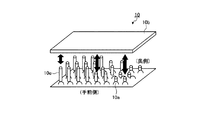
図2は、光源パネル10の構成の一例を示す図である。図2において、符号10bは拡散板であり、符号10cは軸部材であり、符号10dはバネである。光源パネル10には、複数の光源10aが、横方向(左右方向)および縦方向(高さ方向、上下方向)へ光の照射ができるように複数行または複数列のアレイ状に配置される。フロントウインドウガラスに上から順に赤・黄・緑の横3列の虚像を映し出すために、光源パネル10が設置されたときに運転者から見て手前側となる列には赤色系の光を発する光源10aが配置され、真ん中の列には黄色系の光を発する光源10aが配置され、そして奥側の列には緑色系の光を発する光源10aが配置される。光源パネル10には、光源10aの光の透り具合(光のぼけ具合/光の拡散性)を光源10aの位置と紐付けて全体的または部分的に調整するための拡散板10bおよび軸部材10cと、故障時において光源10aと拡散板10bとの距離を最大の状態に維持するための、フェイルセーフの役割を担う複数のバネ10dと、が配置されている。光源パネル10には、拡散板10bのピッチ・ヨー・ロールの3つの回転運動(上下方向・左右方向・捩り方向への運動)を電磁または電気的に実現する、モータのような動力装置(図示せず)が配置されている。拡散板10bは、例えばポリプロピネンまたはポリカーボネートなどの素材で作られた薄い板状の部材である。軸部材10cは、拡散板10bの3つの回転運動の軸となる棒状の部材である。なお、バネ10dの位置または本数は、故障時において光源10aと拡散板10bとの距離を最大の状態に維持することができる位置または本数であればよい。また、光をより広い範囲に拡大するために、拡散板10bの上または下にフレネルレンズを挿入してもよい。
FIG. 2 is a diagram illustrating an example of the configuration of the
図3は、光源パネル10の構成の別の一例を示す図である。図3において、符号10eは導光部材である。光源パネル10には、光源10aの光の透り具合を調整するための拡散板10bおよび導光部材10eが配置されている。導光部材10eは、例えば光ファイバーなどであり、図示の如く個々の光源10aに対して配置される。光源パネル10には、拡散板10bと導光部材10eとの距離の調整を実現する動力装置(図示せず)が配置されている。図3に示すような構成を採ることにより、光源10a毎に独立して光の透り具合を調整することが可能となる。
FIG. 3 is a diagram illustrating another example of the configuration of the
図4は、光源パネル10の構成の別の一例を示す図である。図4において、符号10fは液晶パネルである。光源パネル10には、光源10aの光の透り具合を調整するための液晶パネル10fが、光源10aとの距離が固定された状態で配置される。図4に示すような構成を採ることにより、液晶パネル10fの開口率を中心から周辺に向って小さくして光をぼかすことができる。
FIG. 4 is a diagram illustrating another example of the configuration of the
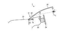
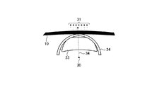
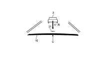
図5は、車両1における光源パネル10の搭載位置の一例を示す図である。図5において、符号20は例えばテーパーガラスなどのような二重写り抑制構造を有するフロントウインドウガラスであり、符号21はボンネットであり、符号22はインストルメントパネルであり、符号23はメーターパネルであり、符号24はステアリングホイールであり、符号30は運転者のアイポイントであり、符号31は光源パネル10からの光に因る虚像であり、符号32はアイポイント30を通過する水平ラインであり、符号33は光源パネル10からの光の光路である。光源パネル10は、インストルメントパネル22に設置されるが、特に、運転者の周辺視野の最下層(例えば、アイポイント30を通過する水平ライン32からの俯角αが5度以下など)で運転者に虚像31を認識させることが可能となる位置に設置される。例えば、光源パネル10は、メーターパネル23よりフロントウインドウガラス20側(換言すると、アイポイント30から見てインストルメントパネル22の奥側)の位置に設置される。ここで、アイポイント30は、図6に示すように、ISO6549−1980に基づいて人体模型を座席に着座させたときの当該人体模型の股関節点であるシーティングレファレンスポイント36の垂直上方635(mm)の高さの点である(ホームページアドレス“http://www.mlit.go.jp/jidosha/kijyun/saimokubetten/saibet_081_00.pdf”で開示されている“道路運送車両の保安基準の細目を定める告示〔2005.11.09〕別添81(直前直差確認鏡の技術基準)”を参照)。
FIG. 5 is a diagram illustrating an example of a mounting position of the
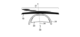
図7および8は、車両1における光源パネル10の搭載位置の別の一例を示す図である。図7および8において、符号25はデフロスタ吹出部である。例えば、光源パネル10は、アイポイント30から見てデフロスタ吹出部25の手前(図7参照)または奥側(図8参照)の位置に設置される。例えば、光源パネル10は、インストルメントパネル22の表面より下(換言すると、インストルメントパネル22の内部)に設置される。例えば、光源パネル10は、インストルメントパネル22に埋め込まれる。
7 and 8 are diagrams illustrating another example of the mounting position of the
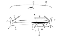
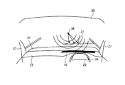
図9は、車両1における光源パネル10の搭載位置の別の一例を示す図である。図9において、符号26はバックミラーであり、符号27はAピラーであり、符号34は運転者の注視方向である。例えば、光源パネル10は、インストルメントパネル22における、運転者の略正面の位置に設置される。光源パネル10は、アイポイント30から見て虚像31の背景が例えば前景(例えば道路または先行車両など)となるようにインストルメントパネル22に設置される。
FIG. 9 is a diagram illustrating another example of the mounting position of the
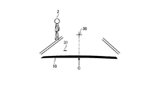
図10は、車両1の上方から見たときの虚像31の表示範囲の一例を示す図である。光源パネル10をインストルメントパネル22に前記で例示したように搭載した車両1が、例えば歩道幅1(m)・車線幅3.2(m)の道路に在る場合、アイポイント30から見た虚像31の表示範囲(危険対象の範囲)は、左側8.1(m)・右側22.5(m)までの図示の範囲となる。
FIG. 10 is a diagram illustrating an example of a display range of the
図1に戻り、点灯制御部15は、対物センサ11で検出した車両1周辺の車外環境、ドライバセンサ12で検出した運転者の注視点または注視方向、車速センサ13で検出した車両1の車速、およびリスク演算部14aで演算した車両1周辺の危険の度合い等に基づいて、常時用、注意喚起用または警告用の点灯パターン(例えば、フロントウインドウガラス20における光の照射位置、フロントウインドウガラス20における光の照射面積、光の色、光の輝度、光の周期(点滅)、光の色または輝度の単位変化当りの変化量(色または輝度の単位変化量)などに関する点灯内容または点灯態様)を生成し、生成した点灯パターンとなるように個々の光源10aの点灯制御(例えば印加電圧の調整など)を実行する。
Returning to FIG. 1, the lighting control unit 15 detects the environment around the
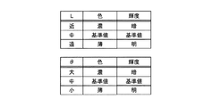
ここで、光源10aの光の色および輝度の調整(キャリブレーション)手法の一例を、図11から図13を参照して説明する。図11に示すように、個々の光源10aの色および輝度は、予め、距離Lおよび/または角度θに応じて調整する。例えば、個々の光源10aの色および輝度は、距離Lと色・輝度との関係を定義したマップ(図12参照)および/または角度θと色・輝度との関係を定義したマップ(図12参照)に基づいて調整する。ここで、距離Lは、光源10aから、フロントウインドウガラス20における当該光源10aの光の照射位置までの距離である。角度θは、光源10aの配置位置と光の照射位置とを結んだ線分とフロントウインドウガラス20とのなす角度である。また、常時、注意喚起時および警告時における個々の光源10aの色および輝度は、予め、例えばインストルメントパネル、Aピラー、またはサイドミラーなどの色に応じて調整する。例えば、常時、注意喚起時および警告時における個々の光源10aの色および輝度は、車体色と常時色・注記喚起色・警告色・輝度との関係を定義したマップ(図13参照)に基づいて調整する。これらの色・輝度に関する調整の状態は、点灯制御部15の記憶領域に記憶される。
Here, an example of a method for adjusting (calibrating) the color and brightness of light from the
なお、点灯制御部15は、光の輝度または色を、ヘッドライトのオン・オフまたはコンライトセンサなどで調整してもよい。例えば、点灯制御部15は、夜間の場合に光の輝度を下げてもよい。また、点灯制御部15は、リスク演算部14aで推定した危険の度合いの信頼性の大小に応じて、光の輝度・色・周期(点滅)などを調整してもよい。また、点灯制御部15は、ドライバセンサ12で検出した運転者の注視点または注視方向に基づいて、点灯している光のうち運転者が認識した光を停止してもよく、またこの光の輝度・色などを低減してもよい。また、点灯制御部15は、危険対象の存在位置または存在方向に合わせて、危険対象の内容(例えば、危険対象が人であるとか車であるとか等)も告知してもよい。 Note that the lighting control unit 15 may adjust the luminance or color of the light by turning on / off the headlight, a conlight sensor, or the like. For example, the lighting control unit 15 may reduce the luminance of light at night. Further, the lighting control unit 15 may adjust the luminance, color, period (flashing), and the like of light according to the reliability of the degree of danger estimated by the risk calculation unit 14a. Further, the lighting control unit 15 may stop the light recognized by the driver among the lights that are lit based on the driver's gazing point or the gazing direction detected by the driver sensor 12. Luminance, color, etc. may be reduced. The lighting control unit 15 may also notify the contents of the dangerous object (for example, whether the dangerous object is a person or a car) according to the position or direction of the dangerous object.
図1に戻り、透過制御部16は、対物センサ11で検出した車両1周辺の車外環境、ドライバセンサ12で検出した運転者の注視点または注視方向、車速センサ13で検出した車両1の車速、リスク演算部14で演算した車両1周辺の危険の度合い、および点灯制御部15で生成した点灯パターンなどに基づいて、光源パネル10における光源10aの光の透り具合(ぼけ具合/拡散性)を調整する。
Returning to FIG. 1, the transmission control unit 16 detects the environment outside the
例えば、点灯制御部15が注意喚起用の点灯パターンで光源10aを点灯させる場合、透過制御部16は、図2に示す光源パネル10が用いられる場合は光源10aと拡散板10bとの距離を全体的に長くし、図3に示す光源パネル10が用いられる場合は拡散板10bと導光部材10eと距離を全体的に長くし、そして図4に示す光源パネル10が用いられる場合は液晶パネル10fの開口率を全体的に小さくする。これにより、虚像31を、図14に示すようなくっきりとした状態から、図15に示すようなぼんやりとした、ぼけた状態に変えることができる。つまり、虚像31をぼかすことができる。
For example, when the lighting control unit 15 turns on the
また、透過制御部16は、リクス演算部14aで演算した危険の度合いに応じて、図2に示す光源パネル10が用いられる場合は光源10aと拡散板10bとの距離を、図3に示す光源パネル10が用いられる場合は拡散板10bと導光部材10eとの距離を、そして図4に示す光源パネル10が用いられる場合は液晶パネル10fの開口率を調整する。透過制御部16は、危険の度合いが小さいときは、光源10aと拡散板10bとの距離を全体的に長くし、拡散板10bと導光部材10eとの距離を全体的に長くし、そして開口率を全体的に小さくする。また、透過制御部16は、危険の度合いが大きいときは、光源10aと拡散板10bとの距離を全体的に短くし、拡散板10bと導光部材10eとの距離を全体的に短くし、そして開口率を全体的に大きくする。これにより、リクスが高いときには虚像31をくっきりとした状態で映し出すことができ、リクスが低いときは虚像31をぼんやりとした、ぼけた状態で映し出すことができる。
Further, the transmission control unit 16 determines the distance between the
また、点灯制御部15が特定の情報(例えば文字およびアイコンなど)を表示する点灯パターンで光源10aを点灯させる場合、透過制御部16は、図2に示す光源パネル10が用いられる場合は光源10aと拡散板10bとの距離を全体的に短くし、図3に示す光源パネル10が用いられる場合は拡散板10bと導光部材10eとの距離を全体的に短くし、そして図4に示す光源パネル10が用いられる場合は液晶パネル10fの開口率を全体的に大きくする。これにより、特定の情報に対応する虚像31をくっきりした状態で映し出すことができる。
Further, when the lighting control unit 15 lights the
また、透過制御部16は、車速センサ13で検出した車両1の車速に応じて、図2に示す光源パネル10が用いられる場合は光源10aと拡散板10bとの距離を、図3に示す光源パネル10が用いられる場合は拡散板10bと導光部材10eとの距離を、そして図4に示す光源パネル10が用いられる場合は液晶パネル10fの開口率を調整する。透過制御部16は、車速が所定値以下のとき(例えば車両1が停止中のとき等)は、光源10aと拡散板10bとの距離を全体的に短くし、拡散板10bと導光部材10eとの距離を全体的に短くし、そして開口率を全体的に大きくする。一方で、透過制御部16は、車速が所定値を超えたとき(例えば車両1が走行中のとき等)は、光源10aと拡散板10bとの距離を全体的に長くし、拡散板10bと導光部材10eとの距離を全体的に長くし、そして開口率を全体的に小さくする。これにより、車両1が停止中のときは、図16に示すように虚像31をくっきりとした状態で映し出すことができ、車両1が走行中のときは、図17に示すように虚像31をぼんやりとした、ぼけた状態で映し出すことができる。
Further, the transmission control unit 16 determines the distance between the
また、図2に示す光源パネル10が用いられる場合、透過制御部16は、拡散板10bにおける、ドライバセンサ12で検出した運転者の注視点38近傍に光を照射する光源10aの配置位置と対応する部分だけ、光源10aとの距離を部分的に長くする。図3に示す光源パネル10が用いられる場合、透過制御部16は、注視点38近傍に光を照射する光源10aに配置された導光部材10eだけ、拡散板10bとの距離を部分的に長くする。図4に示す光源パネル10が用いられる場合、透過制御部16は、液晶パネル10fにおける、注視点38近傍に光を照射する光源10aの配置位置と対応する部分だけ、開口率を小さくする。これにより、図18に示すように、虚像31のうち運転者が見た部分(注視点38近傍の部分)だけを、選択的にぼんやりとした、ぼけた状態で映し出すことができる。
When the
また、透過制御部16は、左カーブ・右カーブなどといった道路形状に応じて、光源パネル10における光源10aの光の透り具合を調整する。図2に示す光源パネル10が用いられる場合、透過制御部16は、拡散板10bにおける、運転者が注視する道路形状の変化方向(例えば右カーブなら右方向、左カーブなら左方向)に光を照射する光源10aの配置位置と対応する部分だけ、光源10aとの距離を部分的に長くする。図3に示す光源パネル10が用いられる場合、透過制御部16は、道路形状の変化方向に光を照射する光源10aに配置された導光部材10eだけ、拡散板10bとの距離を部分的に長くする。図4に示す光源パネル10が用いられる場合、透過制御部16は、液晶パネル10fにおける、道路形状の変化方向に光を照射する光源10aの配置位置と対応する部分だけ、開口率を小さくする。これにより、図19に示すように、虚像31のうち運転者が注視するカーブ方向の部分(注視方向34近傍の部分)だけを選択的にぼんやりとした、ぼけた状態で映し出すことができる。
Further, the transmission control unit 16 adjusts the light transparency of the
また、透過制御部16は、運転者の中心視野(ドライバセンサ12で検出した運転者の注視点38)から虚像31までの距離に応じて、光源パネル10における光源10aの光の透り具合を調整する。図2に示す光源パネル10が用いられる場合、透過制御部16は、注視点38との距離が相対的に短い光源10aと拡散板10bとの距離を相対的に長くし、注視点38との距離が相対的に長い光源10aと拡散板10bとの距離を相対的に短くし、注視点38との距離が相対的に中間程度の距離となる光源10aと拡散板10bとの距離を相対的に中間程度の距離にする。図3に示す光源パネル10が用いられる場合、透過制御部16は、注視点38との距離が相対的に短い光源10aに配置された導光部材10eと拡散板10bとの距離を相対的に長くし、注視点38との距離が相対的に長い光源10aに配置された導光部材10eと拡散板10bとの距離を相対的に短くし、注視点38との距離が相対的に中間程度の距離となる光源10aに配置された導光部材10eと拡散板10bとの距離を相対的に中間程度の距離にする。図4に示す光源パネル10が用いられる場合、透過制御部16は、注視点38との距離が相対的に短い光源10aの配置位置と対応する液晶パネル10fの部分の開口率を相対的に小さく、注視点38との距離が相対的に長い光源10aの配置位置と対応する液晶パネル10fの部分の開口率を相対的に大きくし、注視点38との距離が相対的に中間程度の距離となる光源10aの配置位置と対応する液晶パネル10fの部分の開口率を相対的に中間程度の大きさにする。これにより、図20に示すように、虚像31を、注視点38との距離が短い位置から長い位置に向って、はぼんやりとした、ぼけた状態から、徐々に、くっきりとした状態に変えることができる。
In addition, the transmission control unit 16 determines the light transparency of the
〔2.動作〕
図21は、本実施形態にかかる車両用情報伝達システムで実行されるリスク演算動作および点灯制御動作の一例を示すフローチャートである。
[2. Operation)
FIG. 21 is a flowchart illustrating an example of a risk calculation operation and a lighting control operation executed in the vehicle information transmission system according to the present embodiment.
〔ステップSA1:車外環境の計測〕
対物センサ11は、車両1周辺の対象(例えば歩行者・自転車・自動車・死角など)に関する情報を計測する。
[Step SA1: Measurement of the environment outside the vehicle]
The
〔ステップSA2:車外環境の認識〕
リスク演算部14aは、ステップSA1で計測した対象に関する情報に基づいて、車両1周辺の状態が、対象が存在しない注意喚起または警告の必要がない通常の状態であるか、それとも対象が存在する注意喚起または警告の必要がある状態であるかを認識する。例えば、リスク演算部14aは、対象が存在しない場合には通常の状態と認識し、対象が存在する場合には注意喚起または警告の必要がある状態と認識する。
[Step SA2: Recognition of the environment outside the vehicle]
Based on the information about the object measured in step SA1, the risk calculator 14a determines whether the state around the
〔ステップSA3:危険度合いの演算〕
ステップSA2において車両1周辺の状態が注意喚起または警告の必要がある状態と認識された場合には、リスク演算部14aは、ステップSA1で計測した対象に関する情報に基づいて、対象の存在位置を確認する。リスク演算部14aは、存在位置が確認できなかった対象については、危険の度合いが小さい(注意喚起の必要がある状態)と推定する。
[Step SA3: Risk level calculation]
When it is recognized in step SA2 that the state around the
リスク演算部14aは、存在位置が確認できた対象については、対象と車両1との距離および車両1に対する対象の相対減速度(相対速度または相対加速度でもよい。)を計算する。リスク演算部14aは、この距離が短ければ危険の度合いが大きい(警告の必要がある状態)と推定し、長ければ小さい(注意喚起の必要がある状態)と推定する。また、リクス演算部14aは、車両1に対する対象の相対減速度が小さければ危険の度合いが小さい(注意喚起の必要がある状態)と推定し、大きければ大きい(警告の必要がある状態)と推定する。
The risk calculating unit 14a calculates the distance between the object and the
〔ステップSA4:光刺激パターンの生成〕
点灯制御部15は、ステップSA3で確認できた対象の存在位置およびステップSA3で推定した対象の危険の度合いに基づいて、対象の位置および危険の度合いと光の照射位置および照射面積との関係を定義した図22に示すマップを参照して、告知用の光の照射位置(横方向および縦(高さ)方向の照射位置)および照射面積を決定すると共に、必要に応じて、注意配分用の光の照射位置および照射面積も決定する。例えば、告知用の光の照射位置は、対象の存在位置が左側であれば左側に、正面であれば正面に、右側であれば右側に設定される。一方、注意配分用の光の照射位置は、告知用の光の照射位置が左側であれば右側に、右側であれば左側に設定され、正面または左右両方であれば設定されない。また、告知用の光の照射面積は、対象の危険の度合いが大きい警告時のときは大きく設定され、対象の危険の度合いが小さい注意喚起時のときは小さく設定される。一方、注意配分用の光の照射面積は、対象の危険の度合いが大きい警告時のときは、告知用の光の照射面積との違いが明確になる程度に小さく設定され、対象の危険の度合いが小さい注意喚起時のときは、告知用の光の照射面積との違いがそれほどない程度に多少小さく設定される。
[Step SA4: Generation of Light Stimulation Pattern]
The lighting control unit 15 determines the relationship between the target position and the degree of danger, the irradiation position of the light, and the irradiation area based on the position of the target that can be confirmed in Step SA3 and the degree of the target danger estimated in Step SA3. With reference to the map shown in FIG. 22, the irradiation position of the light for notification (irradiation position in the horizontal direction and vertical (height) direction) and the irradiation area are determined and, if necessary, for attention distribution. The irradiation position and irradiation area of light are also determined. For example, the irradiation position of the light for notification is set to the left side when the target position is the left side, to the front side when it is the front side, and to the right side when it is the right side. On the other hand, the irradiation position of the attention distribution light is set to the right side if the irradiation position of the notification light is on the left side, the left side if it is the right side, and is not set if it is both front or left and right. Further, the irradiation area of the light for notification is set to be large at the time of warning when the degree of danger of the target is large, and is set to be small at the time of alerting when the degree of danger of the target is small. On the other hand, the light distribution area for attention distribution is set so small that the difference from the light irradiation area for notification is clear when the warning level is high. Is set to be slightly small so that there is not much difference from the irradiation area of the light for notification.
点灯制御部15は、ステップSA3で推定した対象の危険の度合いならびに図12および図13に示すマップに従って予め調整されて記憶した色・輝度の状態に基づいて、告知用の光の色・輝度を決定すると共に、必要に応じて、告知用の光の色・輝度とは異なる、注意配分用の光の色・輝度も決定する。また、点灯制御部15は、ステップSA3で推定した対象の危険の度合いに基づいて、告知用の光の色・輝度の単位変化当りの変化量(単位変化量)を決定する。例えば、図23に示すように、危険の度合いの単位時間当たりの変化が大きいときは、色・輝度の単位変化量は大きく設定され、危険の度合いの単位時間当たりの変化が小さいときは、色および輝度の単位変化量は小さく設定される。 The lighting control unit 15 determines the color / brightness of the notification light based on the degree of danger of the target estimated in step SA3 and the color / brightness state adjusted and stored in advance according to the maps shown in FIGS. At the same time, if necessary, the color / brightness of the light for attention distribution, which is different from the color / brightness of the light for notification, is also determined. Further, the lighting control unit 15 determines a change amount (unit change amount) per unit change in the color and luminance of the notification light based on the degree of danger of the target estimated in step SA3. For example, as shown in FIG. 23, when the change in the degree of danger per unit time is large, the unit change amount of the color / brightness is set large, and when the change in the degree of danger per unit time is small, the color The unit change amount of luminance is set small.
点灯制御部15は、前記で決定した光の照射位置・照射面積・色・輝度・単位変化量を含む告知用(注意喚起用または警告用)の点灯パターンを生成する。ここで、ステップSA2で車両1周辺の状態が注意喚起の必要がない通常の状態と認識された場合には、点灯制御部15は、図12および図13に示すマップに従って予め調整されて記憶した色・輝度の状態に基づいて、常時用の光の色・輝度を含む、告知用の点灯パターンとは異なる常時用の点灯パターンを生成する。
The lighting control unit 15 generates a lighting pattern for notification (for alerting or warning) including the light irradiation position, irradiation area, color, luminance, and unit change amount determined above. Here, when it is recognized in step SA2 that the state around the
〔ステップSA5:光刺激表示〕
点灯制御部15は、道路形状に応じて光源パネル10における点灯時の中心位置を設定(補正)し、ステップSA4で生成した告知用または常時用の点灯パターンおよび当該設定した中心位置に基づいて、当該点灯パターンとなるように個々の光源10aの点灯制御を実行する。
[Step SA5: Light stimulus display]
The lighting control unit 15 sets (corrects) the center position at the time of lighting in the
以上、上述したリスク演算動作および点灯制御動作によれば、警告が必要な図24に示すような状況(例えば危険の度合いが大きい対象2が運転者から見て左に存在する状況)では、対象2の危険の度合いに応じて設定した告知用の虚像31を左方向に映し出すと共に、さらに車両1周辺への運転者の注意配分の総和が一定となるように設定した注意配分用のダミーの虚像31を、当該総和が一定となるように設定した右方向にも映し出すので、当該状況において、車両1周辺への運転者の注意を均一に保つ(均す)ことができる。
As described above, according to the risk calculation operation and the lighting control operation described above, in the situation as shown in FIG. The
また、上述したリスク演算動作および点灯制御動作によれば、注意喚起または警告が必要ない図25に示すような通常(安全)の状況(例えば車両1周辺に対象が存在しない状況)では、告知用とは異なる、色調が下げられた弱めの常時用の虚像31を、例えば運転者から見て左方向・中央(正面)方向、右方向または全体に映し出す。また、通常の状況から対象2が出現して警告が必要な状況に変わった図26に示すような場合には、最下層に在る常時点灯用の緑色の虚像31のうち当該対象2の存在位置または存在方向と対応する部分(図26では最下層・左側の部分)の点灯状態を弱め、一方で、最上層に在る警告用の赤色の虚像31のうち当該部分(図26では最上層・左側の部分)の点灯状態を強める。これらにより、通常の状況から注意喚起または警告が必要な状況に変わったときに、運転者に注意喚起または警告を、より違和感なく・唐突さなく・自然に促すことができる。
Further, according to the risk calculation operation and the lighting control operation described above, in a normal (safe) situation (for example, a situation where there is no target around the vehicle 1) as shown in FIG. A weak
また、上述したリスク演算動作および点灯制御動作によれば、告知が必要な状況において車両1が直線の道路を走行している図27に示すような場合には、点灯時の中心位置Cを道路形状に合わせて運転者から見て中央(正面)に設定(補正)し、また、車両1が右カーブの道路を走行している図28に示すような場合には、点灯時の中心位置Cを道路形状に合わせて運転者から見て右に設定(補正)し、そして、当該中心位置Cの設定に基づいて告知用の虚像31を映し出す。これにより、運転者の視界から外れない範囲(運転者の注視方向から一定の範囲)で運転者に注意喚起または警告を促すことができる。
Further, according to the risk calculation operation and the lighting control operation described above, when the
また、上述したリスク演算動作および点灯制御動作によれば、先行車両である対象2の相対減速度Vが小さい注意喚起が必要な図29に示すような状況では、単位変化量が小さく設定された注意喚起用の虚像31を映し出し、また、対象2の相対減速度Vが大きい警告が必要な図30に示すような状況では、単位変化量が大きく設定された警告用の虚像31を映し出すので、車両1と対象との相対関係に合った点灯内容で運転者に注意喚起または警告を促すことができる。
Further, according to the risk calculation operation and the lighting control operation described above, the unit change amount is set to be small in the situation shown in FIG. 29 in which the relative deceleration V of the
〔3.本実施形態のまとめ〕
以上、本実施形態によれば、インストルメントパネル22の所定の位置に搭載された光源パネル10にアレイ状(複数行または複数列)に配置された複数の光源10aの光を、危険対象(例えば、歩行者、自転車、自動車、および死角など)の存在位置または存在方向に対応するフロントウインドウガラス20の部分に、危険対象の危険の度合い等に応じた色・輝度・面積・周期等で照射することで、運転者に注意喚起または警告を促す。ここで、例えば従来のナイトビューシステムでは、夜間に赤外線センサで人物を検知すると、検知した人物を枠で囲んで画面で知らせているが、画面に表示された内容と実際の状況との対応関係が運転者にとって分かり難かった。しかし、本実施形態によれば、危険対象の位置または方向を運転者に分かり易く確実に気付かせる(告知する)ことと、運転者に対して煩わしさ・違和感が無いように告知することを両立することができる。
[3. Summary of this embodiment]
As described above, according to the present embodiment, the light of the plurality of
また、本実施形態によれば、各々の光源10aの光の輝度(印加電圧)および色を、光源10aの配置位置からフロントウインドウガラス20における光源10aからの光の照射位置までの距離、および/または当該配置位置および当該照射位置を結んだ線分とフロントウインドウガラス20とのなす角度に応じて設定する。例えば、光の輝度は、当該照射位置との距離が長い光源10aほど大きく設定する。これにより、運転者にとって車体に反射した光がより視認し易くなり、その結果、情報の伝達効率を向上させることができる。また、運転者のアイポイントに合わせて、光を見易い位置に合わせることができる。
Further, according to the present embodiment, the light intensity (applied voltage) and color of each
また、本実施形態によれば、光源パネル10には、光源10aの光の輝度(光の透り具合またはぼけ具合(ぼけ度合い))を調整する機構が備えられている。これにより、光が強いことに因る煩わしさを解消することができる。例えば、或る位置または方向の確認を運転者に促す場合には光の輝度を下げて虚像をぼかし、文字・アイコン等の特定の情報を伝達する場合には光の輝度を上げて虚像をくっきりと映す。これにより、運転者は、虚像に焦点が合い難くなり、前景がより見やすくなる。また、特定の情報を伝達する場合において、車両1が所定速度を超える速度で走行しているときには光の輝度を下げて虚像をぼかす。これにより、停車中には中心視に因る視認行動を誘導して詳細な情報を提示することができ、走行中には周辺視による視認行動を誘導して危険の存在と位置のみを伝達することができる。つまり、停車中は伝達する情報の量・質を向上させることができ、走行中は伝達する情報の量・質を抑制することができる。また、運転者が認識した光の照射位置に対応する光源10aだけ選択的に光の輝度を下げて虚像を部分的にぼかす。これにより、運転者は、一度見た虚像に焦点が合い難くなり、直接視に因る視点停留時間を低減することができる。また、車両1周辺の危険の度合いが高い等、伝達する情報の質・優先度が高いほど、光の輝度を上げて虚像をくっきりと映す。これにより、重要な情報を運転者に確実に伝達することができる。また、道路形状(カーブ)から運転者が最も重視すべき視線方向を推定し、この方向へ照射する光の輝度を下げて虚像をぼかす。これにより、カーブ走行中において、注視方向の虚像に焦点が合い難くなり、前景がより見やすくなる。また、中心視からの遠さ・近さに応じて、光の輝度を調整して虚像のぼけ度合いを変更する。これにより、中心視に近い方がより明確な形状を捉えやすいという人間特性を考慮して、伝達する情報の量・質を適正化することができる。
Further, according to the present embodiment, the
また、本実施形態によれば、対象の存在位置または存在方向を告知する場合には、当該対象の危険の度合い等に応じた告知用の虚像を当該存在位置または存在方向に映し出すと共に、当該存在位置または存在方向とは異なる位置または方向にも当該告知用の虚像とは異なる注意配分用の虚像を映し出す。例えば、危険対象が左または右にある場合、危険の度合いに応じて点灯内容の配分を合わせる(変える)。これにより、対象の確認を運転者に適確に促しつつ、車両1周辺への運転者の注意配分を通常時と同程度に維持することができる。また、複数同時点灯時に各危険の内容に合わせて、点灯状態を各々変えることができる。また、一体的ではなく、非連続に分離した位置のそれぞれに対して、運転者に認識を促す。これにより、広い範囲の認識を促しつつも、認識すべき箇所に好適に注意配分を行うことができる。なお、緊急性の高い情報を告知する際は、当該情報に対応する告知用の虚像を、注意配分用の虚像よりも時間的に早く映し出してもよい。
Further, according to the present embodiment, when notifying the presence position or direction of the target, a virtual image for notification corresponding to the degree of danger of the target is displayed in the presence position or direction and the presence A virtual image for attention distribution that is different from the virtual image for notification is also displayed at a position or direction different from the position or direction of presence. For example, when the danger target is on the left or right, the distribution of lighting contents is adjusted (changed) according to the degree of danger. Accordingly, the driver's attention distribution to the periphery of the
また、本実施形態によれば、通常の状態でも、車両前方の左側、中央または右側の光源10aを常時用の点灯内容で常時点灯する。これにより、通常の状態から告知する状態になったときに、光を目立たせ過ぎずに、運転者に違和感なく注意喚起または警告を促すことができる。
Further, according to the present embodiment, even in a normal state, the
また、本実施形態によれば、車両1周辺の危険の度合いの変化に応じて、光の色・輝度の変化の段階的な荒さを変える。例えば、車両1周辺の危険の度合いの変化が大きいときは単位変化当りの輝度および/または色の変化量が大きい、つまり変化の荒い光を照射し、小さいときは単位変化当りの輝度および/または色の変化量が小さい、つまり変化の細かい光を照射する。つまり、危険との相対関係に応じて光の輝度および/または色の変化量を変える。これにより、危なさの感じ方を変えて、運転者に危険の度合いの変化を明確に伝達することができる。また、伝達する情報の優先度に応じて、光の色・輝度の変化の段階的な荒さを変える。例えば、優先度の高い情報を伝達するときは単位変化当りの輝度および/または色の変化量が大きい、つまり変化の荒い光を照射し、優先度の低い情報を伝達するときは単位変化当りの輝度および/または色の変化量が小さい、つまり変化の細かい光を照射する。これにより、運転者に情報の重要性を明確に伝達することができる。
Further, according to the present embodiment, the stepwise roughness of the change in the color and brightness of the light is changed according to the change in the degree of danger around the
以上のように、本発明にかかる車両用情報伝達装置は、自動車製造産業において有用であり、特に、車体を利用した運転者への情報伝達に適している。 As described above, the vehicle information transmission device according to the present invention is useful in the automobile manufacturing industry, and is particularly suitable for information transmission to a driver using a vehicle body.
10 光源パネル
10a 光源
10b 拡散板
10c 軸部材
10d バネ
11 対物センサ
12 ドライバセンサ
13 車速センサ
14 ECU
14a リスク演算部
15 点灯制御部
16 透過制御部
20 フロントウインドウガラス
22 インストルメントパネル
31 虚像
DESCRIPTION OF
14a Risk calculation unit 15 Lighting control unit 16
Claims (4)
前記或る対象の位置とは異なる位置の認識を促し、
前記或る対象の位置が運転者から見て左側の場合には、前記異なる位置は前記運転者から見て右側であり、前記或る対象の位置が前記運転者から見て右側の場合には、前記異なる位置は前記運転者から見て左側であり、
前記或る対象の認識を促している最中に、前記異なる位置の認識を促すこと、
を特徴とする車両用情報伝達装置。 A vehicle information transmission device that promotes recognition of an object,
Promotes recognition of a position different from the position of the object;
When the position of the certain object is on the left side when viewed from the driver, the different position is on the right side when viewed from the driver, and when the position of the certain object is on the right side when viewed from the driver It said different positions Ri left der viewed from the driver,
Prompting the recognition of the different location while prompting the recognition of the certain object ;
A vehicle information transmission device characterized by the above.
前記或る対象の位置と前記異なる位置とは、互いに離間した位置であること、
を特徴とする車両用情報伝達装置。 The vehicle information transmission device according to claim 1,
The position of the certain object and the different position are positions separated from each other;
A vehicle information transmission device characterized by the above.
前記或る対象の認識の促し方と前記異なる位置の認識の促し方とは異なること、
を特徴とする車両用情報伝達装置。 The vehicle information transmission device according to claim 1,
The method of promoting recognition of the certain object is different from the method of promoting recognition of the different position;
A vehicle information transmission device characterized by the above.
或る対象の確認を前記右側または前記左側で促す場合には、前記第一の表示部および前記第二の表示部のそれぞれで、前記右側および前記左側の確認を促し、
前記或る対象の確認を前記右側で促している最中に前記左側の確認を促し、前記或る対象の確認を前記左側で促している最中に前記右側の確認を促すこと、
を特徴とする車両用情報伝達装置。 A first display unit that prompts confirmation on the right side when viewed from the driver and a second display unit that prompts confirmation on the left side when viewed from the driver;
When the prompt confirmation of certain target at the right or the left, in each of the first display unit and the second display unit, and prompting a confirmation of the right and the left,
Said prompting the confirmation of the left-hand side in the middle of the confirmation of a certain object is prompted by the right side, the right side of the check the prompting Succoth the confirmation of a certain object in the middle of prompting by the left-hand side,
A vehicle information transmission device characterized by the above.
Priority Applications (8)
| Application Number | Priority Date | Filing Date | Title |
|---|---|---|---|
| JP2010273883A JP5582008B2 (en) | 2010-12-08 | 2010-12-08 | Vehicle information transmission device |
| CN201180058856.9A CN103249588B (en) | 2010-12-08 | 2011-12-05 | Information of vehicles sending set |
| KR1020137014534A KR101437803B1 (en) | 2010-12-08 | 2011-12-05 | Vehicle information transmission device |
| US13/990,886 US8937536B2 (en) | 2010-12-08 | 2011-12-05 | Vehicle information transmission device |
| PCT/IB2011/002923 WO2012076954A2 (en) | 2010-12-08 | 2011-12-05 | Vehicle information transmission device |
| BR112013014011A BR112013014011A2 (en) | 2010-12-08 | 2011-12-05 | vehicle information transmission device |
| RU2013126424/11A RU2531790C1 (en) | 2010-12-08 | 2011-12-05 | Vehicle data transfer device |
| ZA2013/04273A ZA201304273B (en) | 2010-12-08 | 2013-06-11 | Vehicle information transmission device |
Applications Claiming Priority (1)
| Application Number | Priority Date | Filing Date | Title |
|---|---|---|---|
| JP2010273883A JP5582008B2 (en) | 2010-12-08 | 2010-12-08 | Vehicle information transmission device |
Publications (3)
| Publication Number | Publication Date |
|---|---|
| JP2012123629A JP2012123629A (en) | 2012-06-28 |
| JP2012123629A5 JP2012123629A5 (en) | 2013-06-06 |
| JP5582008B2 true JP5582008B2 (en) | 2014-09-03 |
Family
ID=45558773
Family Applications (1)
| Application Number | Title | Priority Date | Filing Date |
|---|---|---|---|
| JP2010273883A Active JP5582008B2 (en) | 2010-12-08 | 2010-12-08 | Vehicle information transmission device |
Country Status (8)
| Country | Link |
|---|---|
| US (1) | US8937536B2 (en) |
| JP (1) | JP5582008B2 (en) |
| KR (1) | KR101437803B1 (en) |
| CN (1) | CN103249588B (en) |
| BR (1) | BR112013014011A2 (en) |
| RU (1) | RU2531790C1 (en) |
| WO (1) | WO2012076954A2 (en) |
| ZA (1) | ZA201304273B (en) |
Families Citing this family (26)
| Publication number | Priority date | Publication date | Assignee | Title |
|---|---|---|---|---|
| WO2012077202A1 (en) * | 2010-12-08 | 2012-06-14 | トヨタ自動車株式会社 | Information conveyance device for use in vehicle |
| JP5821179B2 (en) | 2010-12-08 | 2015-11-24 | トヨタ自動車株式会社 | Vehicle information transmission device |
| JP5272042B2 (en) * | 2011-05-12 | 2013-08-28 | 富士重工業株式会社 | Environment recognition apparatus and environment recognition method |
| FR2977840B1 (en) * | 2011-07-12 | 2014-02-21 | Faurecia Interieur Ind | INFORMATION DISPLAY SYSTEM IN A VEHICLE |
| US9085262B2 (en) | 2012-10-08 | 2015-07-21 | Microsoft Technology Licensing, Llc | Tinting indication of environmental conditions |
| JP5983547B2 (en) | 2013-07-02 | 2016-08-31 | 株式会社デンソー | Head-up display and program |
| JP5842110B2 (en) * | 2013-10-10 | 2016-01-13 | パナソニックIpマネジメント株式会社 | Display control device, display control program, and recording medium |
| JP6364627B2 (en) * | 2013-11-01 | 2018-08-01 | パナソニックIpマネジメント株式会社 | Gaze direction detection device and gaze direction detection method |
| US20150235538A1 (en) * | 2014-02-14 | 2015-08-20 | GM Global Technology Operations LLC | Methods and systems for processing attention data from a vehicle |
| US9262924B2 (en) * | 2014-07-09 | 2016-02-16 | Toyota Motor Engineering & Manufacturing North America, Inc. | Adapting a warning output based on a driver's view |
| JP6327034B2 (en) * | 2014-07-22 | 2018-05-23 | 株式会社デンソー | Display control device for vehicle |
| JP6746270B2 (en) | 2014-09-08 | 2020-08-26 | 株式会社小糸製作所 | Vehicle display system |
| US20160193961A1 (en) * | 2015-01-05 | 2016-07-07 | Myine Electronics, Inc. | Methods and systems for visual communication of vehicle drive information using a light set |
| US10099608B2 (en) * | 2015-01-16 | 2018-10-16 | Ford Global Technologies, Llc | Haptic vehicle alert based on wearable device |
| JP6319349B2 (en) * | 2015-04-03 | 2018-05-09 | 株式会社デンソー | Information presentation device |
| FR3056499B1 (en) * | 2016-09-28 | 2021-04-30 | Valeo Vision | AIR QUALITY INDICATOR OF A MOTOR VEHICLE INTERIOR |
| US10109200B1 (en) * | 2017-06-29 | 2018-10-23 | GM Global Technology Operations LLC | Graphical multi-layer light alert display and control method thereof |
| WO2019031291A1 (en) | 2017-08-10 | 2019-02-14 | 日本精機株式会社 | Vehicle display device |
| WO2019070080A1 (en) * | 2017-10-05 | 2019-04-11 | コニカミノルタ株式会社 | Display device |
| JP2019086805A (en) * | 2017-11-01 | 2019-06-06 | トヨタ自動車株式会社 | In-vehicle system |
| US10876856B2 (en) * | 2018-01-10 | 2020-12-29 | Gulfstream Aerospace Corporation | Aircraft HUD with curved tapes and flight mode annunciation boxes |
| US11590985B2 (en) * | 2018-08-09 | 2023-02-28 | Sony Semiconductor Solutions Corporation | Information processing device, moving body, information processing method, and program |
| KR20220016275A (en) * | 2019-07-12 | 2022-02-08 | 닛산 지도우샤 가부시키가이샤 | Information processing device, information processing method, and program |
| EP3782840B1 (en) * | 2019-08-20 | 2023-08-02 | Volvo Car Corporation | Aid for a driver with impaired field of view |
| KR20210053385A (en) * | 2019-11-01 | 2021-05-12 | 엘지전자 주식회사 | Vehicle Having a Dangerous Situation Notification Function and Control Method thereof |
| JP6990274B1 (en) * | 2020-06-29 | 2022-01-12 | 本田技研工業株式会社 | How to control the alert device, mobile object, and alert device |
Family Cites Families (20)
| Publication number | Priority date | Publication date | Assignee | Title |
|---|---|---|---|---|
| JP3626229B2 (en) | 1994-10-13 | 2005-03-02 | 本田技研工業株式会社 | Vehicle driving support system |
| JP4075026B2 (en) * | 1998-12-03 | 2008-04-16 | マツダ株式会社 | Vehicle obstacle warning device |
| JP2002274216A (en) | 2001-03-14 | 2002-09-25 | Nissan Motor Co Ltd | Indicator for vehicle |
| JP2003054334A (en) | 2001-08-13 | 2003-02-26 | Nissan Motor Co Ltd | Display for vehicle |
| JP4501778B2 (en) * | 2005-05-24 | 2010-07-14 | 日産自動車株式会社 | Vehicle information display method and vehicle information display device |
| CN1967147B (en) * | 2005-11-09 | 2011-08-17 | 日产自动车株式会社 | Vehicular driving assist operation device and vehicle possessing same |
| JP4887980B2 (en) * | 2005-11-09 | 2012-02-29 | 日産自動車株式会社 | VEHICLE DRIVE OPERATION ASSISTANCE DEVICE AND VEHICLE WITH VEHICLE DRIVE OPERATION ASSISTANCE DEVICE |
| CN200992171Y (en) * | 2006-12-12 | 2007-12-19 | 侯企东 | Right-left monitoring device of automobile |
| JP4843517B2 (en) | 2007-02-06 | 2011-12-21 | 本田技研工業株式会社 | Visual assist device for vehicles |
| JP2009113770A (en) * | 2007-11-09 | 2009-05-28 | Toyota Motor Corp | Vehicular display method and vehicular display device |
| JP2010120501A (en) | 2008-11-19 | 2010-06-03 | Yazaki Corp | Visual guide supporting device and vehicular display system |
| JP5392470B2 (en) * | 2009-01-30 | 2014-01-22 | マツダ株式会社 | Vehicle display device |
| US8629784B2 (en) * | 2009-04-02 | 2014-01-14 | GM Global Technology Operations LLC | Peripheral salient feature enhancement on full-windshield head-up display |
| JP2010254201A (en) * | 2009-04-28 | 2010-11-11 | Toyota Motor Corp | Visual sense stimulation device |
| JP4952765B2 (en) * | 2009-10-21 | 2012-06-13 | トヨタ自動車株式会社 | Vehicle night vision support device |
| WO2012077367A1 (en) | 2010-12-08 | 2012-06-14 | トヨタ自動車株式会社 | Information conveyance device for use in vehicle |
| JP5821179B2 (en) | 2010-12-08 | 2015-11-24 | トヨタ自動車株式会社 | Vehicle information transmission device |
| JP2012123628A (en) | 2010-12-08 | 2012-06-28 | Toyota Motor Corp | Information transmission device for vehicle |
| JP2012126251A (en) | 2010-12-15 | 2012-07-05 | Toyota Motor Corp | Light source device for vehicle |
| JP2012126252A (en) | 2010-12-15 | 2012-07-05 | Toyota Motor Corp | Light source device for vehicle |
-
2010
- 2010-12-08 JP JP2010273883A patent/JP5582008B2/en active Active
-
2011
- 2011-12-05 RU RU2013126424/11A patent/RU2531790C1/en active
- 2011-12-05 CN CN201180058856.9A patent/CN103249588B/en active Active
- 2011-12-05 KR KR1020137014534A patent/KR101437803B1/en active IP Right Grant
- 2011-12-05 US US13/990,886 patent/US8937536B2/en active Active
- 2011-12-05 WO PCT/IB2011/002923 patent/WO2012076954A2/en active Application Filing
- 2011-12-05 BR BR112013014011A patent/BR112013014011A2/en not_active IP Right Cessation
-
2013
- 2013-06-11 ZA ZA2013/04273A patent/ZA201304273B/en unknown
Also Published As
| Publication number | Publication date |
|---|---|
| US20130249684A1 (en) | 2013-09-26 |
| WO2012076954A3 (en) | 2012-08-23 |
| ZA201304273B (en) | 2014-08-27 |
| RU2531790C1 (en) | 2014-10-27 |
| JP2012123629A (en) | 2012-06-28 |
| WO2012076954A2 (en) | 2012-06-14 |
| US8937536B2 (en) | 2015-01-20 |
| CN103249588B (en) | 2016-02-10 |
| KR101437803B1 (en) | 2014-09-03 |
| CN103249588A (en) | 2013-08-14 |
| BR112013014011A2 (en) | 2016-09-13 |
| KR20130082167A (en) | 2013-07-18 |
| WO2012076954A8 (en) | 2013-12-19 |
Similar Documents
| Publication | Publication Date | Title |
|---|---|---|
| JP5582008B2 (en) | Vehicle information transmission device | |
| JP5821179B2 (en) | Vehicle information transmission device | |
| WO2012077202A1 (en) | Information conveyance device for use in vehicle | |
| JP5811100B2 (en) | Vehicle information transmission device | |
| JP5664784B2 (en) | Vehicle information transmission device | |
| US10787177B2 (en) | Exterior rearview device with illumination functions and autonomous vehicles using same | |
| JP2012126251A (en) | Light source device for vehicle | |
| JP2016199072A (en) | Vehicular display system | |
| JP5614366B2 (en) | Vehicle information transmission device | |
| JP2012123628A (en) | Information transmission device for vehicle | |
| JP2012126252A (en) | Light source device for vehicle | |
| JP5951976B2 (en) | Vehicle display device | |
| CN107891801B (en) | Control method of automobile auxiliary lighting system based on GPS navigation device | |
| JP2010280247A (en) | Display device for vehicle |
Legal Events
| Date | Code | Title | Description |
|---|---|---|---|
| A521 | Request for written amendment filed |
Free format text: JAPANESE INTERMEDIATE CODE: A523 Effective date: 20130418 |
|
| A621 | Written request for application examination |
Free format text: JAPANESE INTERMEDIATE CODE: A621 Effective date: 20130418 |
|
| A131 | Notification of reasons for refusal |
Free format text: JAPANESE INTERMEDIATE CODE: A131 Effective date: 20140212 |
|
| A521 | Request for written amendment filed |
Free format text: JAPANESE INTERMEDIATE CODE: A523 Effective date: 20140402 |
|
| TRDD | Decision of grant or rejection written | ||
| A01 | Written decision to grant a patent or to grant a registration (utility model) |
Free format text: JAPANESE INTERMEDIATE CODE: A01 Effective date: 20140617 |
|
| A61 | First payment of annual fees (during grant procedure) |
Free format text: JAPANESE INTERMEDIATE CODE: A61 Effective date: 20140630 |
|
| R151 | Written notification of patent or utility model registration |
Ref document number: 5582008 Country of ref document: JP Free format text: JAPANESE INTERMEDIATE CODE: R151 |