JP5581237B2 - Image processing device, processor device for electronic endoscope, operation method of image processing device, and computer program for image processing - Google Patents
Image processing device, processor device for electronic endoscope, operation method of image processing device, and computer program for image processing Download PDFInfo
- Publication number
- JP5581237B2 JP5581237B2 JP2011012122A JP2011012122A JP5581237B2 JP 5581237 B2 JP5581237 B2 JP 5581237B2 JP 2011012122 A JP2011012122 A JP 2011012122A JP 2011012122 A JP2011012122 A JP 2011012122A JP 5581237 B2 JP5581237 B2 JP 5581237B2
- Authority
- JP
- Japan
- Prior art keywords
- lesion
- signal
- evaluation
- image
- pixel
- Prior art date
- Legal status (The legal status is an assumption and is not a legal conclusion. Google has not performed a legal analysis and makes no representation as to the accuracy of the status listed.)
- Active
Links
Images

Landscapes
- Instruments For Viewing The Inside Of Hollow Bodies (AREA)
- Endoscopes (AREA)
- Closed-Circuit Television Systems (AREA)
- Color Television Image Signal Generators (AREA)
- Image Analysis (AREA)
Description
本発明は、内視鏡観察画像から病変部など異常と判断される部位を検出・表示するための画像処理装置に関する。 The present invention relates to an image processing apparatus for detecting and displaying a site determined to be abnormal such as a lesion from an endoscopic observation image.
内視鏡画像から病変部を自動的に検出する画像処理装置として、血液の吸収帯に相当するGチャンネル画像の対象画素に対して上下左右斜め方向にある周囲画素からの変化量を算出し、これに基づき病変部を検出するものが知られている(特許文献1)。 As an image processing device that automatically detects a lesion from an endoscopic image, the amount of change from surrounding pixels that are diagonally above, below, left, and right with respect to the target pixel of the G channel image corresponding to the blood absorption band is calculated, One that detects a lesion based on this is known (Patent Document 1).
しかし、上記特許文献1の方法では、表面粘膜の血管に変化のある病変は検出できるが、それ以外の病変部の特徴に基づいて危険部位を探知することはできない。例えば、病変部は表面粘膜における血管の変化の他に、血管新生、細胞の異常増殖による上皮層や腺管構造の崩れ、腫れや凹みによる構造変化などによって脳回転状の模様が現れるが、特許文献1の方法では、このような情報から病変部を見つけ出すことはできない。 However, in the method of Patent Document 1, a lesion with a change in the blood vessel of the surface mucous membrane can be detected, but a dangerous site cannot be detected based on the characteristics of other lesions. For example, in addition to changes in blood vessels on the surface mucosa, the lesions appear to have a brain-rotating pattern due to angiogenesis, disruption of the epithelial layer and gland duct structure due to abnormal cell proliferation, structural changes due to swelling and dents, etc. The method of Document 1 cannot find a lesion from such information.
本発明は、内視鏡画像の色以外の情報に基づいて、内視鏡画像の各部における病変部である可能性を評価することを課題としている。 An object of the present invention is to evaluate the possibility of a lesion in each part of an endoscopic image based on information other than the color of the endoscopic image.
本発明の画像処理装置は、画像信号から所定空間周波数領域の信号を抽出する画像信号抽出手段と、画像信号抽出手段により抽出された信号の対象画素周りにおける変化に基づいて対象画素が病変部である可能性を評価する第1病変部評価手段と備えたことを特徴としている。 An image processing apparatus according to the present invention includes an image signal extraction unit that extracts a signal in a predetermined spatial frequency region from an image signal, and the target pixel is a lesion area based on a change around the target pixel of the signal extracted by the image signal extraction unit. It is characterized by comprising first lesioned part evaluating means for evaluating a certain possibility.
画像処理装置は、各画素の評価を画像に反映させた画像生成手段を更に備えることが好ましい。また、より緻密な評価を行うには、対象画素の色情報に基づき対象画素が病変部である可能性を評価する第2病変部評価手段と、第1および第2病変部評価手段の評価結果に基づいて各画素の病変部である可能性を総合的に評価する第3病変部評価手段とを更に備えることがより好ましい。 It is preferable that the image processing apparatus further includes image generation means that reflects the evaluation of each pixel in the image. Further, in order to perform a more precise evaluation, the evaluation results of the second lesioned part evaluating unit that evaluates the possibility that the target pixel is a lesioned part based on the color information of the target pixel, and the first and second lesioned part evaluating unit It is more preferable to further include a third lesion portion evaluation unit that comprehensively evaluates the possibility of being a lesion portion of each pixel based on the above.
第2病変部評価手段は、例えばG信号に基づいて対象画素の評価を行う。また、第1および第2病変部評価手段それぞれにおいて各画素に評価値を与え、第3病変部評価手段がこれらの評価値の合計から各画素が病変部である可能性を評価する構成とすることもできる。 The second lesion part evaluation means evaluates the target pixel based on the G signal, for example. Further, each of the first and second lesion evaluation means gives an evaluation value to each pixel, and the third lesion evaluation means evaluates the possibility that each pixel is a lesion from the sum of these evaluation values. You can also.
また、画像信号抽出手段は、例えばバンドパスフィルタとローパスフィルタを組み合わせて所定空間周波数領域の信号を抽出する。あるいは、画像信号抽出手段は、標準偏差の異なるガウスフィルタを用いることで所定空間周波数領域の信号を抽出してもよい。また更に、画像信号抽出手段は、画像信号に対しフーリエ変換を施し、周波数空間において所定空間周波数領域に対応する信号を抽出し、これを逆変換することで画像信号から所定空間周波数領域の信号を抽出してもよい。 Further, the image signal extraction unit extracts a signal in a predetermined spatial frequency region by combining, for example, a band pass filter and a low pass filter. Alternatively, the image signal extraction unit may extract a signal in a predetermined spatial frequency region by using a Gaussian filter having a different standard deviation. Further, the image signal extraction means performs a Fourier transform on the image signal, extracts a signal corresponding to the predetermined spatial frequency region in the frequency space, and inversely converts the signal to obtain a signal in the predetermined spatial frequency region from the image signal. It may be extracted.
第1病変部評価手段は、例えば抽出された信号の対象画素周りにおける極値の数に基づいて上記評価を行う。またあるいは、第1病変部評価手段は、例えば抽出された信号の値を閾値と比較することで各画素を複数のカテゴリに分類し、所定カテゴリに属する画素の対象画素周りにおける割合から評価を行う。 The first lesion evaluation unit performs the above evaluation based on the number of extreme values around the target pixel of the extracted signal, for example. Alternatively, the first lesion evaluation unit classifies each pixel into a plurality of categories, for example, by comparing the value of the extracted signal with a threshold value, and performs evaluation based on the ratio of the pixels belonging to the predetermined category around the target pixel. .
本発明の電子内視鏡用プロセッサ装置は、上記画像処理装置を備えたことを特徴としている。 A processor device for an electronic endoscope according to the present invention includes the above-described image processing device.
本発明の画像処理方法は、画像信号から所定空間周波数領域の信号を抽出し、画像信号抽出手段により抽出された信号の対象画素周りにおける変化に基づいて対象画素が病変部である可能性を評価することを特徴としている。 The image processing method of the present invention extracts a signal in a predetermined spatial frequency region from an image signal, and evaluates the possibility that the target pixel is a lesioned part based on a change around the target pixel of the signal extracted by the image signal extraction unit. It is characterized by doing.
本発明のコンピュータプログラムは、画像データから所定空間周波数領域のデータを抽出する手順と、画像信号抽出手段により抽出された信号の対象画素周りにおける変化に基づいて対象画素が病変部である可能性を評価する手順とをコンピュータに実行させることを特徴としている。 The computer program according to the present invention determines the possibility that the target pixel is a lesion part based on the procedure for extracting data of a predetermined spatial frequency region from the image data and the change around the target pixel of the signal extracted by the image signal extraction means. It is characterized by having a computer execute a procedure for evaluation.
本発明によれば、内視鏡画像の色以外の情報に基づいて、内視鏡画像の各部における病変部である可能性を評価することができる。 According to the present invention, based on information other than the color of the endoscopic image, it is possible to evaluate the possibility of being a lesion in each part of the endoscopic image.
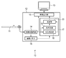
以下、本発明の実施の形態を、図面を参照して説明する。図1は、本発明の一実施形態である画像処理装置が搭載された電子内視鏡システムの構成を示すブロック図である。なお、図1では、画像処理に係る構成のみが示される。 Hereinafter, embodiments of the present invention will be described with reference to the drawings. FIG. 1 is a block diagram showing a configuration of an electronic endoscope system equipped with an image processing apparatus according to an embodiment of the present invention. In FIG. 1, only the configuration related to image processing is shown.
電子内視鏡システム10は、スコープ11、プロセッサ装置12、モニタ装置13を備え、スコープ11およびモニタ装置13は、プロセッサ装置12に着脱自在に装着される。スコープ11の挿入部先端に設けられた撮像素子(図示せず)からの画像信号は、プロセッサ装置12内の映像処理回路14に入力され、例えば増幅処理、色変換処理、ホワイトバランス処理、ガンマ補正処理などの所定の処理が施された後、デジタル画像信号(画像データ)に変換される。
The
本実施形態のプロセッサ装置12は、スコープ11で撮影された通常の内視鏡画像をそのまま出力する通常画像表示モードと、内視鏡画像の各部が病変部に対応するか否かを評価し、それを反映した画像を出力する病変危険度表示モードとを備える。本実施形態において、映像処理回路14は、選択されたモードに応じて、映像出力部15、あるいは画像メモリ16および病変部検出部17の何れかに選択的にデジタル画像信号を出力する。
The
すなわち、通常画像表示モードでは、映像処理回路14はデジタル画像信号を直接映像出力部15へ出力し、病変危険度表示モードではメモリ16および病変部検出部17へ出力する。病変部検出部17では、画像メモリ16および映像処理回路14からの画像信号に基づき例えば各画素を危険度に応じて色分けした画像を生成し(後述)、映像出力部15へ出力する。映像出力部15は、映像処理回路14または病変部検出部17の何れかから入力されたデジタル画像信号を所定規格の映像信号に変換し、例えばモニタ装置13へと出力する。
That is, in the normal image display mode, the
また、病変部検出部17は、凹凸判定部18、色判定部19、および統合部20を備える。映像処理回路14からのデジタル画像信号は、凹凸判定部18と色判定部19とにそれぞれ入力される。一方、画像メモリ16に記憶されたデジタル画像信号は、病変検出部17に入力される。凹凸判定部18では入力されたデジタル画像に基づいて例えば脳回転状模様の有無を判定して、各画素の危険度を評価し、色判定部19では入力されたデジタル画像の色情報から各画素の危険度を評価する。
In addition, the
凹凸判定部18での評価、および色判定部19での評価は、それぞれ統合部20へ出力される。統合部20ではこれらの評価に基づき各画素の危険度が総合的に評価され、この評価を反映したデジタル画像が生成され、映像出力部15へと出力される。
The evaluation by the
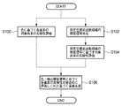
図2は、上述した病変部検出部17における処理の全体的な流れを説明するフローチャートである。ステップS100は、色判定部19において行われる処理であり、色情報に基づき各画素の危険度が評価される。これと並行して、凹凸判定部18ではステップS102、104が順次実行される。
FIG. 2 is a flowchart for explaining the overall flow of processing in the above-described lesioned
まず、ステップS102では、入力された画像信号から所定の空間周波数領域に対応する輝度信号を抽出する。その後ステップS104では、抽出された所定空間周波数領域の輝度信号に基づいて各画素の危険度が評価される。 First, in step S102, a luminance signal corresponding to a predetermined spatial frequency region is extracted from the input image signal. In step S104, the risk level of each pixel is evaluated based on the extracted luminance signal in the predetermined spatial frequency region.
ステップS106は、統合部20で実行される処理であり、ステップS100、ステップS104で得られた評価に基づき、各画素の危険性を総合的に評価するとともにその評価を反映した画像を生成する。なお統合部20でステップS106の処理が終了すると本処理終了するが、終了時、生成された画像信号は、映像出力部15へと出力される。
Step S106 is a process executed by the
次に図3〜図8を参照して、図2のステップS102における所定空間周波数領域の輝度信号の抽出方法について説明する。 Next, with reference to FIGS. 3 to 8, a method for extracting a luminance signal in the predetermined spatial frequency region in step S <b> 102 of FIG. 2 will be described.
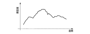
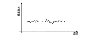
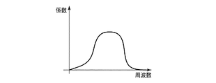
図3は、映像処理回路14から入力される輝度信号の一例を示すグラフであり、横軸は例えば画像の水平(垂直)ラインに沿った座標(例えばピクセルまたは画素ピッチを単位とする座標)、縦軸は輝度値である。図4は、図3の輝度信号に図7のバンドパスフィルタを施した輝度信号のグラフであり、腸管などの概形や粘膜表面の細かな凹凸形状を抽出するために図3の輝度信号から中域〜高域の空間周波数領域を抽出している。なお、バンドパスフィルタの適応においては、周波数空間の原点はそのまま透過させている。
FIG. 3 is a graph showing an example of a luminance signal input from the
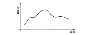
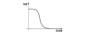
一方、図5は、図3の輝度信号に図8のローパスフィルタを施した輝度信号のグラフであり、ノイズを低減し、腸管などのヒダや腫瘍などの大まかな膨らみをもつ形状を抽出するために図3の輝度信号から低周波領域を抽出している。本実施形態では、図4の中〜高周波領域の輝度信号と図5の低周波域の輝度信号の差分をとることで、粘膜表面のテクスチャ情報のみを抽出した信号(所定周波数領域の輝度信号)を生成する。なお、各フィルタは水平・垂直両方向に沿って施される。 On the other hand, FIG. 5 is a graph of the luminance signal obtained by applying the low-pass filter of FIG. 8 to the luminance signal of FIG. 3, in order to reduce noise and extract a shape having a rough bulge such as a fold or tumor of the intestinal tract. In addition, a low frequency region is extracted from the luminance signal of FIG. In the present embodiment, a signal obtained by extracting only the texture information on the mucosal surface by taking the difference between the luminance signal in the middle to high frequency region of FIG. 4 and the luminance signal in the low frequency region of FIG. 5 (luminance signal in the predetermined frequency region). Is generated. Each filter is applied along both the horizontal and vertical directions.
図6に図4の中〜高周波数領域の輝度信号と図5の低周波域の輝度信号の差分をとることで粘膜表面のテクスチャ情報のみを抽出し、抽出された信号をプラス方向に一定量シフトしてマイナス成分を無くしたものが示される。 6 shows the difference between the luminance signal in the middle to high frequency region of FIG. 4 and the luminance signal in the low frequency region of FIG. 5 to extract only the texture information on the mucosal surface, and a certain amount of the extracted signal in the plus direction. Shown are those that have been shifted to eliminate the negative component.
次に図9を参照して、本実施形態における抽出された所定空間周波数領域の輝度信号に基づく各画素の病変部の可能性(危険性)評価方法、すなわち図2のステップS104の処理について説明する。 Next, with reference to FIG. 9, a description will be given of a method for evaluating the possibility (risk) of a lesion portion of each pixel based on the extracted luminance signal in the predetermined spatial frequency region in this embodiment, that is, the processing in step S104 in FIG. To do.
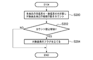
本処理では、ステップS200において各画素に対する前進差分および後進差分が計算され、対象画素(現在評価対象となっている画素)の周りの所定範囲に極値に対応する画素が幾つあるかがカウントされる。すなわち、前進後進差分で符号が入れ替わっている画素の数が対象画素を中心とする所定の範囲(例えば7×7画素)においてカウントされる。 In this process, the forward difference and the backward difference for each pixel are calculated in step S200, and the number of pixels corresponding to the extreme value in the predetermined range around the target pixel (the pixel currently being evaluated) is counted. The That is, the number of pixels whose codes are switched in the forward / backward difference is counted in a predetermined range (for example, 7 × 7 pixels) centered on the target pixel.
ステップS202では、ステップS200で算出された当該対象画素に関するカウント数が所定の閾値t1以上であるか否かが判定される。カウント数が閾値t1以上の場合には、対象画素周辺の粘膜表面に細かな凹凸形状(脳回転状模様など)が存在すると判断され、粘膜表面のテクスチャ情報からは対象画素は病変部に対応する可能性が高い。したがって、この場合にはステップS204において当該対象画素の危険度を示すフラグ(病変部である可能性を示すフラグ)が立てられこの処理は終了する。一方、ステップS202においてカウント数が閾値t1よりも小さいと判定される場合には、テクスチャ情報から当該画素の周辺部が病変部である可能性は低いので、当該対象画素のフラグを立てることなく本処理は終了する。 In step S202, it is determined whether or not the count for the target pixel calculated in step S200 is equal to or greater than a predetermined threshold t1. When the count number is equal to or greater than the threshold value t1, it is determined that there is a fine uneven shape (such as a brain rotation pattern) on the mucosal surface around the target pixel, and the target pixel corresponds to the lesion from the texture information on the mucosal surface. Probability is high. Therefore, in this case, in step S204, a flag indicating the degree of risk of the target pixel (a flag indicating the possibility of being a lesion) is set, and this process ends. On the other hand, if it is determined in step S202 that the count number is smaller than the threshold value t1, it is unlikely that the peripheral portion of the pixel is a lesion from the texture information, so the flag of the target pixel is not set. The process ends.
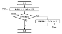
次に図10を参照して、図2のステップS100の処理における色情報に基づく各画素の病変部である危険性を評価方法について説明する。 Next, with reference to FIG. 10, a description will be given of a method for evaluating the risk of being a lesion part of each pixel based on the color information in the process of step S100 of FIG.
ステップS300では、各画素のRGB信号における画素値Gと画素値Rの比G/Rが計算され、ステップS302において対象画素のG/Rの値が所定の閾値t2以下であるか否かが判定される。G/Rが閾値t2以下の場合には、血液の色味が強いと判断されるので、色情報からは病変部である可能性が高い。したがって、G/Rが閾値t2以下と判定される場合には、ステップS304において当該対象画素の危険度を示すフラグが立てられる。一方、ステップS302において、G/Rの値が閾値t2よりも大きいと判定される場合には、色情報からは対象画素が病変部である可能性は低いので対象画素のフラグを立てることなく本処理は終了する。なお、判定にG信号とR信号の比を用いるのは、光量が違う場合の影響を無くすためである。 In step S300, the ratio G / R between the pixel value G and the pixel value R in the RGB signal of each pixel is calculated, and in step S302, it is determined whether or not the G / R value of the target pixel is equal to or less than a predetermined threshold value t2. Is done. When G / R is equal to or less than the threshold value t2, it is determined that the color of blood is strong, so that there is a high possibility of a lesion from the color information. Therefore, when it is determined that G / R is equal to or less than the threshold value t2, a flag indicating the risk level of the target pixel is set in step S304. On the other hand, if it is determined in step S302 that the value of G / R is larger than the threshold value t2, it is unlikely that the target pixel is a lesion from the color information, so the target pixel is not flagged. The process ends. The reason why the ratio of the G signal and the R signal is used for the determination is to eliminate the influence when the amount of light is different.
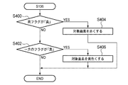
次に図11を参照して、図2のステップS106における色情報およびテクスチャ情報(輝度情報)を用いた各画素の病変部としての危険性の総合的な評価方法、および画像生成方法について説明する。 Next, with reference to FIG. 11, a comprehensive evaluation method and an image generation method for the risk of each pixel as a lesion using the color information and texture information (luminance information) in step S106 in FIG. 2 will be described. .
ステップS400、ステップS402では、順次対象画素毎にステップS100、ステップS104のフラグの内容が参照される。ステップS400では、対象画素に対する両フラグが「真」であるか否かが判定され、両フラグともに「真」の場合には、ステップS404において対象画素の色が例えば赤に設定され、本処理は終了する。 In steps S400 and S402, the contents of the flags in steps S100 and S104 are sequentially referred to for each target pixel. In step S400, it is determined whether or not both flags for the target pixel are “true”. If both flags are “true”, the color of the target pixel is set to, for example, red in step S404. finish.
一方、両フラグがともに「真」でない場合には、ステップS402において一方のフラグが「真」であるか否かが判定される。少なくとも一方のフラグが「真」のときには、ステップS406において対象画素の色が例えば黄色に設定され、本処理は終了する。また、ステップS402において両フラグともに「真」ではないと判定された場合には、対象画素の色は例えば黒に設定され本処理は終了する。 On the other hand, if both flags are not “true”, it is determined in step S402 whether one of the flags is “true”. When at least one of the flags is “true”, the color of the target pixel is set to, for example, yellow in step S406, and this process ends. If it is determined in step S402 that both flags are not “true”, the color of the target pixel is set to, for example, black, and this process ends.
すなわち、病変危険度表示モードでは、ステップS400〜S406を通して設定された各画素の色に基づいて画像信号が生成され映像出力部15(図1参照)を介してモニタ装置13に出力・表示される。
That is, in the lesion risk display mode, an image signal is generated based on the color of each pixel set through steps S400 to S406, and is output and displayed on the
以上のように、本実施形態によれば、色情報からではなく、病変部に特徴的なテクスチャ情報(脳回転状模様)からも内視鏡画像の各画素に対応する箇所が病変部である可能性を評価でき、より正確な評価が可能になる。また、色情報とテクスチャ情報を組み合わせて各画素が病変部である可能性を総合的、段階的に評価し、これを内視鏡画像に対応する画像として表示することができる。 As described above, according to the present embodiment, a portion corresponding to each pixel of the endoscopic image is a lesion portion not only from color information but also from texture information (brain rotation pattern) characteristic of the lesion portion. The possibility can be evaluated and a more accurate evaluation becomes possible. Further, it is possible to evaluate the possibility that each pixel is a lesioned part by combining color information and texture information in a comprehensive and stepwise manner, and display this as an image corresponding to an endoscopic image.
次に、本実施形態の第1変形例について説明する。上述した実施形態では、図2のステップS102において、ローパスフィルタ、バンドパスフィルタを用いて所定の空間周波数領域の輝度信号を取得したが、第1変形例では、例えば、図3の輝度信号に対して、分散が異なる2つのガウスフィルタを施す。すなわち、分散が相対的に小さいガウスフィルタにより図4に対応する輝度信号を生成し、分散が相対的に大きいガウスフィルタにより図5に対応する輝度信号を生成する。これらの差から図6に対応する輝度信号を生成し、実施形態と同様の方法で、各画素の危険度を評価し、画像を生成する。また、例えばステップS102において、画像信号に対し2次元フーリエ変換を施し、周波数空間において所定領域の信号を抽出し逆変換で得られた画像信号に対して、図2のステップS104以下の処理を実行してもよい。 Next, a first modification of the present embodiment will be described. In the above-described embodiment, the luminance signal in the predetermined spatial frequency region is acquired using the low-pass filter and the band-pass filter in step S102 of FIG. 2, but in the first modification, for example, for the luminance signal of FIG. Thus, two Gaussian filters having different dispersions are applied. That is, a luminance signal corresponding to FIG. 4 is generated by a Gaussian filter having a relatively small variance, and a luminance signal corresponding to FIG. 5 is generated by a Gaussian filter having a relatively large variance. A luminance signal corresponding to FIG. 6 is generated from these differences, and the risk level of each pixel is evaluated and an image is generated by the same method as in the embodiment. Further, for example, in step S102, the image signal is subjected to two-dimensional Fourier transform, a signal in a predetermined region in the frequency space is extracted, and the process after step S104 in FIG. 2 is performed on the image signal obtained by the inverse transform. May be.
次に、図2のステップS104のテクスチャ情報(輝度情報)に基づく各画素の病変部としての危険性の評価方法を変更した第2変形例について説明する。上記実施形態では、各画素の前進後進差分を計算し、極値の数から病変部としての可能性(危険性)の評価を行ったが、第2変形例では、所定空間周波数領域の輝度信号、例えば図6に示される一定量プラス側にシフトした輝度信号に対して複数の閾値を設定し、輝度信号と閾値との比較に基づいて危険度を評価する。 Next, a description will be given of a second modified example in which the method for evaluating the risk of each pixel as a lesion based on the texture information (luminance information) in step S104 in FIG. 2 is changed. In the above embodiment, the forward / backward difference of each pixel is calculated, and the possibility (risk) as a lesion is evaluated from the number of extreme values. In the second modification, the luminance signal in a predetermined spatial frequency region is used. For example, a plurality of threshold values are set for the luminance signal shifted to the positive side by a certain amount shown in FIG. 6, and the degree of risk is evaluated based on a comparison between the luminance signal and the threshold value.
例えば、本変形例では各画素の輝度値を閾値と比較して画素を複数のカテゴリ、例えばハレーション、腸管の表面構造(粘膜表面の模様)、その他(ノイズなど)に分類し、対象画素の周辺の所定領域内に含まれる各カテゴリの画素の割合から、対象画素が病変部である可能性を評価する。本変形例では、図6の輝度信号が第1閾値よりも大きい画素をハレーションに対応する画素とし、図6の輝度値が第1閾値よりも小さく、第1閾値よりも小さい第2閾値よりも大きい画素を腸管の表面構造に対応する画素とする。また、第2閾値よりも図6の輝度値が低い画素をその他の画素とする。 For example, in this modification, the luminance value of each pixel is compared with a threshold value, and the pixel is classified into a plurality of categories, for example, halation, intestinal surface structure (mucosal surface pattern), and others (noise, etc.) The possibility that the target pixel is a lesioned part is evaluated from the ratio of the pixels of each category included in the predetermined region. In this modification, a pixel whose luminance signal is larger than the first threshold in FIG. 6 is a pixel corresponding to halation, and the luminance value in FIG. 6 is smaller than the first threshold and smaller than the second threshold smaller than the first threshold. Let a large pixel be a pixel corresponding to the surface structure of the intestinal tract. Further, the pixel having the luminance value in FIG. 6 lower than the second threshold value is set as another pixel.
例えば、ザラザラした表面や脳回転状の表面構造を有する病変部では、一般的に細かい輝度変化や細かいハレーションが多く含まれると考えられる。そのため本変形例では、対象画素を中心とする所定範囲(例えば周辺7×7画素)におけるハレーション対応画素数(面積)や表面構造対応画素数(面積)の割合を参照して各対象画素の危険度を段階的(例えば5段階)に評価する。 For example, a lesion having a rough surface or a brain-rotating surface structure is generally considered to contain many fine luminance changes and fine halation. Therefore, in this modification, the risk of each target pixel is referred to by referring to the ratio of the number of halation-corresponding pixels (area) and the number of surface structure-corresponding pixels (area) in a predetermined range (for example, the periphery 7 × 7 pixels) centered on the target pixel The degree is evaluated in stages (for example, 5 levels).
例えば、第2変形例では、色情報(ステップS100の情報)を用いず、テクスチャ情報のみで各画素の危険度を次の(A)〜(E)の5段階で評価し画像を生成する。
(A)表面構造対応画素の割合が極めて高く、ハレーション対応画素も存在する場合には危険度が最大であると判断し、その画素の色を赤に設定する。
(B)表面構造対応画素の割合が相対的に高く((A)よりは低い)、ハレーション対応画素も存在する場合には危険度が大きいと判断し、その画素の色を黄色に設定する。
(C)表面構造対応画素の割合が相対的に中程度で、ハレーション対応画素も存在する場合には危険度も中程度であると判断し、その画素の色を緑に設定する。
(D)表面構造対応画素の割合が相対的に低く、ハレーション対応画素も殆ど存在しない場合には危険度は小さいと判断し、その画素の色を青に設定する。
(E)表面構造対応画素の割合が最小で、ハレーション対応画素も殆ど存在しない場合には危険度は極小と判断し、その画素の色を紫に設定する。
For example, in the second modified example, the color information (information in step S100) is not used, and the risk level of each pixel is evaluated in the following five stages (A) to (E) using only texture information, and an image is generated.
(A) When the ratio of the surface structure-corresponding pixel is extremely high and the halation-corresponding pixel is also present, it is determined that the degree of danger is maximum, and the color of the pixel is set to red.
(B) If the ratio of the surface structure-corresponding pixels is relatively high (lower than (A)) and there is also a halation-corresponding pixel, it is determined that the degree of danger is high, and the color of the pixel is set to yellow.
(C) When the ratio of the surface structure-corresponding pixels is relatively medium and there is a halation-corresponding pixel, it is determined that the degree of danger is medium, and the color of the pixel is set to green.
(D) When the ratio of the surface structure-corresponding pixels is relatively low and there are almost no halation-corresponding pixels, it is determined that the degree of danger is small, and the color of the pixel is set to blue.
(E) When the ratio of the surface structure-corresponding pixels is minimum and there are almost no halation-corresponding pixels, it is determined that the degree of danger is minimal, and the color of the pixel is set to purple.
また、色情報(ステップS100の情報)と組み合わせて評価する場合には、例えば、各評価において危険度を示すポイント(評価値)を各画素に対して与え、その合計から各画素における総合的な危険度を評価し、例えば5段階に分類して各画素の色を決定することもできる。 Further, when the evaluation is performed in combination with the color information (information in step S100), for example, a point (evaluation value) indicating the degree of risk in each evaluation is given to each pixel, and the total in each pixel is determined from the total. The degree of risk can be evaluated, and for example, the color of each pixel can be determined by classifying into five levels.
以上のように第1、第2変形例においても実施形態と同様の効果を得ることができる。なお、実施形態、第1、第2変形例に記載された各構成は、矛盾が生じない範囲で任意に組み合わせることができる。 As described above, also in the first and second modified examples, the same effect as in the embodiment can be obtained. In addition, each structure described in the embodiment, the first modification, and the second modification can be arbitrarily combined as long as no contradiction occurs.
また、本実施形態および変形例では、所定空間周波数領域の輝度信号をプラス側にシフトしているが、シフトせずに病変部の可能性(危険度)の評価に用いることも可能である。 Further, in the present embodiment and the modification, the luminance signal in the predetermined spatial frequency region is shifted to the plus side. However, the luminance signal can be used for evaluating the possibility (risk level) of the lesioned portion without being shifted.
また、画像データを記録して、本実施形態および変形例の処理を別途コンピュータにおいて実行することも可能である。 It is also possible to record image data and separately execute the processing of the present embodiment and the modified example on a computer.
10 電子内視鏡システム
11 スコープ
12 プロセッサ装置
13 モニタ装置
14 映像処理回路
15 映像出力部
16 画像メモリ
17 病変部検出部
18 凹凸判定部
19 色判定部
20 統合部
DESCRIPTION OF
Claims (12)
前記画像信号抽出手段により抽出された信号の対象画素周りにおける輝度値の変化に基づいて前記対象画素が病変部である可能性を評価する第1病変部評価手段と、
前記対象画素の色情報に基づき前記対象画素が病変部である可能性を評価する第2病変部評価手段と、
前記第1および第2病変部評価手段の評価結果に基づいて各画素の病変部である可能性を総合的に評価する第3病変部評価手段と
を備えることを特徴とする画像処理装置。 Image signal extracting means for extracting a signal in a predetermined spatial frequency region from the image signal;
A first lesion evaluation unit that evaluates the possibility that the target pixel is a lesion based on a change in luminance value around the target pixel of the signal extracted by the image signal extraction unit ;
A second lesion evaluation means for evaluating the possibility that the target pixel is a lesion based on the color information of the target pixel;
An image processing apparatus comprising: a third lesion part evaluation unit that comprehensively evaluates the possibility of being a lesion part of each pixel based on the evaluation results of the first and second lesion part evaluation units.
前記画像信号抽出手段が画像信号から所定空間周波数領域の信号を抽出する工程と、
前記第1病変部評価手段が前記画像信号抽出手段により抽出された信号の対象画素周りにおける輝度値の変化に基づいて前記対象画素が病変部である可能性を評価する工程と、
前記第2病変部評価手段が前記対象画素の色情報に基づき前記対象画素が病変部である可能性を評価する工程と、
前記第3病変部評価手段が前記第1および第2病変部評価手段の評価結果に基づいて各画素の病変部である可能性を総合的に評価する工程と
を備えることを特徴とする画像処理装置の作動方法。 A method of operating an image processing apparatus including an image signal extraction unit, a first lesion site evaluation unit, a second lesion site evaluation unit, and a third lesion site evaluation unit,
A step of said image signal extracting means for extracting a signal of a predetermined spatial frequency domain from the image signal,
A step of evaluating the possibility that the target pixel is a lesion part based on a change in luminance value around the target pixel of the signal extracted by the image signal extraction unit by the first lesion part evaluation unit ;
A step of evaluating the possibility that the target pixel is a lesion part based on the color information of the target pixel, wherein the second lesion part evaluation means;
A step of comprehensively evaluating the possibility that the third lesion part evaluation means is a lesion part of each pixel based on the evaluation results of the first and second lesion part evaluation means;
Method of operating an image processing apparatus, characterized in that it comprises a.
前記画像信号抽出手段により抽出された信号の対象画素周りにおける輝度値の変化に基づいて前記対象画素が病変部である可能性を評価する第2手順と、
前記対象画素の色情報に基づき前記対象画素が病変部である可能性を評価する第3手順と、
前記第2および第3手順における評価結果に基づいて各画素の病変部である可能性を総合的に評価する第4手順と
をコンピュータに実行させることを特徴とする画像処理用コンピュータプログラム。 A first procedure for extracting data of a predetermined spatial frequency region from image data;
A second procedure for evaluating the possibility that the target pixel is a lesion part based on a change in luminance value around the target pixel of the signal extracted by the image signal extraction unit ;
A third procedure for evaluating the possibility that the target pixel is a lesion based on the color information of the target pixel;
A computer program for image processing, which causes a computer to execute a fourth procedure for comprehensively evaluating the possibility of a lesion part of each pixel based on the evaluation results in the second and third procedures .
Priority Applications (1)
| Application Number | Priority Date | Filing Date | Title |
|---|---|---|---|
| JP2011012122A JP5581237B2 (en) | 2011-01-24 | 2011-01-24 | Image processing device, processor device for electronic endoscope, operation method of image processing device, and computer program for image processing |
Applications Claiming Priority (1)
| Application Number | Priority Date | Filing Date | Title |
|---|---|---|---|
| JP2011012122A JP5581237B2 (en) | 2011-01-24 | 2011-01-24 | Image processing device, processor device for electronic endoscope, operation method of image processing device, and computer program for image processing |
Publications (2)
| Publication Number | Publication Date |
|---|---|
| JP2012152284A JP2012152284A (en) | 2012-08-16 |
| JP5581237B2 true JP5581237B2 (en) | 2014-08-27 |
Family
ID=46834701
Family Applications (1)
| Application Number | Title | Priority Date | Filing Date |
|---|---|---|---|
| JP2011012122A Active JP5581237B2 (en) | 2011-01-24 | 2011-01-24 | Image processing device, processor device for electronic endoscope, operation method of image processing device, and computer program for image processing |
Country Status (1)
| Country | Link |
|---|---|
| JP (1) | JP5581237B2 (en) |
Cited By (1)
| Publication number | Priority date | Publication date | Assignee | Title |
|---|---|---|---|---|
| EP4533998A4 (en) * | 2022-05-30 | 2025-10-08 | Nec Corp | IMAGE PROCESSING DEVICE, IMAGE PROCESSING METHOD AND STORAGE MEDIUM |
Families Citing this family (7)
| Publication number | Priority date | Publication date | Assignee | Title |
|---|---|---|---|---|
| JP6580446B2 (en) * | 2015-10-09 | 2019-09-25 | サイバネットシステム株式会社 | Image processing apparatus and image processing method |
| WO2018043552A1 (en) * | 2016-08-31 | 2018-03-08 | Hoya株式会社 | Processor for electronic endoscope, and electronic endoscope system |
| US10646102B2 (en) | 2016-08-31 | 2020-05-12 | Hoya Corporation | Processor for electronic endoscope, and electronic endoscope system |
| US11589777B2 (en) | 2016-08-31 | 2023-02-28 | Hoya Corporation | Electronic endoscope processor and electronic endoscopic system |
| JP7346602B2 (en) * | 2020-01-21 | 2023-09-19 | オリンパス株式会社 | Endoscope system, endoscope processor, operating method of endoscope processor, and operating program of endoscope processor |
| JPWO2023054366A1 (en) * | 2021-10-01 | 2023-04-06 | ||
| CN120013906B (en) * | 2025-01-22 | 2025-10-31 | 郑州大学第一附属医院 | A method, system, and storage medium for intelligent analysis of complex aortic lesions |
Family Cites Families (5)
| Publication number | Priority date | Publication date | Assignee | Title |
|---|---|---|---|---|
| JPH03105483A (en) * | 1989-09-19 | 1991-05-02 | Olympus Optical Co Ltd | Endoscope device |
| JPH04200433A (en) * | 1990-11-29 | 1992-07-21 | Olympus Optical Co Ltd | Endoscope image processor |
| EP1862106A1 (en) * | 2005-03-22 | 2007-12-05 | Osaka University | Capsule endoscope image display controller |
| JP4855709B2 (en) * | 2005-04-27 | 2012-01-18 | オリンパスメディカルシステムズ株式会社 | Image processing apparatus, image processing method, and image processing program |
| JP5121204B2 (en) * | 2006-10-11 | 2013-01-16 | オリンパス株式会社 | Image processing apparatus, image processing method, and image processing program |
-
2011
- 2011-01-24 JP JP2011012122A patent/JP5581237B2/en active Active
Cited By (1)
| Publication number | Priority date | Publication date | Assignee | Title |
|---|---|---|---|---|
| EP4533998A4 (en) * | 2022-05-30 | 2025-10-08 | Nec Corp | IMAGE PROCESSING DEVICE, IMAGE PROCESSING METHOD AND STORAGE MEDIUM |
Also Published As
| Publication number | Publication date |
|---|---|
| JP2012152284A (en) | 2012-08-16 |
Similar Documents
| Publication | Publication Date | Title |
|---|---|---|
| JP5581237B2 (en) | Image processing device, processor device for electronic endoscope, operation method of image processing device, and computer program for image processing | |
| JP6112879B2 (en) | Image processing apparatus, endoscope apparatus, operation method of image processing apparatus, and image processing program | |
| JP4054184B2 (en) | Defective pixel correction device | |
| JP4914303B2 (en) | Image processing apparatus and imaging apparatus, image processing method and imaging method, and image processing program | |
| JP4882374B2 (en) | Image processing method, image processing program, and image processing apparatus | |
| JP5197414B2 (en) | Image processing apparatus and image processing method | |
| TWI333381B (en) | ||
| US12347066B2 (en) | Information processing system, endoscope system, and information storage medium | |
| JP2006297118A (en) | Method and system for detecting colorimetric anomalies in vivo | |
| EP2357799B1 (en) | Apparatus and method for removing defective pixels | |
| WO2008044466A1 (en) | Image processing device, image processing method, and image processing program | |
| JP6600936B2 (en) | Image processing apparatus, image processing method, image processing system, program, and recording medium | |
| CN102046062A (en) | Signal processing system and signal processing program | |
| CN111784686A (en) | Dynamic intelligent detection method, system and readable storage medium for endoscope bleeding area | |
| JP2010115243A (en) | Image signal processing apparatus for electronic endoscope | |
| WO2014013792A1 (en) | Noise evaluation method, image processing device, imaging device, and program | |
| JP5718138B2 (en) | Image signal processing apparatus and program | |
| US10158790B2 (en) | Image processing apparatus, image processing system, and image processing method | |
| JP7637683B2 (en) | Processor device and method for operating the processor device | |
| JP2009200635A (en) | Image processor, and processing method and program | |
| JP2007244589A (en) | Medical image processing apparatus and medical image processing method | |
| US20230030057A1 (en) | Processor device and method of operating the same | |
| CN116369824A (en) | An endoscope image processing system and algorithm | |
| JP2012000311A (en) | System and method for enhancing moving image | |
| JP2016082390A (en) | Signal processing device |
Legal Events
| Date | Code | Title | Description |
|---|---|---|---|
| A621 | Written request for application examination |
Free format text: JAPANESE INTERMEDIATE CODE: A621 Effective date: 20131118 |
|
| A977 | Report on retrieval |
Free format text: JAPANESE INTERMEDIATE CODE: A971007 Effective date: 20140319 |
|
| A131 | Notification of reasons for refusal |
Free format text: JAPANESE INTERMEDIATE CODE: A131 Effective date: 20140408 |
|
| A521 | Request for written amendment filed |
Free format text: JAPANESE INTERMEDIATE CODE: A523 Effective date: 20140604 |
|
| TRDD | Decision of grant or rejection written | ||
| A01 | Written decision to grant a patent or to grant a registration (utility model) |
Free format text: JAPANESE INTERMEDIATE CODE: A01 Effective date: 20140624 |
|
| A61 | First payment of annual fees (during grant procedure) |
Free format text: JAPANESE INTERMEDIATE CODE: A61 Effective date: 20140714 |
|
| R150 | Certificate of patent or registration of utility model |
Ref document number: 5581237 Country of ref document: JP Free format text: JAPANESE INTERMEDIATE CODE: R150 |
|
| S531 | Written request for registration of change of domicile |
Free format text: JAPANESE INTERMEDIATE CODE: R313531 |
|
| R350 | Written notification of registration of transfer |
Free format text: JAPANESE INTERMEDIATE CODE: R350 |
|
| R250 | Receipt of annual fees |
Free format text: JAPANESE INTERMEDIATE CODE: R250 |
|
| R250 | Receipt of annual fees |
Free format text: JAPANESE INTERMEDIATE CODE: R250 |
|
| R250 | Receipt of annual fees |
Free format text: JAPANESE INTERMEDIATE CODE: R250 |
|
| R250 | Receipt of annual fees |
Free format text: JAPANESE INTERMEDIATE CODE: R250 |
|
| R250 | Receipt of annual fees |
Free format text: JAPANESE INTERMEDIATE CODE: R250 |
|
| R250 | Receipt of annual fees |
Free format text: JAPANESE INTERMEDIATE CODE: R250 |
|
| R250 | Receipt of annual fees |
Free format text: JAPANESE INTERMEDIATE CODE: R250 |
|
| R250 | Receipt of annual fees |
Free format text: JAPANESE INTERMEDIATE CODE: R250 |
|
| R250 | Receipt of annual fees |
Free format text: JAPANESE INTERMEDIATE CODE: R250 |