JP5580399B2 - Supply circuit - Google Patents
Supply circuit Download PDFInfo
- Publication number
- JP5580399B2 JP5580399B2 JP2012501437A JP2012501437A JP5580399B2 JP 5580399 B2 JP5580399 B2 JP 5580399B2 JP 2012501437 A JP2012501437 A JP 2012501437A JP 2012501437 A JP2012501437 A JP 2012501437A JP 5580399 B2 JP5580399 B2 JP 5580399B2
- Authority
- JP
- Japan
- Prior art keywords
- circuit
- supply
- supply circuit
- switch
- coupled
- Prior art date
- Legal status (The legal status is an assumption and is not a legal conclusion. Google has not performed a legal analysis and makes no representation as to the accuracy of the status listed.)
- Expired - Fee Related
Links
Images


Classifications
-
- H—ELECTRICITY
- H02—GENERATION; CONVERSION OR DISTRIBUTION OF ELECTRIC POWER
- H02M—APPARATUS FOR CONVERSION BETWEEN AC AND AC, BETWEEN AC AND DC, OR BETWEEN DC AND DC, AND FOR USE WITH MAINS OR SIMILAR POWER SUPPLY SYSTEMS; CONVERSION OF DC OR AC INPUT POWER INTO SURGE OUTPUT POWER; CONTROL OR REGULATION THEREOF
- H02M3/00—Conversion of dc power input into dc power output
- H02M3/02—Conversion of dc power input into dc power output without intermediate conversion into ac
- H02M3/04—Conversion of dc power input into dc power output without intermediate conversion into ac by static converters
- H02M3/10—Conversion of dc power input into dc power output without intermediate conversion into ac by static converters using discharge tubes with control electrode or semiconductor devices with control electrode
- H02M3/145—Conversion of dc power input into dc power output without intermediate conversion into ac by static converters using discharge tubes with control electrode or semiconductor devices with control electrode using devices of a triode or transistor type requiring continuous application of a control signal
- H02M3/155—Conversion of dc power input into dc power output without intermediate conversion into ac by static converters using discharge tubes with control electrode or semiconductor devices with control electrode using devices of a triode or transistor type requiring continuous application of a control signal using semiconductor devices only
- H02M3/156—Conversion of dc power input into dc power output without intermediate conversion into ac by static converters using discharge tubes with control electrode or semiconductor devices with control electrode using devices of a triode or transistor type requiring continuous application of a control signal using semiconductor devices only with automatic control of output voltage or current, e.g. switching regulators
- H02M3/158—Conversion of dc power input into dc power output without intermediate conversion into ac by static converters using discharge tubes with control electrode or semiconductor devices with control electrode using devices of a triode or transistor type requiring continuous application of a control signal using semiconductor devices only with automatic control of output voltage or current, e.g. switching regulators including plural semiconductor devices as final control devices for a single load
-
- H—ELECTRICITY
- H02—GENERATION; CONVERSION OR DISTRIBUTION OF ELECTRIC POWER
- H02M—APPARATUS FOR CONVERSION BETWEEN AC AND AC, BETWEEN AC AND DC, OR BETWEEN DC AND DC, AND FOR USE WITH MAINS OR SIMILAR POWER SUPPLY SYSTEMS; CONVERSION OF DC OR AC INPUT POWER INTO SURGE OUTPUT POWER; CONTROL OR REGULATION THEREOF
- H02M3/00—Conversion of dc power input into dc power output
- H02M3/02—Conversion of dc power input into dc power output without intermediate conversion into ac
- H02M3/04—Conversion of dc power input into dc power output without intermediate conversion into ac by static converters
- H02M3/06—Conversion of dc power input into dc power output without intermediate conversion into ac by static converters using resistors or capacitors, e.g. potential divider
- H02M3/07—Conversion of dc power input into dc power output without intermediate conversion into ac by static converters using resistors or capacitors, e.g. potential divider using capacitors charged and discharged alternately by semiconductor devices with control electrode, e.g. charge pumps
-
- H—ELECTRICITY
- H05—ELECTRIC TECHNIQUES NOT OTHERWISE PROVIDED FOR
- H05B—ELECTRIC HEATING; ELECTRIC LIGHT SOURCES NOT OTHERWISE PROVIDED FOR; CIRCUIT ARRANGEMENTS FOR ELECTRIC LIGHT SOURCES, IN GENERAL
- H05B45/00—Circuit arrangements for operating light-emitting diodes [LED]
- H05B45/30—Driver circuits
- H05B45/37—Converter circuits
- H05B45/3725—Switched mode power supply [SMPS]
-
- H—ELECTRICITY
- H02—GENERATION; CONVERSION OR DISTRIBUTION OF ELECTRIC POWER
- H02M—APPARATUS FOR CONVERSION BETWEEN AC AND AC, BETWEEN AC AND DC, OR BETWEEN DC AND DC, AND FOR USE WITH MAINS OR SIMILAR POWER SUPPLY SYSTEMS; CONVERSION OF DC OR AC INPUT POWER INTO SURGE OUTPUT POWER; CONTROL OR REGULATION THEREOF
- H02M1/00—Details of apparatus for conversion
- H02M1/0048—Circuits or arrangements for reducing losses
- H02M1/0054—Transistor switching losses
- H02M1/0058—Transistor switching losses by employing soft switching techniques, i.e. commutation of transistors when applied voltage is zero or when current flow is zero
-
- Y—GENERAL TAGGING OF NEW TECHNOLOGICAL DEVELOPMENTS; GENERAL TAGGING OF CROSS-SECTIONAL TECHNOLOGIES SPANNING OVER SEVERAL SECTIONS OF THE IPC; TECHNICAL SUBJECTS COVERED BY FORMER USPC CROSS-REFERENCE ART COLLECTIONS [XRACs] AND DIGESTS
- Y02—TECHNOLOGIES OR APPLICATIONS FOR MITIGATION OR ADAPTATION AGAINST CLIMATE CHANGE
- Y02B—CLIMATE CHANGE MITIGATION TECHNOLOGIES RELATED TO BUILDINGS, e.g. HOUSING, HOUSE APPLIANCES OR RELATED END-USER APPLICATIONS
- Y02B20/00—Energy efficient lighting technologies, e.g. halogen lamps or gas discharge lamps
- Y02B20/30—Semiconductor lamps, e.g. solid state lamps [SSL] light emitting diodes [LED] or organic LED [OLED]
-
- Y—GENERAL TAGGING OF NEW TECHNOLOGICAL DEVELOPMENTS; GENERAL TAGGING OF CROSS-SECTIONAL TECHNOLOGIES SPANNING OVER SEVERAL SECTIONS OF THE IPC; TECHNICAL SUBJECTS COVERED BY FORMER USPC CROSS-REFERENCE ART COLLECTIONS [XRACs] AND DIGESTS
- Y02—TECHNOLOGIES OR APPLICATIONS FOR MITIGATION OR ADAPTATION AGAINST CLIMATE CHANGE
- Y02B—CLIMATE CHANGE MITIGATION TECHNOLOGIES RELATED TO BUILDINGS, e.g. HOUSING, HOUSE APPLIANCES OR RELATED END-USER APPLICATIONS
- Y02B70/00—Technologies for an efficient end-user side electric power management and consumption
- Y02B70/10—Technologies improving the efficiency by using switched-mode power supplies [SMPS], i.e. efficient power electronics conversion e.g. power factor correction or reduction of losses in power supplies or efficient standby modes
Description
本発明は、供給回路に係り、更に、供給回路を有する装置に係る。 The present invention relates to a supply circuit, and further to an apparatus having the supply circuit.
供給回路、特に、スイッチドモード電源は、当該技術においてよく知られている。かかる供給回路は、例えば、消費者製品及び非消費者製品に組み込まれている。例となる用途は、発光ダイオード(LED)及び/又は有機発光ダイオード(OLED)、特に、自動車用のLED/OLED照明及び一般的にバッテリ駆動のLED/OLED照明システムに使用されるLED/OLED列の給電である。 Supply circuits, particularly switched mode power supplies, are well known in the art. Such supply circuits are incorporated in, for example, consumer products and non-consumer products. Exemplary applications are light emitting diodes (LEDs) and / or organic light emitting diodes (OLEDs), in particular LED / OLED arrays used in automotive LED / OLED lighting and generally battery powered LED / OLED lighting systems. Power supply.
前述の用途に最も良く適しており、従って、該用途に望ましくは使用される供給回路は、特に、一定の平均電流出力を有する不連続直列共振コンバータ(discontinuous series resonant converter)(以下、DSRC−Iと称される。)である。このようなコンバータは、例えば、国際公開第2008/110978号パンフレット(特許文献1)に記載されている。このタイプのコンバータの機能性は、当業者によってよく理解されており、従って、より詳細には説明されない。DSRC−Iコンバータは、平均電流出力が一定であり、電流検知及び電流制御ループが必要とされないという利点を有する。結果として、電流検知によって引き起こされる損失は回避され、DSRC−Iは、他の一般的に知られている供給回路と比較して高効率で、小型で、且つ容易な設計を提供する。 The supply circuit that is best suited for the above-mentioned application and is therefore preferably used for that application is in particular a discontinuous series resonant converter (hereinafter DSRC-I) having a constant average current output. Is called). Such a converter is described in, for example, pamphlet of International Publication No. 2008/110978 (Patent Document 1). The functionality of this type of converter is well understood by those skilled in the art and is therefore not described in more detail. The DSRC-I converter has the advantage that the average current output is constant and no current sensing and current control loop is required. As a result, losses caused by current sensing are avoided, and DSRC-I provides a highly efficient, compact and easy design compared to other commonly known supply circuits.
基本的なDSRC−Iの欠点は、変圧器又は追加の構成要素(例えば、追加の倍圧器回路)が設けられない場合に、出力電圧が入力電圧よりも低くなければならない点である。しかし、いずれの解決法も空間を必要とし、且つ、回路の費用を増大させる。一例として、自動車のLEDバックライトは、直列に接続された複数のLEDから成り、自動車バッテリの12ボルトよりも大きい電圧を必要とする。例えば、直列に5個のLEDが接続されている場合には、5×3.3V=16.5Vが必要とされる。従って、DSRC−Iは、複数のLEDが直列に接続される必要があり、且つ、低い供給電圧しか利用可能でない場合に(例えば、自動車用途において)、問題を引き起こす。 A drawback of the basic DSRC-I is that the output voltage must be lower than the input voltage if no transformer or additional components (eg, an additional voltage doubler circuit) are provided. However, either solution requires space and increases the cost of the circuit. As an example, an automotive LED backlight consists of a plurality of LEDs connected in series and requires a voltage greater than the 12 volts of the automotive battery. For example, when 5 LEDs are connected in series, 5 × 3.3V = 16.5V is required. Thus, DSRC-I causes problems when multiple LEDs need to be connected in series and only a low supply voltage is available (eg, in automotive applications).
また、バッテリ駆動されるシステムは、しばしば、より高い出力電圧を達成するよう直列にセルをスタックする。しかし、セルの十分なスタッキングは、空間の不足により、多くの高電圧用途においては可能でない。 Also, battery-powered systems often stack cells in series to achieve higher output voltages. However, sufficient stacking of cells is not possible in many high voltage applications due to lack of space.
本発明の目的は、入力電圧よりも高い出力電圧が得られる供給回路を提供することである。本発明に従う昇圧機能を有する供給回路は、入力電圧を増大させる、すなわち、出力電圧を増大させて、バッテリセルの数を低減する。 An object of the present invention is to provide a supply circuit that can obtain an output voltage higher than an input voltage. The supply circuit having a boosting function according to the present invention increases the input voltage, that is, increases the output voltage, thereby reducing the number of battery cells.
本発明の態様に従って、
供給回路をDC電源へ結合する入力端子、
負荷回路を前記供給回路へ結合する2つの出力端子、
前記2つの出力端子の間に結合される少なくとも2つの直列接続されたスイッチを有するブリッジ回路、
一方の端部を1又はそれ以上の入力端子へ結合され、他方の端部を前記ブリッジ回路の前記少なくとも2つのスイッチの相互接続部へ結合される共振回路、及び
少なくとも2つのダイオード
を有し、
第1のダイオードは、前記電源の正極端子を結合するよう設けられている第1の入力端子と、第1の出力端子へ結合されている前記直列接続されたスイッチの第1端の端子との間に結合され、第2のダイオードは、前記電源の負極端子を結合するよう設けられている第2の入力端子と、第2の出力端子へ結合されている前記直列に接続されたスイッチの第2端の端子との間に結合される、供給回路が提供される。
According to an aspect of the invention,
An input terminal for coupling the supply circuit to a DC power source;
Two output terminals for coupling a load circuit to the supply circuit;
A bridge circuit having at least two series connected switches coupled between the two output terminals ;
A resonant circuit having one end coupled to one or more input terminals and the other end coupled to an interconnect of the at least two switches of the bridge circuit; and
Have at least two diodes,
The first diode includes a first input terminal provided to couple a positive terminal of the power source, and a first end terminal of the series-connected switch coupled to a first output terminal. And a second diode coupled between the second input terminal provided to couple the negative terminal of the power source and a second of the series connected switches coupled to the second output terminal. A supply circuit is provided that is coupled between the two end terminals .
このコンバータ・トポロジは、入力電圧よりも高い出力電圧で一定平均電流出力を供給する。更に、それは簡単な回路設計を有し、変圧器又は他の追加の構成要素を必要としない。要するに、コンバータは、電流検知及び電流制御が必要とされず、更に、極めてコンパクトな回路設計が昇圧を組み込むことで提供されるという利点を提供する。本発明に従う供給回路は、とりわけ、設計するのが容易であり、制御するのが簡単であり、且つ、高い効率を提供する。供給回路の詳細な機能は、図面に関連して説明される。 This converter topology provides a constant average current output with an output voltage higher than the input voltage. Furthermore, it has a simple circuit design and does not require a transformer or other additional components. In short, the converter offers the advantage that current sensing and current control is not required, and that a very compact circuit design is provided by incorporating a boost. The supply circuit according to the invention is, inter alia, easy to design, simple to control and provides high efficiency. The detailed function of the supply circuit will be described with reference to the drawings.
供給回路が与えられる本発明の第1の態様において、前記第1のダイオードは、負の(極性を有する)共振電流のフローが許容されるように、割り当てられているスイッチに対して極性を有し、前記第2のダイオードは、正の(極性を有する)共振電流のフローが許容されるように、割り当てられているスイッチに対して極性を有する。これは、正の電流のみが出力に流れるという利点を提供する。 In a first aspect of the invention in which a supply circuit is provided, the first diode has a polarity with respect to an assigned switch so that a negative (polar) resonant current flow is allowed. The second diode has a polarity with respect to the assigned switch so that a positive (polar) resonant current flow is allowed. This provides the advantage that only positive current flows to the output.
供給回路が与えられる本発明の更なる態様において、前記共振回路は、インダクタンス及びキャパシタンスを有する直列共振回路である。これは、DSRC−Iの有利な機能性及び零電流スイッチング(ZCS)(当該技術においてよく知られており、従って、これ以上は説明されない。)を確かにする点で、有利である。 In a further aspect of the invention in which a supply circuit is provided, the resonant circuit is a series resonant circuit having an inductance and a capacitance. This is advantageous in that it ensures the advantageous functionality of DSRC-I and zero current switching (ZCS), which is well known in the art and therefore will not be further described.
供給回路が与えられる本発明の更なる他の態様において、前記共振回路は、前記入力端子、すなわち、前記ダイオードと前記電源との間の相互接続部へ結合される。具体的に、共振キャパシタンスは、少なくとも2つの部分キャパシタンスに分けられ、夫々の部分キャパシタンスは、前記共振キャパシタンスの2分の1であり、前記入力端子、すなわち、前記ダイオード及び前記電源の相互接続部へ結合される。このトポロジは、昇圧機能が実現される点で有利であり、更に、共通のDSRC−Iの主たる利点が維持される。 In yet another aspect of the invention in which a supply circuit is provided, the resonant circuit is coupled to the input terminal, ie, the interconnection between the diode and the power source. Specifically, the resonant capacitance is divided into at least two partial capacitances, each partial capacitance being one-half of the resonant capacitance, to the input terminal, ie, the diode and the power supply interconnect. Combined. This topology is advantageous in that the boost function is realized, and further, the main advantage of the common DSRC-I is maintained.
供給回路が与えられる本発明の更なる態様において、前記少なくとも2つのスイッチは、MOSFETである。これは、MOSFETが上記の用途に適しており、更に、制御するのが容易である点で、有利である。 In a further aspect of the invention in which a supply circuit is provided, the at least two switches are MOSFETs. This is advantageous in that the MOSFET is suitable for the applications described above and is easy to control.
供給回路が与えられる本発明の更なる態様において、当該供給回路は、前記ブリッジ回路の最大スイッチング周波数を供給するよう構成される制御ユニットを更に有し、前記最大スイッチング周波数は、前記共振回路の共振周波数の10%から50%の範囲、特に、前記共振回路の共振周波数の2分の1の範囲にある。 In a further aspect of the invention in which a supply circuit is provided, the supply circuit further comprises a control unit configured to supply a maximum switching frequency of the bridge circuit, wherein the maximum switching frequency is a resonance of the resonance circuit. It is in the range of 10% to 50% of the frequency, in particular in the range of half the resonant frequency of the resonant circuit.
更に、前記制御ユニットは、最大50%のデューティサイクルを有して前記ブリッジ回路の前記スイッチのスイッチングを提供するよう構成される。実際上、厳密に50%のデューティサイクルは達成不可能であり、望ましくは、短い不感時間(dead-time)がハイサイド・スイッチとローサイド・スイッチとの間で実施されるべきであり、その時間は、望ましくは、100ナノ秒(ns)から1マイクロ秒(μs)の範囲にある。 Further, the control unit is configured to provide switching of the switch of the bridge circuit with a duty cycle of up to 50%. In practice, a strictly 50% duty cycle is not achievable and preferably a short dead-time should be implemented between the high-side switch and the low-side switch. Is desirably in the range of 100 nanoseconds (ns) to 1 microsecond (μs).
本発明の他の態様に従って、電源と、負荷回路と、該負荷回路に給電するための、本発明に従って提案される供給回路とを有する装置が提供される。当然に、当該装置は、前記供給回路自体と同じ利点を有している。当該装置は1又はそれ以上の負荷を有してよく、一方、負荷は1又はそれ以上のLED、OLED等を有し、当該装置は例えば照明ユニットであってよい。 According to another aspect of the present invention, there is provided an apparatus comprising a power source, a load circuit, and a supply circuit proposed according to the present invention for powering the load circuit. Of course, the device has the same advantages as the supply circuit itself. The device may have one or more loads, while the load has one or more LEDs, OLEDs, etc., and the device may be a lighting unit, for example.
望ましくは、出力フィルタが、前記供給回路と前記負荷回路との間に配置される。前記出力回路は、出力電圧を安定させ、従って、負荷電流のより低いDCリップルを保証する。前記出力フィルタは、単純に、前記負荷回路へ並列に結合されるキャパシタによって、実施されてよいが、より複雑なフィルタが可能である(例えば、当該技術において一般的に知られているような、1又はそれ以上のキャパシタ及び/又はインダクタンスを有する直列及び/又は並列回路を有するフィルタ)。 Preferably, an output filter is disposed between the supply circuit and the load circuit. The output circuit stabilizes the output voltage and thus ensures a lower DC ripple of the load current. The output filter may simply be implemented by a capacitor coupled in parallel to the load circuit, but more complex filters are possible (e.g., as generally known in the art, A filter having series and / or parallel circuits with one or more capacitors and / or inductances).
当然に、請求される装置は、従属請求項で定義される請求される供給回路と類似した及び/又は同じ望ましい実施形態を有する。 Naturally, the claimed apparatus has similar and / or the same preferred embodiments as the claimed supply circuit as defined in the dependent claims.
本発明のこれらの及び他の態様は、後述される実施形態から明らかであり、これらを参照して説明される。 These and other aspects of the invention will be apparent from and will be elucidated with reference to the embodiments described hereinafter.
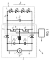
図1は、本発明の実施形態に従う供給回路1のブロック図を示す。供給回路1は、ブリッジ回路3と、一方の端部で、すなわち入力端子で、電源7へ結合可能である共振回路5とを有する。電源7は、望ましくは、直流電圧源Vinである。供給回路1は出力端子により負荷9へ結合されている。負荷9は、少なくとも1つの、図1においては例えば全部で4つの負荷11と、これらの負荷11へ並列に接続されている平滑キャパシタ13とを有する。負荷11はLED、OLED等であってよい。出力電圧Voutは、負荷11のアレイの両端で下がる。
FIG. 1 shows a block diagram of a
ブリッジ回路3は、制御ユニット14によって制御される少なくとも2つのスイッチM1及びM2(例えば、MOSFET)を有する。電源7からの直流電流に応答して、ブリッジ回路3は、スイッチング周波数fswitchで電圧信号を共振回路5へ伝え、次いで、共振回路5は、交流電流Irを負荷回路9へ伝える。
The
ブリッジ回路3のスイッチM1及びM2は、望ましくは、制御ユニット14によって切り換えられる。制御ユニット14は、50%のスイッチング・デューティサイクルを提供するよう構成される。更に、制御ユニット14は、ブリッジ回路3の最大スイッチング周波数fswitchを供給するよう構成される。最大スイッチング周波数fswitchは、望ましくは、共振回路5の共振周波数fresの2分の1である。
The switches M 1 and M 2 of the
スイッチM1及びM2は直列に接続されており、一方、スイッチM1のソース接点は、相互接続部15によってスイッチM2のドレイン接点へ結合されている。
Switches M 1 and M 2 are connected in series, while the source contact of switch M 1 is coupled by an
共振回路5は、一方の端部で電源7へ結合可能であり、他方の端部でブリッジ回路3の少なくとも2つのスイッチM1及びM2の相互接続部15へ結合される。共振回路5は、インダクタンスLres及びキャパシタンスCresを有し、キャパシタンスCresは、例えば、2つの部分共振キャパシタンスCres/2に分割されている。従って、部分キャパシタンスCres/2の夫々は、共振キャパシタンスCresの2分の1のキャパシタンスを有する。
The resonant circuit 5 can be coupled at one end to a power supply 7 and at the other end is coupled to an
更に、図1は、ダイオードD1がスイッチM1に割り当てられ、ダイオードD2がスイッチM2に割り当てられることを表す。具体的に、ダイオードD1及びD2は、夫々のスイッチM1及びM2と電源7との間に相互接続され、具体的に、一方で夫々の割り当てられているスイッチM1又はM2と直列に、他方で電源7へ接続されている。ダイオードの一方、特に、ダイオードD1は、ダイオードD1を通る負の(極性を有する)共振電流Irのフローが許容されるように、割り当てられているスイッチM1に対して極性を持たされ、他のダイオード、特に、ダイオードD2は、ダイオードD2を通る正の(極性を有する)共振電流Irが許容されるように、割り当てられているスイッチM2に対して極性を持たされている。 Furthermore, FIG. 1, the diode D 1 is assigned to the switch M 1, diode D 2 represents that assigned to the switch M 2. In particular, the diodes D 1 and D 2 are interconnected between the respective switches M 1 and M 2 and the power supply 7, in particular while the respective assigned switch M 1 or M 2 and In series, the other is connected to the power supply 7. One of the diodes, in particular, the diode D 1 (having a polarity) negative through diode D 1 as the flow of the resonant current I r is acceptable, which Motasa polarity to the switch M 1 assigned , other diodes, in particular, the diode D 2 (having a polarity) positive through diode D 2 resonance current as I r is permitted, is Motasa polarity to the switch M 2 assigned Yes.
以下でより詳細に説明されるように、共振回路5における電圧降下V1はダイオードに依存し、特に、どちらのダイオードが現在導通しているのかに依存する。従って、共振回路5における電圧降下は、次のようにまとめられる:M1がオンし且つD1が導通しているとき、電圧降下は−Vin/2であり、M1がD2に接続され且つD2が導通しているとき、電圧降下はVin/2−Voutであり、M2がD2に接続され且つD2が導通しているとき、電圧降下はVin/2であり、M2がオンし且つD1が導通しているとき、電圧降下は−Vin/2−Voutである。 As will be described in more detail below, the voltage drop V 1 of the resonant circuit 5 is dependent on the diode, in particular, which of the diode depends on whether they conducting current. Therefore, the voltage drop in the resonant circuit 5 is summarized as follows: when M1 is conducting is turned on and D 1, the voltage drop is -V in / 2, M 1 is connected to the D 2 and when D 2 is conducting, the voltage drop is V in / 2-V out, when M 2 is conductive and connected to and D 2 to D 2, the voltage drop is at V in / 2 when M 2 is conducting is turned on and D 1, the voltage drop is -V in / 2-V out.
部分キャパシタンスCres/2は、インダクタンスLresと直列に接続され、更に、ダイオードD1又はD2と電源7との間の相互接続部へ結合されている。このように、1つの部分キャパシタンスCres/2は、ダイオードD1と電源7との間の相互接続部17へ結合され、他の部分キャパシタンスCres/2は、ダイオードD2と電源との間の相互接続部19へ結合される。
The partial capacitance C res / 2 is connected in series with the inductance L res and is further coupled to the interconnection between the diode D 1 or D 2 and the power supply 7. In this way, one partial capacitance C res / 2 is coupled to the interconnect 17 between the diode D 1 and the power source 7 and the other partial capacitance C res / 2 is between the diode D 2 and the power source. To the
供給回路1の上記の新規なトポロジは、その主な利点の大部分を有するDSRC−Iを実現し、更に、昇圧機能を提供する。それにより、出力電圧Voutは、変圧器等の如何なる追加の構成要素も必要とせずに、入力電圧Vinよりも高くなる。
The above new topology of the
留意すべきは、本発明に従う装置21は、その供給回路1を有し、更に、1又はそれ以上の負荷回路9を有してよいことである。
It should be noted that the
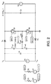
図2は、本発明の実施形態に従う供給回路1のシミュレーション回路図を示し、一方、図3乃至図6は、様々な組のパラメータ値についてのシミュレーション結果を示す。図2のシミュレーション回路は、図1に表されている供給回路トポロジに基づく。
FIG. 2 shows a simulation circuit diagram of the
図3は、第1の組のパラメータ値に係るシミュレーション結果を示す。具体的に、シミュレーション結果は、入力電圧Vin=24ボルト(V)と、出力電圧Vout=30Vと、ブリッジ回路のスイッチング周波数fswitch=fres/2(すなわち、スイッチング周波数は共振周波数fresの2分の1である。)とに基づく。 FIG. 3 shows the simulation results for the first set of parameter values. Specifically, the simulation result shows that the input voltage V in = 24 volts (V), the output voltage V out = 30 V, the switching frequency f switch = f res / 2 of the bridge circuit (that is, the switching frequency is the resonance frequency f res Is half of the above).
図3の一番上のシミュレーション図は、時間tの関数として電流I(V1)及びI(V4)を表す。それによって、電圧V1は、図1に表されている電圧Vinに対応し、電圧V2は、図1に表されている電圧Voutに対応する。出力電流I(V4)が入力電流I(V1)よりも低いことは明らかである。 The top simulation diagram of FIG. 3 represents currents I (V 1 ) and I (V 4 ) as a function of time t. Thereby, voltages V 1 corresponds to the voltage V in that is represented in Figure 1, the voltage V 2 corresponds to the voltage V out which is represented in FIG. It is clear that the output current I (V 4 ) is lower than the input current I (V 1 ).
図3の真ん中のシミュレーション図は、時間tの関数としてダイオード電流I(D1)及びI(D4)を表す。上述されたように、ダイオードD1及びD2は、反対の極性を有して、自身に割り当てられているスイッチM1及びM2に接続されている。従って、ダイオードD1及びD2は、後でより詳細に説明されるように、共振電流Irの極性に依存して、電流フローを交互に許容する。 The middle simulation diagram of FIG. 3 represents the diode currents I (D 1 ) and I (D 4 ) as a function of time t. As described above, the diode D 1 and D 2 have opposite polarities, are connected to the switches M 1 and M 2 are allocated to itself. Accordingly, the diode D 1 and D 2, as will be described in more detail below, depending on the polarity of the resonant current I r, to allow current flow alternately.
図3の一番下のシミュレーション図は、時間tの関数として共振電流I(Lres)を表す。共振電流I(Lres)は、図1の共振電流Irに対応する。 The bottom simulation diagram of FIG. 3 represents the resonance current I (L res ) as a function of time t. The resonance current I (L res ) corresponds to the resonance current I r in FIG.
図4は、第2の組のパラメータ値に係るシミュレーション結果を示す。具体的に、シミュレーション結果は、入力電圧Vin=24Vと、出力電圧Vout=40Vと、ブリッジ回路のスイッチング周波数fswitch=fres/2(すなわち、スイッチング周波数は共振周波数fresの2分の1である。)とに基づく。 FIG. 4 shows the simulation results for the second set of parameter values. Specifically, the simulation result shows that the input voltage V in = 24V, the output voltage V out = 40V, and the switching frequency f switch = f res / 2 of the bridge circuit (that is, the switching frequency is half of the resonance frequency f res 1).
図5は、第3の組のパラメータ値に係るシミュレーション結果を示す。具体的に、シミュレーション結果は、入力電圧Vin=24Vと、出力電圧Vout=50Vと、ブリッジ回路のスイッチング周波数fswitch=fres/2(すなわち、スイッチング周波数は共振周波数fresの2分の1である。)とに基づく。 FIG. 5 shows simulation results for the third set of parameter values. Specifically, the simulation result shows that the input voltage V in = 24 V, the output voltage V out = 50 V, the switching frequency f switch = f res / 2 of the bridge circuit (that is, the switching frequency is half of the resonance frequency f res ). 1).
図6は、第4の組のパラメータ値に係るシミュレーション結果を示す。具体的に、シミュレーション結果は、入力電圧Vin=24Vと、出力電圧Vout=40Vと、ブリッジ回路のスイッチング周波数fswitch=fres/3(すなわち、スイッチング周波数は共振周波数fresの3分の1である。)とに基づく。 FIG. 6 shows simulation results for the fourth set of parameter values. Specifically, the simulation result shows that the input voltage V in = 24V, the output voltage V out = 40V, and the switching frequency f switch = f res / 3 of the bridge circuit (that is, the switching frequency is a third of the resonance frequency f res 1).
供給回路1の機能性を記載するために、図1に示されるトポロジは、図7及び図8において表されるように簡単化されてよい。図7においては、2つのキャパシタンスCin1及びCin2と、更に、共振キャパシタンスCresとが設けられている。図8においては、図1の部分共振キャパシタンスCres/2は1つの単一キャパシタンスCresにまとめられており、電源7は、視覚的に、2つの部分電源7’及び7”に分割されている。夫々の部分電源は直流電圧Vin/2を供給する。留意すべきは、2つの部分キャパシタンスCres/2又は2つのキャパシタンスCin1及びCin2と、共振キャパシタンスCresとを用いることは、同じ結果をもたらす点である。図8から明らかなように、キャパシタンスCresの両端で起こる電圧降下はVCと表され、インダクタンスLresの両端で起こる電圧降下はVLと表される。
In order to describe the functionality of the
共振回路5は、その共振周波数fres及びその共振インピーダンスZresを用いて記載されてよい:
fres=1/(2π√(Lres・Cres)) (1)
Zres=√(Lres/Cres) (2)
シミュレーション結果に基づいて、回路動作は、次のように説明され得る。すなわち、説明のために、時間インターバルにおいて、共振周期の半分である周期τが定義される:
τ=(1/2)・Tres=(1/2)・(1/fres) (3)
スイッチM1及びM2のスイッチング周期は、図7から明らかなようにTswitchであり、2×Tres≦Tswitchである。夫々の時間インターバルにおける導通部分は、図9乃至図12に表される。
The resonant circuit 5 may be described using its resonant frequency f res and its resonant impedance Z res :
f res = 1 / (2π√ (L res · C res )) (1)
Z res = √ (L res / C res ) (2)
Based on the simulation results, the circuit operation can be described as follows. That is, for illustration purposes, a period τ is defined that is half the resonance period in the time interval:
τ = (1/2) · T res = (1/2) · (1 / f res ) (3)
The switching period of the switches M 1 and M 2 is T switch as is clear from FIG. 7, and 2 × T res ≦ T switch . The conduction part in each time interval is represented in FIGS.
図9は、図13に表される第1の時間インターバルt1:0<t≦τについて、本発明の実施形態に従う供給回路1の導通部分のブロック図を示す。この時間インターバルの間、スイッチM1はオンされ、スイッチM2はオフされる。共振回路5は、この時間インターバルにおいて、第1の負の正弦半波(図13においてW1により表される。)を生成する。
FIG. 9 shows a block diagram of the conducting portion of the
従って、スイッチM1は、直流電圧源7’から伝送される電流フローを可能にする。直列共振回路3、すなわち、Cres及びインダクタンスLresで生じる電圧降下は、図9において、V1により表されている。
Accordingly, the switch M 1 allows for current flow to be transmitted from the DC voltage source 7 '. The voltage drop caused by the series
結果として現れる電流Irは負であるから、ダイオードD1はこの電流に対して導通する。ダイオードD2は、ダイオードD1とは反対の極性を有しているので、第1の時間インターバルにおいては、負の電流Irのフローを許容しない。 Since as a result appears current I r is negative, the diode D 1 conducts against this current. Diode D 2, since a polarity opposite to the diodes D 1, in the first time interval, does not allow the flow of negative current I r.
シミュレーション結果に基づき、夫々の時間インターバルにおいて導通する構成要素が知られ、夫々の正弦半波の振幅が計算され得る。理想的な回路から、第1の時間インターバルt1の開始時に共振回路で起こる電圧降下(図8においてVC(t)と表される。)が計算され得る。その結果は:
VC(t=0)=Vout−Vin (4)
である。更に、Cres及びLresでの電圧降下V1が図9から求められる。すなわち、初期条件及び共振キャパシタの電圧VCを用いて、夫々のサイクルが終わった後の夫々の正弦半波の振幅及びキャパシタの電圧VCが計算され得る。サイクルごとに、共振回路全体に印加される電圧V1は、導通部分から求められ得る。第1のサイクルに関しては、V1は:
V1(0<t≦τ)=−Vin/2 (5)
である。理想的な回路動作に基づき、結果として得られる第1の負の正弦半波W1の振幅が計算され得る:
Based on the simulation results, the components that are conducting in each time interval are known and the amplitude of each half-sine wave can be calculated. From the ideal circuit, the voltage drop (denoted as V C (t) in FIG. 8) that occurs in the resonant circuit at the start of the first time interval t 1 can be calculated. The result is:
V C (t = 0) = V out −V in (4)
It is. Furthermore, the voltage drop V 1 at C res and L res is determined from FIG. That is, using a voltage V C of the initial conditions and the resonant capacitor, the amplitude and the voltage V C of the capacitor of the sinusoidal half wave of each of after each cycle has been completed can be calculated. For each cycle, the voltage V 1 applied across the resonant circuit can be determined from the conducting portion. For the first cycle, V 1 is:
V 1 (0 <t ≦ τ) = − V in / 2 (5)
It is. Based on the ideal circuit operation, the first negative amplitude of sine half wave W 1 resulting it can be calculated:

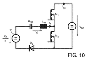
図10は、第2の時間インターバルt2:τ<t≦Tswitch/2について、本発明の実施形態に従う供給回路1の導通部分のブロック図を示す。この時間インターバルの間、スイッチM1は依然としてオンされ、スイッチM2は依然としてオフされる。共振回路5は、この時間インターバルにおいて、第2の正の正弦半波(図13においてW2により表される。)を生成する。
FIG. 10 shows a block diagram of the conducting portion of the
従って、電流Irは、このようにして、この時間インターバルt2の間、正である。結果として、ダイオードD1は電流フローを許容せず、従って、正の電流Irをブロックする。しかし、ダイオードD1とは反対の極性を有するダイオードD2は、正の電流Irのフローを許容する。図10から明らかなように、電流Ioutが出力を流れる。 Accordingly, the current I r is, in this way, during this time interval t 2, is positive. As a result, the diode D 1 will not allow current flow, thus blocking the positive current I r. However, the diode D 2 of opposite polarity to the diode D 1 allows the flow of positive current I r. As is apparent from FIG. 10, the current Iout flows through the output.
第一のインターバルt1の式による計算から、共振キャパシタ電圧VC(t)は:
VC(t=τ)=−Vout (7)
である。そして、V1は:
V1(τ<t≦Tswitch/2)=(Vin/2)−Vout (8)
である。これは、第2の正の正弦半波W2の振幅をもたらす:
From the calculation according to the equation for the first interval t 1 , the resonant capacitor voltage V C (t) is:
V C (t = τ) = − V out (7)
It is. And V 1 is:
V 1 (τ <t ≦ T switch / 2) = (V in / 2) −V out (8)
It is. This results in the amplitude of the sine half wave W 2 of the second positive:
図11は、第3の時間インターバルt3:Tswitch/2<t≦Tswitch/2+τについて、本発明の実施形態に従う供給回路1の導通部分のブロック図を示す。この時間インターバルの間、スイッチM1はオフされ、スイッチM2はオンされる。共振回路5は、この時間インターバルにおいて、第3の正の正弦半波(図13においてW3により表される。)を生成する。
FIG. 11 shows a block diagram of the conducting portion of the
従って、電流Irは、このようにして、この時間インターバルt3の間、正である。結果として、ダイオードD1は電流フローを許容せず、従って、正の電流Irをブロックする。しかし、ダイオードD1とは反対の極性を有するダイオードD2は、正の電流Irのフローを許容する。 Accordingly, the current I r is, in this way, during this time interval t 3, is positive. As a result, the diode D 1 will not allow current flow, thus blocking the positive current I r. However, the diode D 2 of opposite polarity to the diode D 1 allows the flow of positive current I r.
第3の時間インターバルt3及び第4の時間インターバルt4における動作は、第1の時間インターバルt1及び第2の時間インターバルt2の動作と同様である。基本的に、電流半波は、反対の符号を有して起こる。 Operation in the third time interval t 3, and the fourth time interval t 4 is the same as the first time interval t 1 and the second time interval t 2 operation. Basically, the current half-wave occurs with the opposite sign.
第3の時間インターバルt3の開始時のキャパシタ電圧VC(t)は:
VC(t=Tswitch/2)=Vin−Vout (10)
である。そして、V1は:
V1(Tswitch/2<t≦Tswitch/2+τ)=Vin/2 (11)
である。結果として、第3の正の正弦半波W3は、以下の振幅を有する:
The capacitor voltage V C (t) at the start of the third time interval t 3 is:
V C (t = T switch / 2) = V in −V out (10)
It is. And V 1 is:
V 1 (T switch / 2 <t ≦ T switch / 2 + τ) = V in / 2 (11)
It is. As a result, a third positive sine half wave W 3 being has the following amplitude:
従って、電流Irは、このようにして、この時間インターバルt4の間、負である。結果として、ダイオードD1は負の電流Irの電流フローを許容する。しかし、ダイオードD1とは反対の極性を有するダイオードD2は、負の電流Irの電流フローを許容しない。図12から明らかなように、電流Iresは再び出力と流れる。 Accordingly, the current I r is, in this way, during this time interval t 4, is negative. As a result, the diode D 1 permits a current flow a negative current I r. However, the diode D 2 of opposite polarity to the diode D 1 does not allow current flow a negative current I r. As is clear from FIG. 12, the current I res flows again with the output.
最終的に、第4の時間インターバルt4の開始時のキャパシタ電圧VC(t)は:
VC(t=Tswitch/2+τ)=Vout (13)
である。そして、V1は:
V1(Tswitch/2+τ<t≦Tswitch)=−Vin/2+Vout (14)
である。結果として、第4の負の正弦半波W4は、以下の振幅を有する:
Finally, the capacitor voltage V C (t) at the start of the fourth time interval t 4 is:
V C (t = T switch / 2 + τ) = V out (13)
It is. And V 1 is:
V 1 (T switch / 2 + τ <t ≦ T switch ) = − V in / 2 + V out (14)
It is. As a result, a fourth negative sine half wave W 4 of the has the following amplitude:
この夫々の半波は、図13の第1の半波W1について言及する場合、例えば、I1=(−Vout+Vin/2)Zresである。キャパシタンスCresでの電圧降下に係る初期条件と、共振回路5での電圧降下V1とを考慮すると、第1の半波W1の後のキャパシタンスCresでの電圧降下の量は、出力電圧Voutに等しい。従って、その後の半波W2に関しては、利用可能な電圧は、キャパシタンスCresの両端でのVoutに対応する電圧降下及び入力電圧の半分の電圧Vin/2の直列接続から得られる。 Each of these half-waves is, for example, I 1 = (− V out + V in / 2) Z res when referring to the first half-wave W 1 in FIG. Considering the initial conditions for the voltage drop at the capacitance C res and the voltage drop V 1 at the resonant circuit 5, the amount of voltage drop at the capacitance C res after the first half wave W 1 is the output voltage. Equal to Vout . Thus, for the subsequent half wave W 2 , the available voltage is obtained from a series connection of a voltage drop corresponding to V out across the capacitance C res and a voltage V in / 2 that is half the input voltage.
sかし、出力電圧Voutは、常に、第2の半波W2に逆らった振る舞いをとるので、入力電圧の半分の電圧、すなわち、Vin/2は常に残り、電流フローを負荷に流す。結果として、第2及び第4の半波W2及びW4は負荷を流れ、電流の振幅は、負荷電圧が入力電圧Vinよりも大きい場合において、負荷電圧に依存しない。 However, since the output voltage V out always behaves against the second half-wave W 2 , half the input voltage, ie, V in / 2, always remains and flows current flow to the load. . As a result, the second and fourth half wave W 2 and W 4 of the flow load, the amplitude of the current, when the load voltage is greater than the input voltage V in, does not depend on the load voltage.
結果として、本発明は、供給回路1、特に、自動車用LED/OLEDのために、又は、一般的に、DSRC−Iのみを構成要素としない場合に、バッテリ駆動のLED/OLED照明に使用可能なコンバータ・トポロジを提供する。これは、望ましくは、上記の用途に使用されるが、発明のトポロジにより、供給回路1は、更に、追加の構成要素を必要とすることなく、入力電圧Vinよりも高い出力電圧Voutを供給する昇圧機能を提供する。とりわけ、LED/OLEDの調光は、スイッチング周波数fswitchを低減することによって、実現され得る。スイッチング周波数が低減された場合における波形は、図6に示されている。
As a result, the present invention can be used for battery-powered LED / OLED lighting for the
更なる実施形態において、制御ループ、すなわち、フィードバックループが更に設けられてよい。フィードバックループは、例えば、LED電流又は電圧を測定し、この信号をコントローラへ送り、電子スイッチの制御信号を然るべく調整する。 In a further embodiment, a control loop, i.e. a feedback loop, may further be provided. The feedback loop, for example, measures the LED current or voltage and sends this signal to the controller to adjust the electronic switch control signal accordingly.
要約すると、本発明に従う共振回路の新規なトポロジは、基本的な、従来のDSRC−Iコンバータと同じ主たる利点を提供するが、更には、入力電圧Vinよりも高い出力電圧Voutを供給する。 Supplies summary, the novel topology of the resonant circuit according to the invention is basic, but provides the same main advantage to conventional DSRC-I converter, further, a high output voltage V out than the input voltage V in .
新規な共振回路は、入力電圧Vinよりも低い出力電圧Voutに関して、2つのダイオードD1及びD2に対する導通部分のために、不利であると考えられうるが、実際には、特定のLEDにおいて接続されている負荷の電圧が高い出力電圧Voutを生じさせるので、そのような問題は起こらない。このことは、コンバータが制御されない場合には、電流フローをブロックする。 The novel resonant circuit may be considered disadvantageous for the output voltage V out lower than the input voltage V in due to the conducting part for the two diodes D 1 and D 2 , but in practice certain LED Such a problem does not occur because the voltage of the load connected at 生 じ produces a high output voltage Vout . This blocks current flow when the converter is not controlled.
要するに、コンバータは、電流検知及び電流制御が必要とされず、更に、極めてコンパクトな回路設計が昇圧を組み込むことで提供されるという利点を提供する。本発明に従う供給回路は、とりわけ、設計するのが容易であり、制御するのが簡単であり、且つ、高い効率を提供する。当然に、同じ利点は、供給回路を有する本発明に従う装置についても当てはまる。 In short, the converter offers the advantage that current sensing and current control is not required, and that a very compact circuit design is provided by incorporating a boost. The supply circuit according to the invention is, inter alia, easy to design, simple to control and provides high efficiency. Of course, the same advantages also apply for a device according to the invention having a supply circuit.
以上の記載及び図面において本発明について詳細に説明してきたが、そのような記載は単なる例示であって限定ではないと解されるべきである。すなわち、本発明は、開示されている実施形態に限定されない。開示されている実施形態にする他の変形は、図面、本明細書、及び添付の特許請求の範囲を鑑みて当業者によって理解され実施可能である。 While the invention has been described in detail in the foregoing description and drawings, it should be understood that such description is merely illustrative and not limiting. The invention is not limited to the disclosed embodiments. Other variations to the disclosed embodiments can be understood and implemented by those skilled in the art in view of the drawings, the specification, and the appended claims.
特許請求の範囲において、語「有する(comprising)」は他の要素又はステップを排除せず、不定冠詞「1つの(a又はan)」は複数個を排除しない。単一の要素又は他のユニットが、特許請求の範囲に記載されている複数の事項の機能を満たしてよい。特定の手段が相互に異なる従属請求項に挙げられているという単なる事実は、それらの手段の組合せが有利に使用され得ないことを示すものではない。 In the claims, the word “comprising” does not exclude other elements or steps, and the indefinite article “a” or “an” does not exclude a plurality. A single element or other unit may fulfill the functions of several items recited in the claims. The mere fact that certain measures are recited in mutually different dependent claims does not indicate that a combination of these measured cannot be used to advantage.
特許請求の範囲における如何なる参照符号も、適用範囲を限定するものと解されるべきではない。 Any reference signs in the claims should not be construed as limiting the scope.
Claims (9)
当該供給回路を、DC入力電圧を供給するDC電源へ結合する入力端子であって、前記電源の正極端子を結合するよう設けられている第1の入力端子と、前記電源の負極端子を結合するよう設けられている第2の入力端子と、前記電源の中間端子を結合するよう設けられている第3の入力端子とを有する前記入力端子、
出力電圧を供給するよう負荷回路を当該供給回路へ結合する2つの出力端子、
前記2つの出力端子の間に結合される少なくとも2つの直列接続されたスイッチを有するブリッジ回路、
一方の端部を前記第3の入力端子へ結合され、他方の端部を前記ブリッジ回路の前記少なくとも2つのスイッチの相互接続部へ結合される共振回路、及び
少なくとも2つのダイオード
を有し、
第1のダイオードは、前記電源の正極端子を結合するよう設けられている前記第1の入力端子と、第1の出力端子へ結合されている前記直列接続されたスイッチの第1端の端子との間に順方向において結合され、第2のダイオードは、前記電源の負極端子を結合するよう設けられている前記第2の入力端子と、第2の出力端子へ結合されている前記直列に接続されたスイッチの第2端の端子との間に逆方向において結合される、供給回路。 A supply circuit for boosting a DC input voltage to a higher output voltage,
The supply circuit, an input terminal connected to a DC power source for supplying a DC input voltage, coupling a first input terminal provided to couple the positive terminal of the power source, the negative terminal of the power supply The input terminal having a second input terminal provided so as to be coupled to a third input terminal provided to couple an intermediate terminal of the power source ;
Two output terminals of the load circuit so as to supply the output voltage coupled to the supply circuit,
A bridge circuit having at least two series connected switches coupled between the two output terminals;
A resonant circuit having one end coupled to the third input terminal and the other end coupled to an interconnect of the at least two switches of the bridge circuit, and at least two diodes;
The first diode, said first input terminals provided to couple the positive terminal of the power source, a terminal of the first end of the series connected switch is coupled to the first output terminal coupled in the forward direction between the second diode, connected to said second input terminals provided to couple the negative terminal of the power supply, the series coupled to the second output terminal A supply circuit coupled in a reverse direction to a second terminal of the connected switch.
請求項1に記載の供給回路。 The first diode has a polarity with respect to the assigned switch so that a negative resonant current flow is allowed, and the second diode is allowed a positive resonant current flow So that it has polarity with respect to the assigned switch,
The supply circuit according to claim 1.
請求項1に記載の供給回路。 The resonant circuit is a series resonant circuit having an inductance and a capacitance.
The supply circuit according to claim 1.
請求項1に記載の供給回路。 The at least two switches are MOSFETs;
The supply circuit according to claim 1.
請求項1に記載の供給回路。 A control unit configured to supply a maximum switching frequency of the bridge circuit in a range of 10% to 50% of a resonance frequency of the resonance circuit;
The supply circuit according to claim 1.
請求項1に記載の供給回路。 A control unit configured to supply a maximum switching frequency of the bridge circuit that is in a range of one half of a resonance frequency of the resonance circuit;
The supply circuit according to claim 1.
請求項5に記載の供給回路。 The control unit is configured to provide switching of the switch of the bridge circuit with a duty cycle of up to 50%;
The supply circuit according to claim 5 .
請求項8に記載の装置。 An output filter between the supply circuit and the load circuit;
The apparatus according to claim 8 .
Applications Claiming Priority (3)
| Application Number | Priority Date | Filing Date | Title |
|---|---|---|---|
| EP09155842 | 2009-03-23 | ||
| EP09155842.9 | 2009-03-23 | ||
| PCT/IB2010/051109 WO2010109371A1 (en) | 2009-03-23 | 2010-03-15 | Supply circuit |
Publications (2)
| Publication Number | Publication Date |
|---|---|
| JP2012521628A JP2012521628A (en) | 2012-09-13 |
| JP5580399B2 true JP5580399B2 (en) | 2014-08-27 |
Family
ID=42102371
Family Applications (1)
| Application Number | Title | Priority Date | Filing Date |
|---|---|---|---|
| JP2012501437A Expired - Fee Related JP5580399B2 (en) | 2009-03-23 | 2010-03-15 | Supply circuit |
Country Status (9)
| Country | Link |
|---|---|
| US (1) | US9282600B2 (en) |
| EP (1) | EP2412205B1 (en) |
| JP (1) | JP5580399B2 (en) |
| KR (1) | KR20110131305A (en) |
| CN (1) | CN102362550B (en) |
| BR (1) | BRPI1006225A2 (en) |
| CA (1) | CA2756020A1 (en) |
| RU (1) | RU2518521C2 (en) |
| WO (1) | WO2010109371A1 (en) |
Families Citing this family (60)
| Publication number | Priority date | Publication date | Assignee | Title |
|---|---|---|---|---|
| US11881814B2 (en) | 2005-12-05 | 2024-01-23 | Solaredge Technologies Ltd. | Testing of a photovoltaic panel |
| US10693415B2 (en) | 2007-12-05 | 2020-06-23 | Solaredge Technologies Ltd. | Testing of a photovoltaic panel |
| US8816535B2 (en) | 2007-10-10 | 2014-08-26 | Solaredge Technologies, Ltd. | System and method for protection during inverter shutdown in distributed power installations |
| US8947194B2 (en) | 2009-05-26 | 2015-02-03 | Solaredge Technologies Ltd. | Theft detection and prevention in a power generation system |
| US8473250B2 (en) | 2006-12-06 | 2013-06-25 | Solaredge, Ltd. | Monitoring of distributed power harvesting systems using DC power sources |
| US8618692B2 (en) | 2007-12-04 | 2013-12-31 | Solaredge Technologies Ltd. | Distributed power system using direct current power sources |
| US11728768B2 (en) | 2006-12-06 | 2023-08-15 | Solaredge Technologies Ltd. | Pairing of components in a direct current distributed power generation system |
| US11888387B2 (en) | 2006-12-06 | 2024-01-30 | Solaredge Technologies Ltd. | Safety mechanisms, wake up and shutdown methods in distributed power installations |
| US11296650B2 (en) | 2006-12-06 | 2022-04-05 | Solaredge Technologies Ltd. | System and method for protection during inverter shutdown in distributed power installations |
| US8319483B2 (en) | 2007-08-06 | 2012-11-27 | Solaredge Technologies Ltd. | Digital average input current control in power converter |
| US11569659B2 (en) | 2006-12-06 | 2023-01-31 | Solaredge Technologies Ltd. | Distributed power harvesting systems using DC power sources |
| US9088178B2 (en) | 2006-12-06 | 2015-07-21 | Solaredge Technologies Ltd | Distributed power harvesting systems using DC power sources |
| US9112379B2 (en) | 2006-12-06 | 2015-08-18 | Solaredge Technologies Ltd. | Pairing of components in a direct current distributed power generation system |
| US8319471B2 (en) | 2006-12-06 | 2012-11-27 | Solaredge, Ltd. | Battery power delivery module |
| US9130401B2 (en) | 2006-12-06 | 2015-09-08 | Solaredge Technologies Ltd. | Distributed power harvesting systems using DC power sources |
| US8963369B2 (en) | 2007-12-04 | 2015-02-24 | Solaredge Technologies Ltd. | Distributed power harvesting systems using DC power sources |
| US8013472B2 (en) | 2006-12-06 | 2011-09-06 | Solaredge, Ltd. | Method for distributed power harvesting using DC power sources |
| US11735910B2 (en) | 2006-12-06 | 2023-08-22 | Solaredge Technologies Ltd. | Distributed power system using direct current power sources |
| US11309832B2 (en) | 2006-12-06 | 2022-04-19 | Solaredge Technologies Ltd. | Distributed power harvesting systems using DC power sources |
| US8384243B2 (en) | 2007-12-04 | 2013-02-26 | Solaredge Technologies Ltd. | Distributed power harvesting systems using DC power sources |
| US11687112B2 (en) | 2006-12-06 | 2023-06-27 | Solaredge Technologies Ltd. | Distributed power harvesting systems using DC power sources |
| US11855231B2 (en) | 2006-12-06 | 2023-12-26 | Solaredge Technologies Ltd. | Distributed power harvesting systems using DC power sources |
| JP2011507465A (en) | 2007-12-05 | 2011-03-03 | ソラレッジ テクノロジーズ リミテッド | Safety mechanism, wake-up method and shutdown method in distributed power installation |
| WO2009072076A2 (en) | 2007-12-05 | 2009-06-11 | Solaredge Technologies Ltd. | Current sensing on a mosfet |
| US8289742B2 (en) | 2007-12-05 | 2012-10-16 | Solaredge Ltd. | Parallel connected inverters |
| US11264947B2 (en) | 2007-12-05 | 2022-03-01 | Solaredge Technologies Ltd. | Testing of a photovoltaic panel |
| WO2009118683A2 (en) | 2008-03-24 | 2009-10-01 | Solaredge Technolgies Ltd. | Zero voltage switching |
| EP3719949A1 (en) | 2008-05-05 | 2020-10-07 | Solaredge Technologies Ltd. | Direct current power combiner |
| US9225254B2 (en) | 2009-02-26 | 2015-12-29 | Koninklijke Philips N.V. | Supply circuit having at least one switching unit coupled between a bridge circuit and an associated load circuit |
| WO2012056766A1 (en) * | 2010-10-27 | 2012-05-03 | 三菱電機株式会社 | Power conversion apparatus |
| US10673222B2 (en) | 2010-11-09 | 2020-06-02 | Solaredge Technologies Ltd. | Arc detection and prevention in a power generation system |
| US10230310B2 (en) | 2016-04-05 | 2019-03-12 | Solaredge Technologies Ltd | Safety switch for photovoltaic systems |
| US10673229B2 (en) | 2010-11-09 | 2020-06-02 | Solaredge Technologies Ltd. | Arc detection and prevention in a power generation system |
| GB2485527B (en) | 2010-11-09 | 2012-12-19 | Solaredge Technologies Ltd | Arc detection and prevention in a power generation system |
| GB2486408A (en) | 2010-12-09 | 2012-06-20 | Solaredge Technologies Ltd | Disconnection of a string carrying direct current |
| GB2483317B (en) | 2011-01-12 | 2012-08-22 | Solaredge Technologies Ltd | Serially connected inverters |
| US8570005B2 (en) | 2011-09-12 | 2013-10-29 | Solaredge Technologies Ltd. | Direct current link circuit |
| US8723491B2 (en) * | 2011-12-19 | 2014-05-13 | Arctic Sand Technologies, Inc. | Control of power converters with capacitive energy transfer |
| GB2498365A (en) | 2012-01-11 | 2013-07-17 | Solaredge Technologies Ltd | Photovoltaic module |
| GB2498791A (en) | 2012-01-30 | 2013-07-31 | Solaredge Technologies Ltd | Photovoltaic panel circuitry |
| GB2498790A (en) | 2012-01-30 | 2013-07-31 | Solaredge Technologies Ltd | Maximising power in a photovoltaic distributed power system |
| US9853565B2 (en) | 2012-01-30 | 2017-12-26 | Solaredge Technologies Ltd. | Maximized power in a photovoltaic distributed power system |
| GB2499991A (en) * | 2012-03-05 | 2013-09-11 | Solaredge Technologies Ltd | DC link circuit for photovoltaic array |
| US10115841B2 (en) | 2012-06-04 | 2018-10-30 | Solaredge Technologies Ltd. | Integrated photovoltaic panel circuitry |
| US9548619B2 (en) | 2013-03-14 | 2017-01-17 | Solaredge Technologies Ltd. | Method and apparatus for storing and depleting energy |
| US8619445B1 (en) | 2013-03-15 | 2013-12-31 | Arctic Sand Technologies, Inc. | Protection of switched capacitor power converter |
| EP3506370B1 (en) | 2013-03-15 | 2023-12-20 | Solaredge Technologies Ltd. | Bypass mechanism |
| EP2846608B1 (en) * | 2013-09-06 | 2016-06-01 | Tridonic GmbH & Co. KG | Converter and method of operating a converter for supplying current to a light emitting means |
| GB201319791D0 (en) * | 2013-11-08 | 2013-12-25 | Sigmoid Pharma Ltd | Formulations |
| WO2016146375A1 (en) * | 2015-03-17 | 2016-09-22 | Philips Lighting Holding B.V. | Driver with at least four different states |
| US11081608B2 (en) | 2016-03-03 | 2021-08-03 | Solaredge Technologies Ltd. | Apparatus and method for determining an order of power devices in power generation systems |
| US10599113B2 (en) | 2016-03-03 | 2020-03-24 | Solaredge Technologies Ltd. | Apparatus and method for determining an order of power devices in power generation systems |
| CN117130027A (en) | 2016-03-03 | 2023-11-28 | 太阳能安吉科技有限公司 | Method for mapping a power generation facility |
| US11018623B2 (en) | 2016-04-05 | 2021-05-25 | Solaredge Technologies Ltd. | Safety switch for photovoltaic systems |
| US11177663B2 (en) | 2016-04-05 | 2021-11-16 | Solaredge Technologies Ltd. | Chain of power devices |
| WO2018066444A1 (en) * | 2016-10-06 | 2018-04-12 | 株式会社村田製作所 | Dc-dc converter |
| US10038393B1 (en) * | 2017-11-02 | 2018-07-31 | National Chung-Shan Institute Of Science & Technology | Single-phase non-isolated inverter |
| WO2019145016A1 (en) | 2018-01-23 | 2019-08-01 | Huawei Technologies Co., Ltd. | Power converter |
| CN110649601B (en) * | 2019-09-20 | 2022-12-20 | 惠州市豪美仕智能技术有限公司 | Virtual parallel power taking method utilizing time division |
| RU200090U1 (en) * | 2020-08-07 | 2020-10-06 | Общество с ограниченной ответственностью "Калибр ТЗ" | Modular power supply |
Family Cites Families (17)
| Publication number | Priority date | Publication date | Assignee | Title |
|---|---|---|---|---|
| US4713220A (en) * | 1985-04-22 | 1987-12-15 | National Distillers And Chemical Corporation | Ozonator power supply |
| US4860184A (en) * | 1987-09-23 | 1989-08-22 | Virginia Tech Intellectual Properties, Inc. | Half-bridge zero-voltage switched multi-resonant converters |
| JP2677406B2 (en) * | 1989-01-26 | 1997-11-17 | 松下電工株式会社 | Power supply |
| JP2929635B2 (en) * | 1990-01-31 | 1999-08-03 | 東芝ライテック株式会社 | Power circuit |
| JPH04141992A (en) * | 1990-09-30 | 1992-05-15 | Toshiba Lighting & Technol Corp | Discharge lamp lighting device |
| JP3080128B2 (en) * | 1994-03-11 | 2000-08-21 | サンケン電気株式会社 | Resonant DC-DC converter |
| US6118225A (en) * | 1994-08-22 | 2000-09-12 | U.S. Philips Corporation | High frequency discharge lamp operating circuit with resonant power factor correction circuit |
| JP3774896B2 (en) * | 1997-01-16 | 2006-05-17 | 日立ライティング株式会社 | Discharge lamp lighting device |
| RU2182397C2 (en) * | 2000-07-26 | 2002-05-10 | Чувашский государственный университет им. И.Н. Ульянова | Converter with serial resonance inverter |
| TW497326B (en) * | 2000-10-23 | 2002-08-01 | Delta Electronics Inc | Zero-voltage and zero-current boosting-type converter |
| US6853150B2 (en) * | 2001-12-28 | 2005-02-08 | Koninklijke Philips Electronics N.V. | Light emitting diode driver |
| US6975098B2 (en) * | 2002-01-31 | 2005-12-13 | Vlt, Inc. | Factorized power architecture with point of load sine amplitude converters |
| US20040228153A1 (en) * | 2003-05-14 | 2004-11-18 | Cao Xiao Hong | Soft-switching techniques for power inverter legs |
| US8330391B2 (en) | 2006-03-06 | 2012-12-11 | Koninklijke Philips Electronics N.V. | Supply circuit and device comprising a supply circuit |
| RU2427953C2 (en) | 2006-09-08 | 2011-08-27 | Конинклейке Филипс Электроникс Н.В. | Adaptive circuit for control of conversion circuit |
| ES2367209T3 (en) * | 2007-03-13 | 2011-10-31 | Koninklijke Philips Electronics N.V. | POWER CIRCUIT. |
| WO2008152565A2 (en) | 2007-06-13 | 2008-12-18 | Philips Intellectual Property & Standards Gmbh | Supply circuit, in particular for leds |
-
2010
- 2010-03-15 JP JP2012501437A patent/JP5580399B2/en not_active Expired - Fee Related
- 2010-03-15 US US13/258,643 patent/US9282600B2/en not_active Expired - Fee Related
- 2010-03-15 CA CA2756020A patent/CA2756020A1/en not_active Abandoned
- 2010-03-15 CN CN201080013331.9A patent/CN102362550B/en not_active Expired - Fee Related
- 2010-03-15 BR BRPI1006225A patent/BRPI1006225A2/en not_active IP Right Cessation
- 2010-03-15 KR KR1020117024935A patent/KR20110131305A/en not_active Application Discontinuation
- 2010-03-15 RU RU2011142798/07A patent/RU2518521C2/en not_active IP Right Cessation
- 2010-03-15 WO PCT/IB2010/051109 patent/WO2010109371A1/en active Application Filing
- 2010-03-15 EP EP10710444A patent/EP2412205B1/en not_active Not-in-force
Also Published As
| Publication number | Publication date |
|---|---|
| EP2412205A1 (en) | 2012-02-01 |
| BRPI1006225A2 (en) | 2016-02-10 |
| EP2412205B1 (en) | 2012-11-21 |
| CA2756020A1 (en) | 2010-09-30 |
| US20120014153A1 (en) | 2012-01-19 |
| CN102362550A (en) | 2012-02-22 |
| US9282600B2 (en) | 2016-03-08 |
| RU2518521C2 (en) | 2014-06-10 |
| WO2010109371A1 (en) | 2010-09-30 |
| CN102362550B (en) | 2015-08-26 |
| KR20110131305A (en) | 2011-12-06 |
| RU2011142798A (en) | 2013-04-27 |
| JP2012521628A (en) | 2012-09-13 |
Similar Documents
| Publication | Publication Date | Title |
|---|---|---|
| JP5580399B2 (en) | Supply circuit | |
| EP3537585B1 (en) | Switched-capacitor converter with interleaved half bridges | |
| Lee et al. | A single-switch AC–DC LED driver based on a boost-flyback PFC converter with lossless snubber | |
| EP2127487B1 (en) | Supply circuit | |
| US9723671B2 (en) | AC-powered LED light engine | |
| JP5148515B2 (en) | Supply circuit and device having supply circuit | |
| EP2248249B1 (en) | Electronic driver circuit and method | |
| CN202652596U (en) | Circuit for controlling dimming level of one or more light emitting diodes | |
| US9288857B2 (en) | Light-emitting diode driving apparatus and light-emitting diode illumination system using the same | |
| US7619907B2 (en) | DC/DC power conversion device | |
| US8692478B2 (en) | Current balancing circuit | |
| US8446098B2 (en) | LED driving circuit | |
| JP2007005743A (en) | Led lighting power supply device | |
| US20130063043A1 (en) | Voltage rectifier | |
| CN101132154A (en) | Power converter circuit and method for feeding into the mains from a DC source with a non constant DC | |
| US8030853B1 (en) | Circuit and method for improving the performance of a light emitting diode (LED) driver | |
| TW201526500A (en) | Buck type DC to DC converter and operating method thereof | |
| CN105706528A (en) | Light emitting diode driver with differential voltage supply | |
| CN102970786B (en) | LED lamp device | |
| KR20170099843A (en) | Non-isolated power supply device | |
| JP5525365B2 (en) | POWER SUPPLY SYSTEM AND LIGHTING DEVICE USING POWER SUPPLY DEVICE OF THE POWER SUPPLY SYSTEM | |
| KR101869909B1 (en) | Constant Power Supply Device Having Improved Life Span For Light Emitting Device | |
| JP2012195251A (en) | Led drive circuit | |
| KR101123123B1 (en) | Charge-pump multi-level inverter | |
| Porpandiselvi | Soft switched LED driver for multiple lighting system with independent control |
Legal Events
| Date | Code | Title | Description |
|---|---|---|---|
| A621 | Written request for application examination |
Free format text: JAPANESE INTERMEDIATE CODE: A621 Effective date: 20130312 |
|
| A977 | Report on retrieval |
Free format text: JAPANESE INTERMEDIATE CODE: A971007 Effective date: 20131129 |
|
| A131 | Notification of reasons for refusal |
Free format text: JAPANESE INTERMEDIATE CODE: A131 Effective date: 20131203 |
|
| A521 | Written amendment |
Free format text: JAPANESE INTERMEDIATE CODE: A523 Effective date: 20140117 |
|
| TRDD | Decision of grant or rejection written | ||
| A01 | Written decision to grant a patent or to grant a registration (utility model) |
Free format text: JAPANESE INTERMEDIATE CODE: A01 Effective date: 20140617 |
|
| A61 | First payment of annual fees (during grant procedure) |
Free format text: JAPANESE INTERMEDIATE CODE: A61 Effective date: 20140710 |
|
| R150 | Certificate of patent or registration of utility model |
Ref document number: 5580399 Country of ref document: JP Free format text: JAPANESE INTERMEDIATE CODE: R150 |
|
| S111 | Request for change of ownership or part of ownership |
Free format text: JAPANESE INTERMEDIATE CODE: R313113 |
|
| R350 | Written notification of registration of transfer |
Free format text: JAPANESE INTERMEDIATE CODE: R350 |
|
| R250 | Receipt of annual fees |
Free format text: JAPANESE INTERMEDIATE CODE: R250 |
|
| LAPS | Cancellation because of no payment of annual fees |