JP5578570B2 - Pachinko machine - Google Patents
Pachinko machine Download PDFInfo
- Publication number
- JP5578570B2 JP5578570B2 JP2011036850A JP2011036850A JP5578570B2 JP 5578570 B2 JP5578570 B2 JP 5578570B2 JP 2011036850 A JP2011036850 A JP 2011036850A JP 2011036850 A JP2011036850 A JP 2011036850A JP 5578570 B2 JP5578570 B2 JP 5578570B2
- Authority
- JP
- Japan
- Prior art keywords
- recording medium
- ball
- pachinko machine
- prepaid recording
- pachinko
- Prior art date
- Legal status (The legal status is an assumption and is not a legal conclusion. Google has not performed a legal analysis and makes no representation as to the accuracy of the status listed.)
- Expired - Fee Related
Links
- 238000003780 insertion Methods 0.000 claims description 27
- 230000037431 insertion Effects 0.000 claims description 27
- 238000003860 storage Methods 0.000 claims description 19
- 238000012545 processing Methods 0.000 claims description 17
- 238000013500 data storage Methods 0.000 claims description 4
- 238000007726 management method Methods 0.000 claims description 3
- 230000000694 effects Effects 0.000 description 98
- 238000000034 method Methods 0.000 description 22
- 230000008569 process Effects 0.000 description 22
- 238000005034 decoration Methods 0.000 description 19
- 238000004590 computer program Methods 0.000 description 14
- 238000004891 communication Methods 0.000 description 13
- 238000012790 confirmation Methods 0.000 description 10
- FFBHFFJDDLITSX-UHFFFAOYSA-N benzyl N-[2-hydroxy-4-(3-oxomorpholin-4-yl)phenyl]carbamate Chemical compound OC1=C(NC(=O)OCC2=CC=CC=C2)C=CC(=C1)N1CCOCC1=O FFBHFFJDDLITSX-UHFFFAOYSA-N 0.000 description 6
- 239000000758 substrate Substances 0.000 description 6
- 230000004397 blinking Effects 0.000 description 5
- 238000010304 firing Methods 0.000 description 5
- 230000006870 function Effects 0.000 description 5
- 238000002955 isolation Methods 0.000 description 4
- 239000004973 liquid crystal related substance Substances 0.000 description 4
- 238000010586 diagram Methods 0.000 description 3
- 239000011521 glass Substances 0.000 description 3
- 230000005856 abnormality Effects 0.000 description 2
- 230000009471 action Effects 0.000 description 2
- 230000005540 biological transmission Effects 0.000 description 2
- 230000001276 controlling effect Effects 0.000 description 2
- 238000013461 design Methods 0.000 description 2
- 238000001514 detection method Methods 0.000 description 2
- 230000007274 generation of a signal involved in cell-cell signaling Effects 0.000 description 2
- 238000004519 manufacturing process Methods 0.000 description 2
- 230000007246 mechanism Effects 0.000 description 2
- 230000002093 peripheral effect Effects 0.000 description 2
- 238000009877 rendering Methods 0.000 description 2
- 230000001174 ascending effect Effects 0.000 description 1
- 238000007664 blowing Methods 0.000 description 1
- 230000008859 change Effects 0.000 description 1
- 230000002708 enhancing effect Effects 0.000 description 1
- 238000003384 imaging method Methods 0.000 description 1
- 230000005389 magnetism Effects 0.000 description 1
- 238000012423 maintenance Methods 0.000 description 1
- 239000000463 material Substances 0.000 description 1
- 239000011159 matrix material Substances 0.000 description 1
- 230000001681 protective effect Effects 0.000 description 1
- 230000001105 regulatory effect Effects 0.000 description 1
- 238000005096 rolling process Methods 0.000 description 1
- 239000004065 semiconductor Substances 0.000 description 1
- 238000011179 visual inspection Methods 0.000 description 1
Images


Landscapes
- Pinball Game Machines (AREA)
Description
この発明は、プリペイドカードやプリペイドコインなどのプリペイド記録媒体に記録された残高情報を読取るプリペイド記録媒体読取装置がパチンコ機間に配置されたパチンコシステムに関する。 The present invention relates to a pachinko system in which a prepaid recording medium reading device that reads balance information recorded on a prepaid recording medium such as a prepaid card or a prepaid coin is arranged between pachinko machines.
図24は、従来のパチンコシステムの電気的構成の一部をブロックで示す説明図であり、図25は、プリペイド記録媒体読取装置およびパチンコ機間で行われる通信のタイミングチャートである。
パチンコ機700に隣接して配置されたプリペイド記録媒体読取装置600は、通信ケーブルによってパチンコ機700に内蔵された払出制御基板701と電気的に接続されている。プリペイド記録媒体600は、一般には球貸機とかサンドユニットなどと呼ばれる。
FIG. 24 is a block diagram illustrating a part of the electrical configuration of a conventional pachinko system, and FIG. 25 is a timing chart of communication performed between the prepaid recording medium reader and the pachinko machine.
The prepaid recording
プリペイド記録媒体読取装置600には、プリペイドカードやプリペイドコインなどのプリペイド記録媒体を挿入するための挿入口601が設けられている。払出制御基板701には、マイクロプロセッサーユニット(以下、MPUと略称する)702が搭載されている。パチンコ機700には、賞球または貸球としての遊技球を払出す部材を駆動するための払出モータ703と、貸球の払出しを要求する際に遊技者が操作する貸出ボタン704と、プリペイド記録媒体に記録されている残り度数(残高)を表示する度数表示器705とが設けられている。
The prepaid recording
図中、PRDYは、パチンコ機700が遊技球の払出しを可能であることをプリペイド記録媒体読取装置600に連絡するための信号(以下、払出可能状態信号PRDYという)、EXSは、パチンコ機700が基本単位分(たとえば500円分の125個)の球貸しを完了したことをプリペイド記録媒体読取装置600に連絡するための信号(以下、球貸完了信号EXSという)、BRQは、プリペイド記録媒体読取装置600がパチンコ機700に対して基本単位分の貸球の払出しを要求するための信号(以下、払出要求信号BRQという)、BRDYは、プリペイド記録媒体読取装置600が球貸しの処理中であることをパチンコ機700に連絡するための信号(以下、球貸処理中信号BRDYという)である。また、払出可能状態信号PRDYは、遊技球を払出し可能な間は常時ハイレベルになっている(図25)。
In the figure, PRDY is a signal for notifying the prepaid
遊技者が、プリペイド記録媒体読取装置600の挿入口601にプリペイド記録媒体を挿入すると、プリペイド記録媒体読取装置600は、挿入されたプリペイド記録媒体に記録されている残り度数を読取り、その読取った残り度数をパチンコ機700の度数表示器705に表示する。そして、遊技者が貸出ボタン704を押すと、プリペイド記録媒体読取装置600は、パチンコ機700の払出制御基板701へ出力している球貸処理中信号BRDYをローレベルからハイレベルに変化させ、球貸しの処理中であることをパチンコ機700に連絡する(図25の時間t1)。続いて、プリペイド記録媒体読取装置600は、払出要求信号BRQをローレベルからハイレベルに変化させ、パチンコ機700に対して基本単位分の貸球の払出しを要求する(時間t2)。
When the player inserts the prepaid recording medium into the
そして、パチンコ機700の払出制御基板701に搭載されたMPU702は、プリペイド記録媒体読取装置600へ出力している球貸完了信号EXSをローレベルからハイレベルに変化させることにより、球貸しが完了していないことをプリペイド記録媒体読取装置600に連絡し(時間t3)、払出モータ703を駆動する。払出モータ703は、払出要求信号BRQがローレベルからハイレベルに1回変化することにより、基本単位分の貸球を払出す。たとえば、貸球1個が4円であり、100円(25個)が1度数で5度数が球貸しの基本単位に設定されている場合は、5度数分の125個の貸球を払出す。MPU702は、払出モータ703により基本単位分の貸球の払出しが完了すると、球貸完了信号EXSをハイレベルからローレベルに変化させ(時間t5)、基本単位分の貸球の払出しが完了したことをプリペイド記録媒体読取装置600に連絡する。
Then, the MPU 702 mounted on the
このとき、プリペイド記録媒体読取装置600は、球貸完了信号EXSがローレベルに変化したと判定すると、前回読取った残り度数から基本単位分の度数を減算し、その残り度数を度数表示器705に表示する。たとえば、前回読取った残り度数が100であり、5度数が基本単位である場合は、残り度数95を度数表示器705に表示する。なお、払出要求信号BRQは、ハイレベルに変化してから所定時間経過後にローレベルに戻る(時間t4)。
At this time, if the prepaid recording
しかし、図24に示すように、プリペイド記録媒体読取装置600およびパチンコ機700間に接続された通信ケーブルのうち、球貸完了信号EXSが流れるケーブルに、ぶらさげ基板などと呼ばれる不正基板800を接続し、球貸完了信号EXSを強制的にハイレベルに変化させる不正行為が発生した。不正基板800は、外部から特定の信号を受信すると、不正基板800が接続されているケーブルに流れる球貸完了信号EXSを強制的にハイレベルに変化させる機能を有する。そして、不正行為を行う者は、不正基板800へ前記の特定の信号を送信する送信装置を持って入店し、その送信装置から不正基板へ前記の特定の信号を送信してから貸出ボタン704を操作して貸球の払出しを受ける。
However, as shown in FIG. 24, an
つまり、プリペイド記録媒体読取装置600は、払出制御基板701から送信される球貸完了信号EXSがハイレベルからローレベルに変化したことに基づいて球貸完了を認識して残り度数を減算するため、球貸完了信号EXSがハイレベルのままであると、貸球が払出されたにも拘わらず、残り度数を減算しなくなってしまう。
したがって、不正行為を行う者は、プリペイド記録媒体の残り度数を減らさないで大量の貸球の払出しを受けることができるため、パチンコホールが甚大な被害を被る。
That is, the prepaid recording
Therefore, a person who performs an illegal act can receive a large amount of rental balls without reducing the remaining frequency of the prepaid recording medium, so that the pachinko hall suffers enormous damage.
なお、上記の不正基板800は、プリペイド記録媒体読取装置600およびパチンコ機700間を接続する通信ケーブルの中に封止されているため、目視で不正基板800を発見することができないので、不正行為の発見が困難である。
The
そこで、本発明は、パチンコ機からプリペイド記録媒体読取装置へ送信する球貸完了信号の信号レベルを強制的に変化させることにより、プリペイド記録媒体の残高が減算されないようにする不正行為を容易に発見することができるパチンコシステムを実現することを目的とする。 Therefore, the present invention easily finds fraud that prevents the balance of the prepaid recording medium from being subtracted by forcibly changing the signal level of the ball lending completion signal transmitted from the pachinko machine to the prepaid recording medium reader. The purpose is to realize a pachinko system that can do this.
(請求項1に係る発明)
上記の目的を達成するため、この出願の請求項1に係る発明では、パチンコ機(1)と、各パチンコ機間に配置されたプリペイド記録媒体読取装置(100)とを備えたパチンコシステムであって、前記パチンコ機は、盤面上に遊技領域が形成された遊技盤(5)と、前記遊技盤に設けられた入賞口(17〜22)と、遊技球を前記遊技領域へ発射する発射装置(4,4a〜4g)と、前記発射装置へ供給する遊技球を貯留する遊技球貯留部材(6)と、貸球の払出しを行うために遊技者が操作する貸球操作部材(6c)と、前記発射装置により発射された遊技球が前記入賞口に入賞したときに賞球を前記遊技球貯留部材へ払出し、さらに、前記プリペイド記録媒体読取装置から払出要求信号が出力されたときに貸球を所定個数単位で前記遊技球貯留部材へ払出す遊技球払出装置(38c)と、を備え、前記遊技球払出装置が前記貸球の払出しを完了したことを示す球貸完了信号を前記プリペイド記録媒体読取装置へ送信するように構成されており、前記プリペイド記録媒体読取装置は、プリペイド記録媒体(200)を挿入する挿入口(108)と、前記挿入口に挿入されたプリペイド記録媒体に記録された残高を読取る残高読取部(110)と、を備えており、前記貸球操作部材が操作されたことを検出した場合に、前記残高読取部により読取られた残高が前記貸球を前記所定個数単位で払出すために必要な最小の残高以上であることを条件として前記遊技球払出装置に前記払出要求信号を出力し、かつ、前記球貸完了信号を受信する毎に、前記残高読取部が読取った残高を減算するように構成されたパチンコシステムにおいて、
前記パチンコ機は、信号の1周期においてハイレベルに変化している時間およびローレベルに変化している時間のデューティ比として特定のデューティ比を有する球貸完了信号を前記プリペイド記録媒体読取装置へ送信し、前記プリペイド記録媒体読取装置は、前記パチンコ機から送信された球貸完了信号を受信し、その受信した球貸完了信号のデューティ比が前記特定のデューティ比であるか否かを判定する判定手段(S9,S10)を備えており、前記判定手段が肯定判定した場合は、前記残高読取部が読取った残高を減算し、かつ、前記判定手段が否定判定した場合は、その判定結果を示す報知を行うように構成されているという技術的手段を用いる。
なお、上記の「残高」とは、プリペイド記録媒体に記録された有価情報を意味し、金額そのものを表す指標および一定の金額を度数に換算して表す指標を含む。
(Invention according to Claim 1)
In order to achieve the above object, the invention according to
The pachinko machine transmits a ball lending completion signal having a specific duty ratio to the prepaid recording medium reading device as a duty ratio of a time during which the signal changes to a high level and a time during which the signal changes to a low level. The prepaid recording medium reader receives the ball rental completion signal transmitted from the pachinko machine and determines whether the duty ratio of the received ball rental completion signal is the specific duty ratio Means (S9, S10), and when the determination means makes an affirmative determination, the balance read by the balance reading unit is subtracted, and when the determination means makes a negative determination, the determination result is indicated. The technical means that it is configured to perform the notification is used.
The above-mentioned “balance” means valuable information recorded on the prepaid recording medium, and includes an index representing the amount of money itself and an index representing a certain amount converted into frequency.
(請求項2に係る発明)
請求項2に記載の発明では、請求項1に記載のパチンコシステムにおいて、前記判定手段(S9,S10)が否定判定した場合に前記遊技球払出装置による貸球の払出しを中止させる払出中止手段(S31a)を備えるという技術的手段を用いる。
(Invention according to Claim 2)
According to a second aspect of the present invention, in the pachinko system according to the first aspect, when the determination means (S9, S10) makes a negative determination, the payout stopping means for canceling the payout of the rental balls by the game ball payout device ( The technical means of providing S31a) is used.
(請求項3に係る発明)
請求項3に記載の発明では、請求項2に記載のパチンコシステムにおいて、各パチンコ機(1)が設置されたパチンコホールの管理室には、各パチンコ機と通信を行うホールコンピュータ(300)と、前記ホールコンピュータの処理結果を画面に表示する表示装置(301)と、が備えられており、前記報知手段は、前記判定手段の判定結果を前記ホールコンピュータへ送信し、前記ホールコンピュータは、前記報知手段により送信された判定結果に基づいて、前記判定手段の否定判定の対象となったパチンコ機を特定する表示を前記表示装置に行うように構成されている(S100〜S102)という技術的手段を用いる。
(Invention according to claim 3)
In the invention according to
(請求項4に係る発明)
請求項4に記載の発明では、請求項1ないし請求項3のいずれか1つに記載のパチンコシステムにおいて、前記プリペイド記録媒体読取装置(100)は、前記挿入口(108)から挿入された前記プリペイド記録媒体(200)を装置内部に装填するための装填装置(113)と、前記装填装置により装置内部に装填されたプリペイド記録媒体を前記挿入口から返却する返却装置(114)と、を備えており、当該パチンコシステムは、前記返却装置を作動させるために操作する返却操作部材(6d)と、前記判定手段(S32,S33)が否定判定した場合は、前記返却操作部材が操作された場合であっても前記返却装置の作動を禁止する返却禁止手段(S51)と、を備えるという技術的手段を用いる。
(Invention of Claim 4)
According to a fourth aspect of the present invention, in the pachinko system according to any one of the first to third aspects, the prepaid recording medium reading device (100) is inserted through the insertion port (108). A loading device (113) for loading the prepaid recording medium (200) in the apparatus; and a return device (114) for returning the prepaid recording medium loaded in the apparatus by the loading device from the insertion port. The pachinko system is operated when the return operation member is operated when the return operation member (6d) operated to operate the return device and the determination means (S32, S33) make a negative determination. Even so, a technical means is provided that includes return prohibiting means (S51) for prohibiting the operation of the return device.
(請求項5に係る発明)
請求項5に記載の発明では、請求項1ないし請求項4のいずれか1つに記載のパチンコシステムにおいて、遊技者の顔を撮影する撮影装置(302)と、前記撮影装置により撮影された撮影データを格納する撮影データ格納手段(303)と、を備えており、前記判定手段(S32,S33)が否定判定した場合に前記撮影装置により前記遊技者の顔を撮影し、その撮影した撮影データを前記撮影データ格納手段に格納するように構成された(S60〜S62)という技術的手段を用いる。
(Invention according to claim 5)
According to a fifth aspect of the present invention, in the pachinko system according to any one of the first to fourth aspects, a photographing device (302) for photographing a player's face and a photographing photographed by the photographing device. Photographing data storage means (303) for storing data, and when the judgment means (S32, S33) makes a negative determination, the photographing device photographs the player's face, and the photographed photographing data Is used in the photographing data storage means (S60 to S62).
なお、上記各括弧内の符号は、後述する実施形態に記載の具体的手段との対応関係を示すものである。 In addition, the code | symbol in each said parenthesis shows the correspondence with the specific means as described in embodiment mentioned later.
(請求項1に係る発明)
請求項1に係る発明を実施すれば、パチンコ機は、信号の1周期においてハイレベルに変化している時間およびローレベルに変化している時間のデューティ比として特定のデューティ比を有する球貸完了信号をプリペイド記録媒体読取装置へ送信し、プリペイド記録媒体読取装置は、パチンコ機から受信した球貸完了信号が上記特定のデューティ比であると判定した場合はプリペイド記録媒体の残高を減算し、上記特定のデューティ比ではないと判定した場合は、その判定結果を示す報知を行うことができる。
したがって、球貸完了信号の信号レベルを強制的に変化させることにより、プリペイド記録媒体の残高が減算されないようにする不正行為を容易に発見することができる。
(Invention according to Claim 1)
When the invention according to
Accordingly, by forcibly changing the signal level of the ball lending completion signal, it is possible to easily find an illegal act that prevents the balance of the prepaid recording medium from being subtracted.
(請求項2に係る発明)
請求項2に係る発明を実施すれば、プリペイド記録媒体読取装置がパチンコ機から受信した球貸完了信号が上記特定のデューティ比ではない場合は、遊技球払出装置による貸球の払出しを中止させることができる。
したがって、貸球を不正に払出させようとする者が、貸球の払出しを受けて遊技ができないようにすることができる。
(Invention according to Claim 2)
When the invention according to
Therefore, it is possible to prevent a person who tries to illegally pay out a rental ball from playing the rental ball and cannot play a game.
(請求項3に係る発明)
請求項3に係る発明を実施すれば、プリペイド記録媒体読取装置がパチンコ機から受信した球貸完了信号が上記特定のデューティ比でない場合は、そのパチンコ機を特定する表示をホールコンピュータの表示装置によって行うことができる。
したがって、パチンコホールの従業者は、貸球払出しの不正行為を遊技者に気付かれないようにしてパチンコ機および遊技者を容易に特定することができる。
(Invention according to claim 3)
When the invention according to
Therefore, the employee of the pachinko hall can easily identify the pachinko machine and the player without noticing the player of the illegal act of paying out the rental ball.
(請求項4に係る発明)
請求項4に係る発明を実施すれば、プリペイド記録媒体読取装置がパチンコ機から受信した球貸完了信号が上記特定のデューティ比でない場合は、返却操作部材が操作された場合であっても挿入口からプリペイド記録媒体を返却しないようにすることができる。
したがって、同じプリペイド記録媒体を使った不正行為の再発を防止することができる。
(Invention of Claim 4)
When the invention according to
Accordingly, it is possible to prevent the reoccurrence of fraudulent acts using the same prepaid recording medium.
(請求項5に係る発明)
請求項6に係る発明を実施すれば、プリペイド記録媒体読取装置がパチンコ機から受信した球貸完了信号が上記特定のデューティ比でない場合は、そのパチンコ機において遊技をしている遊技者の顔を撮影し、その撮影データを格納することができる。
したがって、貸球払出しの不正行為を行う者を容易に特定することができ、かつ、その者の顔を撮影した撮影データを証拠として保存することができる。
(Invention according to claim 5)
When the invention according to
Therefore, it is possible to easily identify a person who performs an illegal act of paying out a rental ball, and it is possible to save photographing data obtained by photographing the person's face as evidence.
〈第1実施形態〉
この発明の第1実施形態について説明する。
[パチンコシステムおよびホールコンピュータの接続構成]
この実施形態に係るパチンコシステムとホールコンピュータとの接続構成について、それをブロックで示す図1を参照して説明する。
<First Embodiment>
A first embodiment of the present invention will be described.
[Connection configuration of pachinko system and hall computer]
A connection configuration between the pachinko system and the hall computer according to this embodiment will be described with reference to FIG.
図1に示すように、この実施形態に係るパチンコシステムは、パチンコホールに設置されたパチンコ機1と、パチンコ機1に隣接して配置されたプリペイド記録媒体読取装置100とを備える。プリペイド記録媒体読取装置100は各パチンコ機1の間に配置されている。各パチンコ機1は、通信回線L1を介してホールコンピュータ300と接続されている。各パチンコ機1は、大当たりの回数や出玉数などの情報を通信回線L1を介してホールコンピュータ300へ送信し、ホールコンピュータ300は、各パチンコ機1から送信された情報を受信して格納する。
As shown in FIG. 1, the pachinko system according to this embodiment includes a
その格納された情報は、ホールコンピュータ300に備えたれたキーボードやマウスなどの入力装置によって取り出され、ホールコンピュータ300に接続された表示装置301の画面に表示される。たとえば、1日当りの大当たりの発生回数や出玉数がパチンコ機の台番号毎に表示装置301に表示される。ホールコンピュータ300は、たとえば、パチンコホールの管理室などに配置されている。
The stored information is taken out by an input device such as a keyboard or a mouse provided in the hall computer 300 and displayed on the screen of the
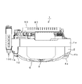
[パチンコシステムの外観構成]
次に、パチンコシステムの外観構成について図を参照して説明する。図2は、図1に示すパチンコシステムの外観を示す正面斜視図であり、図3は、図2に示すパチンコシステムの平面図である。図4は、図2に示すパチンコ機に設けられた貸出ボタンなどを示す説明図である。
[Appearance structure of pachinko system]
Next, the external configuration of the pachinko system will be described with reference to the drawings. FIG. 2 is a front perspective view showing the appearance of the pachinko system shown in FIG. 1, and FIG. 3 is a plan view of the pachinko system shown in FIG. FIG. 4 is an explanatory diagram showing a lending button and the like provided on the pachinko machine shown in FIG.
パチンコ機1の左側にはプリペイド記録媒体読取装置100が設けられている。パチンコ機1には、外殻を構成する外枠セット8が設けられており、この外枠セット8の前面には前枠セット2が設けられている。その前枠セット2は天板1aを備えており、その天板1aの左端前方には回動軸部材1bが設けられている。前枠セット2には透明なガラス枠セット3が、回動軸部材1bを回動軸にして開閉可能に取付けられている。
A prepaid
ガラス枠セット3の内側には、遊技盤(図5において符号5で示す)が設けられており、前枠セット2の前面右下方には、遊技盤5へ遊技球を発射する発射装置を操作する発射ハンドル4aが取付けられている。発射ハンドル4aには、遊技球の発射強度を調節するための発射レバー4bが発射ハンドル4aに対して回動自在に装着されている。
A game board (indicated by
遊技盤5の下方には、パチンコ機1の内部から払出された賞球や貸球を貯留する上受け皿6が設けられている。上受け皿6には、貸球の払出しを行わせるために操作する貸出ボタン6cと、プリペイド記録媒体読取装置100のカード挿入口108から挿入され、装置内部に装填されているプリペイド記録媒体をカード挿入口108から返却させるために操作する返却ボタン6dと、プリペイド記録媒体に記録されている残り度数(残高)を表示する度数表示部6eとが設けられている。度数表示部6eは、残り度数を8セグLEDや液晶を使って数字で表示する。たとえば、度数表示部6eは、残り度数を3桁の数字で表示するように構成されており、たとえば、度数の最小表示単位が100円である場合に500円分が残っているときには、005と表示する。
Below the
上受け皿6の下方には、上受け皿6の貯留可能数を超えて内部から流下した遊技球を貯留する下受け皿7が設けられている。下受け皿7には、下受け皿7に貯留されている遊技球を下受け皿7の下方に配置された賞球箱へ排出するために操作する球抜きレバー7aが設けられている。上受け皿6には、上受け皿6に貯留されている遊技球を下受け皿7へ排出させるために操作する球抜きレバー6aが設けられている。
Below the
前枠セット2には、払出すべき遊技球が無いことを報知する球切れLED13と、遊技球の払出しの異常を報知する払出異常LED14とが設けられている。また、前枠セット2には、効果音を発生する右スピーカ10と、左スピーカ11と、下スピーカ12とが設けられている。また、上受け皿6には、遊技者が演出内容を選択するために操作する演出ボタン9が設けられている。
The front frame set 2 is provided with a
図3に示すように、パチンコ機1の背面上方には、遊技球を貯留するための球タンク80が設けられている。パチンコ機1が設置されている島の上方には各パチンコ機に遊技球を供給する遊技球供給流路が配置されており、その遊技球供給経路から遊技球が球タンク80に供給される。また、パチンコ機1の背面には、パチンコ機1における遊技を制御するための各種の制御基板(図10,図11)が設けられており、それらは、カバー90によって覆われている。
As shown in FIG. 3, a
[遊技盤の主要構成]
次に、パチンコ機1に備えられた遊技盤の主要構成について図を参照して説明する。
図5は図2に示すパチンコ機に備えられた遊技盤の正面図であり、図6は図5に示す遊技盤の正面斜視図である。図7(a)は図5に示す遊技盤に設けられた第1および第2変動入賞装置の正面拡大図、(b)は特別図柄表示装置、普通図柄表示装置、特別図柄記憶表示装置および普通図柄記憶表示装置の正面拡大図である。
[Main components of the game board]
Next, the main configuration of the game board provided in the
5 is a front view of the game board provided in the pachinko machine shown in FIG. 2, and FIG. 6 is a front perspective view of the game board shown in FIG. FIG. 7A is an enlarged front view of the first and second variable winning devices provided on the game board shown in FIG. 5, and FIG. 7B is a special symbol display device, a normal symbol display device, a special symbol memory display device, and a normal symbol display device. It is a front enlarged view of a symbol memory display device.
遊技盤5の盤面には、遊技球が流下する遊技領域が形成されており、遊技球の流下経路は、遊技盤5の盤面に打ち込まれた多数の遊技釘28によって規制されている。遊技盤5の盤面の周囲には、発射ソレノイド(図10において符号4fで示す)などの発射装置によって発射された遊技球を遊技領域に案内するためのレールセット15が設けられている。
A game area where game balls flow down is formed on the board surface of the
遊技盤5の中央には、センター飾り16が設けられている。このセンター飾り16は、図6に示すように盤面から前方へ突出する立体形状に形成されており、遊技領域の中央領域を占有している。センター飾り16には、演出図柄を変動表示したり、各種の演出画像を表示する演出表示器30が設けられている。この実施形態では、演出表示器30は、液晶表示装置により構成されている。なお、LEDをドットマトリクス状に配置した表示器、7セグメントLED、有機ELパネルなどを演出表示器30として用いることもできる。
A
センター飾り16の左外面には、遊技球がセンター飾り16の内部に流入可能な流入口16bが開口形成されている。図6に示すように、センター飾り16の内部には、流入口16bから流入した遊技球を案内するための案内通路16eが設けられている。センター飾り16の左内面には、案内通路16eによって案内された遊技球を流出させるための流出口16cが開口形成されている。
On the left outer surface of the
センター飾り16の下部には、流出口16cから流出した遊技球が転動するためのステージ16dが設けられている。流出口16cから流出した遊技球は、ステージ16dの上を流下経路R2にて流下し、流下経路R3〜R5のいずれかに沿って流下する。ステージ16dの直下であって、流下経路R3に沿った箇所には、第1始動口21が設けられている。ステージ16dの上方には、流出口16cから流出した遊技球以外の遊技球がステージ16dに落下しないようにするための防護部材16fが設けられている。センター飾り16の上面には、案内部16aが形成されており、案内部16aに乗った遊技球は、流下経路R1に沿って、センター飾り16の右方に形成された右寄り遊技領域へ案内される。
A
盤面の左側には、レールセット15の内周に沿って左サイド飾り36が設けられている。左サイド飾り36とセンター飾り16との間には、遊技球が流下する左寄り遊技領域が形成されている。その左寄り遊技領域には、遊技球の流下経路を変化させる風車35が回転自在に設けられている。
On the left side of the board surface, a
左サイド飾り36には、左袖上入賞口17と、左袖入賞口18と、左下入賞口19とが設けられている。盤面の右側には、右サイド飾り37が設けられており、その右サイド飾り37には、右肩入賞口20が設けられている。右寄り遊技領域のセンター飾り16には、普通電動役物27が設けられている。普通電動役物27は、翼形状の開閉翼片27cを備えている。開閉翼片27cは、その基部が回動可能に軸支されており、その基部の回動によって先端を外方(図中では右方)へ開いたり内方(図中では左方)へ閉じたりする。
The
開閉翼片27cが外方へ開くと、その開いた開閉翼片27cとセンター飾り16との間に第2始動口22が形成される。図5は、開閉翼片27cが外方へ開き、第2始動口22が形成された状態を示す。遊技盤5の下方には、どこにも入賞などしなかった遊技球を回収するためのアウト口26が開口形成されている。
When the opening / closing blade piece 27c is opened outward, the
演出表示器30の上方であってセンター飾り16の中央には、LEDによって装飾された可動役物40が設けられている。可動役物40の両端は、支持部材によって支持されており所定の演出タイミングになると演出表示器30の前面に自然落下し、モータ(図11において右リフトモータ40dおよび左リフトモータ40fで示す)などの昇降装置によって上昇して落下前の原点に復帰する。
A
また、可動役物40は、モータ(図11において家紋モータ40bで示す)およびカム機構(図示せず)などの駆動装置によって振動する。可動役物40の背面には、LEDによって装飾された可動役物が設けられており、モータ(図11において万華鏡モータ43aで示す)などの駆動装置によって回転し、可動役物40が落下すると出現する。また、センター飾り16の両側には、可動役物41,42が設けられている。可動役物41,42は、それぞれモータ(図11において左竜モータ41aおよび右竜モータ42aで示す)などの駆動装置によって作動する。
The
また、図6に示すように、センター飾り16の下部であって、演出表示器30の前面下部には、箱状の収納部材46が設けられている。この収納部材46の内部には、左右で一対の可動役物が収納されており、それぞれモータ(図11において扉左モータ44aおよび扉右モータ45aで示す)などの駆動装置によって左右方向へ移動し、それらの可動役物は、合体したときに一つの意匠を構成する。
As shown in FIG. 6, a box-shaped
収納部材46の正面および背面は、透光性材料によって形成されており、遊技者がその内部に収納された可動役物の状態を視認できるようになっている。また、収納部材46の内部において相互に離反した可動役物間に形成された空間の奥には、LEDにより装飾された装飾部材(図示省略)が設けられており、可動役物が相互に離反したときに装飾部材の各LEDが点灯または点滅するようになっている。
The front surface and the back surface of the
この実施形態では、可動役物40は、家紋を模した形状に形成されており、可動役物40を装飾しているLEDが点灯することによって家紋が浮き出るように構成されている。また、可動役物40の背面から出現する可動役物は万華鏡を模した形状に形成されており、その可動役物を装飾しているLEDが点灯または点滅することにより、あたかも万華鏡を覗いているように見える演出を行う。また、可動役物41,42は、それぞれ竜の頭を模した形状に形成されており、前述した駆動装置によって竜が口を開閉する。
In this embodiment, the
また、可動役物41,42の内部には、それぞれLEDが設けられており、そのLEDが点灯することにより、あたかも竜が火を吹くように見える演出を行う。また、収納部材46の内部に収納されている左右で一対の可動役物は、それぞれ扉形状に形成されており、各前面には竜の一部がそれぞれ描かれている。そして、各可動役物が合体すると、竜が完成するようになっている。
Moreover, LED is provided in the inside of the
上述した各可動役物40〜45は、遊技中の所定のタイミングで動作して演出効果を高める。また、各可動役物40〜45は、動作することにより、大当りの発生の予告、大当りの発生の示唆、演出表示器30が大当り発生の確率が高い演出画像を表示することの予告など、各種の予告を行う。
Each movable accessory 40-45 mentioned above operate | moves at the predetermined timing during a game, and raises a production effect. In addition, each
図5において第1始動口21と右肩入賞口20との間(図中において符号Bで示す破線で囲まれた領域)には、図7(a)に示すように、第1変動入賞装置24および第2変動入賞装置25が上下に重ねて設けられている。第1変動入賞装置24は、横長板状の第1開閉部材24dを備えており、この第1開閉部材24dは、ソレノイド(図10において第1大入賞口ソレノイド24bで示す)などの駆動装置によって開閉する。第1開閉部材24dが開放すると、第1大入賞口24aが開口する。
As shown in FIG. 7 (a), the first variable winning device is located between the
第2変動入賞装置25は、横長板状の第2開閉部材25dを備えており、この第2開閉部材25dは、ソレノイド(図10において第2大入賞口ソレノイド25bで示す)などの駆動装置によって開閉する。第2開閉部材25dが開放すると、第2大入賞口25aが開口する。図7(a)は、第1大入賞口24aおよび第2大入賞口25aがそれぞれ開口した状態を示す。第1大入賞口24aおよび第2大入賞口25aは、大当りが発生したときに開口する。この実施形態では、第1開閉部材24dおよび第2開閉部材25dは、それぞれ横長の板状に形成されており、両側の下端を軸にして前後に開閉するように構成されている。
The second variable winning
図5において左サイド飾り36の左袖上入賞口17の左側(図中において符号Aで示す破線で囲まれた領域)には、図7(b)に示すように、特別図柄表示装置31と、普通図柄表示装置33と、特別図柄保留数表示装置32および普通図柄保留数表示装置34とが設けられている。
この実施形態では、特別図柄表示装置31、普通図柄表示装置33、特別図柄保留数表示装置32および普通図柄保留数表示装置34は、それぞれLEDにより構成されているが、液晶表示装置などにより構成することもできる。
As shown in FIG. 7B, a special
In this embodiment, the special
特別図柄表示装置31は複数(たとえば、図7(b)に示すように7個)のLEDにより構成されており、それらのLEDは、遊技球が第1始動口21または第2始動口22に入賞すると所定の点滅パターンで点滅する。それらのLEDが点灯したときの発光色および消灯したときのLEDの地の色が特別図柄を構成し、LEDが点滅している状態が、特別図柄が変動表示している状態である。
The special
特別図柄表示装置31は、各LEDをランダムに点滅させ、その点滅が停止したときに点灯しているLEDおよび消灯しているLEDの組合せが特定の組合せであるときに大当りが発生し、その組合せの種類によって大当りの種類が異なる。大当りの種類は、大当り遊技において実行可能な最大ラウンド数、通常大当り、確変大当りおよび時短のうちの2つ以上を組み合わせて構成されている。また、大当りの種類によって第1変動入賞装置24および第2変動入賞装置25のどちらかが動作して大当り遊技が行われる。
ここで、時短とは、特別図柄が変動表示を開始してから変動表示を終了するまでに要する時間が短縮され、かつ、普通図柄が変動表示を開始してから変動表示を終了するまでに要する時間が短縮された遊技状態をいう。
The special
Here, “short time” means that the time required from the start of the special symbol to the end of the variable display after the special symbol is started is shortened, and that the normal symbol starts from the start of the variable display to the end of the variable display. A game state with reduced time.
特別図柄表示装置31が特別図柄を変動表示しているときに遊技球が始動口21または始動口22に入賞したときは、その入賞に基づく特別図柄の変動表示は直ぐに実行されず、一旦保留される。その保留数は、特別図柄保留数表示装置32によって表示される。この実施形態では、特別図柄保留数表示装置32は4個のLEDによって構成されており、そのLEDの点灯数によって特別図柄保留数を表示する。つまり、この実施形態では、特別図柄保留数は最大4個である。
When the special
演出表示器30は、特別図柄表示装置31の演出効果を高める目的で設けられている。つまり、特別図柄表示装置31は、複数のLEDによって構成されており、LEDの点滅のみでは演出効果が乏しいため、演出表示器30が演出図柄を変動表示したり、演出用の動画などの演出画像を表示したりすることによって演出効果を高めている。なお、演出図柄とは、LEDによって表示される特別図柄に代わって表示する演出用の図柄のことであり、複数の識別情報を表現した図柄である。たとえば、0〜9の数字を表現した図柄であり、演出表示器30は、図柄列を数字の昇順に表示する。また、演出表示器30は、動画および静止画像により構成された演出画像を単独で、あるいは、演出図柄と共に表示する。
The
演出表示器30は、特別図柄表示装置31が特別図柄の変動表示を開始すると同時に演出画像および演出図柄の表示を開始する。また、演出表示器30は、特別図柄表示装置31が特別図柄の変動表示を終了すると同時に演出画像および演出図柄の表示を終了し、特別図柄表示装置31が確定表示した大当り図柄またはハズレ図柄に対応する演出図柄を確定表示する。
The
普通図柄表示装置33は、複数(たとえば、図7(b)に示すように2個)のLEDにより構成されており、各LEDが点灯したときの発光色および消灯したときのLEDの地の色が普通図柄を構成する。また、普通図柄表示装置33がLEDを点滅させている状態が、普通図柄が変動表示している状態であり、変動表示が終了したときに点灯および消灯しているLEDの組合せによって普通図柄の当りまたはハズレが報知される。当りの普通図柄が確定表示されると、普通電動役物27の開閉翼片27cの開放時間が長くなり、普通電動役物27への入賞が容易になる。つまり、単位時間当りに特別図柄が変動表示を開始する回数が多くなり、大当りが発生する確率が高くなる。
The normal
遊技球がゲート23を通過すると、普通図柄表示装置33が普通図柄の変動表示を開始する。そして、普通図柄表示装置33が普通図柄を変動表示しているときに遊技球がゲート23を通過したときは、その通過による普通図柄の変動表示が保留され、その保留数は普通図柄保留数表示装置34により表示される。この実施形態では、普通図柄保留数表示装置34は、4個のLEDによって構成されており、そのLEDの点灯数によって保留数を表示する。つまり、この実施形態では、普通図柄保留数は最大4個である。
When the game ball passes through the
[プリペイド記録媒体読取装置の主要構造]
次に、プリペイド記録媒体読取装置100の主要構造について図を参照して説明する。図8は、図2に示すプリペイド記録媒体読取装置100の外観を示す正面図である。なお、プリペイド記録媒体としては、プリペイドカード、または、コイン形状のプリペイドコインなどが存在するが、この実施形態では、プリペイド記録媒体としてプリペイドカードを使うプリペイド記録媒体読取装置を例に挙げて説明する。
[Main structure of prepaid recording medium reader]
Next, the main structure of the prepaid recording
図8に示すように、プリペイド記録媒体読取装置100には、プリペイドカードの利用が可能であることを示す利用ランプ101と、貸出金額の単位(たとえば、100円、200円、300円、500円)の選択を行うための金額設定ボタン102と、金額設定ボタン102により選択した貸出金額を表示する貸出金額表示部103と、100円未満の残高およびメンテナンス情報を度数表示部6e(図4)に表示させる場合に押す端数表示ボタン104と、プリペイド記録媒体読取装置100が接続されるパチンコ機1の方向を示す連結台方向表示ランプ105とが設けられている。
As shown in FIG. 8, the prepaid
また、プリペイド記録媒体読取装置100には、プリペイドカードがパチンコ機1に対応していることを示す表示ランプ106と、プリペイドカードを挿入するカード挿入口108と、カード挿入口108にプリペイドカードが挿入されていることを示すカード挿入中ランプ107とが設けられている。プリペイド記録媒体読取装置100の内部には、カード挿入口108から挿入されたプリペイドカードを装填する装填装置(図9において符号113で示す)が設けられている。
さらに、プリペイド記録媒体読取装置100には、プリペイド記録媒体読取装置100がパチンコ機1から受信した球貸完了信号EXSのデューティ比が規定値の範囲ではない場合、つまり、球貸完了信号EXSに対して不正行為が行われていることを報知するための報知ランプ130が設けられている。
Further, in the prepaid recording
Further, the prepaid recording
カード挿入口108から挿入されたプリペイドカードは、その端部がカード挿入口108から突出しない状態で上記の装填装置113に装填されるため、装填装置113が故障すると、プリペイドカードを返却することができなくなる。そこで、装填装置113は、カード挿入口108を含む前面パネルの一部と共に前面に引き出し可能に構成されている。装填装置113は、普段はロック機構によって引き出し不能になっているが、プリペイド記録媒体読取装置100に設けられた鍵穴109から鍵を差し込んでロック状態を解除することができるように構成されている。
Since the prepaid card inserted from the
[プリペイド記録媒体読取装置の主な電気的構成]
次に、プリペイド記録媒体読取装置100の主な電気的構成について、それをブロックで示す図9を参照して説明する。
[Main Electrical Configuration of Prepaid Recording Medium Reading Device]
Next, the main electrical configuration of the prepaid
プリペイド記録媒体読取装置100は、カード挿入口108から挿入されたプリペイドカード200を装填して保持するための装填装置113と、その装填装置113に装填されたプリペイドカード200に記録された残り度数を読取る読取装置110と、返却ボタン6d(図4)が操作されたときに装填装置113に装填されているプリペイドカード200をカード挿入口108から返却するための返却装置114とを備える。
The prepaid
また、プリペイド記録媒体読取装置100は、利用ランプ101、貸出金額表示部103、連結台方向表示ランプ105およびカード挿入中ランプ107を点灯または点滅させるための表示装置112と、報知ランプ130を点灯または点滅させるための報知装置111と、MPU(マイクロプロセッサーユニット)120とを備える。MPU120は、CPU121と、ROM122と、RAM123とを備える。
In addition, the prepaid recording
さらに、プリペイド記録媒体読取装置100は、払出要求信号BRQなどをパチンコ機1へ送信する送信回路141と、パチンコ機1から送信される球貸完了信号EXSなどを受信する受信回路142とを備える。
Furthermore, the prepaid recording
CPU121は、パチンコ機1から送信され、受信回路142により受信された球貸完了信号EXSの1周期においてハイレベルになっている時間taおよびローレベルになっている時間tbのデューティ比(tb/ta)を演算する。この実施形態では、CPU121は、自身の動作用クロック信号を用い、球貸完了信号EXSが1周期においてハイレベルに変化している時間taおよびローレベルに変化している時間を計測し、デューティ比(tb/ta)を演算する。
The
そして、その演算したデューティ比が、規定値の範囲であるか否かを判定し、規定値の範囲であると判定した場合は、残り度数を減算し、規定値の範囲ではないと判定した場合は、報知装置111を作動させて報知ランプ130を点灯または点滅させる。つまり、球貸完了信号EXSに対して不正行為が行われていることを報知する。
なお、球貸完了信号EXSが外来ノイズなどの影響を受けてデューティ比が変動することを考慮し、上記の規定値には幅を持たせてあり、デューティ比および規定値の差が極めて小さいにも拘わらず残高が減算されなかったり、報知ランプ130が作動してしまうという事態が起きないようにしている。
Then, it is determined whether the calculated duty ratio is within the specified value range. If it is determined that the calculated duty ratio is within the specified value range, the remaining frequency is subtracted and it is determined that the calculated duty ratio is not within the specified value range. Operates the
In addition, considering that the duty ratio fluctuates due to the influence of external noise or the like on the ball lending completion signal EXS, the above specified value is given a width, and the difference between the duty ratio and the specified value is extremely small. Nevertheless, a situation in which the balance is not subtracted or the
また、CPU121は、装填装置113、返却装置114、読取装置110、報知装置111、表示装置112、送信回路141および受信回路142の動作を制御する。ROM122には、パチンコ機1と通信を行うためにCPU121が実行する通信制御プログラム、さらには、各装置を制御するためにCPU121が実行する各種の制御プログラムなどが読出し可能に格納されている。RAM123は、ROM122から読出された制御プログラムをCPU121が実行するときに使うワーク領域を有するとともに、CPU121の処理結果を書換え可能に格納する。
Further, the
[パチンコ機の主な電気的構成]
次に、パチンコ機1の主な電気的構成についてそれをブロックで示す図10および図11を参照して説明する。
[Main electrical configuration of pachinko machine]
Next, the main electrical configuration of the
図10に示すように、主制御基板50には、主制御用MPU(マイクロプロセッサーユニット)51が搭載されている。主制御用MPU51はICチップであり、主制御基板50の基板面に取付けられた半導体ソケットに対して着脱可能に接続されている。主制御用MPU51は、主制御用CPU52と、主制御用ROM53と、主制御用RAM54とを備える。主制御用CPU52は、大当り判定、主制御用MPU51の識別情報の送信、大当り図柄の抽選、大当りの種類の抽選、ハズレ図柄の抽選、特別図柄変動時間(演出図柄変動時間)の抽選、入賞の検出、ゲート通過の検出、普通図柄の当り判定、賞球の払出命令など、遊技における重要な処理を実行する。
As shown in FIG. 10, a main control MPU (microprocessor unit) 51 is mounted on the
主制御用ROM53には、主制御用CPU52が上記の各処理を実行するためのコンピュータプログラム、各制御基板へ送信する制御コマンド、大当り判定を行う際に参照する大当り値などが読出し可能に格納されている。また、主制御用ROM53には、このパチンコ機1の主制御用MPU51を他のパチンコ機の主制御用MPUと識別するための識別情報が記憶されている。主制御用RAM54は、主制御用CPU52が上記のコンピュータプログラムを実行するときに使用するワーク領域を有する。また、主制御用RAM54は、主制御用CPU52が上記のコンピュータプログラムを実行することにより発生する処理結果および判定結果などを読出しおよび書換え可能に格納する。
The main control ROM 53 stores a computer program for the
また、主制御基板50には、第1始動口21に入賞した遊技球を検出する第1始動口スイッチ21aと、第2始動口22に入賞した遊技球を検出する第2始動口スイッチ22aとが電気的に接続されている。また、主制御基板50には、図柄表示基板84が電気的に接続されている。図柄表示基板84には、特別図柄表示装置31と、特別図柄保留数表示装置32と、普通図柄表示装置33と、普通図柄保留数表示装置34とが搭載されている。また、主制御基板50には、払出制御基板60と、外部端子板85と、セキュリティ中継端子板89とが電気的に接続されている。
The
セキュリティ中継端子板89には、不正行為において使用される誘導磁界を検出するための誘導磁界センサ91と、不正行為において使用される磁気を検出するための第1磁気センサ92と、第2磁気センサ93とが電気的に接続されている。 The security relay terminal plate 89 includes an induced magnetic field sensor 91 for detecting an induced magnetic field used in an illegal act, a first magnetic sensor 92 for detecting magnetism used in an illegal act, and a second magnetic sensor. 93 is electrically connected.
払出制御基板60には、下受け皿7が遊技球で満杯になった状態を検出するための下皿満杯スイッチ7bと、扉開放中継端子板86とが電気的に接続されている。扉中継端子板86には、ガラス枠セット3が開放された状態を検出するための扉開放スイッチ87と、外枠セット8が開放された状態を検出するための外枠開放スイッチ88とが電気的に接続されている。また、払出制御基板60には、払出中継端子板83が電気的に接続されており、払出中継端子板83には、遊技球を上受け皿6へ払出す部材を駆動するための払出モータ38cと、この払出モータ38cによって払出された遊技球を検出するための前部払出センサ38a,後部払出センサ38bと、払出モータ38cによって払出す遊技球が切れていることを検出する前部球切れスイッチ38d,後部球切れスイッチ38eとが電気的に接続されている。
The
払出制御基板60には、払出制御用MPU61が搭載されており、その払出制御用MPU61は、払出制御用CPU62と、払出制御用ROM63と、払出制御用RAM64とを備える。払出制御用CPU62は、主制御用MPU51から送信される払出制御コマンドに従って払出モータ38cを制御し、賞球の払出しを制御する。また、払出制御用CPU62は、前部払出センサ38aおよび後部払出センサ38bからそれぞれ出力される信号の変化を検出し、払出された賞球数を計数する。
The
払出制御用ROM63には、払出制御用CPU62が実行するコンピュータプログラムなどが読出し可能に格納されている。払出制御用RAM64は、払出制御用CPU62が上記のコンピュータプログラムを実行するときに使用するワーク領域を有する。また、払出制御用RAM64は、払出制御用CPU62が上記のコンピュータプログラムを実行することにより発生する処理結果および判定結果などを読出しおよび書換え可能に格納する。また、払出制御基板60には、プリペイドカード200の残り度数を度数表示部6eに表示するための度数表示基板97が接続端子板96を介して電気的に接続されている。
The
さらに、発射制御基板4には、遊技球を発射する発射装置を駆動する発射ソレノイド4fと、遊技球を発射位置へ供給する球供給装置を駆動する球送りソレノイド4gと、発射レバー4bの回動量に応じて発射装置4の発射強度を調節するための発射強度電子ボリューム4cと、遊技者が発射レバー4bに触れたことを検出して発射装置4を駆動させるためのタッチスイッチ4dと、発射レバー4bの回動によってオンまたはオフし、発射ソレノイド4fを駆動する発射スイッチ4eとが電気的に接続されている。
Further, the
主制御基板50には、盤面中継端子板37が電気的に接続されており、その盤面中継端子板37には、左袖上入賞口17に入賞した遊技球を検出するための左袖上入賞口スイッチ17aと、左袖入賞口18に入賞した遊技球を検出するための左袖入賞口スイッチ18aと、左下入賞口19に入賞した遊技球を検出するための左下入賞口スイッチ19aと、右肩入賞口20に入賞した遊技球を検出するための右肩入賞口スイッチ20aと、第1大入賞口24aに入賞した遊技球を検出するための第1大入賞口スイッチ24cと、ゲート23を通過した遊技球を検出するためのゲートスイッチ23aと、第2大入賞口25aに入賞した遊技球を検出するための第2大入賞口スイッチ25cと、第1変動入賞装置24を駆動するための第1大入賞口ソレノイド24bと、普通電動役物27を駆動するための普通電動役物ソレノイド27bと、第2変動入賞装置25を駆動するための第2大入賞口ソレノイド25bとが電気的に接続されている。
A board surface
また、パチンコ機1には、主電源(AC/24V)95に接続された電源基板94が備えられており、電源基板94は、主電源95から供給される電源を主制御基板50と、払出制御基板60と、接続端子板96とに供給する。
The
図11に示すように、パチンコ機1には、演出制御基板400が設けられており、その演出制御基板400には、画像音声制御基板70と、盤面演出中継端子板82と、盤面LED中継端子板81と、補助演出駆動基板410と、演出電源基板94aとが電気的に接続されている。演出制御基板400には、演出制御用CPU402を備えた演出制御用MPU401が搭載されている。演出制御用CPU402は、主制御基板50(図10)から送信された演出制御信号を受信し、その受信した演出制御信号を対応する基板に振り分ける処理などを行う。
As shown in FIG. 11, the
画像音声制御基板70には、液晶中継端子板30aを介して演出表示器30が電気的に接続されている。また、画像音声制御基板70には、盤面演出中継端子板82が電気的に接続されており、その盤面中継端子板82には、枠部演出中継端子板83を介して右スピーカ10と、左スピーカ11と、下スピーカ12とが電気的に接続されている。また、枠部演出中継端子板83には、枠部LED駆動基板66を介して照光付演出スイッチ9aが電気的に接続されている。照光付演出スイッチ9aは、演出ボタン9を押圧操作したときにオンし、演出ボタン9に内蔵されているLEDを点灯させるスイッチである。
The
画像音声制御基板70には、画像音声制御用MPU71が搭載されている。画像音声制御用MPU71は、画像音声制御用CPU72と、画像音声制御用ROM73と、画像音声制御用RAM74とを備える。画像音声制御用CPU72は、主制御基板50から演出制御基板400を介して送信された演出制御信号に従って演出表示器30を制御し、演出制御信号に対応する画像を演出表示器30に表示させる。また、画像音声制御用CPU72は、主制御基板50から演出制御基板400を介して送信された演出制御信号に従って各スピーカ10〜12を駆動し、演出制御信号に対応する効果音を各スピーカ10〜12から出力させる。
An image / audio control MPU 71 is mounted on the image /
画像音声制御用ROM73には、画像音声制御用CPU72が実行するコンピュータプログラムが読出し可能に格納されている。また、画像音声制御用ROM73には、画像音声制御用CPU72がコンピュータプログラムを実行するときに参照する各種のテーブルが読出し可能に格納されている。
また、画像音声制御用ROM73には、特別図柄、普通図柄および演出図柄などの変動パターンを決定するためのテーブルが格納されている。また、画像音声制御用ROM73には、パチンコ機1に設けられた演出用のLEDの点灯パターンを決定するためのテーブル、効果音や音楽の種類を決定するためのテーブルなど、演出に必要なテーブルやデータなどが格納されている。
The image / sound control ROM 73 stores a computer program executed by the image / sound control CPU 72 in a readable manner. The image / sound control ROM 73 stores various tables that can be read when the image / sound control CPU 72 executes the computer program.
Further, the image / sound control ROM 73 stores a table for determining a variation pattern such as a special symbol, a normal symbol, and an effect symbol. Further, the image / sound control ROM 73 includes tables necessary for rendering such as a table for determining the lighting pattern of the LED for rendering provided in the
画像音声制御用RAM74は、画像音声制御用CPU72がコンピュータプログラムを実行するときに使用するワーク領域を有する。また、画像音声制御用RAM74は、画像音声制御用CPU72がコンピュータプログラムを実行することにより発生する処理結果および判定結果などを読出しおよび書換え可能に格納する。 The image / sound control RAM 74 has a work area used when the image / sound control CPU 72 executes a computer program. In addition, the image / sound control RAM 74 stores processing results and determination results generated when the image / sound control CPU 72 executes a computer program in a readable and rewritable manner.
補助演出駆動基板410には、補助演出上中継端子板99と、補助演出右中継端子板68と、補助演出下中継端子板98とが電気的に接続されている。補助演出上中継端子板99には、可動役物40の背面に配置された可動役物を回転させる万華鏡モータ43aと、その可動役物が原点に復帰したことを検出する万華鏡原点センサ43bと、可動役物42を駆動する右竜モータ42aと、可動役物42が原点に復帰したことを検出する右竜原点センサ42bと、可動役物41を駆動する左竜モータ41aと、可動役物41が原点に復帰したことを検出する左竜原点センサ41bとが電気的に接続されている。
The auxiliary effect upper relay terminal plate 99, the auxiliary effect right relay terminal plate 68, and the auxiliary effect lower relay terminal plate 98 are electrically connected to the auxiliary effect drive board 410. The auxiliary terminal relay terminal plate 99 has a kaleidoscope motor 43a for rotating the movable accessory arranged on the back of the
補助演出右中継端子板68には、可動役物40を振動させる家紋モータ40bと、可動役物40bの位置を検出する家紋位置確認センサ40cと、可動役物40を上昇させる右リフト(図示省略)を駆動する右リフトモータ40dと、右リフトが原点に復帰したことを検出する右リフト原点センサ40eとが電気的に接続されている。
補助演出下中継端子板98には、可動役物40を上昇させる左リフト(図示省略)を駆動する左リフトモータ40fと、左リフトが原点に復帰したことを検出する左リフト原点センサ40gと、収納部材46の内部右側に配置された可動役物を移動させる扉右モータ45aと、その可動役物が原点に復帰したことを検出する扉右原点センサ45bと、収納部材46の内部左側に配置された可動役物を移動させる扉左モータ44aと、その可動役物が原点に復帰したことを検出する扉左原点センサ44bとが電気的に接続されている。
The auxiliary effect right relay terminal board 68 has a family crest motor 40b that vibrates the
The auxiliary effect lower relay terminal board 98 includes a left lift motor 40f that drives a left lift (not shown) that raises the
補助演出駆動基板410には、補助演出制御用MPU420が搭載されている。補助演出制御用MPU420は、補助演出制御用CPU421と、補助演出制御用ROM422と、補助演出制御用RAM423とを備える。補助演出制御用CPU421は、主制御基板50から演出制御基板400を介して送信された演出制御信号に従って各可動役物の動作を制御する。補助演出制御用ROM422には、補助演出制御用CPU421が実行するコンピュータプログラムが読出し可能に格納されている。また、補助演出制御用ROM422には、補助演出制御用CPU421がコンピュータプログラムを実行するときに参照する各種のテーブル(たとえば、可動役物の動作パターン)が読出し可能に格納されている。
An auxiliary effect control MPU 420 is mounted on the auxiliary effect drive board 410. The auxiliary effect control MPU 420 includes an auxiliary effect control CPU 421, an auxiliary effect control ROM 422, and an auxiliary effect control RAM 423. The auxiliary effect control CPU 421 controls the operation of each movable accessory according to the effect control signal transmitted from the
補助演出制御用RAM423は、補助演出制御用CPU421がコンピュータプログラムを実行するときに使用するワーク領域を有する。また、補助演出制御用RAM423は、補助演出制御用CPU421がコンピュータプログラムを実行することにより発生する処理結果および判定結果などを読出しおよび書換え可能に格納する。 The auxiliary effect control RAM 423 has a work area used when the auxiliary effect control CPU 421 executes the computer program. Further, the auxiliary effect control RAM 423 stores processing results and determination results generated by the auxiliary effect control CPU 421 executing the computer program in a readable and rewritable manner.
演出電源基板94aは、電源基板94(図10)から供給される電源を演出電源基板94aと電気的に接続された各基板へ分配する。盤面LED中継端子板81には、遊技盤5に設けられた装飾用の各LEDが搭載されている。
The effect power supply board 94a distributes the power supplied from the power supply board 94 (FIG. 10) to each board electrically connected to the effect power supply board 94a. On the board surface LED relay terminal board 81, each LED for decoration provided in the
[貸球の払出しに関係する部分の主な電気的構成]
次に、貸球の払出しに関係する部分の主な電気的構成について、それをブロックで示す図12を参照して説明する。
[Main electrical structure of the part related to paying out rented balls]
Next, the main electrical configuration of the portion related to paying out the rental balls will be described with reference to FIG.
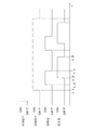
図12に示すように、払出制御基板60には、プリペイド記録媒体読取装置100との間で信号の送受信を行う入出力回路60aと、周辺回路(入力)60bと、周辺回路(出力)60cと、スイッチ入力回路60dと、信号作成回路60kと、MPU61とが実装されている。信号作成回路60kは、1周期においてハイレベルになっている時間およびローレベルになっている時間のデューティ比が特定のデューティ比になっている球貸完了信号EXSを作成する。この実施形態では、球貸完了信号EXSは、ハイレベルの期間がtaでローレベルの期間がtbであり、デューティ比=ローレベルの期間/ハイレベルの期間=tb/taに設定されている(図14)。
As shown in FIG. 12, the
スイッチ入力回路60dは、MPU61および払出中継端子板83と電気的に接続されている。度数表示基板97には、貸出ボタン6cと、返却ボタン6dと、度数表示部6eとが電気的に接続されている。
The
[プリペイド記録媒体読取装置および払出制御基板間の通信]
次に、プリペイド記録媒体読取装置100および払出制御基板60間で行う通信について図を参照して説明する。図13は、プリペイド記録媒体読取装置100および払出制御基板60間の信号の流れを示す説明図であり、図14は、プリペイド記録媒体読取装置100および払出制御基板60間で行う通信のタイミングチャートである。
[Communication between prepaid recording medium reader and payout control board]
Next, communication performed between the prepaid recording
払出制御基板60には、払出制御用CPUバス60eを介して出力ポート60gが接続されており、出力ポート60gはアイソレーション回路60iを介してプリペイド記録媒体読取装置100と接続されている。プリペイド記録媒体読取装置100は、アイソレーション回路60jを介して入力ポート60hと接続されており、入力ポート60hは、払出制御用CPUバス60fを介して払出制御基板60と接続されている。
An
払出制御基板60に搭載されたMPU61から送信された払出可能状態信号PRDYおよび球貸完了信号EXSは、払出制御用CPUバス60eから出力ポート60gを介してアイソレーション回路60iを通り、プリペイド記録媒体読取装置100に搭載されたMPU120によって受信される。また、プリペイド記録媒体読取装置100に搭載されたMPU120から送信された払出要求信号BRQおよび球貸処理中信号BRDYは、アイソレーション回路60jを通り、入力ポート60hからを介してMPU61によって受信される。
The payable state signal PRDY and the ball lending completion signal EXS transmitted from the
MPU120を構成するCPU121は、パチンコ機1から受信した球貸完了信号EXSの1周期においてハイレベルに変化している時間taおよびローレベルに変化している時間tbを計測し、デューティ比(tb/ta)が規定値の範囲であると判定した場合は残り度数を減算し、規定値の範囲ではないと判定した場合は、報知ランプ130を点灯または点滅させ、球貸完了信号EXSに対して不正行為が行われていることを報知する。
The
したがって、球貸完了信号EXSが流れる通信ケーブルに不正基板を接続し、球貸完了信号EXSを強制的にハイレベルに変化させて残り度数が減算されないようにする不正行為を行うと、報知ランプ130が点灯または点滅するため、不正行為を容易に発見することができる。
Accordingly, when an unauthorized board is connected to the communication cable through which the ball lending completion signal EXS flows and the ball lending completion signal EXS is forcibly changed to a high level to prevent the remaining frequency from being subtracted, the
プリペイド記録媒体読取装置100のMPU120を構成するCPU121は、払出制御基板60から送信される球貸完了信号EXSを受信し、その受信した球貸完了信号EXSのデューティ比が規定値の範囲である場合は残り度数を減算する。たとえば、最初にプリペイドカード200から読取った残り度数が「100」であり、1回の払出しで5度数分払出すように設定されているとすると、球貸完了信号EXSがハイレベルからローレベルに変化したときに残り度数の「100」からを「5」を減算し、残り度数を「95」とする。また、CPU121は、受信した球貸完了信号EXSのデューティ比が規定値の範囲ではない場合は報知ランプ130を点灯または点滅させてエラー報知を行う。
When the
[CPUが球貸しのために実行する処理]
次に、プリペイド記録媒体読取装置100のCPU121および払出制御基板60のCPU61が球貸しのために実行する処理について図を参照して説明する。
図15は、プリペイド記録媒体読取装置100のCPU121が実行する球貸し要求確認処理1の内容を示すフローチャートであり、図16は、払出制御基板60のCPU61が実行する球貸し処理1の流れを示すフローチャートである。なお、以下の説明では、CPUが実行する処理ステップをSと略す。
[Processes executed by the CPU for lending a ball]
Next, processing executed for lending by the
FIG. 15 is a flowchart showing the contents of the ball lending
(球貸し要求確認処理1)
プリペイド記録媒体読取装置100のCPU121は、読取装置110(図9)がプリペイドカード200を既に検出中であるか否かを判定し(S1)、検出中ではないと判定すると(S1:No)、初めてプリペイドカード200を検出したか否かを判定する(S2)。ここで、検出したと判定すると(S2:Yes)、プリペイドカード200に記録されている残り度数R1を読取り、その読取った残り度数R1をRAM123に格納する(S3)。
(Ball lending request confirmation process 1)
The
続いて、貸出ボタン6cがONしたか否かを判定し(S4)、ONしたと判定すると(S4:Yes)、先のS3においてRAM123に格納した残り度数R1が、貸球の払出しを行うために必要な最小度数以上であるか否かを判定する(S5)。ここで、最小度数以上であると判定すると(S5:Yes)、球貸処理中信号BRDYをローレベルからハイレベルに変化させる(S6)。
Subsequently, it is determined whether or not the
続いて、払出要求信号BRQを払出制御基板60へ送信し(S7)、球貸完了信号EXSを受信したか否かを判定する(S8)。ここで、受信したと判定すると(S8:Yes)、その受信した球貸完了信号EXSのデューティ比を演算し(S9)、その演算したデューティ比が規定値の範囲か否かを判定する(S10)。ここで、規定値の範囲であると判定した場合は(S10:Yes)、先のS3において読取った残り度数を減算する(S11)。たとえば、貸出ボタン6cが1回ONしたときに5度数分の貸球が払出されるように設定されている場合は、残り度数R1から5度数分を減算する。
Subsequently, a payout request signal BRQ is transmitted to the payout control board 60 (S7), and it is determined whether or not the ball lending completion signal EXS is received (S8). Here, if it is determined that it has been received (S8: Yes), the duty ratio of the received ball rental completion signal EXS is calculated (S9), and it is determined whether or not the calculated duty ratio is within a specified value range (S10). ). If it is determined that the value is within the specified value range (S10: Yes), the remaining frequency read in the previous S3 is subtracted (S11). For example, when the
また、S10において規定値の範囲ではないと判定した場合は(S10:No)、報知ランプ130を点灯または点滅させてエラー報知を行う(S12)。また、先のS2において、プリペイドカード200を検出中ではないと判定した場合は(S2:No)、球貸処理中信号BRDYをローレベルに戻す(S13)。
If it is determined in S10 that the value is not within the specified value range (S10: No), the
(球貸し処理1)
払出制御基板60のCPU61は、球貸処理中信号BRDYがハイレベルであるか否かを判定し(図16のS30)、ハイレベルであると判定すると(S30:Yes)、プリペイド記録媒体読取装置100のCPU121がS7(図15)において送信した払出要求信号BRQを受信したか否かを判定する(S31)。ここで、払出要求信号BRQを受信したと判定すると(S31:Yes)、払出モータ38c(図10)を駆動して貸球を払出す(S32)。
(Ball rental process 1)
The
続いて、球貸完了信号EXSをハイレベルに変化させ(S33)、貸球の払出数Pのカウントを開始する(S34)。続いて、払出数Pが規定の25個に達したか否かを判定し(S35)、25個に達したと判定すると(S35:Yes)、払出回数Nに1を加算する(S36)。続いて、払出回数Nが規定の5回に達したか否かを判定し(S37)、5回に達したと判定すると(S37:Yes)、特定のデューティ比(tb/ta)を有する球貸完了信号EXSをプリペイド記録媒体読取装置100へ送信する(S38)。 Subsequently, the ball lending completion signal EXS is changed to a high level (S33), and counting of the number of balls to be paid out P is started (S34). Subsequently, it is determined whether or not the number of payouts P has reached the prescribed 25 (S35). If it is determined that the number has reached 25 (S35: Yes), 1 is added to the number of payouts N (S36). Subsequently, it is determined whether or not the number N of payouts has reached the prescribed five times (S37), and if it is determined that the number has reached five (S37: Yes), a ball having a specific duty ratio (tb / ta) A lending completion signal EXS is transmitted to the prepaid recording medium reader 100 (S38).
[第1実施形態の効果]
上述したように、第1実施形態のパチンコシステムを使用すれば、パチンコ機1は、信号の1周期においてハイレベルに変化している時間taおよびローレベルに変化している時間tbのデューティ比(tb/ta)として特定のデューティ比を有する球貸完了信号EXSをプリペイド記録媒体読取装置100へ送信し、プリペイド記録媒体読取装置100は、パチンコ機1から受信した球貸完了信号EXSが上記特定のデューティ比であると判定した場合は残り度数を減算し、特定のデューティ比ではないと判定した場合は報知ランプ130を点灯または点滅させてエラー報知を行うことができる。
[Effect of the first embodiment]
As described above, when the pachinko system according to the first embodiment is used, the
つまり、パチンコ機1がプリペイド記録媒体読取装置100へ送信する球貸完了信号EXSの信号レベルを強制的に変化させる不正行為を行うと、球貸完了信号EXSのデューティ比が特定のデューティ比と異なるデューティ比になるため、エラー報知される。
したがって、球貸完了信号EXSを強制的に変化させることにより、残り度数が減算されないようにする不正行為を容易に発見することができる。
That is, when an illegal act of forcibly changing the signal level of the ball lending completion signal EXS transmitted from the
Therefore, by forcibly changing the ball lending completion signal EXS, it is possible to easily find an illegal act that prevents the remaining frequency from being subtracted.
〈第2実施形態〉
次に、この発明の第2実施形態について図を参照して説明する。
この実施形態に係るパチンコシステムは、球貸完了信号EXSに対する不正行為が行われた場合に貸球の払出しを中止することを特徴とする。なお、この実施形態に係るパチンコシステムは、プリペイド記録媒体読取装置100のCPU121および払出制御基板60のCPU61が実行する内容の一部以外は、前述した第1実施形態のパチンコシステムと同じ構成および機能であるため、この実施形態では、同じ構成については同じ符号を用いるものとし、同じ部分の説明を省略または簡略化して説明する。
Second Embodiment
Next, a second embodiment of the present invention will be described with reference to the drawings.
The pachinko system according to this embodiment is characterized in that when a fraudulent act with respect to the ball lending completion signal EXS is performed, the lending of the ball is stopped. The pachinko system according to this embodiment has the same configuration and functions as the pachinko system according to the first embodiment described above, except for some of the contents executed by the
図17は、プリペイド記録媒体読取装置のCPUが実行する球貸し要求確認処理2の内容を示すフローチャートである。図18は、払出制御基板のCPUが実行する球貸し処理2の内容を示すフローチャートである。
FIG. 17 is a flowchart showing the contents of the ball lending
(球貸し要求確認処理2)
プリペイド記録媒体読取装置100のCPU121は、前述した第1実施形態の球貸し要求確認処理1のS1〜S13(図15)と同じ処理を実行する。そして、エラー報知を行うと(S12)、払出制御基板60へエラー信号を送信する(S14)。
(Lending request confirmation process 2)
The
(球貸し処理2)
払出制御基板60のCPU61は、払出要求信号BRQがハイレベルに変化しているか否かを判定し(S31)、ハイレベルに変化していると判定すると(S31:Yes)、プリペイド記録媒体読取装置100がS14(図17)において送信したエラー信号を受信したか否かを判定する(S31a)。ここで、エラー信号を受信したと判定すると(S31a:Yes)、貸球の払出しを中止する。
(Ball rental process 2)
The
[第2実施形態の効果]
上述したように、第2実施形態のパチンコシステムを使用すれば、プリペイド記録媒体読取装置100がパチンコ機1から送信された球貸完了信号EXSのデューティ比が特定のデューティ比ではないと判定した場合に、パチンコ機1における貸球の払出しを中止させることができる。
したがって、貸球を不正に払出させようとする者が、貸球の払出しを受けて遊技ができないようにすることができる。
[Effects of Second Embodiment]
As described above, when the pachinko system according to the second embodiment is used, the prepaid
Therefore, it is possible to prevent a person who tries to illegally pay out a rental ball from playing the rental ball and cannot play a game.
〈第3実施形態〉
次に、この発明の第3実施形態について図を参照して説明する。
この実施形態に係るパチンコシステムは、球貸完了信号EXSを細工する不正行為が行われているパチンコシステムをホールコンピュータにおいて特定することを特徴とする。なお、この実施形態に係るパチンコシステムは、プリペイド記録媒体読取装置100のCPU121が実行する内容の一部以外は、前述した第1実施形態のパチンコシステムと同じ構成および機能であるため、同じ構成については同じ符号を用いるものとし、同じ部分の説明を省略または簡略化して説明する。図19は、CPU121が実行する球貸し要求確認処理3の内容を示すフローチャートであり、図20は、ホールコンピュータが実行する報知処理の内容を示すフローチャートである。
<Third Embodiment>
Next, a third embodiment of the invention will be described with reference to the drawings.
The pachinko system according to this embodiment is characterized in that the hall computer identifies a pachinko system in which an illegal act of crafting the ball lending completion signal EXS is performed. Note that the pachinko system according to this embodiment has the same configuration and functions as the pachinko system of the first embodiment described above, except for a part of the contents executed by the
プリペイド記録媒体読取装置100のCPU121は、前述した第1実施形態の球貸し要求確認処理1のS1〜S13(図15)と同じ処理を実行する。そして、エラー報知を行うと(S12)、ホールコンピュータ300へエラー信号を送信する(S14)。このエラー信号は、球貸完了信号EXSを細工する不正行為が行われているパチンコシステムをホールコンピュータ300において特定させるための信号であり、不正行為が行われているパチンコシステムを構成するパチンコ機1の台番号が含まれている。
The
一方、ホールコンピュータ300は、プリペイド記録媒体読取装置100から送信されたエラー信号を受信したか否かを判定する(図20のS100)。ここで、エラー信号を受信したと判定した場合は(S100:Yes)、その受信したエラー信号を解析し(S101)、エラー信号に含まれる台番号を抽出する。続いて、その抽出した台番号をホールコンピュータ300に接続された表示装置301(図1)の画面に表示する(S102)。つまり、球貸完了信号EXSを細工する不正行為が行われているパチンコ機1を特定する表示を行う。
On the other hand, the hall computer 300 determines whether or not the error signal transmitted from the prepaid
[第3実施形態の効果]
上述したように、第3実施形態のパチンコシステムを使用すれば、プリペイド記録媒体読取装置100がパチンコ機1から受信した球貸完了信号EXSが特定のデューティ比でない場合は、そのパチンコ機1を特定する表示をホールコンピュータ300の表示装置301によって行うことができる。
したがって、パチンコホールの従業者は、球貸完了信号EXSを細工する不正行為が行われているパチンコ機1および遊技者を容易に特定することができる。
[Effect of the third embodiment]
As described above, if the pachinko system according to the third embodiment is used, if the ball lending completion signal EXS received from the
Therefore, the employee of the pachinko hall can easily specify the
〈第4実施形態〉
次に、この発明の第4実施形態について図を参照して説明する。
この実施形態に係るパチンコシステムは、球貸完了信号EXSを細工する不正行為が行われている場合は、返却ボタンが操作されてもプリペイドカードが返却されないようにすることを特徴とする。なお、この実施形態に係るパチンコシステムは、プリペイド記録媒体読取装置100のCPU121が実行する内容の一部以外は、前述した第1実施形態のパチンコシステムと同じ構成および機能であるため、同じ構成については同じ符号を用いるものとし、同じ部分の説明を省略または簡略化して説明する。図21は、プリペイド記録媒体読取装置のCPUが実行するカード返却処理の内容を示すフローチャートである。
<Fourth embodiment>
Next, a fourth embodiment of the invention will be described with reference to the drawings.
The pachinko system according to this embodiment is characterized in that, when an illegal act of crafting the ball lending completion signal EXS is performed, the prepaid card is not returned even if the return button is operated. Note that the pachinko system according to this embodiment has the same configuration and functions as the pachinko system of the first embodiment described above, except for a part of the contents executed by the
プリペイド記録媒体読取装置100のCPU121は、返却ボタン6d(図4)がONしたか否かを判定し(S50)、ONしたと判定すると(S50:Yes)、エラー報知を行ったか否かを判定する(S51)。ここで、エラー報知を行っていないと判定した場合は(S51:No)、返却装置114(図9)を駆動させてプリペイドカード200をカード挿入口108から返却する(S52)。また、エラー報知を行っていると判定した場合は(S51:Yes)、返却装置114を駆動しないで次の処理へ移行する。つまり、球貸完了信号EXSに細工が施されている場合は、プリペイドカード200をカード挿入口108から返却しないように制御する。
The
[第4実施形態の効果]
上述したように、第4実施形態のパチンコシステムを使用すれば、球貸完了信号EXSを細工する不正行為が行われている場合は、返却ボタン6dが操作された場合であってもカード挿入口108からプリペイドカード200を返却しないようにすることができる。
したがって、同じプリペイドカードを使った不正行為の再発を防止することができる。
[Effect of Fourth Embodiment]
As described above, if the pachinko system according to the fourth embodiment is used, the card insertion slot can be used even when the return button 6d is operated when an illegal act of crafting the ball lending completion signal EXS is performed. It is possible not to return the
Accordingly, it is possible to prevent a relapse of fraud using the same prepaid card.
〈第5実施形態〉
次に、この発明の第5実施形態について図を参照して説明する。
この実施形態に係るパチンコシステムは、球貸完了信号EXSを細工する不正行為が行われている場合に、そのパチンコシステムのパチンコ機によって遊技をしている遊技者の顔を撮影し、その撮影データを格納することを特徴とする。なお、この実施形態に係るパチンコシステムは、プリペイド記録媒体読取装置100の構成およびCPU121が実行する内容の一部以外は、前述した第1実施形態のパチンコシステムと同じ構成および機能であるため、同じ構成については同じ符号を用いるものとし、同じ部分の説明を省略または簡略化して説明する。図22は、プリペイド記録媒体読取装置の外観を示す正面図である。図23は、プリペイド記録媒体読取装置のCPUが実行する撮影処理の内容を示すフローチャートである。
<Fifth Embodiment>
Next, a fifth embodiment of the present invention will be described with reference to the drawings.
The pachinko system according to this embodiment shoots the face of a player playing a game with the pachinko machine of the pachinko system when an illegal act of crafting the ball lending completion signal EXS is performed, and the shooting data Is stored. The pachinko system according to this embodiment has the same configuration and functions as the pachinko system of the first embodiment described above except for the configuration of the prepaid recording
図22に示すように、プリペイド記録媒体読取装置100には、このプリペイド記録媒体読取装置100が接続されたパチンコ機1によって遊技をしている遊技者の顔を撮影するカメラ302が設けられている。また、カメラ302は、撮影した遊技者の顔を示す撮影データを格納する格納媒体303と電気的に接続されている。たとえば、カメラ302は、CMOSセンサを用いたデジタルカメラであり、静止画像および動画像を撮影することができる。また、格納媒体303は、SDカードなどの汎用性を有する格納媒体である。
As shown in FIG. 22, the prepaid
プリペイド記録媒体読取装置100のCPU121は、エラー報知を行ったか否かを判定する(図23のS60)。ここで、エラー報知を行ったと判定すると(S60:Yes)、カメラ302を駆動して遊技者の顔を撮影し(S61)、その撮影データを格納媒体303に格納する(S62)。
The
[第5実施形態の効果]
上述したように、第5実施形態のパチンコシステムを使用すれば、球貸完了信号EXSを細工する不正行為が行われている場合は、そのパチンコ機1において遊技をしている遊技者の顔を撮影し、その撮影データを格納媒体303に格納することができる。
したがって、球貸完了信号EXSを細工する不正行為を行う者を容易に特定することができ、かつ、その者の顔を撮影した撮影データを証拠として保存することができる。
[Effect of Fifth Embodiment]
As described above, when the pachinko system according to the fifth embodiment is used, when an illegal act of crafting the ball lending completion signal EXS is performed, the face of the player who is playing the game in the
Therefore, it is possible to easily identify a person who performs an illegal act of crafting the ball lending completion signal EXS, and it is possible to save photographing data obtained by photographing the person's face as evidence.
〈他の実施形態〉
(1)前述したエラー報知は、プリペイド記録媒体読取装置100およびパチンコ機1のいずれか、あるいは両方で行うことができる。また、パチンコホールにおける島に設置された島ランプを点灯させてエラー報知を行うこともできる。さらに、パチンコ機1に備えられたスピーカ10〜12から警報音を発生させてエラー報知を行うこともできる。さらに、ランプ類の点灯および警報音の発生の両方を行うこともできる。
<Other embodiments>
(1) The error notification described above can be performed by one or both of the prepaid recording
(2)エラー報知を行うと共にパチンコ機1による遊技が続行不能となるように構成することもできる。たとえば、演出表示器30による演出表示を中止し、あるいは、遊技球の発射装置の駆動を停止する。これにより、球貸完了信号EXSに細工を施す不正行為を中止させることができ、かつ、その不正行為が行われているパチンコシステムを容易に発見することができる。
(2) It can also be configured such that an error is notified and a game by the
1・・パチンコ機、4f・・発射ソレノイド(発射装置)、5・・遊技盤、
6・・上受け皿(遊技球貯留部材)、6c・・貸出ボタン(貸球操作部材)、
17・・左袖上入賞口、38c・・払出モータ(遊技球払出装置)、
100・・プリペイド記録媒体読取装置、108・・カード挿入口(挿入口)、
200・・プリペイドカード(プリペイド記録媒体)。
1 .. Pachinko machine, 4f .. Launch solenoid (launch device), 5 .. Game board,
6. ・ Upper tray (game ball storage member), 6c ・ ・ Lending button (ball rental operation member),
17. · Left sleeve upper winning opening, 38c ·· Payout motor (game ball payout device),
100 .. Prepaid recording
200 .. Prepaid card (prepaid recording medium).
Claims (5)
前記パチンコ機は、
盤面上に遊技領域が形成された遊技盤と、
前記遊技盤に設けられた入賞口と、
遊技球を前記遊技領域へ発射する発射装置と、
前記発射装置へ供給する遊技球を貯留する遊技球貯留部材と、
貸球の払出しを行うために遊技者が操作する貸球操作部材と、
前記発射装置により発射された遊技球が前記入賞口に入賞したときに賞球を前記遊技球貯留部材へ払出し、さらに、前記プリペイド記録媒体読取装置から払出要求信号が出力されたときに貸球を所定個数単位で前記遊技球貯留部材へ払出す遊技球払出装置と、を備え、前記遊技球払出装置が前記貸球の払出しを完了したことを示す球貸完了信号を前記プリペイド記録媒体読取装置へ送信するように構成されており、
前記プリペイド記録媒体読取装置は、
プリペイド記録媒体を挿入する挿入口と、
前記挿入口に挿入されたプリペイド記録媒体に記録された残高を読取る残高読取部と、を備えており、前記貸球操作部材が操作されたことを検出した場合に、前記残高読取部により読取られた残高が前記貸球を前記所定個数単位で払出すために必要な最小の残高以上であることを条件として前記遊技球払出装置に前記払出要求信号を出力し、かつ、前記球貸完了信号を受信する毎に、前記残高読取部が読取った残高を減算するように構成されたパチンコシステムにおいて、
前記パチンコ機は、
信号の1周期においてハイレベルに変化している時間およびローレベルに変化している時間のデューティ比として特定のデューティ比を有する球貸完了信号を前記プリペイド記録媒体読取装置へ送信し、
前記プリペイド記録媒体読取装置は、
前記パチンコ機から送信された球貸完了信号を受信し、その受信した球貸完了信号のデューティ比が前記特定のデューティ比であるか否かを判定する判定手段を備えており、前記判定手段が肯定判定した場合は、前記残高読取部が読取った残高を減算し、かつ、前記判定手段が否定判定した場合は、その判定結果を示す報知を行うように構成されていることを特徴とするパチンコシステム。 A pachinko system comprising a pachinko machine and a prepaid recording medium reader disposed between the pachinko machines,
The pachinko machine
A game board in which a game area is formed on the board;
A prize opening provided in the game board;
A launcher that launches a game ball into the game area;
A game ball storage member for storing game balls to be supplied to the launcher;
A lending operation member operated by a player to pay out a lending ball;
When the game ball launched by the launching device wins the winning opening, the prize ball is paid out to the game ball storage member, and when the payout request signal is output from the prepaid recording medium reader, A game ball payout device for paying out to the game ball storage member in units of a predetermined number, and a ball lending completion signal indicating that the game ball payout device has completed paying out the lending ball to the prepaid recording medium reading device. Configured to send,
The prepaid recording medium reader is
An insertion slot for inserting a prepaid recording medium,
A balance reading unit that reads the balance recorded on the prepaid recording medium inserted into the insertion slot, and is read by the balance reading unit when it is detected that the ball operating member has been operated. The payout request signal is output to the gaming ball payout device on condition that the balance is equal to or greater than the minimum balance required for paying out the balls in the predetermined number unit, and the ball lending completion signal is In the pachinko system configured to subtract the balance read by the balance reading unit each time it is received,
The pachinko machine
Transmitting a ball lending completion signal having a specific duty ratio to the prepaid recording medium reader as a duty ratio of a time changing to a high level and a time changing to a low level in one cycle of the signal;
The prepaid recording medium reader is
Receiving a ball lending completion signal transmitted from the pachinko machine, and determining means for determining whether or not the duty ratio of the received ball lending completion signal is the specific duty ratio; When the determination is affirmative, the balance read by the balance reading unit is subtracted, and when the determination means makes a negative determination, the pachinko is configured to perform notification indicating the determination result. system.
前記パチンコ機は、前記判定手段の判定結果を前記ホールコンピュータへ送信し、
前記ホールコンピュータは、前記パチンコ機から送信された判定結果に基づいて、前記判定手段の否定判定の対象となったパチンコ機を特定する表示を前記表示装置に行うように構成されていることを特徴とする請求項1または請求項2に記載のパチンコシステム。 The pachinko hall management room where each pachinko machine is installed is equipped with a hall computer that communicates with each pachinko machine, and a display device that displays the processing results of the hall computer on the screen,
The pachinko machine transmits the determination result of the determination means to the hall computer,
The hall computer is configured to display on the display device the pachinko machine that is the object of negative determination by the determination unit based on the determination result transmitted from the pachinko machine. The pachinko system according to claim 1 or 2.
前記挿入口から挿入された前記プリペイド記録媒体を装置内部に装填するための装填装置と、
前記装填装置により装置内部に装填されたプリペイド記録媒体を前記挿入口から返却する返却装置と、を備えており、
当該パチンコシステムは、
前記返却装置を作動させるために操作する返却操作部材と、
前記判定手段が否定判定した場合は、前記返却操作部材が操作された場合であっても前記返却装置の作動を禁止する返却禁止手段と、を備えることを特徴とする請求項1ないし請求項3のいずれか1つに記載のパチンコシステム。 The prepaid recording medium reader is
A loading device for loading the prepaid recording medium inserted from the insertion port into the device;
A return device for returning the prepaid recording medium loaded inside the device by the loading device from the insertion port,
The pachinko system
A return operation member operated to operate the return device;
4. A return prohibiting unit that prohibits the operation of the return device even when the return operation member is operated when the determination unit makes a negative determination. The pachinko system according to any one of the above.
前記撮影装置により撮影された撮影データを格納する撮影データ格納手段と、を備えており、
前記判定手段が否定判定した場合に前記撮影装置により前記遊技者の顔を撮影し、その撮影した撮影データを前記撮影データ格納手段に格納するように構成されたことを特徴とする請求項1ないし請求項4のいずれか1つに記載のパチンコシステム。 A photographing device for photographing a player's face;
Photographing data storage means for storing photographing data photographed by the photographing device,
2. The apparatus according to claim 1, wherein when said determination means makes a negative determination, said photographing device photographs said player's face and stores the photographed photographing data in said photographing data storage means. The pachinko system according to any one of claims 4.
Priority Applications (1)
| Application Number | Priority Date | Filing Date | Title |
|---|---|---|---|
| JP2011036850A JP5578570B2 (en) | 2011-02-23 | 2011-02-23 | Pachinko machine |
Applications Claiming Priority (1)
| Application Number | Priority Date | Filing Date | Title |
|---|---|---|---|
| JP2011036850A JP5578570B2 (en) | 2011-02-23 | 2011-02-23 | Pachinko machine |
Publications (2)
| Publication Number | Publication Date |
|---|---|
| JP2012170711A JP2012170711A (en) | 2012-09-10 |
| JP5578570B2 true JP5578570B2 (en) | 2014-08-27 |
Family
ID=46974158
Family Applications (1)
| Application Number | Title | Priority Date | Filing Date |
|---|---|---|---|
| JP2011036850A Expired - Fee Related JP5578570B2 (en) | 2011-02-23 | 2011-02-23 | Pachinko machine |
Country Status (1)
| Country | Link |
|---|---|
| JP (1) | JP5578570B2 (en) |
Family Cites Families (1)
| Publication number | Priority date | Publication date | Assignee | Title |
|---|---|---|---|---|
| JP5160004B2 (en) * | 2001-08-13 | 2013-03-13 | 株式会社三共 | Game machine and recording medium processing apparatus |
-
2011
- 2011-02-23 JP JP2011036850A patent/JP5578570B2/en not_active Expired - Fee Related
Also Published As
| Publication number | Publication date |
|---|---|
| JP2012170711A (en) | 2012-09-10 |
Similar Documents
| Publication | Publication Date | Title |
|---|---|---|
| JP7698329B2 (en) | Gaming Machines | |
| JP5615204B2 (en) | Pachinko system | |
| JP7676039B2 (en) | Gaming Machines | |
| JP7698330B2 (en) | Gaming Machines | |
| JP5615206B2 (en) | Pachinko system | |
| JP5578570B2 (en) | Pachinko machine | |
| JP5578569B2 (en) | Pachinko machine | |
| JP5615205B2 (en) | Pachinko system | |
| JP2012176049A (en) | Pachinko game system | |
| JP5557723B2 (en) | Pachinko machine | |
| JP2012170710A (en) | Pachinko game machine | |
| JP2012176048A (en) | Pachinko game system | |
| JP2012170708A (en) | Pachinko game machine | |
| JP2011098040A (en) | Game machine | |
| JP5557725B2 (en) | Pachinko machine | |
| JP2013009756A (en) | Pachinko machine | |
| JP5557724B2 (en) | Pachinko machine | |
| JP5701036B2 (en) | Pachinko machine | |
| JP2005177528A (en) | Game machine | |
| JP2025003857A (en) | Gaming Machines | |
| JP2012245150A (en) | Pachinko machine | |
| JP5483453B2 (en) | Pachinko machine | |
| JP2012245144A (en) | Pachinko machine | |
| JP2012125317A (en) | Pachinko system | |
| JP2012125318A (en) | Pachinko system |
Legal Events
| Date | Code | Title | Description |
|---|---|---|---|
| A621 | Written request for application examination |
Free format text: JAPANESE INTERMEDIATE CODE: A621 Effective date: 20130910 |
|
| TRDD | Decision of grant or rejection written | ||
| A977 | Report on retrieval |
Free format text: JAPANESE INTERMEDIATE CODE: A971007 Effective date: 20140630 |
|
| A01 | Written decision to grant a patent or to grant a registration (utility model) |
Free format text: JAPANESE INTERMEDIATE CODE: A01 Effective date: 20140702 |
|
| A61 | First payment of annual fees (during grant procedure) |
Free format text: JAPANESE INTERMEDIATE CODE: A61 Effective date: 20140702 |
|
| R150 | Certificate of patent or registration of utility model |
Ref document number: 5578570 Country of ref document: JP Free format text: JAPANESE INTERMEDIATE CODE: R150 |
|
| LAPS | Cancellation because of no payment of annual fees |