JP5576948B2 - Glasses type wireless communication device - Google Patents
Glasses type wireless communication device Download PDFInfo
- Publication number
- JP5576948B2 JP5576948B2 JP2012549817A JP2012549817A JP5576948B2 JP 5576948 B2 JP5576948 B2 JP 5576948B2 JP 2012549817 A JP2012549817 A JP 2012549817A JP 2012549817 A JP2012549817 A JP 2012549817A JP 5576948 B2 JP5576948 B2 JP 5576948B2
- Authority
- JP
- Japan
- Prior art keywords
- antenna element
- antenna
- wireless communication
- communication device
- eyepiece
- Prior art date
- Legal status (The legal status is an assumption and is not a legal conclusion. Google has not performed a legal analysis and makes no representation as to the accuracy of the status listed.)
- Active
Links
- 238000004891 communication Methods 0.000 title claims description 110
- 239000011521 glass Substances 0.000 title description 14
- 230000005404 monopole Effects 0.000 claims description 4
- 210000003128 head Anatomy 0.000 description 32
- 230000005540 biological transmission Effects 0.000 description 15
- 230000006866 deterioration Effects 0.000 description 10
- 238000010586 diagram Methods 0.000 description 9
- 230000000694 effects Effects 0.000 description 6
- 238000012986 modification Methods 0.000 description 4
- 230000004048 modification Effects 0.000 description 4
- 230000008030 elimination Effects 0.000 description 3
- 238000003379 elimination reaction Methods 0.000 description 3
- 229910052751 metal Inorganic materials 0.000 description 3
- 239000002184 metal Substances 0.000 description 3
- PXHVJJICTQNCMI-UHFFFAOYSA-N Nickel Chemical compound [Ni] PXHVJJICTQNCMI-UHFFFAOYSA-N 0.000 description 2
- 230000003796 beauty Effects 0.000 description 2
- 230000015556 catabolic process Effects 0.000 description 2
- 238000006731 degradation reaction Methods 0.000 description 2
- 239000000463 material Substances 0.000 description 2
- 230000002093 peripheral effect Effects 0.000 description 2
- 239000004033 plastic Substances 0.000 description 2
- QTBSBXVTEAMEQO-UHFFFAOYSA-M Acetate Chemical compound CC([O-])=O QTBSBXVTEAMEQO-UHFFFAOYSA-M 0.000 description 1
- 229910000838 Al alloy Inorganic materials 0.000 description 1
- 229910000851 Alloy steel Inorganic materials 0.000 description 1
- 229920002160 Celluloid Polymers 0.000 description 1
- VYZAMTAEIAYCRO-UHFFFAOYSA-N Chromium Chemical compound [Cr] VYZAMTAEIAYCRO-UHFFFAOYSA-N 0.000 description 1
- 229910000861 Mg alloy Inorganic materials 0.000 description 1
- 239000004952 Polyamide Substances 0.000 description 1
- 229910001069 Ti alloy Inorganic materials 0.000 description 1
- RTAQQCXQSZGOHL-UHFFFAOYSA-N Titanium Chemical compound [Ti] RTAQQCXQSZGOHL-UHFFFAOYSA-N 0.000 description 1
- 239000000956 alloy Substances 0.000 description 1
- 239000003822 epoxy resin Substances 0.000 description 1
- 239000012212 insulator Substances 0.000 description 1
- 239000004973 liquid crystal related substance Substances 0.000 description 1
- 238000004519 manufacturing process Methods 0.000 description 1
- 238000000034 method Methods 0.000 description 1
- 229910052759 nickel Inorganic materials 0.000 description 1
- 230000003287 optical effect Effects 0.000 description 1
- 229920002647 polyamide Polymers 0.000 description 1
- 229920000647 polyepoxide Polymers 0.000 description 1
- 230000005855 radiation Effects 0.000 description 1
- 210000001525 retina Anatomy 0.000 description 1
- 229910001220 stainless steel Inorganic materials 0.000 description 1
- 239000010935 stainless steel Substances 0.000 description 1
- 239000010936 titanium Substances 0.000 description 1
- 229910052719 titanium Inorganic materials 0.000 description 1
Images


Classifications
-
- H—ELECTRICITY
- H01—ELECTRIC ELEMENTS
- H01Q—ANTENNAS, i.e. RADIO AERIALS
- H01Q1/00—Details of, or arrangements associated with, antennas
- H01Q1/27—Adaptation for use in or on movable bodies
- H01Q1/273—Adaptation for carrying or wearing by persons or animals
-
- G—PHYSICS
- G02—OPTICS
- G02C—SPECTACLES; SUNGLASSES OR GOGGLES INSOFAR AS THEY HAVE THE SAME FEATURES AS SPECTACLES; CONTACT LENSES
- G02C11/00—Non-optical adjuncts; Attachment thereof
- G02C11/10—Electronic devices other than hearing aids
-
- H—ELECTRICITY
- H01—ELECTRIC ELEMENTS
- H01Q—ANTENNAS, i.e. RADIO AERIALS
- H01Q9/00—Electrically-short antennas having dimensions not more than twice the operating wavelength and consisting of conductive active radiating elements
- H01Q9/04—Resonant antennas
- H01Q9/16—Resonant antennas with feed intermediate between the extremities of the antenna, e.g. centre-fed dipole
- H01Q9/26—Resonant antennas with feed intermediate between the extremities of the antenna, e.g. centre-fed dipole with folded element or elements, the folded parts being spaced apart a small fraction of operating wavelength
-
- H—ELECTRICITY
- H01—ELECTRIC ELEMENTS
- H01Q—ANTENNAS, i.e. RADIO AERIALS
- H01Q9/00—Electrically-short antennas having dimensions not more than twice the operating wavelength and consisting of conductive active radiating elements
- H01Q9/04—Resonant antennas
- H01Q9/30—Resonant antennas with feed to end of elongated active element, e.g. unipole
- H01Q9/42—Resonant antennas with feed to end of elongated active element, e.g. unipole with folded element, the folded parts being spaced apart a small fraction of the operating wavelength
-
- H—ELECTRICITY
- H04—ELECTRIC COMMUNICATION TECHNIQUE
- H04B—TRANSMISSION
- H04B1/00—Details of transmission systems, not covered by a single one of groups H04B3/00 - H04B13/00; Details of transmission systems not characterised by the medium used for transmission
- H04B1/38—Transceivers, i.e. devices in which transmitter and receiver form a structural unit and in which at least one part is used for functions of transmitting and receiving
- H04B1/3827—Portable transceivers
- H04B1/385—Transceivers carried on the body, e.g. in helmets
Landscapes
- Physics & Mathematics (AREA)
- Health & Medical Sciences (AREA)
- Ophthalmology & Optometry (AREA)
- General Health & Medical Sciences (AREA)
- Otolaryngology (AREA)
- General Physics & Mathematics (AREA)
- Acoustics & Sound (AREA)
- Optics & Photonics (AREA)
- Engineering & Computer Science (AREA)
- Computer Networks & Wireless Communication (AREA)
- Signal Processing (AREA)
- Support Of Aerials (AREA)
- Details Of Aerials (AREA)
- Variable-Direction Aerials And Aerial Arrays (AREA)
Description
本発明は、眼鏡型無線通信機に関する。 The present invention relates to a glasses-type wireless communication device.
近年、3Dテレビを視聴するための3D眼鏡、3Dゲームを楽しむための3D眼鏡及び眼鏡型のヘッドマウントディスプレイ等、眼鏡の体裁を有する電子機器が開発されている。これらの電子機器は、アンテナを備え、無線通信を行う場合がある。 In recent years, electronic devices having the appearance of glasses, such as 3D glasses for viewing 3D television, 3D glasses for enjoying 3D games, and eyeglass-type head-mounted displays, have been developed. These electronic devices may include an antenna and perform wireless communication.
従来、アンテナを備えた眼鏡型の無線通信機としては、例えば、特許文献1〜2に記載のような、眼鏡のフレームにアンテナを配置したものが知られている。すなわち、特許文献1には、レンズフレームの略中央部分の近傍にアンテナを配置する技術が記載されている。また、特許文献2には、テンプル部にアンテナを組み込むことが記載されている。
2. Description of the Related Art Conventionally, as an eyeglass-type wireless communication device equipped with an antenna, for example, an antenna disposed on a frame of eyeglasses as described in
しかしながら、従来技術に係る眼鏡型の無線通信機では、アンテナ特性が劣化する場合がある。 However, in the spectacle-type wireless communication device according to the prior art, antenna characteristics may be deteriorated.
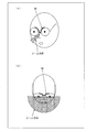
図9及び図10は、従来技術に係る眼鏡型の無線通信機におけるアンテナのビームの概略の放射方向(ビーム方向)の例を示す模式図である。 FIG. 9 and FIG. 10 are schematic diagrams illustrating an example of a schematic radiation direction (beam direction) of an antenna beam in a glasses-type wireless communication device according to the related art.
特許文献1に記載のような眼鏡型の無線通信機では、アンテナのアンテナ素子90は、図9(a)に示すように、ユーザの鼻の近傍にある。この場合、アンテナ素子90がユーザの顔の前方にあるため、図9(b)に示すように、アンテナ素子90が送受信できるビーム方向の範囲は、ユーザの頭部の影響を受け、アンテナ素子90を中心に、ユーザの顔の前面方向の空間(全方向の半分程度の空間)になる。
In the spectacle-type wireless communication device described in Patent Document 1, the
また、特許文献2に記載のような眼鏡型の無線通信機では、アンテナのアンテナ素子90は、図10(a)に示すように、ユーザの耳の近傍にある。この場合、アンテナ素子90がユーザの顔の側面にあるため、図10(b)に示すように、アンテナ素子90が送受信できるビーム方向の範囲は、ユーザの頭部の影響を受け、アンテナ素子90を中心に、ユーザの顔の側面方向の空間(全方向の半分程度の空間)になる。
Further, in the glasses-type wireless communication device described in
このように、従来技術では、アンテナのビーム方向が顔の前面方向または側面方向となるため、電波の到来方向次第では、送受信特性が低下するという問題がある。また、アンテナは、頭部に近接するため、アンテナ利得が低下するという問題がある。 Thus, in the prior art, since the beam direction of the antenna is the front direction or the side direction of the face, there is a problem that transmission / reception characteristics deteriorate depending on the arrival direction of the radio wave. Further, since the antenna is close to the head, there is a problem that the antenna gain is reduced.
本発明は、上記問題に鑑みてなされたものであり、その主たる目的は、アンテナ利得がよい眼鏡型無線通信機を実現することにある。 The present invention has been made in view of the above problems, and a main object thereof is to realize a glasses-type wireless communication apparatus having a good antenna gain.
上記課題を解決するために、本発明に係る眼鏡型無線通信機は、左右の接眼部、パッド、智、テンプル、及び、無線通信を行うためのアンテナ素子を備えている眼鏡型無線通信機であって、前記アンテナ素子が、前記接眼部の外周部に沿った領域であって、前記智を含み、かつ前記パッドとの接続部を含まない領域に配置されていることを特徴としている。 In order to solve the above-described problems, a glasses-type wireless communication device according to the present invention includes a glasses-type wireless communication device including left and right eyepieces, pads, wisdom, temples, and an antenna element for performing wireless communication. The antenna element is disposed in a region along the outer peripheral portion of the eyepiece portion, including the wisdom and not including a connection portion with the pad. .
上記構成によれば、ユーザの頭部の影響によるシャドウイングが低減され、アンテナの開放空間が広がる。すなわち、アンテナのビーム方向の制限が緩和され、電波の到来方向による送受信性能の劣化が解消されるという効果を奏する。 According to the above configuration, shadowing due to the influence of the user's head is reduced, and the open space of the antenna is widened. That is, the restriction on the beam direction of the antenna is relaxed, and the deterioration of the transmission / reception performance due to the arrival direction of the radio wave is eliminated.
すなわち、アンテナ素子を、前記接眼部の外周に沿った領域であって、前記智を含み、かつ前記パッドとの接続部を含まない領域に配置することにより、眼鏡において頭部に最も接近する部位(例えば、パッドおよびテンプル)を避け、頭部から離れており、ユーザの頭部の影響によるシャドウイングが低減され得る位置にアンテナ素子を配置することができるため、アンテナ利得が向上するという効果を奏する。 That is, by placing the antenna element in a region along the outer periphery of the eyepiece portion, including the wisdom and not including the connection portion with the pad, the antenna element is closest to the head in glasses. The antenna element can be arranged at a position where the shadowing due to the influence of the user's head can be reduced by avoiding the part (for example, pad and temple) and away from the head, thereby improving the antenna gain. Play.
本発明に係る眼鏡型無線通信機によれば、ユーザの頭部の影響によるシャドウイングが低減され、電波の到来方向による送受信性能の劣化が解消される。また、アンテナ素子が頭部から離れた場所に位置するため、アンテナ利得が向上する。 According to the eyeglass-type wireless communication device according to the present invention, shadowing due to the influence of the user's head is reduced, and deterioration of transmission / reception performance due to the arrival direction of radio waves is eliminated. Further, since the antenna element is located at a location away from the head, the antenna gain is improved.
以下、本発明の実施の形態について、詳細に説明する。本発明に係る眼鏡型無線通信機は、眼鏡の体裁を有し、無線通信を行うものであれば、特に限定されず、3D眼鏡、ヘッドマウントディスプレイ、ヘッドセット、ラジオ受信機、個人識別装置等様々な用途に適用し得る。
〔実施形態1〕
以下、本発明の一実施形態(実施形態1)について、図1から図5を参照して説明すれば、以下のとおりである。Hereinafter, embodiments of the present invention will be described in detail. The eyeglass-type wireless communication device according to the present invention is not particularly limited as long as it has the appearance of glasses and performs wireless communication. 3D glasses, a head-mounted display, a headset, a radio receiver, a personal identification device, and the like It can be applied to various uses.
Embodiment 1
Hereinafter, it will be as follows if one Embodiment (Embodiment 1) of this invention is described with reference to FIGS.
(眼鏡型無線通信機1の概略)
図2は、本実施形態における眼鏡型無線通信機1の概観図である。図2に示すように、眼鏡型無線通信機1は、眼鏡の体裁を有しており、接眼部11、リム12、ブリッジ13、テンプル14、モダン15、智16、蝶番17、パッド18、及び、クリングス19などを有する。(Outline of glasses-type wireless communication device 1)
FIG. 2 is an overview of the glasses-type wireless communication device 1 according to this embodiment. As shown in FIG. 2, the eyeglass-type wireless communication device 1 has the appearance of eyeglasses, and includes an
接眼部11は、左右の目の前に配置される光学部材であり、例えば、眼鏡型のレンズであり得、LCD(Liquid Crystal Display)、網膜操作ディスプレイなど、画像を表示するためのディスプレイに組み込まれているものであってもよい。
The
リム12は、接眼部11の周りを囲んで接眼部11を保持する保持部材である。リム12は、必ずしも接眼部11の周りの全てを保護している必要はなく、接眼部11の略半分、または一部のみを保護するものであってもよい。また、眼鏡型無線通信機1は、リム12を備えていなくともよい。
The
ブリッジ13は、左右の接眼部11を連結するための連結部材である。ブリッジ13は、リム12を介して、または介さずに、左右の接眼部11を所定の位置関係にて連結する。
The
テンプル14は、耳掛けを含んだ部材であり、ツルとも称される。また、テンプル14において、ユーザの耳に接する部分を、モダン15と称される被覆部材が被覆している場合もある。
The
智16は、接眼部11とテンプル14とを接続するための接続部材である。智16は、接眼部11の外周に沿った領域に設けられており、リム12と一体化されていてもよいし、独立して接眼部に結合していてもよい。
The
蝶番17は、接眼部11等に対してテンプル14を折りたたみ可能にするための開閉部材であり、智16とテンプル14との間に設けられている。
The
パッド18は、ユーザの鼻に接する部材である。
The
クリングス19は、パッド18と接眼部11とを連結する連結部材である。クリングス19は、リム12を介して、または介さずに、パッド18と接眼部11とを所定の位置関係にて連結する。また、眼鏡型無線通信機1は、クリングス19を備えていなくともよく、その場合、パッド18と接眼部11またはリム12とは直接結合され得る。
The
なお、各部は、例えば、一般の眼鏡と同じ材料で構成してもよいが、これに限定されない。例えば、リム12、ブリッジ13、及び、テンプル14の材料としては、例えば、金属(例えば、チタン、チタン合金、アルミニウム合金、マグネシウム合金、ニッケルクロム合金、及び、ステンレスなど)、プラスチック(例えば、エポキシ樹脂、セルロイド、アセテート、及び、ポリアミドなど)等を用いることができるが、これに限定されない。
In addition, although each part may be comprised with the same material as general spectacles, for example, it is not limited to this. For example, as the material of the
(眼鏡型無線通信機1の内部構成)
次に、眼鏡型無線通信機1の内部構成について、図1を参照して説明する。図1は、眼鏡型無線通信機1の内部構成を示す図である。なお、図1では、リム12を含まない構成の眼鏡型無線通信機について説明するが、本実施形態はこれに限定されず、リム12を含む構成であってもよい。但し、本実施形態において、リム12を設ける場合には、リム12は、プラスチック等の絶縁体によって構成することが好ましい。これにより、アンテナ特性をより向上させることができる。(Internal configuration of the glasses-type wireless communication device 1)
Next, the internal configuration of the glasses-type wireless communication device 1 will be described with reference to FIG. FIG. 1 is a diagram illustrating an internal configuration of the glasses-type wireless communication device 1. In addition, although the spectacles type | mold radio | wireless communication apparatus of the structure which does not contain the rim |
図1に示すように、眼鏡型無線通信機1は、アンテナ100を有している。アンテナ100は、アンテナ100に電力を供給する電源部101、電気信号を制御する制御部102、アンテナ素子105を介してデータの送受信を行う無線部103、電源部101からの電力をアンテナ素子105に供給する給電線路104、及び、アンテナ素子105を備えた、ダイポールアンテナである。
As shown in FIG. 1, the eyeglass-type wireless communication device 1 has an
図1に示すように、電源部101、制御部102、及び、無線部103は、テンプル14に配置されている。給電線路104は、テンプル14から智16を介し、アンテナ素子105に接続している。
As shown in FIG. 1, the
アンテナ素子105は、智16を中心に、接眼部11の外周に沿って配置されている。アンテナ素子105は、智16から接眼部11の鉛直上部側に延びるアンテナ素子(第1のアンテナ素子)105aと、智16から接眼部11の鉛直下部側に延びるアンテナ素子(第2のアンテナ素子)105bとから構成される。つまり、アンテナ素子105a及び105bは、対になって智16を挟むように配置されている。なお、接眼部11の外周とは、ユーザの眼に対向する面における外周を指す。
The
なお、本実施形態では、アンテナ素子105は、図1に示すように接眼部11の側端面に配置されているが、本発明はこれに限定されない。例えば、図11に示すように、アンテナ素子105は、接眼部11におけるユーザの眼に対向する面(レンズ面)上に設けられていてもよい。また、接眼部の外周をリムが囲んでいる場合、アンテナ素子105は、接眼部11とリム12との間に設けられていてもよいし、リム12の内部または外部に設けられていてもよい。このように、本発明において、アンテナ素子105は、接眼部11の外周に沿って配置されていればよく、設置される先の部材および面は特に限定されない。但し、アンテナ素子105の少なくとも一部を、接眼部11とリム12との間、または、リム12の中に形成することにより、アンテナ素子105が外部に露出することがないため、眼鏡型無線通信機1の美観、及び耐久性を向上させることができる。また、アンテナ素子105が突き出すなど、眼鏡の体裁が崩れることを好適に防ぐことができる。
In the present embodiment, the
また、本実施形態では、アンテナ素子105a及び105bは、図1に示すように、何れも角が丸くなったL字形状を有している。しかしながら、他の実施形態において、アンテナ素子105a及びアンテナ素子105bは、形状および長さの少なくとも何れかが互いに異なってもよい。アンテナ素子をこのように構成することにより、2つのアンテナの共振周波数を異ならせることができるため、複数の周波数帯に対応させることができる。
In the present embodiment, the
なお、図1では、アンテナ素子105は、眼鏡型無線通信機1の左の接眼部11の外周に沿うように配置されているが、アンテナ素子105は右の接眼部11の外周に沿うように配置されていても良い。また、アンテナ素子105は、顔に接するパッド18との接続部(クリングス19との接続部)には配置されない。つまり、アンテナ素子105は、パッド18との接続部を除く左右の接眼部11の少なくとも一方の外周に沿うように配置されている。
In FIG. 1, the
このように、アンテナ素子105aおよび105bは、夫々、接眼部11の外周に沿った領域であって、智16を含み、かつパッド18との接続部を含まない領域に配置されており、智16から接眼部11の外周に沿って互いに異なる方向に延びている。アンテナ素子105aおよび105bの配置領域を、接眼部11の外周に沿った領域であって、智16を含み、かつパッド18との接続部を含まない領域とすることにより、アンテナ素子105aおよび105bを、ユーザの頭から遠く、後述するように、ユーザの頭部の影響によるシャドウイングが低減され得る場所に配置することができる。
As described above, the
ここで、アンテナ素子105(アンテナ素子105a及び105b)の半分以上の部分が、眼鏡型無線通信機1の智16側に配置されている。詳細に述べれば、アンテナ素子105の半分以上の体積を占める部分が、パッド18に比べて、給電線路104が設けられている智16の方に近い位置に配置されている。図1に示す眼鏡型無線通信機1では、アンテナ素子105は、およそ5分の4が、智16側に配置されている。
Here, more than half of the antenna element 105 (
(眼鏡型無線通信機1の効果)
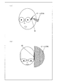
図1の眼鏡型無線通信機1を用いた場合の、ビーム方向の範囲を図3に示す。(Effect of glasses-type wireless communication device 1)
FIG. 3 shows the range of the beam direction when the glasses-type wireless communication device 1 of FIG. 1 is used.
図3(a)は、眼鏡型無線通信機1を使用した時のユーザの顔を斜めから見たときの一例を示す図であり、(b)は、ユーザを真上から見た場合のアンテナ素子105のビーム方向の図を示す。
FIG. 3A is a diagram illustrating an example when the user's face is viewed obliquely when the glasses-type wireless communication device 1 is used, and FIG. 3B is an antenna when the user is viewed from directly above. A diagram of the beam direction of
図3(a)に示すように、眼鏡型無線通信機1のアンテナ素子105は、智16を含み、かつパッド18との接続部を含まない領域に配置されている。すなわち、アンテナ素子105が、ユーザの頭部を上から見たときの外延部に配置されることになり、アンテナ素子105の概略のビーム方向は、図3(b)に示すように、アンテナ素子105を中心に、ユーザの顔の前面の方向と側面と方向とに及ぶ。このように、本実施形態に係る眼鏡型無線通信機1では、図9及び図10に示すような従来技術に係る眼鏡型の無線通信機に比べ、ユーザの頭部の影響によるシャドウイングが低減されており、アンテナの開放空間が広がっている。これにより、アンテナのビーム方向の制限が緩和され、電波の到来方向による送受信性能の劣化が解消される。
As shown in FIG. 3A, the
次に、図1の眼鏡型無線通信機1のアンテナ100のアンテナ利得を、図5を用いて説明する。図5は、周波数に対するアンテナ利得を示すグラフであり、アンテナ100のアンテナ利得を実線で示し、図9のように配置されたアンテナ90のアンテナ利得を点線で示す。また、図5において、横軸は周波数(MHz)を示し、縦軸はアンテナ利得(dBi)を示す。
Next, the antenna gain of the
図5に示すとおり、アンテナ100のアンテナ利得は、アンテナ90のアンテナ利得と比べ高くなっていることがわかる。これは、アンテナ素子105が、智16を含み、かつパッド18との接続部を含まない領域に配置されていることにより、アンテナ素子105が頭部から離れた場所に位置するため、ユーザの頭部のGNDとしての影響が低減し、アンテナ利得が向上するためである。特に、アンテナ素子105は、パッド18、テンプル14といったユーザに直接接触する場所には設けられていない。これにより、好適にアンテナ利得を向上させることができる。
As shown in FIG. 5, it can be seen that the antenna gain of the
また、アンテナ100(のアンテナ素子105a及び105b)は、ダイポールアンテナを構成する。このように、アンテナ100がダイポールアンテナとして働くことにより、GNDの形状(眼鏡型無線通信機1の形状)の影響を低減することができる。また、アンテナ100がダイポールアンテナとして働くことにより、アンテナ100のビームの方向の制御が容易になり、ユーザの顔の正面方向へのビームを絞ることができる。これによって、アンテナ100のアンテナ特性をより向上することができる。
The antenna 100 (the
また、アンテナ素子105a及びアンテナ素子105bは、ダイバーシチアンテナを構成してもよい。このように、アンテナ素子105aとアンテナ素子105bとでMIMO等のダイバーシチアンテナを構成することにより、さらに送受信特性を向上させることができる。
Further, the
(変形例)
また、上記では、アンテナ素子105を2つのアンテナ素子(アンテナ素子105a及び105b)から構成する場合について説明したが、本発明はこれに限定されず、例えば、モノポールアンテナとして使用することになるが、アンテナ素子105は、智16の上方に設けられたもの(アンテナ素子105a)、及び、智16の下方に設けられたもの(アンテナ素子105b)の何れか一つであってもよい。この場合であっても、上述したように、アンテナ素子105は、ユーザの頭部の影響によるシャドウイングを低減することができる位置に配置されているため、良好なアンテナ特性を得ることができる。(Modification)
In the above description, the
また、更なるアンテナ素子を備えていてもよい。 Further, an additional antenna element may be provided.
なお、アンテナ素子105(のアンテナ素子105a及び105b)の長さは、図1に示すものに限定されず、パッド18との接続部を除く接眼部11の外周に沿った領域に配置されていると共に、アンテナ素子105が、智16を含み、かつパッド18との接続部を含まない領域に配置されている限り、無線通信を行う周波数帯に応じて適宜長さを設定することができる。
The length of the antenna element 105 (the
図4は、図1に示す眼鏡型無線通信機1よりも使用周波数帯が高い眼鏡型無線通信機1’の概略構成を示す図である。図4に示すように、アンテナ100’のアンテナ素子105’の長さは、図1のアンテナ素子105の長さより短い。このようなアンテナ素子105’は、全てが智16側に配置されている(アンテナ素子105a及び105bの全体が、パッド18に比べて、智16の方に近い位置に配置されている)。
FIG. 4 is a diagram illustrating a schematic configuration of a glasses-type wireless communication device 1 ′ having a higher use frequency band than the glasses-type wireless communication device 1 illustrated in FIG. 1. As shown in FIG. 4, the length of the antenna element 105 'of the antenna 100' is shorter than the length of the
このような眼鏡型無線通信機1’においても、眼鏡型無線通信機1と同様、図3に示すようなビーム方向の範囲を有し、電波の到来方向による送受信性能の劣化が解消される。また、アンテナ素子105’がユーザの頭部から離れた場所に位置するため、アンテナ利得が向上する。
Such a glasses-type wireless communication device 1 ′ also has a beam direction range as shown in FIG. 3 like the glasses-type wireless communication device 1, and the degradation of transmission / reception performance due to the arrival direction of radio waves is eliminated. Further, since the
〔実施形態2〕
本発明の他の実施形態(実施形態2)について、図6から図8を参照して説明する。[Embodiment 2]
Another embodiment (second embodiment) of the present invention will be described with reference to FIGS.
実施形態1では、智16を中心に接眼部11の上部及び下部にアンテナ素子105が配置されているアンテナ100を有した眼鏡型無線通信機1について説明を行ったが、本発明はこれに限定されない。例えば、眼鏡型無線通信機1は、ブリッジ13を中心に接眼部11の上部及び/または下部にアンテナ素子が配置されているアンテナを有していてもよい。
In the first embodiment, the spectacles-type wireless communication device 1 having the
本実施形態では、ブリッジ13を中心に左右の接眼部11夫々の上部及び/または下部にアンテナ素子205が配置されている眼鏡型無線通信機2について説明を行う。なお、本実施形態において、接眼部11、リム12、ブリッジ13、テンプル14、モダン15、智16、蝶番17、パッド18、及び、クリングス19といった部材は、実施形態1と同様の構成を有する。
In the present embodiment, a description will be given of the eyeglass-type
(眼鏡型無線通信機2の内部構成)
眼鏡型無線通信機2の内部構成について、図6を参照して説明する。図6は、眼鏡型無線通信機2の内部構成を示す図である。なお、図6では、眼鏡型無線通信機2がリム12を含む構成について説明するが、本実施形態に係る眼鏡型無線通信機2は、リム12を含まない構成であってもよい。また、本実施形態において、リム12は、金属によって構成され得る。(Internal configuration of the glasses-type wireless communication device 2)
The internal configuration of the glasses-type
図6に示すように、眼鏡型無線通信機2は、アンテナ200を有している。アンテナ200は、電源部201、制御部202、無線部203、給電線路204、及び、アンテナ素子205を備えている。なお、アンテナ200の各部はアンテナ100の各部と同様の処理を行う。また、アンテナ200は、リム12、ブリッジ13等の金属部を接地素子(GND)とした2つのモノポールアンテナから構成される。
As shown in FIG. 6, the eyeglass-type
図6に示すように、電源部201、制御部202、及び、無線部203は、接眼部11の間(ブリッジ13)に配置されている。給電線路204は、左右の接眼部11の間に位置するブリッジ13からリム12を介してアンテナ素子205に接続している。
As illustrated in FIG. 6, the
アンテナ素子205は、ブリッジ13を中心に、左右の接眼部11の鉛直上部側の各々に配置されている。アンテナ素子105は、左の接眼部11の外周に沿うように配置されたアンテナ素子(第3のアンテナ素子)205Lと、右の接眼部11の外周に沿うように配置されたアンテナ素子(第4のアンテナ素子)205Rとから構成される。
The
図6に示すように、アンテナ素子205Lは、左の接眼部11の上部に配置され、アンテナ素子205Rは、右の接眼部11の上部に配置されている。つまり、アンテナ素子205は、ブリッジ13を中心に左右の接眼部11の各々の鉛直上部側の外周に沿って配置されている。
As shown in FIG. 6, the
また、アンテナ素子205は、智16を含み、かつパッド18との接続部を含まない領域に配置されている。特に、アンテナ素子205の体積の半分以上を占める部分が、パッド18よりも智16に近い位置に配置されていることが好ましい。図6に示すように、アンテナ素子205(アンテナ素子205L及び205R)は、智16を含む領域に設けられているとともに、およそ5分の4が智16側に配置されている。
Further, the
なお、アンテナ素子205の半分以上の部分が智16側に配置されているとは、詳細に述べれば、アンテナ素子205Lの半分以上の体積を占める部分が、パッド18よりも、アンテナ素子205Lが配置されている左の接眼部11の側部に設けられた智16の方に近い位置に配置されており、アンテナ素子205Rの半分以上の部分が、パッド18よりも、アンテナ素子205Rが配置されている右の接眼部11の側部に設けられた智16の方に近い位置に配置されていることを指す。
More specifically, the fact that more than half of the
(眼鏡型無線通信機2の効果)
図6の眼鏡型無線通信機2を用いた場合の、ビーム方向の概略の範囲を図7に示す。(Effect of glasses-type wireless communication device 2)
FIG. 7 shows a schematic range of the beam direction when the glasses-type
図7(a)は、眼鏡型無線通信機2を使用した時のユーザの顔を斜めから見たときの一例を示す図であり、(b)は、ユーザを真上から見た場合のアンテナ素子205のビーム方向の図を示す。
FIG. 7A is a diagram illustrating an example when the user's face is viewed obliquely when the glasses-type
図7(a)に示すように、眼鏡型無線通信機2のアンテナ素子205は、眼鏡型無線通信機2の両サイドに夫々設けられ、智16を含み、かつパッド18との接続部を含まない領域に配置されている。すなわち、アンテナ素子205が、ユーザの頭部を上から見たときの外延部の両サイドに配置されることになり、このときのアンテナ素子205のビーム方向は、図7(b)に示すように、左右のアンテナ素子を中心に、ユーザの顔の周囲のほぼ全方向に及ぶ。
As shown in FIG. 7A, the
このように、本実施形態に係る眼鏡型無線通信機2では、図9及び図10に示すような従来技術に係る眼鏡型の無線通信機、及び、実施形態1に係る眼鏡型無線通信機1に比べ、ユーザの頭部の影響によるシャドウイングが低減されており、アンテナの開放空間が広がっている。これにより、アンテナのビーム方向の制限がより緩和され、電波の到来方向による送受信性能の劣化が好適に解消される。これにより、アンテナ素子205によって送受信する無線の強度を増強することができる。
As described above, in the glasses-type
また、実施形態1に係る眼鏡型無線通信機1と同様、智16を含み、かつパッド18との接続部を含まない領域に配置されていることにより、アンテナ素子205が頭部から離れた場所に位置するため、ユーザの頭部のGNDとしての影響が低減し、アンテナ利得が向上する。特に、アンテナ素子205は、パッド18、テンプル14といったユーザに直接接触する場所には設けられていない。これにより、好適にアンテナ利得を向上させることができる。
Similarly to the glasses-type wireless communication device 1 according to the first embodiment, the
なお、アンテナ素子205R及びアンテナ素子205Lは、ダイバーシチアンテナを構成してもよい。このように、アンテナ素子205Rとアンテナ素子205LとでMIMO等のダイバーシチアンテナを構成することにより、さらに送受信特性を向上させることができる。
The
(変形例)
図6では、アンテナ素子205R及びアンテナ素子205Lは、同じ形状であるように描写されているが、本発明はこれに限定されず、アンテナ素子205R及びアンテナ素子205Lを、形状および長さの少なくとも何れかが互いに異なるように構成することにより、2つのアンテナの共振周波数を異ならせ、複数の周波数帯に対応させてもよい。(Modification)
In FIG. 6, the
また、上記では、アンテナ素子205を2つのアンテナ素子(アンテナ素子205R及び205L)から構成する構成について説明したが、本発明はこれに限定されず、例えば、アンテナの開放空間は減少するが、アンテナ素子205は、右の接眼部に設けられたもの(アンテナ素子205R、205R’)及び左の接眼部に設けられたもの(アンテナ素子205L、205L’)の何れか一つであってもよい。
In the above description, the configuration in which the
また、さらなるアンテナ素子を備えていてもよい。例えば、実施形態1のアンテナ100と、実施形態2のアンテナ200とを組み合わせてもよい。すなわち、実施形態2に係る眼鏡型無線通信機2において、アンテナ素子105及び無線部103を更に備えていてもよい。
Further, an additional antenna element may be provided. For example, the
なお、図6に示す眼鏡型無線通信機2では、アンテナ素子205が左右の接眼部11の鉛直上部側の外周に沿うように配置されているが、アンテナ素子205は、鉛直下部側の外周に沿うように配置されてもよい。また、一方は、接眼部11の鉛直上部側の外周に沿うように配置され、他方は、接眼部11の鉛直下部側の外周に沿うように配置されるという、左右非対称な配置であってもよい。
In the glasses-type
図8に、アンテナ素子205R’が接眼部11の鉛直上部側の外周に沿うように配置され、アンテナ素子205L’が接眼部11の鉛直下部側の外周に沿うように配置された眼鏡型無線通信機2’(のアンテナ200’及びアンテナ素子205’)を示す。図8に示すように、アンテナ素子205R’は、右の接眼部11の鉛直上部側の外周に沿うように配置され、アンテナ素子205L’は、左の接眼部11の鉛直下部側の外周に沿うように配置されている。
In FIG. 8, an
このような眼鏡型無線通信機2’においても、眼鏡型無線通信機2と同様、図7に示すようなビーム方向の範囲を有し、電波の到来方向による送受信性能の劣化が解消される。また、アンテナ素子205’がユーザの頭部から離れた場所に位置するため、アンテナ利得が向上する。
Such a glasses-type
なお、前述したようにまた、実施形態1及び2において、接眼部11の外周を囲むリム12を備え、アンテナ素子105及びアンテナ素子205の少なくとも一部が、接眼部11とリム12との間に設けられていてもよいし、リムの内部または外部に設けられていてもよい。このように、本発明において、アンテナ素子105及びアンテナ素子205は、接眼部11の外周に沿って配置されていればよく、設置される先の部材および面は特に限定されない。但し、アンテナ素子105及びアンテナ素子205の少なくとも一部を、接眼部11とリム12との間、または、リム12の中に形成することにより、アンテナ素子105及びアンテナ素子205が外部に露出することがないため、眼鏡型無線通信機1及び眼鏡型無線通信機2の美観、及び耐久性を向上させることができる。また、アンテナ素子105及びアンテナ素子205が突き出すなど、眼鏡の体裁が崩れることを好適に防ぐことができる。
In addition, as described above, in the first and second embodiments, the
(本発明の好ましい形態)
以上のように、本発明に係る眼鏡型無線通信機は、左右の接眼部、パッド、智、テンプル、及び、無線通信を行うためのアンテナ素子を備えている眼鏡型無線通信機であって、前記アンテナ素子が、前記接眼部の外周部に沿った領域であって、前記智を含み、かつ前記パッドとの接続部を含まない領域に配置されていることを特徴としている。(Preferred form of the present invention)
As described above, the glasses-type wireless communication device according to the present invention is a glasses-type wireless communication device including the left and right eyepieces, pads, wisdom, temples, and an antenna element for performing wireless communication. The antenna element is arranged in a region along the outer peripheral portion of the eyepiece portion, the region including the wisdom and not including the connection portion with the pad.
上記構成によれば、ユーザの頭部の影響によるシャドウイングが低減され、アンテナの開放空間が広がる。すなわち、アンテナのビーム方向の制限が緩和され、電波の到来方向による送受信性能の劣化が解消されるという効果を奏する。 According to the above configuration, shadowing due to the influence of the user's head is reduced, and the open space of the antenna is widened. That is, the restriction on the beam direction of the antenna is relaxed, and the deterioration of the transmission / reception performance due to the arrival direction of the radio wave is eliminated.
すなわち、アンテナ素子を、前記接眼部の外周に沿った領域であって、前記智を含み、かつ前記パッドとの接続部を含まない領域に配置することにより、眼鏡において頭部に最も接近する部位(例えば、パッドおよびテンプル)を避け、頭部から離れており、ユーザの頭部の影響によるシャドウイングが低減され得る位置にアンテナ素子を配置することができるため、アンテナ利得が向上するという効果を奏する。 That is, by placing the antenna element in a region along the outer periphery of the eyepiece portion, including the wisdom and not including the connection portion with the pad, the antenna element is closest to the head in glasses. The antenna element can be arranged at a position where the shadowing due to the influence of the user's head can be reduced by avoiding the part (for example, pad and temple) and away from the head, thereby improving the antenna gain. Play.
また、本発明に係る眼鏡型無線通信機では、前記アンテナ素子の半分以上の部分が、前記パッドよりも前記智に近い位置に配置されていることが好ましい。 Moreover, in the spectacles type radio | wireless communication apparatus which concerns on this invention, it is preferable that the half or more part of the said antenna element is arrange | positioned in the position near the said wisdom rather than the said pad.
上記構成によれば、アンテナ素子の半分以上の体積を占める部分が、よりユーザの頭部の影響によるシャドウイングが低減され得る智側に位置するため、好適にアンテナ利得を向上させることができる。 According to the above configuration, the portion occupying more than half the volume of the antenna element is located on the wisdom side where shadowing due to the influence of the user's head can be further reduced, and therefore the antenna gain can be improved suitably.
また、本発明に係る眼鏡型無線通信機では、前記アンテナ素子には、前記智から前記接眼部の外周に沿って一方向に延びる第1のアンテナ素子が含まれており、前記第1のアンテナ素子に電力を供給する給電線路は、前記テンプルに設けられている無線部から前記智を介して前記第1のアンテナ素子に接続していてもよい。 In the glasses-type radio communication device according to the present invention, the antenna element includes a first antenna element extending in one direction along the outer periphery of the eyepiece from the wisdom. A feed line for supplying power to the antenna element may be connected to the first antenna element via the wisdom from a radio unit provided in the temple.
上記構成によれば、テンプルに無線部を実装した場合であっても、ユーザの頭部の影響によるシャドウイングが低減され得る場所にアンテナ素子を設けることができるため、電波の到来方向による送受信性能の劣化の解消、アンテナ利得の向上といった効果を好適に得ることができる。 According to the above configuration, even when the radio unit is mounted on the temple, the antenna element can be provided at a place where shadowing due to the influence of the user's head can be reduced. It is possible to suitably obtain effects such as elimination of deterioration and improvement of antenna gain.
また、上記眼鏡型無線通信機では、前記アンテナ素子には、前記智から前記接眼部の外周に沿って前記第1のアンテナ素子とは反対方向に延びる第2のアンテナ素子がさらに含まれており、前記第2のアンテナ素子に電力を供給する給電線路は、前記テンプルに設けられている無線部から前記智を介して前記第2のアンテナ素子に接続していてもよい。 In the glasses-type radio communication device, the antenna element further includes a second antenna element extending in the opposite direction from the first antenna element along the outer periphery of the eyepiece from the wisdom. The feeding line for supplying power to the second antenna element may be connected to the second antenna element through the wisdom from a radio unit provided in the temple.
上記構成によれば、テンプルに無線部を実装した場合であっても、ユーザの頭部の影響によるシャドウイングが低減され得る場所にアンテナ素子を設けることができるため、電波の到来方向による送受信性能の劣化の解消、アンテナ利得の向上といった効果を好適に得ることができるほか、ダイポールアンテナを容易に構成することができるため、GNDの形状(眼鏡型無線通信機の形状)の影響を低減することができる上、ビームの方向の制御が容易になる。すなわち、上記構成では、前記第1及び第2のアンテナ素子は、ダイポールアンテナを構成することが好ましい。 According to the above configuration, even when the radio unit is mounted on the temple, the antenna element can be provided at a place where shadowing due to the influence of the user's head can be reduced. The effect of eliminating the deterioration of the antenna and improving the antenna gain can be suitably obtained, and since the dipole antenna can be easily configured, the influence of the shape of the GND (the shape of the glasses-type wireless communication device) can be reduced. In addition, the beam direction can be easily controlled. In other words, in the above configuration, it is preferable that the first and second antenna elements constitute a dipole antenna.
また、前記第1及び第2のアンテナ素子は、形状および長さの少なくとも何れかが互いに異なってもよい。上記構成によれば、2つのアンテナの共振周波数を異ならせることにより、複数の周波数帯に対応させることができる。 Further, the first and second antenna elements may be different from each other in at least one of shape and length. According to the said structure, it can be made to respond | correspond to a some frequency band by varying the resonant frequency of two antennas.
また、前記第1及び第2のアンテナ素子は、ダイバーシチアンテナを構成してもよい。このように、第1のアンテナと第2のアンテナとでMIMO等のダイバーシチアンテナを構成することにより、さらに送受信特性を向上させることができる。 The first and second antenna elements may constitute a diversity antenna. In this way, by configuring a diversity antenna such as MIMO with the first antenna and the second antenna, transmission / reception characteristics can be further improved.
また、本発明に係る眼鏡型無線通信機では、前記アンテナ素子には、前記左右の接眼部のうちの一方の接眼部の外周に沿って配置されている第3のアンテナ素子が含まれており、前記第3のアンテナ素子に電力を供給する給電線路は、前記左右の接眼部の間に設けられている無線部から前記第3のアンテナ素子に接続していてもよい。 In the glasses-type wireless communication device according to the present invention, the antenna element includes a third antenna element arranged along an outer periphery of one of the left and right eyepieces. The feeder line for supplying electric power to the third antenna element may be connected to the third antenna element from a radio unit provided between the left and right eyepieces.
上記構成によれば、左右の接眼部の間(例えば、ブリッジ)に無線部を実装した場合であっても、ユーザの頭部の影響によるシャドウイングが低減され得る場所にアンテナ素子を設けることができるため、電波の到来方向による送受信性能の劣化の解消、アンテナ利得の向上といった効果を好適に得ることができる。 According to the above configuration, even when the radio unit is mounted between the left and right eyepieces (for example, a bridge), the antenna element is provided in a place where shadowing due to the influence of the user's head can be reduced. Therefore, it is possible to suitably obtain effects such as elimination of deterioration of transmission / reception performance due to the arrival direction of radio waves and improvement of antenna gain.
また、上記眼鏡型無線通信機では、前記アンテナ素子には、前記第3のアンテナ素子とは異なる接眼部の外周に沿って配置されている第4のアンテナ素子が含まれており、前記第4のアンテナ素子に電力を供給する給電線路は、前記左右の接眼部の間に設けられている無線部から前記第4のアンテナ素子に接続していてもよい。 In the glasses-type radio communication device, the antenna element includes a fourth antenna element arranged along an outer periphery of an eyepiece different from the third antenna element. The feed line for supplying power to the four antenna elements may be connected to the fourth antenna element from a radio unit provided between the left and right eyepieces.
上記構成によれば、左右の接眼部の間(例えば、ブリッジ)に無線部を実装した場合であっても、ユーザの頭部の影響によるシャドウイングが低減され得る場所にアンテナ素子を設けることができるため、電波の到来方向による送受信性能の劣化の解消、アンテナ利得の向上といった効果を好適に得ることができる。特に、上記の構成によれば、ユーザの頭部の両サイドにアンテナ素子が配置されるため、開放空間をより広くすることができ、頭部のシャドーイングの影響をさらに低減することができる。これにより、電波の到来方向による送受信性能の劣化をより効果的に解消することができる。上記構成において、前記第3及び第4のアンテナ素子は、夫々、モノポールアンテナを構成することが好ましい。 According to the above configuration, even when the radio unit is mounted between the left and right eyepieces (for example, a bridge), the antenna element is provided in a place where shadowing due to the influence of the user's head can be reduced. Therefore, it is possible to suitably obtain effects such as elimination of deterioration of transmission / reception performance due to the arrival direction of radio waves and improvement of antenna gain. In particular, according to the above configuration, the antenna elements are arranged on both sides of the user's head, so that the open space can be made wider and the influence of shadowing on the head can be further reduced. Thereby, the deterioration of the transmission / reception performance due to the arrival direction of the radio wave can be more effectively eliminated. In the above configuration, it is preferable that the third and fourth antenna elements each constitute a monopole antenna.
また、前記第3及び第4のアンテナ素子は、形状および長さの少なくとも何れかが互いに異なってもよい。上記構成によれば、2つのアンテナの共振周波数を異ならせることにより、複数の周波数帯に対応させることができる。 The third and fourth antenna elements may be different from each other in at least one of shape and length. According to the said structure, it can be made to respond | correspond to a some frequency band by varying the resonant frequency of two antennas.
また、前記第3及び第4のアンテナ素子は、ダイバーシチアンテナを構成してもよい。このように、第3のアンテナと第4のアンテナとでMIMO等のダイバーシチアンテナを構成することにより、さらに送受信特性を向上させることができる。 The third and fourth antenna elements may constitute a diversity antenna. In this way, by configuring a diversity antenna such as MIMO with the third antenna and the fourth antenna, transmission / reception characteristics can be further improved.
また、本発明における眼鏡型無線通信機は、前記接眼部の周りを囲むリムを備え、前記アンテナ素子の少なくとも一部が、前記接眼部と、前記リムとの間に配置されていてもよい。また、前記アンテナ素子の少なくとも一部が、前記リムの中に形成されていてもよい。 The glasses-type wireless communication device according to the present invention may include a rim that surrounds the eyepiece, and at least a part of the antenna element may be disposed between the eyepiece and the rim. Good. Further, at least a part of the antenna element may be formed in the rim.
上記の構成によれば、眼鏡型無線通信機においてアンテナ素子を好適に配置することができる。すなわち、アンテナ素子が外部に露出することがないため、眼鏡型無線通信機の美観、及び耐久性を向上させることができる。また、アンテナ素子が突き出すなど、眼鏡の体裁が崩れることを好適に防ぐことができる。 According to said structure, an antenna element can be arrange | positioned suitably in spectacles type | mold radio | wireless communication apparatus. That is, since the antenna element is not exposed to the outside, it is possible to improve the beauty and durability of the glasses-type wireless communication device. In addition, it is possible to suitably prevent the appearance of the glasses from collapsing, such as an antenna element protruding.
本発明は上述した各実施形態に限定されるものではなく、請求項に示した範囲で種々の変更が可能であり、異なる実施形態にそれぞれ開示された技術的手段を適宜組み合わせて得られる実施形態についても本発明の技術的範囲に含まれる。 The present invention is not limited to the above-described embodiments, and various modifications are possible within the scope shown in the claims, and embodiments obtained by appropriately combining technical means disclosed in different embodiments. Is also included in the technical scope of the present invention.
本発明は、3次元眼鏡、ゲーム用眼鏡、ヘッドマウントディスプレイ、ヘッドセット、ラジオ受信機、個人識別装置等の製造分野において利用することができる。 The present invention can be used in the field of manufacturing three-dimensional glasses, game glasses, head mounted displays, headsets, radio receivers, personal identification devices, and the like.
1、1’ 眼鏡型無線通信機
11 接眼部
12 リム
13 ブリッジ
14 テンプル
15 モダン
16 智
17 蝶番
18 パッド
19 クリングス
100、100’ アンテナ
101 電源部
102 制御部
103 無線部
104 給電線路
105、105’ アンテナ素子
(105a 第1のアンテナ素子)
(105b 第2のアンテナ素子)
2、2’ 眼鏡型無線通信機
200、200’ アンテナ
201 電源部
202 制御部
203 無線部
204 給電線路
205、205’ アンテナ素子
(205R、205R’ 第3のアンテナ素子)
(205L、205L’ 第4のアンテナ素子)
DESCRIPTION OF SYMBOLS 1, 1 'Glasses type radio |
(105b second antenna element)
2, 2 ′ glasses-type
(205L, 205L ′ fourth antenna element)
Claims (13)
前記アンテナ素子が、前記接眼部の外周に沿った領域であって、前記智を含み、かつ前記パッドとの接続部を含まない領域に配置されており、
テンプルをさらに備えており、
前記アンテナ素子には、前記智から前記接眼部の外周に沿って一方向に延びる第1のアンテナ素子が含まれており、
前記第1のアンテナ素子に電力を供給する給電線路は、前記テンプルに設けられている無線部から前記智を介して前記第1のアンテナ素子に接続しており、
前記アンテナ素子には、前記智から前記接眼部の外周に沿って前記第1のアンテナ素子とは反対方向に延びる第2のアンテナ素子がさらに含まれており、
前記第2のアンテナ素子に電力を供給する給電線路は、前記テンプルに設けられている無線部から前記智を介して前記第2のアンテナ素子に接続していることを特徴とする眼鏡型無線通信機。 An eyepiece-type wireless communication device including an eyepiece, a pad, wisdom, and an antenna element for performing wireless communication,
The antenna element is an area along the outer periphery of the eyepiece, including the wisdom, and disposed in an area not including a connection with the pad,
It is further equipped with temples,
The antenna element includes a first antenna element extending in one direction from the wi along the outer periphery of the eyepiece,
The power supply line for supplying power to the first antenna element is connected to the first antenna element via the wisdom from a radio unit provided in the temple.
The antenna element further includes a second antenna element extending in the opposite direction from the first antenna element along the outer periphery of the eyepiece from the wisdom,
Said second antenna element feed lines for supplying power to the eyeglass type you characterized in that it is connected to the second antenna element via the endpiece from the radio unit that is provided on the temple Wireless communication device.
前記アンテナ素子が、前記接眼部の外周に沿った領域であって、前記智を含み、かつ前記パッドとの接続部を含まない領域に配置されており、
前記接眼部には、左右の接眼部が含まれており、
前記アンテナ素子には、前記左右の接眼部のうちの一方の接眼部の外周に沿って配置されている第3のアンテナ素子が含まれており、
前記第3のアンテナ素子に電力を供給する給電線路は、前記左右の接眼部の間に設けられている無線部から前記第3のアンテナ素子に接続しており、
前記アンテナ素子には、前記第3のアンテナ素子とは異なる接眼部の外周に沿って配置されている第4のアンテナ素子が含まれており、
前記第4のアンテナ素子に電力を供給する給電線路は、前記左右の接眼部の間に設けられている無線部から前記第4のアンテナ素子に接続していることを特徴とする眼鏡型無線通信機。 An eyepiece-type wireless communication device including an eyepiece, a pad, wisdom, and an antenna element for performing wireless communication,
The antenna element is an area along the outer periphery of the eyepiece, including the wisdom, and disposed in an area not including a connection with the pad,
The eyepiece includes left and right eyepieces,
The antenna element includes a third antenna element disposed along an outer periphery of one of the left and right eyepieces,
A feed line that supplies power to the third antenna element is connected to the third antenna element from a radio unit provided between the left and right eyepieces,
The antenna element includes a fourth antenna element disposed along an outer periphery of an eyepiece different from the third antenna element,
Said fourth antenna element feed lines for supplying power to the eye mirror you characterized in that it is connected to the fourth antenna element from the radio unit that is provided between the left and right eyepieces Type wireless communication device.
前記アンテナ素子が、前記接眼部の外周に沿った領域であって、前記智を含み、かつ前記パッドとの接続部を含まない領域に配置されており、
前記アンテナ素子は、ユーザに直接接触する場所には設けられていないことを特徴とする眼鏡型無線通信機。 An eyepiece-type wireless communication device including an eyepiece, a pad, wisdom, and an antenna element for performing wireless communication,
The antenna element is an area along the outer periphery of the eyepiece, including the wisdom, and disposed in an area not including a connection with the pad,
The antenna elements, eyeglass-type radio communication device you characterized by not provided in place of direct contact with the user.
前記アンテナ素子の少なくとも一部は、前記接眼部と、前記リムとの間に配置されていることを特徴とする請求項1〜10の何れか1項に記載の眼鏡型無線通信機。 Comprising a rim surrounding the eyepiece,
Wherein at least a portion of said antenna element, it said eyepiece, glasses-type radio communication device according to any one of claim 1 to 10, characterized in that it is disposed between the rim.
前記アンテナ素子の少なくとも一部は、前記リムの中に形成されていることを特徴とする請求項1〜10の何れか1項に記載の眼鏡型無線通信機。 Comprising a rim surrounding the eyepiece,
Wherein at least a portion of the antenna elements, glasses-type radio communication device according to any one of claim 1 to 10, characterized in that it is formed in the rim.
前記アンテナ素子は、前記パッドおよび前記テンプルの少なくとも何れか一方には設けられていないことを特徴とする請求項1〜12の何れか一項に記載の眼鏡型無線通信機。 Bei Eteori the temple,
The eyeglass-type wireless communication device according to any one of claims 1 to 12, wherein the antenna element is not provided on at least one of the pad and the temple.
Priority Applications (1)
| Application Number | Priority Date | Filing Date | Title |
|---|---|---|---|
| JP2012549817A JP5576948B2 (en) | 2010-12-22 | 2011-12-20 | Glasses type wireless communication device |
Applications Claiming Priority (4)
| Application Number | Priority Date | Filing Date | Title |
|---|---|---|---|
| JP2010286381 | 2010-12-22 | ||
| JP2010286381 | 2010-12-22 | ||
| JP2012549817A JP5576948B2 (en) | 2010-12-22 | 2011-12-20 | Glasses type wireless communication device |
| PCT/JP2011/079437 WO2012086619A1 (en) | 2010-12-22 | 2011-12-20 | Eyeglasses-type wireless communications apparatus |
Publications (2)
| Publication Number | Publication Date |
|---|---|
| JPWO2012086619A1 JPWO2012086619A1 (en) | 2014-05-22 |
| JP5576948B2 true JP5576948B2 (en) | 2014-08-20 |
Family
ID=46313888
Family Applications (1)
| Application Number | Title | Priority Date | Filing Date |
|---|---|---|---|
| JP2012549817A Active JP5576948B2 (en) | 2010-12-22 | 2011-12-20 | Glasses type wireless communication device |
Country Status (4)
| Country | Link |
|---|---|
| US (1) | US9024830B2 (en) |
| JP (1) | JP5576948B2 (en) |
| CN (1) | CN103168390B (en) |
| WO (1) | WO2012086619A1 (en) |
Cited By (1)
| Publication number | Priority date | Publication date | Assignee | Title |
|---|---|---|---|---|
| US12068531B2 (en) | 2021-11-05 | 2024-08-20 | Samsung Electronics Co., Ltd. | Wearable electronic device including variable ground |
Families Citing this family (36)
| Publication number | Priority date | Publication date | Assignee | Title |
|---|---|---|---|---|
| US11630366B2 (en) | 2009-12-22 | 2023-04-18 | View, Inc. | Window antennas for emitting radio frequency signals |
| US11732527B2 (en) | 2009-12-22 | 2023-08-22 | View, Inc. | Wirelessly powered and powering electrochromic windows |
| US20130271813A1 (en) | 2012-04-17 | 2013-10-17 | View, Inc. | Controller for optically-switchable windows |
| US11342791B2 (en) | 2009-12-22 | 2022-05-24 | View, Inc. | Wirelessly powered and powering electrochromic windows |
| JP5944134B2 (en) * | 2011-10-14 | 2016-07-05 | シャープ株式会社 | Wireless communication device |
| US11300848B2 (en) | 2015-10-06 | 2022-04-12 | View, Inc. | Controllers for optically-switchable devices |
| CN103856229A (en) * | 2012-12-07 | 2014-06-11 | 宏碁股份有限公司 | Glasses-type communication device |
| KR102102643B1 (en) * | 2013-11-12 | 2020-04-21 | 엘지전자 주식회사 | Glass Type Terminal |
| EP4145379A1 (en) | 2014-03-05 | 2023-03-08 | View, Inc. | Monitoring sites containing switchable optical devices and controllers |
| US10056054B2 (en) * | 2014-07-03 | 2018-08-21 | Federico Fraccaroli | Method, system, and apparatus for optimising the augmentation of radio emissions |
| US9590293B2 (en) * | 2014-09-16 | 2017-03-07 | Google Inc. | GPS/WiFi battery antenna |
| EP3224901B1 (en) * | 2014-11-25 | 2023-09-20 | View, Inc. | Window antennas |
| US11114742B2 (en) | 2014-11-25 | 2021-09-07 | View, Inc. | Window antennas |
| US20160204839A1 (en) * | 2015-01-12 | 2016-07-14 | Futurewei Technologies, Inc. | Multi-band Antenna for Wearable Glasses |
| CN108352889B (en) * | 2015-11-09 | 2021-09-10 | 索尼互动娱乐股份有限公司 | Main beam direction determining apparatus, head-mounted display, determining method, and storage medium |
| JP6576280B2 (en) * | 2016-03-24 | 2019-09-18 | 京セラ株式会社 | Electronics |
| JP2017175435A (en) * | 2016-03-24 | 2017-09-28 | 京セラ株式会社 | Electronic apparatus |
| US11156855B2 (en) | 2016-05-09 | 2021-10-26 | Oakley, Inc. | Modular wearable electronic devices, systems, and methods |
| US20180212314A1 (en) * | 2017-01-24 | 2018-07-26 | Intel Corporation | Wearable device sar reduction and antenna improvement |
| US10880716B2 (en) | 2017-02-04 | 2020-12-29 | Federico Fraccaroli | Method, system, and apparatus for providing content, functionalities, and services in connection with the reception of an electromagnetic signal |
| US10477602B2 (en) | 2017-02-04 | 2019-11-12 | Federico Fraccaroli | Method, system, and apparatus for providing content, functionalities and services in connection with the reception of an electromagnetic signal |
| CN110383579B (en) * | 2017-03-06 | 2021-12-10 | 斯纳普公司 | Wearable device antenna system |
| WO2019012766A1 (en) * | 2017-07-14 | 2019-01-17 | 株式会社村田製作所 | Rfid tag-attached spectacles and rfid tag-attached article |
| CN107331953B (en) * | 2017-07-25 | 2019-11-19 | 富士高实业有限公司 | A kind of wireless headset using short-tail helical antenna and short circuit L shape radiator |
| WO2019119154A1 (en) | 2017-12-22 | 2019-06-27 | North Inc. | Antenna designs for wearable heads-up displays |
| KR20200080565A (en) * | 2018-12-27 | 2020-07-07 | 삼성전자주식회사 | Method for performing wireless communications and electronic device supporting the same |
| EP3966963A2 (en) | 2019-05-09 | 2022-03-16 | View, Inc. | Antenna systems for controlled coverage in buildings |
| US11372251B2 (en) * | 2019-06-17 | 2022-06-28 | Google Llc | Systems, devices, and methods for electrical pathways between components in wearable heads-up displays |
| TW202206925A (en) | 2020-03-26 | 2022-02-16 | 美商視野公司 | Access and messaging in a multi client network |
| US11631493B2 (en) | 2020-05-27 | 2023-04-18 | View Operating Corporation | Systems and methods for managing building wellness |
| WO2022055690A1 (en) * | 2020-09-08 | 2022-03-17 | Carnelian Laboratories Llc | Electronic devices with frame antennas |
| KR20230077431A (en) | 2021-11-25 | 2023-06-01 | 삼성전자주식회사 | Electronic device comprising antenna |
| US20230238688A1 (en) * | 2022-01-24 | 2023-07-27 | Google Llc | Parasitic element to reduce coupling between antennae on an eyeglass frame |
| US20240097311A1 (en) * | 2022-05-06 | 2024-03-21 | Meta Platforms Technologies, Llc | Antenna for wearable electronic devices |
| US20230369748A1 (en) * | 2022-05-13 | 2023-11-16 | Meta Platforms Technologies, Llc | Apparatus, system, and method for swappable antenna design |
| US12028505B2 (en) * | 2022-06-30 | 2024-07-02 | Htc Corporation | Image sensing device and head-mounted display |
Citations (2)
| Publication number | Priority date | Publication date | Assignee | Title |
|---|---|---|---|---|
| JPS558142A (en) * | 1978-07-03 | 1980-01-21 | Nippon Telegr & Teleph Corp <Ntt> | Loudspeaker call system |
| JPH04211524A (en) * | 1989-12-15 | 1992-08-03 | Nippon Telegr & Teleph Corp <Ntt> | Portable radio equipment |
Family Cites Families (12)
| Publication number | Priority date | Publication date | Assignee | Title |
|---|---|---|---|---|
| JPS6016126Y2 (en) * | 1979-09-11 | 1985-05-20 | 松下電器産業株式会社 | eyeglass receiver |
| JPS62193220U (en) | 1986-05-28 | 1987-12-08 | ||
| US5020150A (en) * | 1989-11-07 | 1991-05-28 | John Shannon | Combination radio and eyeglasses |
| JPH05344449A (en) * | 1992-06-08 | 1993-12-24 | Mitsubishi Electric Corp | Eyeglass type portable television receiver |
| US6010216A (en) * | 1993-01-19 | 2000-01-04 | Jesiek; Daniel Stephen | "Hear speak" two-way voice radio communications eyeglasses |
| GB2291551B (en) * | 1994-06-24 | 1998-03-18 | Roscoe C Williams Limited | Electronic viewing aid |
| JP2007174612A (en) | 2005-11-28 | 2007-07-05 | Tetsuo Suda | Eyeglasses with transmitting/receiving function and portable transceiver |
| US20080055537A1 (en) * | 2006-08-31 | 2008-03-06 | Motorola, Inc. | System for transreceiving electromagnetic signals in a communication network |
| US20120169990A1 (en) * | 2011-01-05 | 2012-07-05 | Burnstein Tracey E | Electronic eyewear and footwear |
| US9248309B2 (en) * | 2011-02-04 | 2016-02-02 | Johnson & Johnson Vision Care, Inc. | Light therapy system including spectacle frames and contact lenses |
| JP5647578B2 (en) * | 2011-07-27 | 2015-01-07 | シャープ株式会社 | Wireless communication device |
| US20130265169A1 (en) * | 2012-04-10 | 2013-10-10 | Russell F. Mates | Eyewear Device Configured To Track Head Movement |
-
2011
- 2011-12-20 US US13/876,385 patent/US9024830B2/en not_active Expired - Fee Related
- 2011-12-20 CN CN201180052005.3A patent/CN103168390B/en not_active Expired - Fee Related
- 2011-12-20 JP JP2012549817A patent/JP5576948B2/en active Active
- 2011-12-20 WO PCT/JP2011/079437 patent/WO2012086619A1/en active Application Filing
Patent Citations (2)
| Publication number | Priority date | Publication date | Assignee | Title |
|---|---|---|---|---|
| JPS558142A (en) * | 1978-07-03 | 1980-01-21 | Nippon Telegr & Teleph Corp <Ntt> | Loudspeaker call system |
| JPH04211524A (en) * | 1989-12-15 | 1992-08-03 | Nippon Telegr & Teleph Corp <Ntt> | Portable radio equipment |
Cited By (1)
| Publication number | Priority date | Publication date | Assignee | Title |
|---|---|---|---|---|
| US12068531B2 (en) | 2021-11-05 | 2024-08-20 | Samsung Electronics Co., Ltd. | Wearable electronic device including variable ground |
Also Published As
| Publication number | Publication date |
|---|---|
| JPWO2012086619A1 (en) | 2014-05-22 |
| CN103168390A (en) | 2013-06-19 |
| US20130194141A1 (en) | 2013-08-01 |
| WO2012086619A1 (en) | 2012-06-28 |
| CN103168390B (en) | 2015-02-18 |
| US9024830B2 (en) | 2015-05-05 |
Similar Documents
| Publication | Publication Date | Title |
|---|---|---|
| JP5576948B2 (en) | Glasses type wireless communication device | |
| EP2768075B1 (en) | Wireless communication device | |
| US9258028B2 (en) | Spectacle-type wireless communicator | |
| JP5647578B2 (en) | Wireless communication device | |
| US10749251B2 (en) | Wearable heads-up displays with antennas and antennas for same | |
| JP6216100B1 (en) | Microdisplay-based immersive headset | |
| US20190198981A1 (en) | Wearable heads-up displays employing a core wire communicatively coupled to a radio as an antenna | |
| US11211693B2 (en) | Antenna designs for wearable heads-up displays | |
| US10381711B2 (en) | Electronic device | |
| JP2015233228A (en) | Spectacles type communication device | |
| US20170279955A1 (en) | Electronic apparatus | |
| JP3226040U (en) | Ophthalmic device and mounting part in the ophthalmic device | |
| CN113039481A (en) | Antenna design for wearable head-up display | |
| TW201421791A (en) | Glasses-style communication device | |
| CN116567468A (en) | Wearable equipment and wearing piece thereof |
Legal Events
| Date | Code | Title | Description |
|---|---|---|---|
| A131 | Notification of reasons for refusal |
Free format text: JAPANESE INTERMEDIATE CODE: A131 Effective date: 20140304 |
|
| A521 | Request for written amendment filed |
Free format text: JAPANESE INTERMEDIATE CODE: A523 Effective date: 20140422 |
|
| TRDD | Decision of grant or rejection written | ||
| A01 | Written decision to grant a patent or to grant a registration (utility model) |
Free format text: JAPANESE INTERMEDIATE CODE: A01 Effective date: 20140701 |
|
| A61 | First payment of annual fees (during grant procedure) |
Free format text: JAPANESE INTERMEDIATE CODE: A61 Effective date: 20140704 |
|
| R150 | Certificate of patent or registration of utility model |
Ref document number: 5576948 Country of ref document: JP Free format text: JAPANESE INTERMEDIATE CODE: R150 |