JP5576727B2 - Signal processing device, radar device, vehicle control system, and signal processing method - Google Patents
Signal processing device, radar device, vehicle control system, and signal processing method Download PDFInfo
- Publication number
- JP5576727B2 JP5576727B2 JP2010148806A JP2010148806A JP5576727B2 JP 5576727 B2 JP5576727 B2 JP 5576727B2 JP 2010148806 A JP2010148806 A JP 2010148806A JP 2010148806 A JP2010148806 A JP 2010148806A JP 5576727 B2 JP5576727 B2 JP 5576727B2
- Authority
- JP
- Japan
- Prior art keywords
- detection point
- detection
- past
- counter value
- detected
- Prior art date
- Legal status (The legal status is an assumption and is not a legal conclusion. Google has not performed a legal analysis and makes no representation as to the accuracy of the status listed.)
- Expired - Fee Related
Links
Images


Classifications
-
- G—PHYSICS
- G01—MEASURING; TESTING
- G01S—RADIO DIRECTION-FINDING; RADIO NAVIGATION; DETERMINING DISTANCE OR VELOCITY BY USE OF RADIO WAVES; LOCATING OR PRESENCE-DETECTING BY USE OF THE REFLECTION OR RERADIATION OF RADIO WAVES; ANALOGOUS ARRANGEMENTS USING OTHER WAVES
- G01S13/00—Systems using the reflection or reradiation of radio waves, e.g. radar systems; Analogous systems using reflection or reradiation of waves whose nature or wavelength is irrelevant or unspecified
- G01S13/02—Systems using reflection of radio waves, e.g. primary radar systems; Analogous systems
- G01S13/04—Systems determining presence of a target
-
- G—PHYSICS
- G01—MEASURING; TESTING
- G01S—RADIO DIRECTION-FINDING; RADIO NAVIGATION; DETERMINING DISTANCE OR VELOCITY BY USE OF RADIO WAVES; LOCATING OR PRESENCE-DETECTING BY USE OF THE REFLECTION OR RERADIATION OF RADIO WAVES; ANALOGOUS ARRANGEMENTS USING OTHER WAVES
- G01S13/00—Systems using the reflection or reradiation of radio waves, e.g. radar systems; Analogous systems using reflection or reradiation of waves whose nature or wavelength is irrelevant or unspecified
- G01S13/02—Systems using reflection of radio waves, e.g. primary radar systems; Analogous systems
- G01S13/06—Systems determining position data of a target
- G01S13/08—Systems for measuring distance only
- G01S13/32—Systems for measuring distance only using transmission of continuous waves, whether amplitude-, frequency-, or phase-modulated, or unmodulated
- G01S13/34—Systems for measuring distance only using transmission of continuous waves, whether amplitude-, frequency-, or phase-modulated, or unmodulated using transmission of continuous, frequency-modulated waves while heterodyning the received signal, or a signal derived therefrom, with a locally-generated signal related to the contemporaneously transmitted signal
- G01S13/345—Systems for measuring distance only using transmission of continuous waves, whether amplitude-, frequency-, or phase-modulated, or unmodulated using transmission of continuous, frequency-modulated waves while heterodyning the received signal, or a signal derived therefrom, with a locally-generated signal related to the contemporaneously transmitted signal using triangular modulation
-
- G—PHYSICS
- G01—MEASURING; TESTING
- G01S—RADIO DIRECTION-FINDING; RADIO NAVIGATION; DETERMINING DISTANCE OR VELOCITY BY USE OF RADIO WAVES; LOCATING OR PRESENCE-DETECTING BY USE OF THE REFLECTION OR RERADIATION OF RADIO WAVES; ANALOGOUS ARRANGEMENTS USING OTHER WAVES
- G01S13/00—Systems using the reflection or reradiation of radio waves, e.g. radar systems; Analogous systems using reflection or reradiation of waves whose nature or wavelength is irrelevant or unspecified
- G01S13/02—Systems using reflection of radio waves, e.g. primary radar systems; Analogous systems
- G01S13/50—Systems of measurement based on relative movement of target
- G01S13/58—Velocity or trajectory determination systems; Sense-of-movement determination systems
- G01S13/583—Velocity or trajectory determination systems; Sense-of-movement determination systems using transmission of continuous unmodulated waves, amplitude-, frequency-, or phase-modulated waves and based upon the Doppler effect resulting from movement of targets
- G01S13/584—Velocity or trajectory determination systems; Sense-of-movement determination systems using transmission of continuous unmodulated waves, amplitude-, frequency-, or phase-modulated waves and based upon the Doppler effect resulting from movement of targets adapted for simultaneous range and velocity measurements
-
- G—PHYSICS
- G01—MEASURING; TESTING
- G01S—RADIO DIRECTION-FINDING; RADIO NAVIGATION; DETERMINING DISTANCE OR VELOCITY BY USE OF RADIO WAVES; LOCATING OR PRESENCE-DETECTING BY USE OF THE REFLECTION OR RERADIATION OF RADIO WAVES; ANALOGOUS ARRANGEMENTS USING OTHER WAVES
- G01S13/00—Systems using the reflection or reradiation of radio waves, e.g. radar systems; Analogous systems using reflection or reradiation of waves whose nature or wavelength is irrelevant or unspecified
- G01S13/88—Radar or analogous systems specially adapted for specific applications
- G01S13/93—Radar or analogous systems specially adapted for specific applications for anti-collision purposes
- G01S13/931—Radar or analogous systems specially adapted for specific applications for anti-collision purposes of land vehicles
- G01S2013/93185—Controlling the brakes
-
- G—PHYSICS
- G01—MEASURING; TESTING
- G01S—RADIO DIRECTION-FINDING; RADIO NAVIGATION; DETERMINING DISTANCE OR VELOCITY BY USE OF RADIO WAVES; LOCATING OR PRESENCE-DETECTING BY USE OF THE REFLECTION OR RERADIATION OF RADIO WAVES; ANALOGOUS ARRANGEMENTS USING OTHER WAVES
- G01S13/00—Systems using the reflection or reradiation of radio waves, e.g. radar systems; Analogous systems using reflection or reradiation of waves whose nature or wavelength is irrelevant or unspecified
- G01S13/88—Radar or analogous systems specially adapted for specific applications
- G01S13/93—Radar or analogous systems specially adapted for specific applications for anti-collision purposes
- G01S13/931—Radar or analogous systems specially adapted for specific applications for anti-collision purposes of land vehicles
- G01S2013/9319—Controlling the accelerator
-
- G—PHYSICS
- G01—MEASURING; TESTING
- G01S—RADIO DIRECTION-FINDING; RADIO NAVIGATION; DETERMINING DISTANCE OR VELOCITY BY USE OF RADIO WAVES; LOCATING OR PRESENCE-DETECTING BY USE OF THE REFLECTION OR RERADIATION OF RADIO WAVES; ANALOGOUS ARRANGEMENTS USING OTHER WAVES
- G01S13/00—Systems using the reflection or reradiation of radio waves, e.g. radar systems; Analogous systems using reflection or reradiation of waves whose nature or wavelength is irrelevant or unspecified
- G01S13/88—Radar or analogous systems specially adapted for specific applications
- G01S13/93—Radar or analogous systems specially adapted for specific applications for anti-collision purposes
- G01S13/931—Radar or analogous systems specially adapted for specific applications for anti-collision purposes of land vehicles
- G01S2013/932—Radar or analogous systems specially adapted for specific applications for anti-collision purposes of land vehicles using own vehicle data, e.g. ground speed, steering wheel direction
-
- G—PHYSICS
- G01—MEASURING; TESTING
- G01S—RADIO DIRECTION-FINDING; RADIO NAVIGATION; DETERMINING DISTANCE OR VELOCITY BY USE OF RADIO WAVES; LOCATING OR PRESENCE-DETECTING BY USE OF THE REFLECTION OR RERADIATION OF RADIO WAVES; ANALOGOUS ARRANGEMENTS USING OTHER WAVES
- G01S13/00—Systems using the reflection or reradiation of radio waves, e.g. radar systems; Analogous systems using reflection or reradiation of waves whose nature or wavelength is irrelevant or unspecified
- G01S13/88—Radar or analogous systems specially adapted for specific applications
- G01S13/93—Radar or analogous systems specially adapted for specific applications for anti-collision purposes
- G01S13/931—Radar or analogous systems specially adapted for specific applications for anti-collision purposes of land vehicles
- G01S2013/9321—Velocity regulation, e.g. cruise control
-
- G—PHYSICS
- G01—MEASURING; TESTING
- G01S—RADIO DIRECTION-FINDING; RADIO NAVIGATION; DETERMINING DISTANCE OR VELOCITY BY USE OF RADIO WAVES; LOCATING OR PRESENCE-DETECTING BY USE OF THE REFLECTION OR RERADIATION OF RADIO WAVES; ANALOGOUS ARRANGEMENTS USING OTHER WAVES
- G01S13/00—Systems using the reflection or reradiation of radio waves, e.g. radar systems; Analogous systems using reflection or reradiation of waves whose nature or wavelength is irrelevant or unspecified
- G01S13/88—Radar or analogous systems specially adapted for specific applications
- G01S13/93—Radar or analogous systems specially adapted for specific applications for anti-collision purposes
- G01S13/931—Radar or analogous systems specially adapted for specific applications for anti-collision purposes of land vehicles
- G01S2013/9327—Sensor installation details
- G01S2013/93271—Sensor installation details in the front of the vehicles
-
- G—PHYSICS
- G01—MEASURING; TESTING
- G01S—RADIO DIRECTION-FINDING; RADIO NAVIGATION; DETERMINING DISTANCE OR VELOCITY BY USE OF RADIO WAVES; LOCATING OR PRESENCE-DETECTING BY USE OF THE REFLECTION OR RERADIATION OF RADIO WAVES; ANALOGOUS ARRANGEMENTS USING OTHER WAVES
- G01S13/00—Systems using the reflection or reradiation of radio waves, e.g. radar systems; Analogous systems using reflection or reradiation of waves whose nature or wavelength is irrelevant or unspecified
- G01S13/88—Radar or analogous systems specially adapted for specific applications
- G01S13/93—Radar or analogous systems specially adapted for specific applications for anti-collision purposes
- G01S13/931—Radar or analogous systems specially adapted for specific applications for anti-collision purposes of land vehicles
- G01S2013/9327—Sensor installation details
- G01S2013/93272—Sensor installation details in the back of the vehicles
-
- G—PHYSICS
- G01—MEASURING; TESTING
- G01S—RADIO DIRECTION-FINDING; RADIO NAVIGATION; DETERMINING DISTANCE OR VELOCITY BY USE OF RADIO WAVES; LOCATING OR PRESENCE-DETECTING BY USE OF THE REFLECTION OR RERADIATION OF RADIO WAVES; ANALOGOUS ARRANGEMENTS USING OTHER WAVES
- G01S13/00—Systems using the reflection or reradiation of radio waves, e.g. radar systems; Analogous systems using reflection or reradiation of waves whose nature or wavelength is irrelevant or unspecified
- G01S13/88—Radar or analogous systems specially adapted for specific applications
- G01S13/93—Radar or analogous systems specially adapted for specific applications for anti-collision purposes
- G01S13/931—Radar or analogous systems specially adapted for specific applications for anti-collision purposes of land vehicles
- G01S2013/9327—Sensor installation details
- G01S2013/93274—Sensor installation details on the side of the vehicles
Description
本発明は、送信波と受信波の情報に基づいて、物体を検出する技術に関する。 The present invention relates to a technique for detecting an object based on information on a transmission wave and a reception wave.
レーダ装置を用いて物体を検出する場合、送信波から得られる送信信号と、受信波から得られる受信信号とをミキシングして両者の周波数差により検出されるピーク信号から物体の相対距離と相対速度を検出する。ここで、ピーク信号とは一定値以上の信号強度を有する周波数スペクトラムをいう。 When detecting an object using a radar device, the transmission signal obtained from the transmission wave and the reception signal obtained from the reception wave are mixed, and the relative distance and relative velocity of the object are detected from the peak signal detected by the frequency difference between the two. Is detected. Here, the peak signal refers to a frequency spectrum having a signal intensity of a certain value or more.
また、FM−CW方式に基づく物体検出の場合、送信信号と受信信号のそれぞれのアップ区間とダウン区間からピーク信号を抽出して、アップ区間とダウン区間のピーク信号同士を組み合わせて、物体の相対距離と相対速度のパラメータを有する検知点を検出する。ここで、ピーク信号同士の組み合わせは、レーダ装置を備えた車両の速度、ピーク信号の信号強度、および、角度の情報により決定される。そして、検出された検知点が過去に検出された過去検知点と同じ物体の検知点であり、この検知点が複数回連続的に検出されたか否かを判定する連続性判定処理の結果、所定回数以上連続的に検出された場合に最新の検知点のデータをレーダ装置内のメモリに記録している。 Further, in the case of object detection based on the FM-CW method, peak signals are extracted from the up and down sections of the transmission signal and the reception signal, and the peak signals in the up section and the down section are combined to obtain the relative object A detection point having parameters of distance and relative speed is detected. Here, the combination of the peak signals is determined by information on the speed of the vehicle equipped with the radar device, the signal intensity of the peak signal, and the angle. Then, the detected detection point is a detection point of the same object as the past detection point detected in the past, and as a result of the continuity determination process for determining whether or not this detection point has been continuously detected a plurality of times, a predetermined The data of the latest detection point is recorded in the memory in the radar apparatus when it is continuously detected more than the number of times.
そして、連続的に検出されていた検知点が検出されなくなった場合でも、その後すぐにメモリから検知点のデータを削除するのではなく、検出されなくなる直近の検知点の位置や速度の情報から所定の位置に存在するものと仮定して検知点のデータを更新する外挿処理を行っている(例えば、特許文献1参照。)。そして、外挿処理により更新した検知点に対応する検知点が次の走査で検出されれば、外挿処理により更新された検知点のデータをこの対応する検知点のデータに上書きして最新の検知点データとしてメモリに記録する処理を行っている。そして、外挿処理を行った検知点データは車両制御の対象として車両制御装置に出力される。 Even if the detection points that have been detected continuously are no longer detected, the detection point data is not deleted immediately from the memory, but instead of the information on the position and speed of the most recent detection point that is no longer detected. Extrapolation processing is performed to update the data of the detection points on the assumption that the data exists at the position (see, for example, Patent Document 1). If a detection point corresponding to the detection point updated by the extrapolation process is detected in the next scan, the data of the detection point updated by the extrapolation process is overwritten on the data of the corresponding detection point, and the latest Processing to record in the memory as detection point data is performed. And the detection point data which performed the extrapolation process are output to a vehicle control apparatus as the object of vehicle control.
しかしながら、アップ区間のピーク信号とダウン区間のピーク信号の組み合わせを間違えた(ミスペアリングした)検知点に対して外挿処理を行なって検知点データとして継続的にデータを車両制御装置に出力すると、本来存在しない検知点に基づいて不適切な車両制御を行う可能性があった。 However, when extrapolation processing is performed on a detection point in which the combination of the peak signal in the up section and the peak signal in the down section is wrong (mispaired), and data is continuously output to the vehicle control device as detection point data. There is a possibility that inappropriate vehicle control may be performed based on detection points that do not originally exist.
本発明は上記課題に鑑みてなされたものであり、ピーク信号の組み合わせを誤って検出された可能性のあるすることを目的とする。 The present invention has been made in view of the above problems, and an object thereof is to possibly detect a combination of peak signals by mistake.
上記課題を解決するため、請求項1の発明は、所定周期で周波数が変わる送信信号と、該送信信号に基づく送信波の物体での反射波を受信した受信信号との差分周波数を示すピーク信号を前記送信信号の周波数が上昇する第1期間と周波数が下降する第2期間とで導出し、前記第1期間および前記第2期間のピーク信号をペアリングすることで前記ピーク信号に係る物体の反射点である検知点を検出する物体検出処理を行う信号処理装置であって、過去の前記物体検出処理において検出された前記検知点である過去検知点を示すデータと、前記過去検知点についての存在の可能性を示すカウンタ値とを記憶する記憶手段と、直近の前記物体検出処理において検出された前記検知点である現在検知点と前記過去検知点との連続性判定を行う判定手段と、前記連続性判定により前記現在検知点との連続性が確認できない前記過去検知点の前記カウンタ値を減算する減算手段と、前記カウンタ値が第1の閾値を下回った場合に、該カウンタ値に係る前記過去検知点を示すデータを前記記憶手段から削除する削除手段と、自車両の位置に対して縦方向の所定距離と横方向の所定距離とで区分された複数の領域を有し、それぞれの領域にピーク信号の本数の閾値が設定されたマップ上のいずれかの領域に、縦方向の距離および横方向の距離に基づき分類された移動物の検知点のピーク信号の本数が、前記移動物が分類された領域の閾値を超える場合に、前記移動物の検知点を前記ピーク信号の組合せを誤ったペアリングにより検出された可能性のある誤ペアリング候補検知点として特定する特定手段と、前記誤ペアリング候補検知点に特定された前記過去検知点の減算値を、他の前記過去検知点の減算値よりも大きい値とする変更手段と、を備える。
In order to solve the above-mentioned problem, the invention of
また、請求項2の発明は、請求項1に記載の信号処理装置において、前記連続性判定により前記現在検知点との連続性が確認できた前記過去検知点の前記カウンタ値を加算する加算手段と、前記加算手段により加算されたカウンタ値が前記第1の閾値よりも値の大きい第2の閾値以上の場合に、車両が備える装置を制御する車両制御装置へ前記検知点の情報を用いて構成される物体データを出力する出力手段と、をさらに備え、前記減算手段は、カウンタ値が前記第2の閾値以上となった前記特定検知点の連続性が
確認できない場合に、前記特定検知点のカウンタ値が前記第1の閾値を下回るまでの減算回数が複数回となるようにカウンタ値を減算する。
Further, the invention according to
If it cannot be confirmed, the counter value is subtracted so that the number of subtractions until the counter value of the specific detection point falls below the first threshold value is plural .
また、請求項3の発明は、請求項1または2に記載の信号処理装置と、前記送信波を出力し、前記反射波を受信するアンテナと、を備える。
According to a third aspect of the invention, there is provided the signal processing device according to the first or second aspect, and an antenna that outputs the transmission wave and receives the reflected wave .
また、請求項4の発明は、所定周期で周波数が変わる送信信号と、該送信信号に基づく送信波の物体での反射波を受信した受信信号との差分周波数を示すピーク信号を前記送信信号の周波数が上昇する第1期間と周波数が下降する第2期間とで導出し、前記第1期間および前記第2期間のピーク信号をペアリングすることで前記ピーク信号に係る物体の反射点である検知点を検出する物体検出処理を行う信号処理方法であって、過去の前記物体検出処理において検出された前記検知点である過去検知点を示すデータと、前記過去検知点についての存在の可能性を示すカウンタ値とを記憶する工程と、直近の前記物体検出処理において検出された前記検知点である現在検知点と前記過去検知点との連続性判定を行う工程と、前記連続性判定により前記現在検知点との連続性が確認できない前記過去検知点の前記カウンタ値を減算する工程と、前記カウンタ値が第1の閾値を下回った場合に、該カウンタ値に係る前記過去検知点を示すデータを前記記憶手段から削除する工程と、自車両の位置に対して縦方向の所定距離と横方向の所定距離とで区分された複数の領域を有し、それぞれの領域にピーク信号の本数の閾値が設定されたマップ上のいずれかの領域に、縦方向の距離および横方向の距離に基づき分類された移動物の検知点のピーク信号の本数が、前記移動物が分類された領域の閾値を超える場合に、前記移動物の検知点を前記ピーク信号の組合せを誤ったペアリングにより検出された可能性のある誤ペアリング候補検知点として特定する工程と、前記誤ペアリング候補検知点に特定された前記過去検知点の減算値を、他の前記過去検知点の減算値よりも大きい値とする工程と、を備える。
According to a fourth aspect of the present invention, a peak signal indicating a difference frequency between a transmission signal whose frequency changes at a predetermined period and a reception signal that has received a reflected wave from an object of the transmission wave based on the transmission signal is expressed as a peak signal of the transmission signal. Detecting a reflection point of an object related to the peak signal by deriving from a first period in which the frequency rises and a second period in which the frequency falls and pairing the peak signals in the first period and the second period A signal processing method for performing an object detection process for detecting a point, the data indicating a past detection point that is the detection point detected in the past object detection process, and the possibility of existence of the past detection point A continuity determination between the current detection point that is the detection point detected in the most recent object detection process and the past detection point, and the continuity determination A step of subtracting the counter value of the past detection point for which continuity with the current detection point cannot be confirmed, and the past detection point related to the counter value when the counter value falls below a first threshold value A plurality of areas divided into a predetermined distance in the vertical direction and a predetermined distance in the horizontal direction with respect to the position of the host vehicle, and the number of peak signals in each area; The number of peak signals of detection points of moving objects classified based on the distance in the vertical direction and the distance in the horizontal direction in any region on the map where the threshold value is set is the threshold value of the region where the moving object is classified The detection point of the moving object is identified as an erroneous pairing candidate detection point that may have been detected by incorrect pairing of the combination of the peak signals, and the erroneous pairing candidate detection point Comprising a subtraction of the constant has been said preceding detection point, a step of a value larger than the subtraction value of the other of said preceding detection point, the.
請求項1ないし6の発明によれば、特定検知点に特定された過去検知点と、他の過去検知点とで減算手段が減算する減算値を変更する変更手段を備えることで、過去検知点が特定検知点に特定された過去検知点か他の過去検知点かに応じてメモリからの削除のタイミングを調整できる。
According to invention of
また、特に請求項2の発明によれば、変更手段が、前記特定検知点に特定された前記過去検知点の減算値を他の前記過去検知点の減算値よりも大きい値とすることでピーク信号の組み合わせを誤ったペアリングで検出された可能性のある特定検知点を他の過去検知点よりも早く記憶手段から削除できる。
In particular, according to the invention of
さらに、特に請求項3の発明によれば、減算手段は、カウンタ値が第2の閾値以上となった特定検知点の連続性が確認できない場合に、特定検知点のカウンタ値が第1の閾値を下回るまでの減算回数が複数回となるようにカウンタ値を減算することで、特定検知点が車両制御装置へ出力された場合は、ピーク信号の組み合わせを誤ったペアリングで検出された可能性があっても、すぐには記憶装置から特定検知点のデータを削除せず、ピーク信号の組み合わせが誤りか否かを複数回の処理の後に判断することで、特定検知点のペアリングの正誤を判定できる。
Further, in particular, according to the invention of
以下では、本発明の実施形態について図面を参照して説明する。 Hereinafter, embodiments of the present invention will be described with reference to the drawings.
<1.構成>
<1−1.車両全体図>
図1は、車両1の全体図である。車両1には本実施形態の車両制御システムであるレーダ装置2と、車両制御部3とが備えられている。レーダ装置2は車両前方のフロント部分に設けられている。レーダ装置2は走査範囲REの範囲を走査して、車両1と物体との相対距離、および、相対速度を算出するとともに、車両1からみた物体の角度を算出する。なお、レーダ装置2の搭載位置は車両前方のフロント部分に限らず、車両1の後方や側方でもよい。
<1. Configuration>
<1-1. Overall view of vehicle>
FIG. 1 is an overall view of the
車両制御部3は、レーダ装置2から出力された物体データに基づいて車両1が備える装置を制御する。車両制御部3による制御の例としては、以下の図2で説明するブレーキ40やスロットル41などの装置を制御して、前方の車両に追従して走行する場合のブレーキ制御やアクセル制御、警報器42を制御して衝突危険性のある場合の警告表示、および、ブレーキ40を制御して行うブレーキ制御がある。また、衝突時にシートベルトにより乗員を座席に固定して衝撃に備えたり、ヘッドレストを固定して乗員の身体へのダメージを軽減する制御も行う。
The
<1−2.システムブロック図>
図2は車両制御システムのブロック図である。車両制御システム10は、レーダ装置2と車両制御部3とが電気的に接続して構成されている。また、車両制御システム10の車両制御部3は、車速センサ30、ステアリングセンサ31、および、ヨーレートセンサ32などの車両1に設けられる各種センサと電気的に接続されている。さらに、車両制御部3はブレーキ40、スロットル41、および、警報器42などの車両1に設けられる各種装置と電気的に接続されている。
<1-2. System block diagram>
FIG. 2 is a block diagram of the vehicle control system. The
レーダ装置2は、信号処理部11、変調部12、VCOVoltage Controlled Oscillation)13、方向性結合器14、平面アンテナ15、ミキサ16、フィルタ17、A/D(Analog Digital)変換部18、モータ駆動部19、モータ20、および、エンコーダ21を備える。なお、平面アンテナ15は送信アンテナ15a、および、受信アンテナ15bより構成されている。また、以下に述べる実施の形態では、レーダ装置2のアンテナ走査方式をアンテナを所定の方向に駆動させるメカスキャン方式として説明を行なうが、アンテナを駆動させずに物体の方向推定にDBF(Digital Beam Formingなどの方式を採用する電子スキャン方式についても本発明は適用できる。
The
レーダ装置2による車両制御は、信号処理部11からの信号に基づき、変調部12が予め定められた周波数帯の変調信号を生成する。この変調信号はVCO13により送信信号に変換され、方向性結合器14を介して送信波として送信アンテナ15aの平面アンテナ15から出力される。
In the vehicle control by the
平面アンテナ15から出力された送信波は物体にあたって反射し、反射波として平面アンテナ15に受信される。この受信された反射波と発振信号は方向性結合器14を介して、ミキサ16でミキシングされる。
The transmission wave output from the
送信信号とミキシングされた受信信号は、物体からの相対距離や相対速度の情報を含むビート信号であり、フィルタ17によりフィルタリングされ、レーダ装置2を備えた車両1から物体までの相対距離や相対速度の情報を含む帯域のビート信号が検出される。
The reception signal mixed with the transmission signal is a beat signal including information on the relative distance and relative speed from the object, is filtered by the
フィルタ17により所定の周波数帯にフィルタリングされたビート信号は、A/D変換部18によりアナログ信号からデジタル信号に変換された後、信号処理部11に入力される。
The beat signal filtered to a predetermined frequency band by the
また、レーダ装置2は平面アンテナ15を所定の角度範囲で走査させる。平面アンテナ15の角度は、レーダ装置2を車両1の前方のバンパー部分に備え、前方車両が車両1の真正面に位置している場合に、平面アンテナ15のアンテナ面が車両1の進行方向と垂直の状態にある場合を0度とする。例えば、平面アンテナ15は0度の状態から左右にそれぞれ15度ずつ走査する。この平面アンテナ15の走査はモータ駆動部19とモータ20を用いて行われ、平面アンテナ15の走査に伴うエンコーダ21の図示しないスリットの通過数と通過方向の情報を信号処理部11へ出力する。
Further, the
信号処理部11にはレーダ装置2の各部の制御と、車両制御部3とのデータの送受信を行う場合に情報処理を行うCPU11aと、CPU11aの処理に用いられるプログラムなどが格納されているメモリ11bとが備えられている。CPU11aの各種の機能は、このプログラムを実行することで実現される。そして、信号処理部11はA/D変換部18から出力された信号に基づいて、車両1からの物体の相対距離や相対速度を検出する。また、エンコーダ21から出力される情報により車両1からの物体の角度を検出する。このように送信信号と受信信号に基づいてレーダ装置2で検出される物体の反射点を検知点という。
The
さらに、信号処理部11は直近の物体検出処理において検出された検知点である現在検知点と過去検知点との連続性判定を行う。この連続性判定により現在検知点との連続性が確認できた過去検知点はそのカウンタ値を加算する。そして、カウンタ値の加算により予め設けられた物体データを出力するデータ出力閾値以上となった現在検知点は、車両制御部3に出力される物体データの構成要素として構成される。
Further, the
また、現在検知点との連続性が確認できない過去検知点はカウンタ値を減算する処理が行われる。カウンタ値は後述するカウンタ101aにより加算または減算される値で検知点の存在可能性を示すものであり、1回以上カウンタ値がデータ出力閾値以上となればその検知点で構成される物体データが存在するものとして、信号処理部11から車両制御部3に物体データを出力する。
In addition, processing for subtracting the counter value is performed for past detection points where continuity with the current detection point cannot be confirmed. The counter value is a value that is added or subtracted by a
そして、車両制御部3へのデータ出力が1回以上行われたカウンタ値が物体データを出力するデータ出力閾値よりも低い値のデータ削除閾値を下回った場合に、対象の過去検知点のデータをメモリ11bから削除する。
When the counter value that has been output once or more to the
なお、後述するように現在検知点との連続性が確認できない過去検知点の減算されるカウンタ値は、ピーク信号の組み合わせが正しいとされたペアリングで検出された検知点(以下「一般検知点」ともいう。)と、ピーク信号の組み合わせが誤ったペアリングで検出された可能性のある検知点である特定検知点とでは異なるように設定されており、それぞれの減算するカウンタ値を変更することもできる。これにより、過去検知点が特定検知点か他の過去検知点(一般検知点)かに応じてメモリ11bからの削除のタイミングを調整できる。
As will be described later, the counter value to be subtracted from past detection points for which continuity with the current detection point cannot be confirmed is the detection point (hereinafter referred to as “general detection point”) detected by pairing that the combination of peak signals is correct. And the specific detection point that is a detection point that may have been detected by incorrect pairing, and the counter value to be subtracted is changed. You can also Thereby, the timing of deletion from the
また、現在検知点との連続性が確認できない過去検知点のうち、1度もデータ出力閾値以上となっていない(データ出力閾値未満の)過去検知点については、データ削除閾値を下回ったか否かにかかわらず、過去の物体検出処理の後の直近の物体検出処理で検出されていない場合は、メモリ11bから削除する。このように、1度でもデータ出力閾値以上となった過去検知点は存在の可能性が高いため、複数回の物体検出処理を行っても検出されていない場合に対象の過去検知点データをメモリ11bから削除し、データ出力閾値を下回っている過去検知点は存在の可能性が低いため、直近の物体検出処理で検出されなければ対象の過去検知点のデータをメモリ11bから削除する。
In addition, among past detection points whose continuity with the current detection point cannot be confirmed, whether or not the past detection point has never exceeded the data output threshold (below the data output threshold) has fallen below the data deletion threshold. Regardless of the case, if it is not detected in the latest object detection process after the past object detection process, it is deleted from the
なお、検知点はそのパラメータ値として、相対距離、相対速度、および、角度を有しており、物体データは構成された検知点の相対距離、相対速度、および、角度のパラメータ値を有する。 The detection point has a relative distance, a relative speed, and an angle as parameter values, and the object data has a parameter value of the relative distance, relative speed, and angle of the configured detection point.
カウンタ101aはCPU11aの内部に設けられており、信号処理部11により連続性の判定処理で直近の物体検出処理において検出された検知点である現在検知点と過去検知点との連続性が確認できた過去検知点のカウンタ値を加算する。
The
また、過去検知点が次の物体検出処理で現在検知点として検出されない場合は、過去検知点のカウンタ値を減算する。また、本実施の形態ではカウンタ101aはCPU11aの内部に設けられる構成としたが、それ以外の位置(例えば、信号処理部11内部またはレーダ装置2内部など)に設けてもよい。
If the past detection point is not detected as the current detection point in the next object detection process, the counter value of the past detection point is subtracted. In this embodiment, the
また、信号処理部11のメモリ11bは過去検知点を示すデータ(車両1と検知点の情報を用いて構成される物体との相対距離、相対速度、及び、角度(横位置)の情報)と過去検知点についてのカウンタ値を記憶している。メモリ11bは複数の検知点のデータと、検知点それぞれのカウンタ値を記憶しており、連続性判定の結果に応じて、検知点のデータおよびカウンタ値が更新される。
Further, the
信号処理部11と電気的に接続されている車両制御部3はCPU3aとメモリ3bとを備えており、CPU3aは車両1の各部の制御と、信号処理部11とのデータの送受信を行う際に情報処理を行う。また、メモリ3bはCPU3aの処理に用いられるプログラムが格納されており、さらに、信号処理部11から送信された物体データも格納されている。またCPU3aの各種機能は、このプログラムを実行することで実現される。
The
この車両制御部3にはブレーキ40、スロットル41、および、警報器42が電気的に接続されており、物体データに応じてこれらを制御することで、車両1の動作が制御される。例えば、警報器42は車両1と物体との距離が接近している場合に警報を発してユーザーであるドライバーに異常を報知する。また、車両1と物体とが衝突する可能性がある場合は、ブレーキ40を作動させて車両1の速度を低下させたり、スロットル41を絞って、エンジンの回転数を低下させる。
The
さらに、車両制御部3には車両1の速度を検出する車速センサ30、ステアリングホイールの操舵角を検出するステアリングセンサ31、および、車両1の旋回速度を検出するヨーレートセンサ32が接続されている。なお、ステアリングセンサ31とヨーレートセンサ32の両方を使用することで、ステアリング操作に応じた車両1の旋回方向、および、車両1の旋回速度を検出することが可能となる。そのため、両方のセンサを備えていることが好ましいが、ステアリングセンサ31またはヨーレートセンサ32のどちらか一方でも車両1の旋回方向を検出することは可能である。
Further, a
また、平面アンテナ15にて送受信される送信波および受信波は、電波、レーザ、または、超音波などの信号であり、平面アンテナ15から送信され、物体にあたってはね返り、反射波として受信することで、物体データを検出できるものであればよい。
The transmission wave and reception wave transmitted / received by the
さらに、本実施形態ではアンテナを平面アンテナ15としているが、送信波を出力し、送信波の物体からの反射波を受信可能なアンテナであれば、平面アンテナ15以外にレンズアンテナ、または、反射鏡アンテナ等であってもよい。また、送信アンテナ15aと受信アンテナ15bとを別々の構成として述べているが、1つのアンテナで送信、および、受信の両方を行なうことができる送受信兼用のアンテナを用いてもよい。
Furthermore, although the antenna is the
<2.処理>
<2−1.FM−CWの信号処理>
次に、物体検出処理において用いられる信号処理の一例としてFM−CW(Frequency Modulated Continuous Wave)の方式について説明する。なお、本実施形態では、FM−CWの方式を例に説明を行うが、アップ区間とダウン区間のような複数の区間を組み合わせて物体データを算出する方式であれば、この方式に限定されない。
<2. Processing>
<2-1. FM-CW signal processing>
Next, an FM-CW (Frequency Modulated Continuous Wave) method will be described as an example of signal processing used in object detection processing. In this embodiment, the FM-CW method is described as an example. However, the present invention is not limited to this method as long as the object data is calculated by combining a plurality of sections such as an up section and a down section.
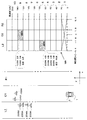
また、下記に記載の数式や図3に示すFM−CW信号とビート信号についての各記号は以下に示すものである。fb:ビート周波数、fs:周波数、fr:距離周波数、fup:アップ区間の距離周波数、fdn:ダウン区間の距離周波数、fd:速度周波数、fo:送信波の中心周波数、△f:周波数偏移幅、fm:変調波の繰り返し周波数、C:光速(電波の速度)、T:物体までの電波の往復時間、R:物体までの距離、V:物体との相対速度、S:横位置。 Moreover, each symbol about the numerical formula described below and the FM-CW signal and beat signal shown in FIG. 3 is shown below. f b : beat frequency, fs: frequency, f r : distance frequency, f up : distance frequency in up section, f dn : distance frequency in down section, f d : velocity frequency, f o : center frequency of transmission wave, Δ f: frequency deviation width, f m : repetition frequency of the modulated wave, C: speed of light (radio wave velocity), T: round-trip time of radio wave to the object, R: distance to the object, V: relative velocity with the object, S: Horizontal position.
図3上図はFM−CWの送信信号および受信信号の信号波形を示す図である。また、図3下図は送信信号と受信信号との差分周波数により生じるビート周波数を示す図である。図3上図は横軸は時間、縦軸は周波数を示している。図中、実線で示す送信信号は、所定周期で周波数が変わる性質を有しており、周波数が上昇するアップ区間と、所定の周波数まで上昇した後に所定の周波数まで下降するダウン区間がある。そして、送信信号は、所定の周波数まで下降した後に再度所定の周波数まで上昇をするように一定の変化を繰り返す。また、送信信号は物体にあたって反射した後に受信され、同図の破線で示すような受信信号となる。受信信号についても送信信号と同じようにアップ区間とダウン区間が存在する。なお、本実施形態で用いられる周波数帯の例としては76Ghz帯の周波数があげられる。 The upper part of FIG. 3 is a diagram showing signal waveforms of FM-CW transmission signals and reception signals. Further, the lower diagram in FIG. 3 is a diagram showing the beat frequency generated by the difference frequency between the transmission signal and the reception signal. In the upper diagram of FIG. 3, the horizontal axis indicates time, and the vertical axis indicates frequency. In the figure, the transmission signal indicated by a solid line has a property that the frequency changes at a predetermined cycle, and includes an up section in which the frequency increases and a down section in which the frequency increases to a predetermined frequency and then decreases to the predetermined frequency. Then, the transmission signal repeats a certain change so as to rise to a predetermined frequency after falling to a predetermined frequency. Further, the transmission signal is received after being reflected by the object, and becomes a reception signal as indicated by a broken line in FIG. The received signal has an up period and a down period as in the case of the transmitted signal. An example of the frequency band used in the present embodiment is a frequency in the 76 Ghz band.
また、車両1と物体との距離に応じて、送信信号に比べて受信信号に時間的な遅れ(T=2R/C)が生じる。さらに、車両1と物体との間に速度差を有する場合は、送信信号に比べて受信信号が周波数fsの軸に平行にシフトする。このドップラーシフト分がfdとなる。
Further, depending on the distance between the
図3下図は横軸を時間、縦軸をビート周波数として、数1に基づいてビート周波数を算出するものである。
The lower diagram of FIG. 3 calculates the beat frequency based on
![]()
![]()
<2−2.物体検出処理>
図4は物体検出処理のフローチャートである。送信信号と受信信号とをミキシングすることにより生じるビート信号をA/D変換部(Analog to Digital Converter)18によりA/D変換して、信号処理部11に取り込み、信号処理部11によりビート信号にFFT(Fast Fourier Transform 高速フーリエ変換)処理を施す(ステップS101)。
<2-2. Object detection processing>
FIG. 4 is a flowchart of the object detection process. A beat signal generated by mixing the transmission signal and the reception signal is A / D converted by an A / D converter (Analog to Digital Converter) 18, taken into the
FFT処理を施されたビート信号は周波数スペクトルとして検出される。一般に物体の周波数スペクトルは、相対的にノイズなどの周波数スペクトルよりもパワーレベルが大きいので、所定のパワーレベルに設けられている閾値を超えた周波数スペクトルをピーク信号として抽出する(ステップS102)。 The beat signal subjected to the FFT process is detected as a frequency spectrum. In general, since the frequency spectrum of an object has a relatively higher power level than a frequency spectrum such as noise, a frequency spectrum exceeding a threshold provided at a predetermined power level is extracted as a peak signal (step S102).
次に、アンテナの角度ごとに抽出されたピーク信号について車両1の速度、ピーク信号の信号強度、および、ピーク信号の角度の情報に基づいて、複数のピーク信号が1つのグループとしてグルーピングされる(ステップS103)。その結果、1または複数のピーク信号を含んだ複数のグループがアップ区間とダウン区間のそれぞれに生成される。ここで、グルーピング処理は物体の所定の反射範囲から受信した受信信号が、反射範囲を構成する角度ごとのピーク信号として検出され、この角度ごとのピーク信号で構成される1グループを1つの反射点の検出点として処理するものである。
Next, a plurality of peak signals are grouped as one group based on the information on the speed of the
そして、ステップS104ではアップ区間に生成された複数のグループと、ダウン区間に生成された複数のグループとのピーク信号同士をステップS105の処理でペアリングする対象のうち、静止物の検知点を構成するピーク信号の位置を車両1の周辺領域に相当するマップにおける複数の領域のいずれかに分類するピーク信号分類処理を行う(ステップS104)。 In step S104, a stationary object detection point is configured among the targets to be paired in the processing of step S105 between the peak signals of the plurality of groups generated in the up section and the plurality of groups generated in the down section. Peak signal classification processing is performed for classifying the position of the peak signal to be classified into any of a plurality of regions in the map corresponding to the peripheral region of the vehicle 1 (step S104).
ここで、静止物の検知点とは、たとえば車両1が40km/hで対象の物体に接近した場合、車両1からみればその物体が40km/hの速度で接近してきているようにみえる静止物の検知点であり、時間の経過による位置の変化が伴わない検知点である。
Here, the stationary object detection point is, for example, a stationary object in which, when the
なお、ステップS104の静止物ピークマップ生成の詳細な説明については、後に図5から図8の図面を用いて詳細に説明する。 The detailed description of the stationary object peak map generation in step S104 will be described later in detail with reference to FIGS.
図4のステップS104の処理の後、ステップS105のペアリング処理を行う。このペアリング処理は、アップ区間に生成された複数のグループと、ダウン区間に生成された複数のグループのピーク信号同士を、車両1の速度、グルーピングされたピーク信号の信号強度、および、グルーピングされた信号の角度の情報に基づいて組み合わせる処理である(ステップS105)。このペアリング処理により、物体からの相対距離、相対速度、および、角度のパラメータを有した検知点が検出される。
After the process of step S104 in FIG. 4, the pairing process of step S105 is performed. In this pairing process, the peak signals of the plurality of groups generated in the up section and the plurality of groups generated in the down section are grouped into the speed of the
そして、直近の物体検出処理において検出された検知点である現在検知点が過去の物体検出処理において検出された過去検知点とが連続した検知点であり、検知点が連続的に検出されているか否かを導出する連続性判定処理を行う(ステップS106)。なお、このステップS106の連続性判定の処理については、図9および図10を用いて詳細に説明する。 Whether the current detection point, which is the detection point detected in the most recent object detection process, is a detection point in which the past detection point detected in the past object detection process is continuous, and the detection point is continuously detected. A continuity determination process for deriving whether or not is performed (step S106). The continuity determination process in step S106 will be described in detail with reference to FIGS.
連続性判定の結果、検知点が連続的に検出されたか否かに応じて、その値が加算または減算されるカウンタ値を対応した検知点データとともにメモリ11bに記録する(ステップS107)。そして、対象の検知点が連続して3回以上検出されている場合(連続性2回以上の場合)(ステップS108がYes)はステップS110に進み、対象の検知点のカウンタ値がデータ出力閾値以上か否かを導出する(ステップS110)。
As a result of the continuity determination, the counter value to which the value is added or subtracted is recorded in the
ステップS108に戻って、検知点が初めて検出された新規の検知点の場合(連続性0回の場合)、または、前回初めて検出されて、今回も検出された検知点の場合(連続性1回の場合)(ステップS108がNo)は、検知点が移動物の検知点か否かを導出する(ステップS109)。 Returning to step S108, when the detection point is a new detection point detected for the first time (when continuity is zero), or when the detection point is detected for the first time last time and this time is also detected (continuity once). In the case of (No in step S108), it is derived whether or not the detection point is a detection point of a moving object (step S109).
移動物の検知点か否かは、検出された検知点の車両1との相対速度で判定でき、移動物の検知点でない場合(静止物の検知点の場合)(ステップS109がNo)は、車両1のACCがOFF状態か否かを導出して(ステップS116)、車両1のACCがOFF状態の場合(ステップS116がYes)は、処理を終了する。また、車両1のACCがOFF状態でない場合(ステップS116がNo)は、ステップS101の処理へ戻り、走査による検知点の検出を行う。
Whether or not it is a moving object detection point can be determined by the relative speed of the detected detection point with respect to the
次にステップS109に戻って、検知点が移動物の検知点の場合(ステップS109がYes)は、ペアリング正誤判定(ステップS115)の処理を行う。 Next, returning to step S109, when the detection point is the detection point of the moving object (step S109 is Yes), the pairing correct / incorrect determination (step S115) is performed.
ステップS115のペアリング正誤判定処理では、上記のように移動物の検知点を判定の対象としている。ここで、移動物の検知点とは、ステップS105までの処理で検出された検知点のうち、たとえば車両1が40km/hで対象の物体に接近した場合、車両1からみればその検知点が70km/hの速度で接近してきているようにみえる(物体は車両1に30km/hの速度で車両1の方向に向かって走行している)移動物の検知点であり、時間の経過により位置が変化する検知点である。
In the pairing correctness determination process in step S115, the detection point of the moving object is set as the determination target as described above. Here, the detection point of the moving object is, for example, when the
なお、移動物の検知点は車両1の方向に向かってくる対向車の検知点と、車両1の走行方向と同じ方向に走行する先行車の検知点とに分けられるが、車両1が移動物の検知点として検出した場合に、誤った制御を行うことを防止する観点から以下では、車両1の方向に向かってくる対向車の検知点について説明を行うが、対向車の検知点に限定されず先行車の検知点についても適用可能である。
The detection point of the moving object is divided into the detection point of the oncoming vehicle that faces in the direction of the
このようにステップS115のペアリング正誤判定では、移動物の検知点の位置がステップS104でピーク信号を分類したマップの複数の領域のうち分類された静止物データを構成するピーク信号の数が所定の閾値以上となる領域内に該当した場合は、移動物の検知点をピーク信号の組み合わせを誤ったペアリングで検出された可能性のある検知点である特定検知点として導出する。なお、この判定の詳細な説明は後に図11および図12の図面を用いて詳細に説明する。 As described above, in the pairing correctness determination in step S115, the number of peak signals constituting the stationary object data classified among the plurality of regions of the map in which the position of the moving object detection point is classified in step S104 is predetermined. If it falls within a region that is greater than or equal to the threshold value, the detection point of the moving object is derived as a specific detection point that is a detection point that may be detected by incorrect pairing of a combination of peak signals. A detailed description of this determination will be described later in detail with reference to FIGS. 11 and 12.
ステップS115の処理の後、車両1がACC−OFF状態か否かを導出して(ステップS116)、車両1がACC−OFF状態の場合(ステップS116がYes)は、処理を終了する。また、車両1のACCがOFF状態でない場合(ステップS116がNo)は、ステップS101の処理へ戻り、走査による検知点の検出を行う。
After the process of step S115, it is derived whether or not the
ステップS110に戻って、現在検知点のカウンタ値がデータ出力閾値以上の場合は、次に検知点結合処理を行う(ステップS111)。この検知点結合処理は、1つの物体の1つの反射点である検知点を1または複数組み合わせて1つの物体データとする処理である。具体的には乗用車、トラック、および、バイクなどの移動物やガードレールや鉄橋およびガードレールなどの静止物の1つの物体からの1または複数の反射点に基づく検知点を1つの物体データとして結合する処理である。 Returning to step S110, if the counter value of the current detection point is greater than or equal to the data output threshold value, then the detection point combining process is performed (step S111). This detection point combining process is a process of combining one or a plurality of detection points which are one reflection point of one object into one object data. Specifically, processing for combining detection points based on one or a plurality of reflection points from one object of a moving object such as a passenger car, a truck, and a motorcycle, or a stationary object such as a guard rail, an iron bridge, and a guard rail as one object data It is.
この物体データは車両制御部3に出力される(ステップS112)。出力された物体データに基づき、車両制御部3はブレーキ40の操作、スロットル41の操作、および、警報器42の操作など各車両制御部を用いて車両1を制御をする。
This object data is output to the vehicle control unit 3 (step S112). Based on the output object data, the
そして、車両1がACC−OFF状態の場合(ステップS113がYes)は処理を終了し、車両1がACC−ON状態の場合(ステップS113がNo)は、ステップS101に戻って新たな物体検出処理を繰り返し行う。
Then, when the
またステップS110に戻って過去検知点のカウンタ値がデータ出力閾値以上ではない場合(ステップS110がNo)は、カウンタ値がデータ出力閾値未満の過去検知点のデータをメモリ11bから削除して(ステップS114)処理を終了する。
Returning to step S110, if the counter value of the past detection point is not equal to or greater than the data output threshold (No in step S110), the data of the past detection point whose counter value is less than the data output threshold is deleted from the
<2−3静止物ピークマップ生成処理>
次に、図4のステップS104の静止物ピークマップ生成の処理について図5から図8を用いて詳細に説明する。図5はピーク信号分類処理のフローチャートである。処理の説明の前に検出される物体について、図6の検知点検出の具体例を示す図を用いて説明する。
<2-3 stationary object peak map generation processing>
Next, the stationary object peak map generation process in step S104 in FIG. 4 will be described in detail with reference to FIGS. FIG. 5 is a flowchart of the peak signal classification process. An object detected before the description of the process will be described with reference to a specific example of detection point detection in FIG.
なお、図6以降に示すxy座標軸は車両1に対して相対的に固定され、車両1の横方向(左右方向)がx軸方向、縦方向(進行方向)がy軸方向に対応する。
The xy coordinate axes shown in FIG. 6 and subsequent figures are fixed relative to the
図6では、道路C1上で+y方向を進行方向とする車両1に備えられたレーダ装置2の走査範囲RE内に、静止物A1(鉄橋)、および、静止物A2(ガードレール)を検出していることを示している。そして、レーダ装置2は道路C1上で車両1の進行方向(+y方向)に位置する静止物A1について複数の検知点である検知点101、検知点102、検知点103、および、検知点104を検出している。また、レーダ装置2は静止物A2を車両の左方向(−x方向)の道路L1上に検出しており、この静止物A2については複数の検知点である検知点201、検知点202、検知点203、検知点204、および、検知点205を検出している。
In FIG. 6, a stationary object A1 (iron bridge) and a stationary object A2 (guardrail) are detected within the scanning range RE of the
なお、以下に説明するように、静止物Aについては検知点101および検知点102は本来、静止物の検知点であるが、ペアリングを誤って移動物の検知点(車両1の方向に向かって進行する対向車の検知点で以下、「対向車の検知点」ともいう。)として検出されている。静止物Aの残りの検知点である検知点103および検知点104については静止物の検知点として検出されている。
As will be described below, for the stationary object A, the
また、静止物A2については、検知点201および検知点202は静止物の検知点であるが、ペアリングを誤って対向車の検知点として検出されている。静止物A2の残りの検知点である検知点203、検知点204、および、検知点205は静止物の検知点として検出されている。このようなペアリングの誤りは、ピーク信号の複数のグループがそれぞれ近接した位置に存在する場合に発生しやすい。
For the stationary object A2, the
図5の静止物ピークマップ生成処理では、まず最初に静止物グループの抽出を行い(ステップS201)、アップ区間およびダウン区間のそれぞれに対応するピーク信号を検出する。このステップS201およびステップS202の処理について図7を用いて説明する。図7はアップ区間とダウン区間のピーク信号グループを示す図である。走査範囲RE1はアップ区間で検出されたピーク信号グループを表し、走査範囲RE2はダウン区間で検出されたピーク信号グループを表している。そして、静止物A1を構成している検知点101はそのピーク信号の信号強度と角度の情報からピークグループ101Uとピークグループ101Dとがペアリングされて静止物の検知点として検出されるはずが、複数のピークグループ(以下、単に「グループ」という。)が近接した位置に存在するため、誤ってグループ101Uとグループ102Dとがペアリングされる(PA1)ことになっており、ペアリングされれば対向車の検知点となる。
In the stationary object peak map generation process of FIG. 5, first, a stationary object group is extracted (step S201), and peak signals corresponding to the up and down sections are detected. The processing of step S201 and step S202 will be described with reference to FIG. FIG. 7 is a diagram showing peak signal groups in the up section and the down section. The scanning range RE1 represents a peak signal group detected in the up section, and the scanning range RE2 represents a peak signal group detected in the down section. The
また、検知点102は検知点101と同様にピーク信号の信号強度と角度の情報からグループ102Uとグループ102Dとがペアリングされて静止物の検知点としてはずが、グループ102Uとグループ101Dとがペアリングされる(PA2)ことになっており、ペアリングされれば対向車の検知点となる。
Similarly to the
なお、その他のグループ103Uおよびグループ103Dと、グループ104Uおよびグループ104Dとはそれぞれ適正にペアリングされることになっており、ペアリングされれば静止物の検知点となる。
The
静止物A2を構成している検知点201はそのピーク信号の信号強度と角度の情報からグループ201Uとグループ201Dとがペアリングされて静止物の検知点として検出されるはずが、複数のグループが近接した位置に存在するため、誤ってグループ201Uとグループ202Dとがペアリングされる(PA3)ことになっており、ペアリングされれば対向車の検知点となる。
The
また、検知点202はそのピーク信号の信号強度と角度の情報からグループ202Uとグループ202Dとがペアリングされて静止物の検知点として検出されるはずが、複数のグループが近接した位置に存在するため、誤ってグループ202Uとグループ201Dとがペアリングされる(PA4)ことになっており、ペアリングされれば対向車の検知点として検出となる。
The
なお、その他のグループ203Uおよびグループ203Dと、グループ204Uおよびグループ204Dと、グループ205Uおよびグループ205Dとはそれぞれ適正にペアリングされることになっており、ペアリングされれば静止物の検知点となる。
The
したがって、図5のステップS201の静止物グループ抽出の処理では、アップ区間のグループではグループ103U、104U、203U、204U、205Uが抽出され、ダウン区間のグループではグループ103D、104D、203D、204D、205Dとが抽出される。
Therefore, in the stationary object group extraction process in step S201 of FIG. 5, the
そして、アップ区間およびダウン区間のグループのそれぞれに対応するピーク信号が検出される。ステップS202以下の処理について図8を用いて説明する。図8は、静止物の検知点を構成するピーク信号のマップMAへの適用図である。図7の処理で検出された静止物の検知点を構成するグループ103Uおよびグループ103Dと、グループ104Uおよびグループ104Dと、グループ203Uおよびグループ203Dと、グループ204Uおよびグループ204Dと、グループ205Uおよびグループ205Dとのデータから、図8に示すグループ103M、グループ104M、グループ203M、グループ204M、グループ205M、および、グループ206Mの各グループのピーク信号を検出する。
And the peak signal corresponding to each of the group of an up area and a down area is detected. The processing after step S202 will be described with reference to FIG. FIG. 8 is an application diagram of the peak signal constituting the stationary object detection point to the map MA. The
ここで、たとえばグループ103Mはグループ103Uおよびグループ103Dに基づいて抽出されたグループである。グループ103Uを構成しているピーク信号とグループ103Dを構成しているピーク信号のうちピーク信号強度と角度の情報から、アップ区間とダウン区間のそれぞれに対応するピーク信号が存在するピーク信号のみを抽出して、グループ103Mを抽出する。つまり、グループ103Uのピーク信号は3本で、グループ103Dのピーク信号は3本であることから、それぞれのピーク信号の信号強度および角度の情報に基づいて対応するピーク信号を抽出した結果、グループ103Mはピーク信号が3本で構成されるグループとなる。
Here, for example, the
また、別のグループのグループ104Mはグループ104Uおよびグループ104Dに基づいて抽出されたグループである。グループ104Uを構成しているピーク信号とグループ104Dを構成しているピーク信号のうちピーク信号強度と角度の情報から、アップ区間とダウン区間のそれぞれに対応するピーク信号が存在するピーク信号のみを抽出して、グループ104Mを構成する。つまり、グループ104Uのピーク信号は3本で、グループ104Dのピーク信号は4本であるが、それぞれのピーク信号の信号強度および角度の情報に基づいて対応するピーク信号を抽出した結果、グループ104Mはピーク信号が3本で構成されるグループとなる。このように静止物の検知点を構成するアップ区間およびダウン区間のグループのぞれぞれに対応するピーク信号を検出する。その結果、他のグループであるグループ203Mは信号数が4本、グループ204は信号数が4本、グループ205は信号数が4本、および、グループ206は信号数が4本となる。
Another
図5のフローチャートに戻りステップS202の処理の後、全グループのピーク信号の検出が完了しているか否かを判定する(ステップS203)。全グループのピーク信号の検出が完了していれば(ステップS203がYes)ステップS204に進み、全グループのピーク信号の検出が完了していなければ(ステップS203がNo)、ステップS202の処理を繰り返し行う。本実施形態では、グループ103Uおよびグループ103Dと、グループ104Uおよびグループ104Dと、グループ203Uおよびグループ203Dと、グループ204Uおよびグループ204Dと、グループ205Uおよびグループ205Dとのデータの全てのグループのピーク信号の検出が完了しているか否かを判定して、それぞれの処理へ進む。
Returning to the flowchart of FIG. 5, after the process of step S202, it is determined whether or not the detection of the peak signals of all groups is completed (step S203). If the detection of the peak signals of all the groups is completed (Yes at Step S203), the process proceeds to Step S204. If the detection of the peak signals of all the groups is not completed (No at Step S203), the process of Step S202 is repeated. Do. In the present embodiment, detection of peak signals of all groups of data of
そして、図5の処理では、以下に説明するマップMAに対応して、数2を用いてピーク信号の周波数を算出する(ステップS204)。
In the process of FIG. 5, the frequency of the peak signal is calculated using
![]()
![]()
![]()
![]()
![]()
![]()
上記のピーク信号のマップへの分類処理を図8の静止物の検知点を構成するピーク信号のマップMAへの分類図を用いて具体的に説明する。図8に示すマップMAは、車両1の周辺領域に相当するもので複数の領域に分類されている。このマップMAは縦軸と横軸の二方向で形成されており、マップMAの縦軸(y軸方向)は周波数を示している。車両1のレーダ装置2が備えられた位置付近が0kHzとなっており、車両1の進行方向(+y方向)に進むにしたがって周波数が増加しており、20kHzごとに区分されている。なお、周波数は縦方向(y軸方向)の距離に相当する。
The above-described classification processing of the peak signal into the map will be specifically described with reference to the classification diagram of the peak signal constituting the stationary object detection point in FIG. 8 into the map MA. The map MA shown in FIG. 8 corresponds to the peripheral area of the
また、マップMAの横軸(x軸方向)は横方向の距離を示し、車両1の位置が原点となり、その左右方向(x軸方向)を車両1の位置を基準とした検知点の位置を横位置として規定している。そして、マップMAはこのような縦横の区分により複数の領域に分類されており、これにより領域ごとに移動物のデータを構成する検知点のペアリング処理の正誤を確認できる。
The horizontal axis (x-axis direction) of the map MA indicates the distance in the horizontal direction, the position of the
そして、上記図5のステップS203で検出された静止物の検知点を構成するピーク信号をその周波数と横位置に応じてマップMAの該当区分に分類する。車両1と同じ道路C1上に位置するグループ103およびグループ104の各ピーク信号は、その周波数と横位置からマップMAの縦軸は周波数の区間9(160kHzから180kHz)に該当し、横軸は車両1の道路C1と対応する位置および幅を有する区間C2(−1.8mから+1.8m)に該当する。したがって、グループ103およびグループ104のピーク信号はマップMAの領域MA1に該当し、この領域MA1のピーク信号の本数の合計は6本となる。
And the peak signal which comprises the detection point of the stationary object detected by step S203 of the said FIG. 5 is classified into the applicable division of map MA according to the frequency and a horizontal position. Each peak signal of the
次に、車両1の左方向(−x方向)の道路L1上に位置するグループ203、グループ204、グループ205、および、グループ206の各ピーク信号は、その周波数と横位置からマップMAの縦軸は周波数の区間5に(80kHzから100kHz)に該当し、横軸は車両1左方向(−x方向)の道路L1に対応する位置および幅を有する区間L2(−1.8mから−5.4m)に該当する。したがって、グループ203、グループ204、グループ205、および、グループ206の各ピーク信号はマップMAの領域MA2に該当し、この領域MA2のピーク信号の本数の合計は16本となる。このように分類されたピーク信号のマップMAのデータは信号処理部11のメモリ11bに保存される。
<2−4.連続性判定処理>
次に、図4に示したステップS106の連続性判定処理について、図9の連続性判定処理フローチャートを用いて詳細に説明する。この連続性判定の主な処理は、直近の物体検出処理により検出された現在検知点と過去に検出された過去検知点との連続性を判定し、連続性がある検知点はカウンタ値を加算し、連続性のない検知点はカウンタ値を減算する処理である。
Next, the peak signals of the
<2-4. Continuity judgment processing>
Next, the continuity determination process of step S106 shown in FIG. 4 will be described in detail using the continuity determination process flowchart of FIG. The main process of this continuity determination is to determine the continuity between the current detection point detected by the most recent object detection process and the past detection point detected in the past, and the counter value is added to the detection point with continuity. The detection point having no continuity is a process of subtracting the counter value.
物体検出処理により検出された現在検知点と過去検知点との連続性が0回の場合(ステップS301がYes)、詳細には直近の物体検出処理で初めて検出された検知点の場合は処理を終了し、カウンタ101aによる過去検知点に対するカウンタ値の加減算は行わない。なお、図9の処理が終了した後に図4に示したステップS107の処理で検知点のデータとカウンタ値(この場合はカウンタ値0)をメモリ11bに記録する。以下、図9の各処理でもカウンタ値の増減に伴い検知点のデータとカウンタ値をメモリ11bに記録する。。
If the continuity between the current detection point detected by the object detection process and the past detection point is zero (step S301: Yes), in particular, if the detection point is detected for the first time in the latest object detection process, the process is performed. The counter value is not added to or subtracted from the past detection point by the
図9に戻って、検知点の連続性が0回ではない場合(ステップS301がNo)で、現在検知点と過去検知点との連続性が1回の場合(ステップS302がYes)は、カウンタ101aにより過去検知点のカウンタ値に5の値を加算して(ステップS303)処理を終了する。 Returning to FIG. 9, when the continuity of the detection points is not zero (step S301 is No) and the continuity between the current detection point and the past detection point is one (step S302 is Yes), the counter The value of 5 is added to the counter value of the past detection point by 101a (step S303), and the process is terminated.
検知点の検出の連続性が1回ではない場合(ステップS302がNo)は、現在検知点と過去検知点との検出の連続性が2回であるか否かを導出し(ステップS304)、検知点の検出の連続性が2回の場合(ステップS304がYes)は、カウンタ101aにより検知点のカウンタ値に5の値を加算して(ステップS305)処理を終了する。
When the detection continuity of the detection point is not once (No in step S302), it is derived whether or not the detection continuity of the current detection point and the past detection point is two times (step S304). When the detection point detection continuity is twice (Yes in step S304), the
なお、後に図10を用いて説明するように、カウンタ値が10の位置をデータ出力閾値A1(以下、「閾値A1」ともいう。)とし、過去検知点のカウンタに値を加算した現在検知点のカウンタの値が閾値A1の値である10以上となると、信号処理部11は閾値A1を以上のカウンタ値の検知点で構成される物体データが車両制御部3に出力する。
As will be described later with reference to FIG. 10, the position where the counter value is 10 is defined as the data output threshold A1 (hereinafter also referred to as “threshold A1”), and the current detection point obtained by adding the value to the counter of the past detection points. When the value of the counter becomes 10 or more, which is the value of the threshold A1, the
現在検知点と過去検知点との検出の連続性が2回ではない場合(ステップS304がNo)は、検知点の検出の連続性が3回であるか否かを導出し(ステップS306)、連続性が3回の場合(ステップS306がYes)は、カウンタ101aにより過去検知点のカウンタ値に2の値を加算して(ステップS307)処理を終了する。
When the continuity of detection of the current detection point and the past detection point is not twice (No in step S304), it is derived whether the continuity of detection of the detection point is three times (step S306). When the continuity is three times (step S306 is Yes), the
検知点の検出の連続性が3回ではない場合(ステップS306がNo)、前回検出した検知点を今回の走査で検出しているか否かを導出する(ステップS308)。前回検出した検知点を今回の走査で検出している場合(ステップS308がYes)は、過去検知点のカウンタ値に2の値を加算する(ステップS309)。なお、過去検知点にカウンタの値を加算した結果の値については、所定の上限値が設けられており、例えばカウンタ値が14を超えるとそれ以上カウンタの値は上昇しない。 If the detection point detection continuity is not three times (No in step S306), it is derived whether or not the previously detected detection point is detected in the current scan (step S308). When the previously detected detection point is detected in the current scan (Yes in step S308), a value of 2 is added to the counter value of the past detection point (step S309). Note that a predetermined upper limit is provided for the value obtained by adding the counter value to the past detection point. For example, when the counter value exceeds 14, the counter value does not increase any more.
前回の走査で検出した検知点が今回の走査で検出されていない場合(ステップS308がNo)、つまり過去検知点と連続性のある現在検知点が存在しない場合は、連続性が確認できない過去検知点をメモリ11bから読み出して(ステップS310)、検知点が静止物を対象としたものか移動物を対象としたものかなどの検知点の種類に応じてカウンタ値を減算する。
If the detection point detected in the previous scan is not detected in the current scan (No in step S308), that is, if there is no current detection point that is continuous with the past detection point, past detection in which continuity cannot be confirmed The point is read from the
連続性が確認できない検知点のカウンタ値が1回以上閾値A1以上となった過去検知点(1度でもカウンタの値が10以上となった過去検知点)の場合(ステップS311がYes)は、外挿処理を行う。 In the case of a past detection point where the counter value of the detection point for which continuity cannot be confirmed is equal to or greater than the threshold A1 at least once (a past detection point where the counter value is 10 or more even once) (Yes in step S311), Perform extrapolation.
ここで、外挿処理とは過去検知点のカウンタ値が1回以上閾値A1以上となった過去検知点の連続性が確認できない場合に、所定の位置に検知点が存在するものとして過去検知点のデータを更新し、カウンタ値は減算する処理であり、更新された検知点(現在検知点)のデータと減算されたカウンタ値がメモリ11bに記録される。
Here, extrapolation processing refers to a case where a detection point exists at a predetermined position when the continuity of the past detection point whose past detection point counter value has reached the threshold value A1 or more cannot be confirmed. Is updated, and the counter value is subtracted. The updated detection point (current detection point) data and the subtracted counter value are recorded in the
そして、カウンタ値が1回以上閾値A1以上となった過去検知点における外挿処理は、その処理回数が1回の場合に減算されたカウンタ値によりすぐにメモリ11bから対象の過去検知点のデータを削除することはなく、複数回の外挿処理に伴うカウンタ値の減算により過去検知点のカウンタの値が閾値A1よりも値が低いデータ削除閾値B1(以下、「閾値B1」ともいう。)を下回った場合にメモリ11bから対象の過去検知点のデータを削除する。これにより、存在の可能性が高い過去検知点の連続性が確認できない場合でもすぐにはメモリ11bから削除せずに、複数回の物体検出処理の中でその存在可能性を判断できる。
Then, the extrapolation process at the past detection point whose counter value is equal to or greater than the threshold value A1 is performed immediately from the
図9の説明に戻り、ステップS311で検知点がカウンタ値が1回以上閾値A1以上となった検知点ではない場合(ステップS311がNo)は、対象の過去データをメモリ11bから削除して(ステップS312)処理を終了する。これにより、存在の可能性の低い過去検知点は早期にメモリ11bから削除して、他の存在可能性の高い過去検知点を優先的に記録すことができる。
Returning to the description of FIG. 9, when the detection point is not a detection point whose counter value has reached the threshold value A1 or more in step S311 (No in step S311), the target past data is deleted from the
次にステップS311がYesの場合の後の処理は、各検知点の種類に応じてカウンタ値を減算する処理を行う。メモリ11bから読み出した検知点が静止物の検知点の場合(ステップS313がYes)は、対象の過去検知点のカウンタ値を2減算して(ステップS314)処理を終了する。
Next, the process after step S311 is Yes performs the process which subtracts a counter value according to the kind of each detection point. When the detection point read from the
検知点が静止物でない場合(ステップS313がNo)は、検知点が対向車か否かを導出する(ステップS315)。検知点が対向車か否かは過去の検知点データと比較して車両1に接近しているか否かを導出する。そして、検知点が対向車の場合(ステップS315がYes)、その検知点がミスペアリングの可能性のある特定検知点の場合(ステップS317がYes)、正常にペアリングが行われた一般検知点の減算値よりも大きい減算値となるカウンタ値を3減算して(ステップS318)処理を終了する。
If the detection point is not a stationary object (No in step S313), it is derived whether or not the detection point is an oncoming vehicle (step S315). Whether or not the detection point is an oncoming vehicle is derived from whether or not the vehicle is approaching the
なお、対向車の検知点が特定検知点ではない一般検知点の場合(ステップS317がNo)は、特定検知点よりも減算値の少ないカウンタ値を2減算して(ステップS319)処理を終了する。 If the detection point of the oncoming vehicle is a general detection point that is not a specific detection point (No in step S317), the counter value having a smaller subtraction value than that of the specific detection point is subtracted by 2 (step S319), and the process ends. .
ステップS315に戻って、検知点が対向車ではない場合(ステップS315がNo)、つまり検知点が先行車の場合は、カウンタ値を2減算して(ステップS316)処理を終了する。 Returning to step S315, if the detection point is not an oncoming vehicle (No in step S315), that is, if the detection point is a preceding vehicle, the counter value is subtracted by 2 (step S316) and the process is terminated.
なお、これらのカウンタの値の加算および減算の値や、閾値A1および閾値B1の値は一例であり、他の値に変更してもよいが、特定検知点のカウンタ値の減算値は他の検知点の減算値よりも大きい値であり、閾値A1の値は閾値B1の値よりも大きい値となる。 Note that the addition and subtraction values of these counter values and the values of the threshold value A1 and the threshold value B1 are examples, and may be changed to other values. However, the subtraction value of the counter value at the specific detection point may be other values. The value is larger than the subtraction value of the detection point, and the value of the threshold A1 is larger than the value of the threshold B1.
図10は、検知点のカウンタ値の推移を示す図である。図10に示すグラフは縦軸がカウンタ値となっており、上限の値が14となっている。また、横軸は1目盛りが物体検出処理の1サイクルの時間に対応した時間となっている。なお、本実施の形態では1サイクルを150msとしている。 FIG. 10 is a diagram illustrating the transition of the counter value at the detection point. In the graph shown in FIG. 10, the vertical axis is the counter value, and the upper limit value is 14. On the horizontal axis, one scale corresponds to a time corresponding to one cycle of the object detection process. In this embodiment, one cycle is 150 ms.
図10のT1の物体検出処理では物体検出処理により検知点R1が検出されており、信号処理部11はメモリ11bに検知点R1のデータと検知点R1のカウンタ値0を記録する処理を行う。そして、次のT2の物体検出処理では直近の150ms(1サイクル前)の物体検出処理で検出された検知点R1を過去検知点とした場合に連続性のある現在検知点R2が検出されている。この現在検知点R2の検出により過去検知点R1のカウンタ値が5加算され、検知点R2のデータとカウンタ値が0から5に更新され、メモリ11bに記録される。
In the object detection process of T1 in FIG. 10, the detection point R1 is detected by the object detection process, and the
T3の物体検出処理では、検知点R2を過去検知点とした場合に連続性を有する現在検知点は存在せず、新たに検出された検知点S1が存在している。そのため、信号処理部11はメモリ11bの過去検知点R2のデータとカウンタ値をメモリ11bから削除し、新規に検出された検知点S1のデータとカウンタ値0を記録する。
In the object detection process of T3, when the detection point R2 is a past detection point, there is no current detection point having continuity, and there is a newly detected detection point S1. Therefore, the
次に、T4の物体検出処理では、検知点S1を過去検知点とした場合に連続性を有する現在検知点S2が検出されている。そのため、信号処理部11は過去検知点S1のカウンタの値0に5を加算して、現在検知点S2のデータとカウンタ値5をメモリ11bに記録する。
Next, in the object detection process at T4, the current detection point S2 having continuity is detected when the detection point S1 is a past detection point. Therefore, the
T5の物体検出処理では、検知点S2を過去検知点とした場合に連続性を有する現在検知点S3が検出されている。そのため信号処理部11は、過去検知点S2のカウンタ値5に5の値を加算して、現在検知点S3のデータとカウンタ値10をメモリ11bに記録する。なお、現在検知点S3のカウンタ値は車両制御部3に検知点の情報を用いて構成される物体データを出力する閾値A1以上となっているため、現在検知点S3は物体データを構成する要素となり、車両制御部3へ出力される。
In the object detection process at T5, the current detection point S3 having continuity is detected when the detection point S2 is a past detection point. Therefore, the
T6およびT7の物体検出処理では過去検知点S3が継続して検出されているため、T6では現在検知点がS4となり、検知点S4のデータとカウンタ値10に2を加算したカウンタ値12がメモリ11bに記録される。また、T7では過去検知点S4に対して検知点S5が現在検知点となり、検知点S5のデータとカウンタの値12に2を加算したカウンタ値14がメモリ11bに記録される。
Since the past detection point S3 is continuously detected in the object detection processing at T6 and T7, the current detection point is S4 at T6, and the
検知点S5のカウンタ値は上限のカウンタ値14のため、次の物体検出処理であるT8の物体検出処理では、過去検知点をS5とする現在検知点S6に連続性がある場合でも、カウンタ値は14として検知点S6のデータをメモリ11bに記録する。
Since the counter value of the detection point S5 is the upper
次に、過去検知点をS6とした場合に現在検知点との連続性が確認できないときに、所定の位置に検知点が存在するものとして仮定的に過去検知点のデータを更新する外挿処理を行い、現在検知点としてメモリ11bに記憶して検知点のデータの連続性を保つ。
Next, when the past detection point is set to S6 and the continuity with the current detection point cannot be confirmed, extrapolation processing for presumably updating the data of the past detection point on the assumption that the detection point exists at a predetermined position Is stored in the
そして、これまで説明した検知点S1からS6まで連続性を有する検知点が後述するペアリング正誤判定処理において、ピーク信号の組み合わせを誤ったペアリングで検出された可能性のある特定検知点の場合をSA7以降の検知点とし、ピーク信号の組み合わせが正しい組み合わせでペアリングされた可能性のある一般検知点の場合をSB7以降の検知点として、この後の各検知点の推移を説明する。 In the pairing correctness determination process described later, the detection points having continuity from the detection points S1 to S6 described so far are specific detection points that may have been detected by incorrect pairing of the peak signals. The transition of each detection point will be described below with the detection points after SA7 as the detection points after SB7 where the combination of peak signals may be paired with the correct combination.
T8での過去検知点S6が一般検知点の場合に、次の物体検出処理のT9で現在検知点との連続性が確認できないときは、仮想的に現在検知点SB7を導出する。このように外挿処理により仮想的に導出された現在検知点SB7のカウンタ値は元のカウンタ値から2減算され、メモリ11bには現在検知点SB7のデータとカウンタ値14から2を減算したカウンタ値12が記録される。
If the past detection point S6 at T8 is a general detection point and the continuity with the current detection point cannot be confirmed at T9 of the next object detection process, the current detection point SB7 is virtually derived. Thus, the counter value of the current detection point SB7 virtually derived by extrapolation processing is subtracted by 2 from the original counter value, and the
その後、検知点SB7を過去検知点としたT10のSB8以降の複数回の外挿処理の結果、1回の外挿処理ごとに検知点のカウンタ値を2ずつ減算して、検知点のデータとともにカウンタ値をメモリ11bに記録する。そして、T13における過去検知点をSB10とする検知点SB11のデータとカウンタ値4がメモリ11bに記録される。そして、検知点SB11はメモリ11bから検知点データを削除する閾値であるデータ削除閾値B1を下回っている。そのため、T1〜T13までメモリ11bに記録を更新してきたSB11のデータをメモリ11bから削除する。
After that, as a result of a plurality of extrapolation processes after SB8 of T10 with the detection point SB7 as a past detection point, the counter value of the detection point is subtracted by 2 for each extrapolation process, and together with the data of the detection point The counter value is recorded in the
次に、T8の物体検出処理の説明に戻り検知点S6が特定検知点の場合は、特定検知点S6を過去検知点として仮想的に導出された現在検知点SA7では、検知点SA7のデータと特定検知点S6のカウンタ値14から3の値を減算したカウンタ値11をメモリ11bに記録する。
Next, returning to the description of the object detection process at T8, when the detection point S6 is a specific detection point, the current detection point SA7 virtually derived from the specific detection point S6 as a past detection point is the data of the detection point SA7. The
その後、特定検知点SA7を過去検知点としたT10における仮想的な現在検知点SA8のデータとカウンタ値8がメモリ11bに記録される。次に、特定検知点SA8を過去検知点としたT11の仮想的な現在検知点SA9のデータとカウンタ値5がメモリ11bに記録される。
Thereafter, the data of the virtual current detection point SA8 and the
メモリ11bに記録された検知点SA9はデータ削除閾値B1を下回っていることから、検知点SA9のデータは、T11の走査でメモリ11bから削除される。つまり、一般検知点を外挿処理する場合の減算値よりも特定検知点を外挿処理する場合の減算値が大きい値であることからピーク信号の組み合わせを誤ったペアリングで検出された可能性のある特定検知点を他の検知点よりも早くメモリ11bから削除することで不適切な車両制御を防止できる。具体的には図10に示すように特定検知点はT11でメモリ11bから削除され、一般検知点はT13でメモリ11bから削除される。つまり、特定検知点は一般検知点よりも300ms(2サイクルの物体検知処理早くメモリ11bから削除される。
Since the detection point SA9 recorded in the
また、閾値A1を1回以上超えたS6を特定検知点とした場合に、特定検知点S6の連続性が確認できない場合に、特定検知点のデータが閾値B1を下回るまでメモリ11bから特定検知点のデータを削除せずに、外挿処理を行っている。つまり、特定検知点のカウンタ値が閾値B1を下回るまでの減算回数が複数回(図10では、S6のカウンタ値14から3を減算したSA7のカウンタ値12、SA7のカウンタ値12から3を減算したSA8のカウンタ値8、および、SA8のカウンタ値8から3を減算したSA9のカウンタ値5の合計3回)となるようにカウンタ値を減算して、閾値B1を下回ったカウンタ値の特定検知点を削除する。
In addition, when S6 that exceeds the threshold A1 at least once is set as the specific detection point, when the continuity of the specific detection point S6 cannot be confirmed, the specific detection point from the
これにより、特定検知点が閾値A1以上となり車両制御部3へ出力された場合は、ピーク信号の組み合わせを誤ったペアリングで検出された可能性があっても、すぐにはメモリ11bから特定検知点のデータを削除せず、ピーク信号の組み合わせが誤りか否かを複数回の処理をとおして判定することで、特定検知点のペアリングの正誤を判定できる。
As a result, when the specific detection point is equal to or greater than the threshold value A1 and is output to the
<2−5.ペアリング正誤判定処理>
次に、図4のステップS115に示すペアリング正誤判定処理について、図11および図12を用いて詳細に説明する。図11はペアリング正誤判定処理のフローチャートである。
<2-5. Pairing correctness judgment processing>
Next, the pairing correctness determination process shown in step S115 of FIG. 4 will be described in detail with reference to FIG. 11 and FIG. FIG. 11 is a flowchart of the pairing correctness determination process.
図4のステップS105のペアリング処理により検出された検知点が連続して3回以上検出されておらず(ステップS108がNo)、移動物の検知点である場合(ステップS109がYes)にこのペアリング正誤判定処理が実行され、車両1の方向に所定速度以上(たとえば10km/h以上)で近づいてきている対向車の検知点か否かを判定する(ステップS301)。
If the detection points detected by the pairing process in step S105 of FIG. 4 are not detected three or more times in succession (step S108 is No) and this is a detection point of a moving object (step S109 is Yes), this A pairing correctness determination process is executed, and it is determined whether or not it is a detection point of an oncoming vehicle approaching in the direction of the
車両1の方向に所定速度以上で近づいてきている対向車の検知点が有る場合(ステップS401がYes)は、ステップS402の処理へ進む。また、車両1の方向に所定速度以上で近づいてきている対向車の検知点が無い場合(ステップS401がNo)は、処理を終了する。
If there is an oncoming vehicle detection point approaching the
ステップS401がYesの場合、対向車の検知点の周波数を算出する(ステップS402)。そして、対向車の検知点の横位置を算出する(ステップS403)。周波数の算出は上記の数2を用いて行い、横位置の算出は上記の数3および数4を用いて行う。
When step S401 is Yes, the frequency of the oncoming vehicle detection point is calculated (step S402). Then, the lateral position of the detection point of the oncoming vehicle is calculated (step S403). The frequency is calculated using the
次に、ステップS402とステップS403とで算出した検知点の周波数および横位置のデータを用いて、対向車の検知点のマップMAの該当領域を算出する(ステップS404)。 Next, the corresponding area of the oncoming vehicle detection point map MA is calculated using the detection point frequency and lateral position data calculated in step S402 and step S403 (step S404).
対向車の検知点のマップMAの位置が、マップの複数の領域のうちの分類された静止物の検知点を構成するピーク信号が所定の閾値以上となる領域内に該当した場合(ステップS405がYes)は、特定検知点として判定してフラグをオンする(ステップS406)。この特定検知点として判定された対向車の検知点は、ペアリング処理の対象を誤った可能性の高い検知点となり、特定検知点とされたことは、車両制御部3の各車両制御部を制御する際の判定条件の1つとなる。
When the position of the detection point map MA of the oncoming vehicle falls within a region where the peak signal constituting the classified stationary object detection point of the plurality of regions of the map is equal to or greater than a predetermined threshold (step S405) Yes) determines as a specific detection point and turns on the flag (step S406). The detection point of the oncoming vehicle determined as the specific detection point is a detection point that is highly likely to be mistaken for the target of the pairing process, and that the specific detection point is that each vehicle control unit of the
これにより、検知点のペアリング処理の正誤を確認できる。また、新規に検出された検知点および前回初めて検出されて今回も検出された検知点に対してペアリングの正誤判定を行うことで、早期にペアリング処理の正誤を確認できる。 Thereby, the correctness of the pairing process of a detection point can be confirmed. In addition, the correctness of the pairing process can be confirmed at an early stage by performing pairing correct / incorrect determination on the newly detected detection point and the detection point detected for the first time last time and also detected this time.
なお、ステップS405において、対向車の検知点のマップMAの位置が、マップの複数の領域のうちの分類された静止物の検知点を構成するピーク信号が所定の閾値以上となる領域内に該当しない場合(ステップS405がNo)、または、特定検知点のカウントアップが行われた(ステップ406)後、全ての対向車の検知点の該当領域の分類が行われたか否かを判定する(ステップS407)。 Note that in step S405, the position of the oncoming vehicle detection point map MA corresponds to an area in which the peak signal constituting the classified stationary object detection point in the plurality of areas of the map is equal to or greater than a predetermined threshold. If not (No in step S405), or after a specific detection point is counted up (step 406), it is determined whether or not the corresponding areas of the detection points of all oncoming vehicles have been classified (step 406). S407).
全ての対向車の検知点の該当領域の分類が行われた場合(ステップS407がYes)は処理を終了する。また、全ての対向車の検知点の該当領域の分類が行われていない場合(ステップS407がNo)は、ステップS402の処理に戻る。 If the corresponding areas of the detection points of all oncoming vehicles have been classified (step S407 is Yes), the process ends. If the corresponding areas of the detection points of all oncoming vehicles have not been classified (No in step S407), the process returns to step S402.
図11の処理を図12を用いて具体的に説明する。図12は、対向車の検知点のマップへの分類を示した図である。マップMAは上記の図5および図8を用いて説明したように、静止物の検知点を構成するピーク信号を分類したマップであり、周波数の区間9、横位置の区間C2の領域MA1にグループ103Mおよびグループ104Mのピーク信号が合計6本分類され、周波数の区間5、横位置の区間L2の領域M2にグループ203M、グループ204M、グループ205M、および、グループ206のピーク信号が合計16本分類されている。
The process of FIG. 11 will be specifically described with reference to FIG. FIG. 12 is a diagram showing classification of oncoming vehicle detection points into a map. As described above with reference to FIGS. 5 and 8, the map MA is a map in which peak signals constituting stationary object detection points are classified, and is grouped into a region MA1 of a
そして領域MA1は横位置の区間がC2であり、この区間C2はピーク信号の閾値が4本で設定されている。また、領域MA2は横位置の区間がL2であり、この区間L2はピーク信号の閾値が15本で設定されている。なお、横位置の区間R2についてもピーク信号の閾値が15本で設定されている。このように左右方向(x軸方向)の各区間に設定されている閾値は、マップMAの複数の領域のうち左右方向に関して車両1と一致する領域であるC2の各領域よりも、車両1と異なる領域であるL2またはR2の領域のほうが高く設定されている。つまり、通常静止物の存在の確率の低い自車線の領域では静止物の検知点を構成するピーク信号の閾値を低く設定し、自車線以外の他の車線の領域では静止物の存在確率は自車線よりも高く、また車両1へ向かって進行してくる対向車の存在確率も高いことを考慮して、静止物の検知点を構成するピーク信号の閾値を高く設定している。
In the area MA1, the horizontal position section is C2, and the section C2 has four peak signal thresholds. In the area MA2, the section of the horizontal position is L2, and the section L2 is set with 15 peak signal thresholds. Note that the threshold value of the peak signal is set to 15 for the section R2 in the horizontal position. Thus, the threshold value set in each section in the left-right direction (x-axis direction) is greater than that in each area of C2, which is an area that matches the
このように静止物の検知点を構成するピーク信号が分類され、それぞれの領域に閾値が設定されている状態で、移動物の検知点の周波数と横位置の情報に基づいて、移動物の各検知点マップMAの各領域に分類する。図12では対向車の検知点として検出された検知点101、および、検知点102が領域MA1に分類され、同じく対向車の検知点として検出された検知点201、および、検知点202が領域MA2に分類されている。
In this manner, the peak signals constituting the detection points of the stationary object are classified, and the threshold values are set in the respective areas. It classifies into each area of detection point map MA. In FIG. 12, the
そして、領域MA1のピーク信号の閾値は4本であるところ、領域MA1の静止物の検知点を構成するピーク信号の本数は6本であるため、領域MA1に分類された対向車の検知点101および対向車の検知点102は、それぞれ特定検知点のカウンタがアップされる。
Since the threshold value of the peak signal in the area MA1 is 4, the number of peak signals constituting the stationary object detection point in the area MA1 is 6, so the
また、領域MA2のピーク信号の閾値は15本であるところ、領域MA2の静止物の検知点を構成するピーク信号の本数は16本であるため、領域MA2に分類された対向車の検知点201および対向車の検知点202は、それぞれ特定検知点のカウンタがアップされる。これにより、自車両と一致する領域(たとえば自車線の領域)と、自車両と異なる領域(たとえば自車線以外の他の車線や自車線から外れた領域)の両方で移動物を構成する検知点のペアリング処理の正誤を確認できる。
Further, since the threshold value of the peak signal in the area MA2 is 15, the number of peak signals constituting the stationary object detection point in the area MA2 is 16, so the
また、自車両と異なる領域の閾値が自車両の領域の閾値と比べて高いことから、本来対向車が存在する可能性の高い自車両と異なる領域において、対向車の検知点をペアリングを誤った対象とする可能性はない。さらに、自車両と異なる領域ではガードレールなどの静止物の検知点が存在する可能性が高いことから、閾値を高く設定していても静止物の検知点が存在する場合は、静止物の検知点を構成するピーク信号の数は閾値を上回る。 In addition, since the threshold value of the area different from the own vehicle is higher than the threshold value of the own vehicle area, pairing of the detection points of the oncoming vehicle is incorrect in an area different from the own vehicle where the oncoming vehicle is likely to exist. There is no possibility of targeting. Furthermore, since there is a high possibility that a detection point for a stationary object such as a guardrail exists in a different area from the host vehicle, if a detection point for a stationary object exists even if the threshold is set high, the detection point for a stationary object The number of peak signals constituting the number exceeds the threshold value.
なお、周波数の区間1(周波数0kHzから20kHz)は車両1と検出対象の静止物との距離が近いことから、区間L2および区間R2に位置する静止物の検知点を構成するピーク信号が区間C2に入り込んできたり、ノイズの影響を受けやすいことから、これらの区間で構成される車両1からの近傍領域は本実施形態の処理では使用しないこととしている。
In the frequency section 1 (
1・・・・・車両
2・・・・・レーダ装置
3・・・・・車両制御部
10・・・・車両制御システム
11・・・・信号処理部
12・・・・変調部
13・・・・VCO
14・・・・方向性結合器
15・・・・平面アンテナ
16・・・・ミキサ
17・・・・フィルタ
18・・・・A/D変換部
19・・・・モータ駆動部
20・・・・モータ
21・・・・エンコーダ
DESCRIPTION OF
14 ...
Claims (4)
過去の前記物体検出処理において検出された前記検知点である過去検知点を示すデータと、前記過去検知点についての存在の可能性を示すカウンタ値とを記憶する記憶手段と、
直近の前記物体検出処理において検出された前記検知点である現在検知点と前記過去検知点との連続性判定を行う判定手段と、
前記連続性判定により前記現在検知点との連続性が確認できない前記過去検知点の前記カウンタ値を減算する減算手段と、
前記カウンタ値が第1の閾値を下回った場合に、該カウンタ値に係る前記過去検知点を示すデータを前記記憶手段から削除する削除手段と、
自車両の位置に対して縦方向の所定距離と横方向の所定距離とで区分された複数の領域を有し、それぞれの領域にピーク信号の本数の閾値が設定されたマップ上のいずれかの領域に、縦方向の距離および横方向の距離に基づき分類された移動物の検知点のピーク信号の本数が、前記移動物が分類された領域の閾値を超える場合に、前記移動物の検知点を前記ピーク信号の組合せを誤ったペアリングにより検出された可能性のある誤ペアリング候補検知点として特定する特定手段と、
前記誤ペアリング候補検知点に特定された前記過去検知点の減算値を、他の前記過去検知点の減算値よりも大きい値とする変更手段と、
を備えることを特徴とする信号処理装置。
A first period and a frequency in which the frequency of the transmission signal rises as a peak signal indicating a difference frequency between a transmission signal whose frequency changes at a predetermined period and a reception signal that has received a reflected wave from an object of the transmission wave based on the transmission signal Is detected in the second period during which the object falls, and an object detection process for detecting a detection point that is a reflection point of the object related to the peak signal is performed by pairing the peak signals in the first period and the second period A signal processing device comprising:
Storage means for storing data indicating a past detection point that is the detection point detected in the past object detection processing, and a counter value indicating the possibility of existence of the past detection point;
Determination means for performing continuity determination between the current detection point and the past detection point, which are the detection points detected in the latest object detection processing;
Subtracting means for subtracting the counter value of the past detection point where continuity with the current detection point cannot be confirmed by the continuity determination;
A deletion unit that deletes data indicating the past detection point related to the counter value from the storage unit when the counter value falls below a first threshold;
One of the maps on the map that has a plurality of areas divided into a predetermined distance in the vertical direction and a predetermined distance in the horizontal direction with respect to the position of the host vehicle, and a threshold value for the number of peak signals is set in each area When the number of peak signals of moving object detection points classified in the area based on the vertical distance and the horizontal distance exceeds the threshold value of the area where the moving object is classified, the detection point of the moving object Identifying means for identifying the combination of the peak signals as an erroneous pairing candidate detection point that may have been detected by incorrect pairing ;
Changing means for setting the subtraction value of the past detection point specified as the erroneous pairing candidate detection point to a value larger than the subtraction value of the other past detection points ,
A signal processing apparatus comprising:
前記連続性判定により前記現在検知点との連続性が確認できた前記過去検知点の前記カThe past detection points that have been confirmed to be continuous with the current detection point by the continuity determination
ウンタ値を加算する加算手段と、Adding means for adding the unter value;
前記加算手段により加算されたカウンタ値が前記第1の閾値よりも値の大きい第2の閾A second threshold whose counter value added by the adding means is larger than the first threshold.
値以上の場合に、車両が備える装置を制御する車両制御装置へ前記検知点の情報を用いてWhen the value is equal to or greater than the value, the information on the detection point is used for the vehicle control device that controls the device included in the vehicle.
構成される物体データを出力する出力手段と、Output means for outputting the configured object data;
をさらに備え、Further comprising
前記減算手段は、カウンタ値が前記第2の閾値以上となった前記特定検知点の連続性がThe subtracting means determines that the continuity of the specific detection point whose counter value is equal to or greater than the second threshold value.
確認できない場合に、前記特定検知点のカウンタ値が前記第1の閾値を下回るまでの減算Subtraction until the counter value of the specific detection point falls below the first threshold value when it cannot be confirmed
回数が複数回となるようにカウンタ値を減算すること、Subtract the counter value so that the number of times is multiple times,
を特徴とする信号処理装置。A signal processing device.
前記送信波を出力し、前記反射波を受信するアンテナと、An antenna that outputs the transmitted wave and receives the reflected wave;
を備えるレーダ装置。A radar apparatus comprising:
過去の前記物体検出処理において検出された前記検知点である過去検知点を示すデータと、前記過去検知点についての存在の可能性を示すカウンタ値とを記憶する工程と、
直近の前記物体検出処理において検出された前記検知点である現在検知点と前記過去検知点との連続性判定を行う工程と、
前記連続性判定により前記現在検知点との連続性が確認できない前記過去検知点の前記カウンタ値を減算する工程と、
前記カウンタ値が第1の閾値を下回った場合に、該カウンタ値に係る前記過去検知点を示すデータを前記記憶手段から削除する工程と、
自車両の位置に対して縦方向の所定距離と横方向の所定距離とで区分された複数の領域を有し、それぞれの領域にピーク信号の本数の閾値が設定されたマップ上のいずれかの領域に、縦方向の距離および横方向の距離に基づき分類された移動物の検知点のピーク信号の本数が、前記移動物が分類された領域の閾値を超える場合に、前記移動物の検知点を前記ピーク信号の組合せを誤ったペアリングにより検出された可能性のある誤ペアリング候補検知点として特定する工程と、
前記誤ペアリング候補検知点に特定された前記過去検知点の減算値を、他の前記過去検知点の減算値よりも大きい値とする工程と、
を備えることを特徴とする信号処理方法。 A first period and a frequency in which the frequency of the transmission signal rises as a peak signal indicating a difference frequency between a transmission signal whose frequency changes at a predetermined period and a reception signal that has received a reflected wave from an object of the transmission wave based on the transmission signal Is detected in the second period during which the object falls, and an object detection process for detecting a detection point that is a reflection point of the object related to the peak signal is performed by pairing the peak signals in the first period and the second period A signal processing method comprising:
Storing data indicating a past detection point that is the detection point detected in the past object detection process, and a counter value indicating a possibility of existence of the past detection point;
Performing continuity determination between the current detection point and the past detection point, which are the detection points detected in the most recent object detection process;
Subtracting the counter value of the past detection point where continuity with the current detection point cannot be confirmed by the continuity determination;
Deleting the data indicating the past detection point related to the counter value from the storage means when the counter value falls below a first threshold;
One of the maps on the map that has a plurality of areas divided into a predetermined distance in the vertical direction and a predetermined distance in the horizontal direction with respect to the position of the host vehicle, and a threshold value for the number of peak signals is set in each area When the number of peak signals of moving object detection points classified in the area based on the vertical distance and the horizontal distance exceeds the threshold value of the area where the moving object is classified, the detection point of the moving object Identifying the combination of the peak signals as an erroneous pairing candidate detection point that may have been detected by incorrect pairing;
A step of setting the subtraction value of the past detection point specified as the erroneous pairing candidate detection point to a value larger than the subtraction value of the other past detection points;
A signal processing method comprising:
Priority Applications (4)
| Application Number | Priority Date | Filing Date | Title |
|---|---|---|---|
| JP2010148806A JP5576727B2 (en) | 2010-06-30 | 2010-06-30 | Signal processing device, radar device, vehicle control system, and signal processing method |
| DE112011102221.2T DE112011102221B4 (en) | 2010-06-30 | 2011-06-23 | Signal processing apparatus, radar apparatus, vehicle control system and signal processing method |
| US13/807,092 US9261589B2 (en) | 2010-06-30 | 2011-06-23 | Signal processing device, radar device, vehicle control system, and signal processing method |
| PCT/JP2011/064411 WO2012002251A1 (en) | 2010-06-30 | 2011-06-23 | Signal processing apparatus, radar apparatus, vehicle control system, and signal processing method |
Applications Claiming Priority (1)
| Application Number | Priority Date | Filing Date | Title |
|---|---|---|---|
| JP2010148806A JP5576727B2 (en) | 2010-06-30 | 2010-06-30 | Signal processing device, radar device, vehicle control system, and signal processing method |
Publications (2)
| Publication Number | Publication Date |
|---|---|
| JP2012013484A JP2012013484A (en) | 2012-01-19 |
| JP5576727B2 true JP5576727B2 (en) | 2014-08-20 |
Family
ID=45401969
Family Applications (1)
| Application Number | Title | Priority Date | Filing Date |
|---|---|---|---|
| JP2010148806A Expired - Fee Related JP5576727B2 (en) | 2010-06-30 | 2010-06-30 | Signal processing device, radar device, vehicle control system, and signal processing method |
Country Status (4)
| Country | Link |
|---|---|
| US (1) | US9261589B2 (en) |
| JP (1) | JP5576727B2 (en) |
| DE (1) | DE112011102221B4 (en) |
| WO (1) | WO2012002251A1 (en) |
Families Citing this family (18)
| Publication number | Priority date | Publication date | Assignee | Title |
|---|---|---|---|---|
| JP5739701B2 (en) * | 2011-03-23 | 2015-06-24 | 富士通テン株式会社 | Arithmetic apparatus for radar apparatus, radar apparatus, arithmetic method and program for radar apparatus |
| JP5977972B2 (en) * | 2012-03-19 | 2016-08-24 | 富士通テン株式会社 | Radar equipment |
| JP6092596B2 (en) * | 2012-11-28 | 2017-03-08 | 富士通テン株式会社 | Radar apparatus and signal processing method |
| JP6200644B2 (en) | 2012-12-07 | 2017-09-20 | 富士通テン株式会社 | Radar apparatus and signal processing method |
| JP5972402B2 (en) * | 2013-02-01 | 2016-08-17 | 三菱電機株式会社 | Radar equipment |
| US9297892B2 (en) * | 2013-04-02 | 2016-03-29 | Delphi Technologies, Inc. | Method of operating a radar system to reduce nuisance alerts caused by false stationary targets |
| JP6348332B2 (en) * | 2014-04-25 | 2018-06-27 | 株式会社デンソーテン | Radar apparatus, vehicle control system, and signal processing method |
| JP6534808B2 (en) * | 2014-11-28 | 2019-06-26 | 株式会社デンソーテン | Radar apparatus and signal processing method |
| CN105445714B (en) * | 2015-11-24 | 2018-08-31 | 大连楼兰科技股份有限公司 | To anti-collision system signal processing method before automobile |
| EP3211445B1 (en) | 2016-02-29 | 2019-06-12 | Nxp B.V. | Radar system |
| EP3211444B1 (en) * | 2016-02-29 | 2019-06-12 | Nxp B.V. | Radar system |
| US10768298B2 (en) * | 2016-06-14 | 2020-09-08 | Magna Electronics Inc. | Vehicle sensing system with 360 degree near range sensing |
| JP6815840B2 (en) * | 2016-11-16 | 2021-01-20 | 株式会社デンソーテン | Radar device and target detection method |
| JP6828603B2 (en) * | 2017-06-09 | 2021-02-10 | トヨタ自動車株式会社 | Target detection device |
| JP6828602B2 (en) * | 2017-06-09 | 2021-02-10 | トヨタ自動車株式会社 | Target detection device |
| US10627828B2 (en) * | 2017-06-30 | 2020-04-21 | Casio Computer Co., Ltd. | Autonomous movement device, autonomous movement method and program recording medium |
| JP7103824B2 (en) * | 2018-03-30 | 2022-07-20 | 株式会社小松製作所 | Work machine control system, work machine, and work machine control method |
| US11300967B2 (en) * | 2019-10-25 | 2022-04-12 | Toyota Research Institute, Inc. | System and method for collection of performance data by a vehicle |
Family Cites Families (20)
| Publication number | Priority date | Publication date | Assignee | Title |
|---|---|---|---|---|
| US6011507A (en) * | 1996-11-12 | 2000-01-04 | Raytheon Company | Radar system and method of operating same |
| JP2002236170A (en) | 2001-02-06 | 2002-08-23 | Fujitsu Ten Ltd | Fm-cw radar processing device |
| JP3753652B2 (en) | 2001-12-04 | 2006-03-08 | 富士通テン株式会社 | Mispairing judgment and signal processing method of FM-CW radar |
| JP3753071B2 (en) * | 2002-01-07 | 2006-03-08 | 株式会社村田製作所 | Radar |
| JP3801068B2 (en) * | 2002-02-19 | 2006-07-26 | 株式会社デンソー | FMCW radar device, program |
| JP3903856B2 (en) * | 2002-06-14 | 2007-04-11 | 株式会社デンソー | Vehicle control device, program |
| JP3983158B2 (en) * | 2002-11-25 | 2007-09-26 | 富士通株式会社 | Radio radar signal processing method |
| JP2004205279A (en) * | 2002-12-24 | 2004-07-22 | Denso Corp | Radar device and program |
| JP3960228B2 (en) | 2003-01-20 | 2007-08-15 | 株式会社デンソー | Radar device, program |
| JP2004053611A (en) | 2003-08-15 | 2004-02-19 | Fujitsu Ten Ltd | Radar range finder |
| JP4278507B2 (en) * | 2003-12-26 | 2009-06-17 | 富士通テン株式会社 | FM-CW radar equipment |
| JP4757146B2 (en) * | 2006-08-24 | 2011-08-24 | 本田技研工業株式会社 | Object detection device |
| WO2009081981A1 (en) * | 2007-12-25 | 2009-07-02 | Honda Elesys Co., Ltd. | Electronic scanning radar apparatus, received wave direction estimating method, and received wave direction estimating program |
| JP4843003B2 (en) * | 2008-08-05 | 2011-12-21 | 富士通テン株式会社 | Signal processing apparatus, radar apparatus, and signal processing method |
| JP5093020B2 (en) * | 2008-09-18 | 2012-12-05 | トヨタ自動車株式会社 | Radar equipment |
| JP2010148806A (en) | 2008-12-26 | 2010-07-08 | Panasonic Corp | Rice cooker |
| JP2010175256A (en) | 2009-01-27 | 2010-08-12 | Honda Motor Co Ltd | Object detection device |
| JP4837755B2 (en) * | 2009-02-24 | 2011-12-14 | 本田技研工業株式会社 | Object detection device |
| DE102010037163B4 (en) * | 2009-08-27 | 2017-12-21 | Fujitsu Ten Ltd. | Signal processing apparatus, radar apparatus, vehicle control system, signal processing method and computer readable medium |
| JP5596368B2 (en) * | 2010-02-23 | 2014-09-24 | 富士通テン株式会社 | Radar apparatus, object detection system, and object detection method |
-
2010
- 2010-06-30 JP JP2010148806A patent/JP5576727B2/en not_active Expired - Fee Related
-
2011
- 2011-06-23 US US13/807,092 patent/US9261589B2/en not_active Expired - Fee Related
- 2011-06-23 WO PCT/JP2011/064411 patent/WO2012002251A1/en active Application Filing
- 2011-06-23 DE DE112011102221.2T patent/DE112011102221B4/en not_active Expired - Fee Related
Also Published As
| Publication number | Publication date |
|---|---|
| US9261589B2 (en) | 2016-02-16 |
| US20130093613A1 (en) | 2013-04-18 |
| DE112011102221B4 (en) | 2017-07-13 |
| WO2012002251A1 (en) | 2012-01-05 |
| JP2012013484A (en) | 2012-01-19 |
| DE112011102221T5 (en) | 2013-04-04 |
Similar Documents
| Publication | Publication Date | Title |
|---|---|---|
| JP5576727B2 (en) | Signal processing device, radar device, vehicle control system, and signal processing method | |
| JP5596368B2 (en) | Radar apparatus, object detection system, and object detection method | |
| US8810445B2 (en) | Method and apparatus for recognizing presence of objects | |
| JP6077226B2 (en) | Radar apparatus and signal processing method | |
| JP6200644B2 (en) | Radar apparatus and signal processing method | |
| JP6092596B2 (en) | Radar apparatus and signal processing method | |
| US8638254B2 (en) | Signal processing device, radar device, vehicle control system, signal processing method, and computer-readable medium | |
| JP2020057081A (en) | Vacant parking space finding device and vacant parking space finding method | |
| JP6181924B2 (en) | Radar apparatus and signal processing method | |
| JP2015141109A (en) | Radar device and signal processing method | |
| JP2011069710A (en) | Signal processor, radar apparatus, object detection system, signal processing method, and program | |
| JP6280319B2 (en) | Radar apparatus and signal processing method | |
| JP5424959B2 (en) | Signal processing device, radar device, vehicle control system, and signal processing method | |
| JP2010197133A (en) | Object detecting apparatus | |
| JP2002040139A (en) | Method and device for body recognition, and recording medium | |
| JP6231803B2 (en) | Radar apparatus and signal processing method | |
| JP6314028B2 (en) | Radar apparatus, vehicle control system, and signal processing method | |
| JP2004199511A (en) | Obstacle recognition device for vehicle | |
| US7557907B2 (en) | Object-detection device for vehicle | |
| JP2018081007A (en) | Radar device and target detection method | |
| JP2002131433A (en) | Method and device for recognizing object | |
| JP6555132B2 (en) | Moving object detection device | |
| JP2018080938A (en) | Radar device and target detection method | |
| JP5557491B2 (en) | Signal processing device, radar device, vehicle control system, signal processing method, and program | |
| JP5690057B2 (en) | Signal processing device, radar device, vehicle control system, signal processing method, and program |
Legal Events
| Date | Code | Title | Description |
|---|---|---|---|
| A621 | Written request for application examination |
Free format text: JAPANESE INTERMEDIATE CODE: A621 Effective date: 20130124 |
|
| A131 | Notification of reasons for refusal |
Free format text: JAPANESE INTERMEDIATE CODE: A131 Effective date: 20130625 |
|
| A521 | Request for written amendment filed |
Free format text: JAPANESE INTERMEDIATE CODE: A523 Effective date: 20130807 |
|
| A131 | Notification of reasons for refusal |
Free format text: JAPANESE INTERMEDIATE CODE: A131 Effective date: 20140520 |
|
| A521 | Request for written amendment filed |
Free format text: JAPANESE INTERMEDIATE CODE: A523 Effective date: 20140530 |
|
| TRDD | Decision of grant or rejection written | ||
| A01 | Written decision to grant a patent or to grant a registration (utility model) |
Free format text: JAPANESE INTERMEDIATE CODE: A01 Effective date: 20140624 |
|
| A61 | First payment of annual fees (during grant procedure) |
Free format text: JAPANESE INTERMEDIATE CODE: A61 Effective date: 20140704 |
|
| R150 | Certificate of patent or registration of utility model |
Ref document number: 5576727 Country of ref document: JP Free format text: JAPANESE INTERMEDIATE CODE: R150 |
|
| R250 | Receipt of annual fees |
Free format text: JAPANESE INTERMEDIATE CODE: R250 |
|
| LAPS | Cancellation because of no payment of annual fees |