JP5574635B2 - Swirl - Google Patents
Swirl Download PDFInfo
- Publication number
- JP5574635B2 JP5574635B2 JP2009179079A JP2009179079A JP5574635B2 JP 5574635 B2 JP5574635 B2 JP 5574635B2 JP 2009179079 A JP2009179079 A JP 2009179079A JP 2009179079 A JP2009179079 A JP 2009179079A JP 5574635 B2 JP5574635 B2 JP 5574635B2
- Authority
- JP
- Japan
- Prior art keywords
- hub
- fuel
- swirl
- surrounding wall
- air
- Prior art date
- Legal status (The legal status is an assumption and is not a legal conclusion. Google has not performed a legal analysis and makes no representation as to the accuracy of the status listed.)
- Expired - Fee Related
Links
Images

Classifications
-
- F—MECHANICAL ENGINEERING; LIGHTING; HEATING; WEAPONS; BLASTING
- F23—COMBUSTION APPARATUS; COMBUSTION PROCESSES
- F23R—GENERATING COMBUSTION PRODUCTS OF HIGH PRESSURE OR HIGH VELOCITY, e.g. GAS-TURBINE COMBUSTION CHAMBERS
- F23R3/00—Continuous combustion chambers using liquid or gaseous fuel
- F23R3/02—Continuous combustion chambers using liquid or gaseous fuel characterised by the air-flow or gas-flow configuration
- F23R3/04—Air inlet arrangements
- F23R3/10—Air inlet arrangements for primary air
- F23R3/12—Air inlet arrangements for primary air inducing a vortex
- F23R3/14—Air inlet arrangements for primary air inducing a vortex by using swirl vanes
-
- F—MECHANICAL ENGINEERING; LIGHTING; HEATING; WEAPONS; BLASTING
- F23—COMBUSTION APPARATUS; COMBUSTION PROCESSES
- F23C—METHODS OR APPARATUS FOR COMBUSTION USING FLUID FUEL OR SOLID FUEL SUSPENDED IN A CARRIER GAS OR AIR
- F23C7/00—Combustion apparatus characterised by arrangements for air supply
- F23C7/002—Combustion apparatus characterised by arrangements for air supply the air being submitted to a rotary or spinning motion
- F23C7/004—Combustion apparatus characterised by arrangements for air supply the air being submitted to a rotary or spinning motion using vanes
Landscapes
- Engineering & Computer Science (AREA)
- Chemical & Material Sciences (AREA)
- Combustion & Propulsion (AREA)
- Mechanical Engineering (AREA)
- General Engineering & Computer Science (AREA)
- Pressure-Spray And Ultrasonic-Wave- Spray Burners (AREA)
- Structures Of Non-Positive Displacement Pumps (AREA)
Abstract
Description
本発明はガスタービンの燃焼器における旋回翼および旋回翼装置に関する。 The present invention relates to swirlers and swirler devices in a combustor of a gas turbine.
ガスタービンは公知のように、空気圧縮用の圧縮機と、その圧縮機から供給される圧縮空気のもとで燃料を燃焼して高温ガスを発生するための少なくとも1つの燃焼器と、その燃焼器から供給される高温ガスを膨張して仕事をするタービンとを有している。 As is known, a gas turbine is a compressor for compressing air, at least one combustor for burning fuel under compressed air supplied from the compressor to generate hot gas, And a turbine that works by expanding the hot gas supplied from the vessel.
ガスタービンは公知のように望ましくない窒素酸化物(NOX)と一酸化炭素(CO)を放出する。NOX発生に影響を与える公知の要因は燃焼温度にある。その燃焼温度を下げればNOX発生量は低減する。しかし高い効率を得るためおよびCO酸化を強化するために高い燃焼温度が望まれる。燃料・空気希薄混合気が冷却して低温燃焼され、これによりNOX発生量が少なくされることは知られている。希薄燃料混合気を発生するための公知の技術は、空気と燃料を燃焼前にできるだけ一様に混合するためおよび局所的高温箇所(いわゆるホットスポット)となる濃い混合気の領域の発生を防止するために、乱流を発生させることにある。 Gas turbine emits nitrogen oxides undesirable as known (NO X) and carbon monoxide (CO). A known factor that affects NO x generation is the combustion temperature. NO X generation amount by lowering the combustion temperature is reduced. However, high combustion temperatures are desired to obtain high efficiency and to enhance CO oxidation. Fuel-air lean mixture has cooled the low temperature combustion, thereby it is known that NO X generation amount is reduced. Known techniques for generating lean fuel mixtures are to mix air and fuel as uniformly as possible before combustion and to prevent the formation of dense mixtures that are locally hot spots (so-called hot spots) Therefore, turbulence is generated.
従って、缶形燃焼器や缶環状配置形燃焼器の場合特に予混合装置において、燃料は旋回翼(旋回流発生器)を介して一般に燃料噴射ノズルで注入される。その場合、圧縮空気は燃焼器のチャネルを通して導かれる。少なくとも1つの燃料管に接続された旋回翼がそのチャネル内に配置されている。その旋回翼は燃焼空気を旋回させ、同時に複数の孔を通して燃料を燃焼空気の中に注入する。その混合気は燃焼室に流入し、そこで燃焼される。この燃焼装置によって、燃料と空気のできるだけ一様な混合が達成され、これはNOX発生減少に大きく貢献する。 Accordingly, in the case of a can-type combustor or a can-annular combustor, particularly in a premixing device, fuel is generally injected from a fuel injection nozzle via a swirl vane (swirl flow generator). In that case, the compressed air is directed through the channel of the combustor. A swirler connected to at least one fuel tube is disposed in the channel. The swirlers swirl the combustion air and simultaneously inject fuel into the combustion air through a plurality of holes. The air-fuel mixture flows into the combustion chamber where it is burned. This combustion device, as far as possible uniform mixing of fuel and air is achieved, which greatly contributes to the NO X generation decreases.
特に二種類の燃料が使用されるような燃焼機関の場合、例えば燃料油の注入は複数の旋回翼を介して行われ、それらの旋回翼において燃料油が空気と混合される。それらの旋回翼はパイロットバーナの周りに通常同心的に配置されている。パイロットバーナにパイロット円錐胴が後置され、このパイロット円錐胴内でパイロット気体燃焼が行われる。流れ方向においてその下流で主燃焼が行われる。その主燃焼用の燃焼空気は複数の旋回翼を通って流れ、そこで燃料と混合される。その混合気の旋回翼間の中間領域での望ましくない点火を防止するために、旋回翼間の中間領域が空気ないし空気・燃料混合気で貫流される。その空気は混合の向上に対しておよび/又は最大燃焼温度の低下のためには限られた範囲でしか利用できない。 In particular, in the case of a combustion engine in which two types of fuel are used, for example, fuel oil is injected through a plurality of swirl vanes, and the fuel oil is mixed with air in the swirl vanes. These swirlers are usually arranged concentrically around the pilot burner. A pilot cone is placed behind the pilot burner, and pilot gas combustion is performed in the pilot cone. The main combustion takes place downstream in the flow direction. The combustion air for main combustion flows through a plurality of swirlers, where it is mixed with fuel. In order to prevent undesired ignition in the intermediate region between the swirlers of the mixture, the intermediate region between the swirlers is flowed through with air or an air / fuel mixture. The air is only available to a limited extent for improved mixing and / or for lowering the maximum combustion temperature.
特許文献1に、燃焼空気入口側が円形横断面をしている旋回翼が開示されている。その円形横断面は流れ方向に徐々に広がっている。互いに隣接する複数の旋回翼は最終的に環状隙間の形に配列集合されている。これは製造技術上において実施が難しい。
本発明の第1の課題は上述した欠点が解消された旋回翼を提供することにある。本発明の第2の課題は有利な旋回翼装置(旋回翼配列構造)を提供することにある。本発明のもう1つの課題は有利なバーナを提供することにある。 A first object of the present invention is to provide a swirl blade in which the above-mentioned drawbacks are eliminated. The second object of the present invention is to provide an advantageous swirler device (swirler arrangement structure). Another object of the present invention is to provide an advantageous burner.
その第1の課題は請求項1に記載の旋回翼によって解決される。第2の課題は請求項9に記載の旋回翼装置によって解決される。バーナについての課題は請求項11に記載のバーナによって解決される。
The first problem is solved by the swirl blade according to
これによってまず、主燃料ノズル軸線(A)に沿って配置されたハブと、このハブを全周にわたりそのハブから間隔を隔てて取り囲む囲壁(B)とで旋回翼を形成することを提案し、その旋回翼はハブから半径方向外側向きに囲壁(B)まで延びる少なくとも1つのねじれ羽根を有している。この場合、本発明に基づいて、軸線(A)に対して垂直な囲壁(B)の横断面が台形をしている。本発明は、現在の旋回翼の幾何学形状の場合には、旋回翼間の中間領域での点火を防止するために、その中間領域を空気で激しく貫流させる必要があるということを認識している。これに対して本発明では、台形の横断面は、特に2つの旋回翼を相対して、バーナの中に非常に簡単に組み入れることを可能とし、これによって、その中間領域での点火が空気の強い洗流なしでも防止できる。その台形はほぼ平行な2つの辺を有するすべての四辺形を含む。それらの辺は緩やかな湾曲を有することもできる。その囲壁(B)の複数の隅が丸みを有することもできる。囲壁(B)のすべての辺が緩やかな湾曲を有することもできる。 Accordingly, it is first proposed to form a swirl vane by a hub disposed along the main fuel nozzle axis (A) and a surrounding wall (B) surrounding the hub at a distance from the hub, The swirl has at least one twisted blade extending radially outward from the hub to the surrounding wall (B). In this case, according to the present invention, the cross section of the surrounding wall (B) perpendicular to the axis (A) is trapezoidal. The present invention recognizes that, in the case of current swirler geometry, it is necessary to vigorously flow through the middle region with air in order to prevent ignition in the middle region between swirlers. Yes. On the other hand, in the present invention, the trapezoidal cross-section makes it possible to incorporate the swirlers in the burner very easily, in particular with the two swirlers facing each other, so that the ignition in the middle region is air. It can be prevented without strong washing. The trapezoid includes all quadrilaterals having two substantially parallel sides. Their sides can also have a gentle curvature. A plurality of corners of the surrounding wall (B) may be rounded. All sides of the surrounding wall (B) can also have a gentle curvature.
好適には、少なくとも1つのねじれ羽根は三次元形状を有している。それに加えて、囲壁(B)の複数の隅に複数のコーナー羽根(Eckschaufel)が存在することができる。これらのコーナー羽根は尖っていてもよく、ハブから囲壁(B)に向けられるかその逆に向けられる。これらのコーナー羽根はハブから囲壁(B)まで繋がっている必要はない。このことは強く三次元化された流れ場のより良い空力学的流れに役立つ。 Preferably, the at least one twisted blade has a three-dimensional shape. In addition, a plurality of corner blades (Eckschaufel) can exist at a plurality of corners of the surrounding wall (B). These corner blades may be pointed and directed from the hub to the enclosure (B) or vice versa. These corner blades do not need to be connected from the hub to the surrounding wall (B). This is useful for better aerodynamic flow in a strongly three-dimensional flow field.
追加的に、囲壁(B)の複数の隅を流出空気で保護することができる。これは逆火を防止する。 In addition, the corners of the wall (B) can be protected with outflow air. This prevents backfire.
燃料をハブを通して導くことができれば好適である。 It is preferable if the fuel can be guided through the hub.
有利な実施態様において、複数の燃料噴射ノズルが配置されている。これらはねじれ羽根に配置することができる。そのようにして、運転中に燃料が空気ないし空気・燃料混合気の中に注入される。 In an advantageous embodiment, a plurality of fuel injection nozzles are arranged. These can be arranged on twisted vanes. In that way, fuel is injected into the air or air / fuel mixture during operation.
さらに本発明に基づいて、主燃料ノズル軸線(A、A′)に沿って配置されたハブ並びにそれぞれこのハブを全周にわたりそのハブから間隔を隔てて取り囲み少なくとも1つのねじれ羽根を有する囲壁(B、B′)を備えた少なくとも2つの旋回翼を備え、そのねじれ羽根がハブから半径方向外側に向いて囲壁(B)まで延び、少なくとも前記2つの旋回翼が環状に配置されている、旋回翼装置(旋回翼配列構造)を提案する。本発明に基づいて、少なくとも2つの旋回翼における主燃料ノズル軸線(A、A′)に対して垂直な囲壁(B、B′)の横断面が非円形に形成され、その横断面形状によって少なくとも2つの旋回翼の囲壁(B、B′)間にできるだけ小さな隙間(d1)が存在するように形成されている。それらの旋回翼はここでも台形横断面を有する。これらの旋回翼のこの幾何学形状によって、旋回翼間の隙間は非常に狭くなり、少量の空気で洗流されるだけで済む。これにより、いまや多量の空気が最大温度の低下および/又は混合の向上に用立てられる。 Further in accordance with the present invention, a hub disposed along the main fuel nozzle axis (A, A ') and a surrounding wall (B) surrounding each hub circumferentially spaced from the hub and having at least one twisted vane. , B ′) with at least two swirlers, the torsion blades extending radially outward from the hub to the surrounding wall (B), at least the two swirlers being arranged annularly A device (swirl blade arrangement structure) is proposed. According to the invention, the cross section of the surrounding walls (B, B ′) perpendicular to the main fuel nozzle axis (A, A ′) in the at least two swirlers is formed non-circular, A gap (d1) as small as possible exists between the surrounding walls (B, B ′) of the two swirl vanes. These swirlers again have a trapezoidal cross section. With this geometry of these swirlers, the gap between the swirlers is very narrow and only needs to be flushed with a small amount of air. Thereby, a large amount of air is now used to lower the maximum temperature and / or improve mixing.
また本発明に基づいて、燃料・空気混合気を案内するためのパイロットバーナ並びにパイロット燃焼域を有するパイロット円錐胴を含み、複数の旋回翼がパイロットバーナの周りに環状に配置されている旋回翼装置を備えたバーナを提案する。これにより、このバーナは旋回翼の幾何学形状がこれらの旋回翼のパイロット円錐胴への極めて近い位置付けを可能とするという特徴を有する。 Further, according to the present invention, a swirl device comprising a pilot burner for guiding a fuel / air mixture and a pilot cone having a pilot combustion zone, wherein a plurality of swirl blades are annularly arranged around the pilot burner Propose a burner with The burner is thus characterized in that the swirl geometry allows the swirl to be positioned very close to the pilot cone.
好適には、かかるバーナはガスタービンに利用される。 Preferably, such a burner is used in a gas turbine.
以下図に示した実施例を参照して本発明を詳細に説明する。なお各図において同一部分には同一符号が付されている。 Hereinafter, the present invention will be described in detail with reference to the embodiments shown in the drawings. In the drawings, the same parts are denoted by the same reference numerals.
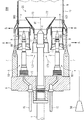
図1はノズルケース6とノズルケース下部5とを備えたバーナ100を示している。点火燃料用の噴射開口4を有するパイロットバーナ1がノズルケース6を貫通して延び、ノズルケース下部5に固定されている。複数の主燃料ノズル2がパイロットバーナ1に対して平行にノズルケース6を貫通して延び、ノズルケース下部5に固定されている。燃料供給管16がそれらの主燃料ノズル2に燃料を供給する。
FIG. 1 shows a
主燃焼域9が外被管19の内部に形成されている。パイロット円錐胴20がパイロットバーナ1の点火燃料用の噴射開口4の近くから突出し、主燃焼域9のそばに円錐状拡張端22を有している。パイロット円錐胴20は点火火炎域23を形成する形状を有している。
A main combustion zone 9 is formed inside the
圧縮空気101が圧縮機50から支えリブ7間を通り、主燃焼空気旋回装置8を通って主燃焼域9に流入する。各主燃焼空気旋回装置8はパイロットバーナ1に対して平行に延び、主燃焼域9に隣接している。各主燃料ノズル2はそれぞれ旋回翼(旋回流発生器)80により包囲されている。それらの旋回翼80は圧縮空気101と燃料102を互いに混合するために旋回流を発生させる。燃料・空気混合気103は主燃焼域9に運ばれ、そこで燃焼される。
圧縮空気101はパイロット旋回翼11の内部に存在する静止羽根10を通っても点火火炎域23に侵入する。その圧縮空気101はパイロット円錐胴20の内部で点火燃料30と混合し、点火火炎域ないしパイロット火炎域23に搬送され、そこで燃焼される。
The
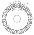
図2は図1のバーナ100をA−A線に沿った断面図で示している。図2に示されているように、パイロットバーナ1は複数の主燃料ノズル2によって環状に取り囲まれている。各主燃料ノズル2は旋回翼80から成る主燃焼空気旋回装置8でそれぞれ取り囲まれている。それらの主燃焼空気旋回装置8は相互に間隔dを隔てられている。この形態において、パイロットバーナ1は互いに等間隔を隔てて配置された複数の主燃料ノズル2によって取り囲まれているが、その主燃料ノズル2間の間隔は変化させることもできる。パイロット円錐胴20の円錐拡張端22は外被管19と共に円環状流路を形成している。燃料・空気混合気103はその円環状流路を通って主燃焼域20に流入する。
FIG. 2 shows the
主燃焼空気旋回装置8間における、以下において隙間とも呼ぶ、空間での混合気の望ましくない点火を防止するために、その主燃焼空気旋回装置8間の隙間は空気で強力に洗流される。その空気は混合の向上のためにおよび/又は最大燃焼温度の低減のために限られた範囲でしか利用できない。燃料と空気の希薄混合気が冷却して低温燃焼されることによって、NOx発生量が低下されることが知られているので、洗流に必要な空気は単純な様式で最少にすることが望ましい。
In order to prevent undesired ignition of the air-fuel mixture in the space between the main
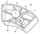
図3は特にガスタービンにおける旋回翼(旋回流発生器)90を示している。この旋回翼90は囲壁Bを有し、この囲壁Bは主燃料ノズル軸線Aに対して垂直な横断面が台形の形をしている。その旋回翼90は少なくとも1つのねじれ羽根91を有している。旋回翼90はほぼ中央にあるハブ92に配置されている。このハブ92を通して燃料の供給も行われる。そのために、中央ハブ92は燃料管に接続されている。そのねじれ羽根91は、好適には、三次元形状羽根として形成されている。燃料はハブ92あるいは複数のねじれ羽根から注入することができる。それらの羽根は三次元的流れ場のより良い空力学的流れを生じさせる。特に囲壁Bの複数の隅で三次元形状羽根を使用することができる。囲壁Bの複数の隅に追加的に、横断面の隅から尖っているコーナー羽根96を設けることもできる。これらのコーナー羽根96は囲壁Bの複数の隅に配置され、ハブ92まで延びることができるが、囲壁Bとハブ92との間で終端することもできる。これによって、より一様でより良好な流れ状態が得られる。また、囲壁Bの複数の隅が流出空気で貫流されることも有利であり、これによって、それらの隅は特に有利に逆火から保護される。燃料噴射用の複数のねじれ羽根91は旋回翼90の囲壁Bに固く結合されている。あるいはまた、それらのねじれ羽根91はハブ92だけに結合され、いわば部品としてハブ92だけに懸架されることもできる。これは製造技術的により簡単に製造でき、従ってコスト削減が図れる。
FIG. 3 particularly shows a swirl vane (swirl flow generator) 90 in a gas turbine. The
図4は複数の旋回翼90a、90bから構成された旋回翼装置(旋回翼配列構造)95を示している。それらの旋回翼90a、90bはパイロットバーナ1の周りに同心的に環状に配置されている。それらの旋回翼90a、90bは相互に小さな間隔d1を隔てられている。囲壁Bの横断面が台形であることによって、有利な幾何学的形状により、複数のセグメントを有する環状の隙間輪郭が円周方向に形成されるので、旋回翼はパイロット円錐胴20の平面に非常に近づけて設置できる。
FIG. 4 shows a swirler device (swirler arrangement structure) 95 composed of a plurality of
本発明によって、円周方向にセグメント化された旋回流をそれぞれ発生する横断面が非円形の旋回翼(旋回流発生器)が形成されている。さらに本発明によって、上述した隙間における望ましくない点火を防止するために、その隙間を通して少量の空気を貫流させるだけで済む。これによって、多量の空気が燃焼に用立てられる。もう1つの利点は単純な機械的形態にあり、これに伴って、より頑丈になり、かつより安価に製造できる。 According to the present invention, swirl vanes having a non-circular cross-section (swirl flow generator) that generate swirl flows segmented in the circumferential direction are formed. Furthermore, according to the present invention, only a small amount of air has to flow through the gap to prevent unwanted ignition in the gap. As a result, a large amount of air is used for combustion. Another advantage lies in the simple mechanical form, which makes it more robust and cheaper to manufacture.
1 パイロットバーナ
20 パイロット円錐胴
90 旋回翼(旋回流発生器)
91 ねじれ羽根
92 ハブ
95 旋回翼装置(旋回翼配列構造)
96 コーナー羽根
A 主燃料ノズル軸線
B (旋回翼)囲壁
1
91
96 Corner blade A Main fuel nozzle axis B (Swirl blade) Enclosure
Claims (8)
主燃料ノズル軸線(A)に対して垂直な囲壁(B)の横断面が台形状であることを特徴とする旋回翼。 A hub (92) disposed along the main fuel nozzle axis (A), and a surrounding wall surrounding the hub (92) at a distance from the hub (92) and having at least one twisted blade (91) A swirl vane (90) having a blade (91) extending radially outward from a hub (92) to a surrounding wall (B),
A swirl vane characterized in that the cross section of the surrounding wall (B) perpendicular to the main fuel nozzle axis (A) is trapezoidal.
Applications Claiming Priority (2)
| Application Number | Priority Date | Filing Date | Title |
|---|---|---|---|
| EP08013950.4 | 2008-08-04 | ||
| EP08013950A EP2151630B1 (en) | 2008-08-04 | 2008-08-04 | Swirler |
Publications (4)
| Publication Number | Publication Date |
|---|---|
| JP2010038538A JP2010038538A (en) | 2010-02-18 |
| JP2010038538A6 JP2010038538A6 (en) | 2010-05-06 |
| JP2010038538A5 JP2010038538A5 (en) | 2012-08-02 |
| JP5574635B2 true JP5574635B2 (en) | 2014-08-20 |
Family
ID=40351605
Family Applications (1)
| Application Number | Title | Priority Date | Filing Date |
|---|---|---|---|
| JP2009179079A Expired - Fee Related JP5574635B2 (en) | 2008-08-04 | 2009-07-31 | Swirl |
Country Status (3)
| Country | Link |
|---|---|
| EP (1) | EP2151630B1 (en) |
| JP (1) | JP5574635B2 (en) |
| AT (1) | ATE528589T1 (en) |
Families Citing this family (3)
| Publication number | Priority date | Publication date | Assignee | Title |
|---|---|---|---|---|
| DE102012002465A1 (en) * | 2012-02-08 | 2013-08-08 | Rolls-Royce Deutschland Ltd & Co Kg | Gas turbine combustor with unsymmetrical fuel nozzles |
| US20180335214A1 (en) * | 2017-05-18 | 2018-11-22 | United Technologies Corporation | Fuel air mixer assembly for a gas turbine engine combustor |
| CN114413284A (en) * | 2021-12-28 | 2022-04-29 | 北京动力机械研究所 | Special-shaped swirler matched with head of annular combustion chamber |
Family Cites Families (15)
| Publication number | Priority date | Publication date | Assignee | Title |
|---|---|---|---|---|
| JPS6122127A (en) * | 1984-07-10 | 1986-01-30 | Hitachi Ltd | gas turbine combustor |
| JPH02267419A (en) * | 1989-04-10 | 1990-11-01 | Hitachi Ltd | Gas turbine combustor |
| US5359847B1 (en) * | 1993-06-01 | 1996-04-09 | Westinghouse Electric Corp | Dual fuel ultra-flow nox combustor |
| FR2751054B1 (en) * | 1996-07-11 | 1998-09-18 | Snecma | ANNULAR TYPE FUEL INJECTION ANTI-NOX COMBUSTION CHAMBER |
| US6038861A (en) * | 1998-06-10 | 2000-03-21 | Siemens Westinghouse Power Corporation | Main stage fuel mixer with premixing transition for dry low Nox (DLN) combustors |
| US6119459A (en) * | 1998-08-18 | 2000-09-19 | Alliedsignal Inc. | Elliptical axial combustor swirler |
| JP2002031343A (en) * | 2000-07-13 | 2002-01-31 | Mitsubishi Heavy Ind Ltd | Fuel injection member, burner, premixing nozzle of combustor, combustor, gas turbine and jet engine |
| JP2002213746A (en) * | 2001-01-19 | 2002-07-31 | Mitsubishi Heavy Ind Ltd | Burner, premix fuel nozzle of combustor, and an combustor |
| JP4610796B2 (en) * | 2001-06-13 | 2011-01-12 | 三菱重工業株式会社 | Gas turbine combustor |
| JP3986348B2 (en) * | 2001-06-29 | 2007-10-03 | 三菱重工業株式会社 | Fuel supply nozzle of gas turbine combustor, gas turbine combustor, and gas turbine |
| JP4610800B2 (en) * | 2001-06-29 | 2011-01-12 | 三菱重工業株式会社 | Gas turbine combustor |
| JP2003130351A (en) * | 2001-10-18 | 2003-05-08 | Mitsubishi Heavy Ind Ltd | Combustor, gas turbine and jet engine |
| JP4070758B2 (en) * | 2004-09-10 | 2008-04-02 | 三菱重工業株式会社 | Gas turbine combustor |
| JP4486549B2 (en) * | 2005-06-06 | 2010-06-23 | 三菱重工業株式会社 | Gas turbine combustor |
| JP4476177B2 (en) * | 2005-06-06 | 2010-06-09 | 三菱重工業株式会社 | Gas turbine combustion burner |
-
2008
- 2008-08-04 EP EP08013950A patent/EP2151630B1/en not_active Not-in-force
- 2008-08-04 AT AT08013950T patent/ATE528589T1/en active
-
2009
- 2009-07-31 JP JP2009179079A patent/JP5574635B2/en not_active Expired - Fee Related
Also Published As
| Publication number | Publication date |
|---|---|
| ATE528589T1 (en) | 2011-10-15 |
| JP2010038538A (en) | 2010-02-18 |
| EP2151630A1 (en) | 2010-02-10 |
| EP2151630B1 (en) | 2011-10-12 |
Similar Documents
| Publication | Publication Date | Title |
|---|---|---|
| JP4610800B2 (en) | Gas turbine combustor | |
| JP5615008B2 (en) | Swirler and burner with at least one swirler | |
| JP5911672B2 (en) | Combustor liner for turbine engines | |
| JP5746091B2 (en) | Robe swirler | |
| CA1258379A (en) | Gas turbine combustor | |
| US8904798B2 (en) | Combustor | |
| JP3986348B2 (en) | Fuel supply nozzle of gas turbine combustor, gas turbine combustor, and gas turbine | |
| CN101201176B (en) | Fuel injection slot jet and method for enhancing mixing in premixing devices | |
| CN205481129U (en) | A fuel injector for gas turbine engine's combustor | |
| CN206113000U (en) | A fuel injector for gas turbine engine's combustor | |
| US6701713B2 (en) | Pilot burner, premixing combustor, and gas turbine | |
| US11421882B2 (en) | Swirler, combustor assembly, and gas turbine with improved fuel/air mixing | |
| KR101412237B1 (en) | Gas turbine combustor and gas turbine | |
| EP3211316A1 (en) | Pilot nozzles in gas turbine combustors | |
| JP2010223577A6 (en) | Swirl, method for preventing backfire in burner equipped with at least one swirler, and burner | |
| JP2010223577A5 (en) | ||
| KR101774630B1 (en) | Tangential annular combustor with premixed fuel and air for use on gas turbine engines | |
| EP1134494A1 (en) | Gas turbine combustor | |
| JP2012017971A5 (en) | ||
| JP2009156542A (en) | Burner for gas turbine | |
| JP6086860B2 (en) | Nozzle, combustor, and gas turbine | |
| JP7254540B2 (en) | Burner, combustor and gas turbine equipped with the same | |
| JP2015036554A (en) | Burner arrangement and method for operating burner arrangement | |
| CN107525096B (en) | Multi-tube late lean injector | |
| CN110094759B (en) | Cone-flat heat shields for gas turbine engine combustor shrouds |
Legal Events
| Date | Code | Title | Description |
|---|---|---|---|
| A521 | Request for written amendment filed |
Free format text: JAPANESE INTERMEDIATE CODE: A523 Effective date: 20101228 |
|
| A521 | Request for written amendment filed |
Free format text: JAPANESE INTERMEDIATE CODE: A523 Effective date: 20110302 |
|
| RD03 | Notification of appointment of power of attorney |
Free format text: JAPANESE INTERMEDIATE CODE: A7423 Effective date: 20110302 |
|
| A521 | Request for written amendment filed |
Free format text: JAPANESE INTERMEDIATE CODE: A523 Effective date: 20120618 |
|
| A621 | Written request for application examination |
Free format text: JAPANESE INTERMEDIATE CODE: A621 Effective date: 20120618 |
|
| A977 | Report on retrieval |
Free format text: JAPANESE INTERMEDIATE CODE: A971007 Effective date: 20130614 |
|
| A131 | Notification of reasons for refusal |
Free format text: JAPANESE INTERMEDIATE CODE: A131 Effective date: 20130625 |
|
| A601 | Written request for extension of time |
Free format text: JAPANESE INTERMEDIATE CODE: A601 Effective date: 20130924 |
|
| A602 | Written permission of extension of time |
Free format text: JAPANESE INTERMEDIATE CODE: A602 Effective date: 20130927 |
|
| A601 | Written request for extension of time |
Free format text: JAPANESE INTERMEDIATE CODE: A601 Effective date: 20131125 |
|
| A602 | Written permission of extension of time |
Free format text: JAPANESE INTERMEDIATE CODE: A602 Effective date: 20131128 |
|
| A521 | Request for written amendment filed |
Free format text: JAPANESE INTERMEDIATE CODE: A523 Effective date: 20131209 |
|
| TRDD | Decision of grant or rejection written | ||
| A01 | Written decision to grant a patent or to grant a registration (utility model) |
Free format text: JAPANESE INTERMEDIATE CODE: A01 Effective date: 20140603 |
|
| A61 | First payment of annual fees (during grant procedure) |
Free format text: JAPANESE INTERMEDIATE CODE: A61 Effective date: 20140701 |
|
| R150 | Certificate of patent or registration of utility model |
Ref document number: 5574635 Country of ref document: JP Free format text: JAPANESE INTERMEDIATE CODE: R150 |
|
| LAPS | Cancellation because of no payment of annual fees |