JP5574155B2 - Motor control device - Google Patents
Motor control device Download PDFInfo
- Publication number
- JP5574155B2 JP5574155B2 JP2010037517A JP2010037517A JP5574155B2 JP 5574155 B2 JP5574155 B2 JP 5574155B2 JP 2010037517 A JP2010037517 A JP 2010037517A JP 2010037517 A JP2010037517 A JP 2010037517A JP 5574155 B2 JP5574155 B2 JP 5574155B2
- Authority
- JP
- Japan
- Prior art keywords
- phase
- induced voltage
- normal
- turned
- switching element
- Prior art date
- Legal status (The legal status is an assumption and is not a legal conclusion. Google has not performed a legal analysis and makes no representation as to the accuracy of the status listed.)
- Expired - Fee Related
Links
Images


Description
この発明は、三相ブラシレスモータを駆動するためのモータ制御装置に関する。三相ブラシレスモータは、たとえば、電動パワーステアリング装置における操舵補助力の発生源として利用される。 The present invention relates to a motor control device for driving a three-phase brushless motor. A three-phase brushless motor is used, for example, as a generation source of steering assist force in an electric power steering apparatus.
電動パワーステアリング装置に使用されているブラシレスモータの駆動回路は、FET(Field Effect Transistor)などのスイッチング素子を含んでいる。スイッチング素子に故障が発生すると、ステアリングホイールを操作するときにブラシレスモータが負荷となり、操舵が重くなるおそれがある。このような問題に対処するために、ブラシレスモータと駆動回路との結線にリレーが挿入されている。たとえば、三相ブラシレスモータの場合には、二相のモータ結線にそれぞれリレーを挿入し、無制御時およびスイッチング素子の故障時には、それらのリレーをオフするようにしている。 The drive circuit of the brushless motor used in the electric power steering apparatus includes a switching element such as an FET (Field Effect Transistor). When a failure occurs in the switching element, the brushless motor becomes a load when the steering wheel is operated, and there is a possibility that the steering becomes heavy. In order to cope with such a problem, a relay is inserted in the connection between the brushless motor and the drive circuit. For example, in the case of a three-phase brushless motor, a relay is inserted into each of the two-phase motor connections, and these relays are turned off when there is no control and when the switching element fails.
上記の先行技術では、モータ駆動回路内のスイッチング素子が故障した時には、リレーをオフしているため、ブラシレスモータを駆動することができない。そのため、電動パワーステアリング装置においては、操舵補助力(アシスト力)を発生させることができない。
この発明の目的は、三相ブラシレスモータの駆動回路内の1個のスイッチング素子が開放故障した場合または同相の2つのスイッチング素子が開放故障した場合において、他の正常な二相によって三相ブラシレスモータを駆動することができるモータ制御装置を提供することである。
In the above prior art, when the switching element in the motor drive circuit fails, the relay is turned off, so the brushless motor cannot be driven. Therefore, in the electric power steering device, it is not possible to generate a steering assist force (assist force).
An object of the present invention is to provide a three-phase brushless motor by another normal two-phase when one switching element in the driving circuit of the three-phase brushless motor fails to open or when two in-phase switching elements fail to open. It is providing the motor control apparatus which can drive.
上記の目的を達成するための請求項1に記載の発明は、三相ブラシレスモータ(18)を制御するためのモータ制御装置であって、2個のスイッチング素子(31UH,31UL;31VH,31VL;31WH,31WL)が直列に接続された直列回路を三相の各相に対応して3組備え、かつ電源(33)と接地(34)間においてそれらの直列回路が並列接続されている駆動回路(30)と、前記複数のスイッチング素子のうちの1つのスイッチング素子または同相の2つのスイッチング素子が開放故障したときに、全てのスイッチング素子をオフにさせる手段(41,42,S1)と、開放故障したスイッチング素子に対応する故障相以外の2つの正常相のうち少なくとも一方に対応する誘起電圧を監視する手段(41)と、前記監視手段によって監視されている正常相の誘起電圧に対して同位相の電流がその正常相に流れるように、当該正常相に対応するスイッチング素子を制御する制御手段(41,43,S2〜S5)とを含み、前記制御手段は、2つの正常相のうち少なくとも一方の正常相の誘起電圧が正極性の所定のしきい値(Vth1)より大きくなったときに、当該正常相のハイサイドスイッチング素子をオンさせるとともに、他方の正常相のローサイドスイッチング素子をオンさせる第1手段(43)と、2つの正常相のうち少なくとも一方の正常相の誘起電圧が負極性の所定のしきい値(Vth2)より小さくなったときに、当該正常相のローサイドスイッチング素子をオンさせるとともに、他方の正常相のハイサイドスイッチング素子をオンさせる第2手段(43)とを含む、なお、括弧内の英数字は、後述の実施形態における対応構成要素等を表すが、むろん、この発明の範囲は当該実施形態に限定されない。以下、この項において同じ。
In order to achieve the above object, an invention according to
上記構成では、複数のスイッチング素子のうちの1つのスイッチング素子または同相の2つのスイッチング素子が開放故障したときに、全てのスイッチング素子がオフにされる。これにより、三相ブラシレスモータの駆動が停止される。この後、開放故障したスイッチング素子に対応する故障相以外の2つの正常相のうち少なくとも一方に対応する誘起電圧が監視される。そして、監視されている正常相の誘起電圧に対して同位相の電流がその正常相に流れるように、当該正常相に対応するスイッチング素子が制御される。
具体的には、2つの正常相(たとえば、U相,V相)のうち少なくとも一方の正常相(U相)の誘起電圧(V U )が正極性のしきい値(Vth1)より大きくなったときに、当該正常相のハイサイドスイッチング素子(31 UH )がオンされるとともに、他方の正常相(V相)のローサイドスイッチング素子(31 VL )がオンされる。この場合には、正常相であるU相の界磁コイル(18U)に、電源(33)から、この相に発生している誘起電圧と同位相の電流が流れるので、ブラシレスモータ(18)が駆動される。
また、2つの正常相(たとえば、U相,V相)のうち少なくとも一方の正常相(U相)の誘起電圧(V U )が負極性のしきい値(Vth2)より小さくなったときに、当該正常相のローサイドスイッチング素子(31 UL )がオンされるとともに、他方の正常相(V相)のハイサイドスイッチング素子(31 VH )がオンされる。この場合には、正常相であるU相の界磁コイル(18U)に、電源(33)から、この相に発生している誘起電圧と同位相の電流が流れるので、ブラシレスモータ(18)が駆動される。
したがって、三相ブラシレスモータが電動パワーステアリング装置に使用されている場合には、スイッチング素子が開放故障した場合においても、操舵補助を行うことが可能となる。
In the above configuration, when one of the plurality of switching elements or two switching elements having the same phase has an open failure, all the switching elements are turned off. As a result, the driving of the three-phase brushless motor is stopped. Thereafter, the induced voltage corresponding to at least one of the two normal phases other than the failure phase corresponding to the switching element that has failed open is monitored. Then, the switching element corresponding to the normal phase is controlled such that a current having the same phase flows in the normal phase with respect to the induced voltage of the normal phase being monitored .
Specifically, the induced voltage (V U ) of at least one normal phase (U phase) out of two normal phases (for example, U phase and V phase ) is greater than the positive threshold (Vth1). Sometimes, the normal-phase high-side switching element (31 UH ) is turned on, and the other normal-phase (V-phase) low-side switching element (31 VL ) is turned on. In this case, since a current having the same phase as the induced voltage generated in this phase flows from the power source (33) to the normal phase U-phase field coil (18U), the brushless motor (18) Driven.
Further, when the induced voltage (V U ) of at least one normal phase (U phase) of two normal phases (for example, U phase and V phase) becomes smaller than the negative polarity threshold (Vth2), The normal-phase low-side switching element ( 31UL ) is turned on, and the other normal-phase (V-phase) high-side switching element ( 31VH ) is turned on. In this case, since a current having the same phase as the induced voltage generated in this phase flows from the power source (33) to the normal phase U-phase field coil (18U), the brushless motor (18) Driven.
Therefore, when the three-phase brushless motor is used in an electric power steering apparatus, even when the switching element is open-circuit failure, it is possible to perform steering assist.
請求項2に記載の発明は、前記制御手段によってスイッチング素子がオンされる時間が、一定である請求項1に記載のモータ制御装置である。この構成では、制御手段によってスイッチング素子がオンされたときには、オンされてから一定時間が経過したときに、当該スイッチング素子がオフされる。
The invention described in 請 Motomeko 2, the time the switching element is turned on by the control means is a motor control device according to
請求項3に記載の発明は、前記第1手段によってスイッチング素子がオンされる時間は、前記誘起電圧が正極性の所定の第1のしきい値(Vth1)より大きくなってから正極性の所定の第2のしきい値以下となるまでの期間であり、前記第2手段によってスイッチング素子がオンされる時間は、前記誘起電圧が負極性の所定の第1のしきい値(Vth2)より小さくなってから負極性の所定の第2のしきい値以上となるまでの期間である請求項4に記載のモータ制御装置である。この構成では、第1手段では、誘起電圧が正極性の第1のしきい値より大きくなってから正極性の所定の第2のしきい値以下となるまでの期間、スイッチング素子がオンされる。一方、第2手段では、誘起電圧が負極性の第1のしきい値より小さくなってから負極性の所定の第2のしきい値以上となるまでの期間、スイッチング素子がオンされる。
According to a third aspect of the present invention, the time during which the switching element is turned on by the first means is the predetermined positive polarity after the induced voltage becomes larger than the positive first threshold value (Vth1). The time until the switching element is turned on by the second means is less than a predetermined first threshold value (Vth2) having a negative polarity. 5. The motor control device according to
なお、前記正極性の第1のしきい値と、前記正極性の第2のしきい値とは同じ値であってもよい。また、前記負極性の第1のしきい値と、前記負極性の第2のしきい値とは同じ値であってもよい。 The positive first threshold value and the positive second threshold value may be the same value. The negative first threshold value and the negative second threshold value may be the same value.
以下では、この発明の実施形態を、添付図面を参照して詳細に説明する。
図1は、本発明の一実施形態に係るモータ制御装置が適用された、電動パワーステアリング装置の概略構成を示す模式図である。
電動パワーステアリング装置1は、操舵部材としてのステアリングホイール2と、このステアリングホイール2の回転に連動して転舵輪3を転舵する転舵機構4と、運転者の操舵を補助するための操舵補助機構5とを備えている。ステアリングホイール2と転舵機構4とは、ステアリングシャフト6および中間軸7を介して機械的に連結されている。
Hereinafter, embodiments of the present invention will be described in detail with reference to the accompanying drawings.
FIG. 1 is a schematic diagram showing a schematic configuration of an electric power steering device to which a motor control device according to an embodiment of the present invention is applied.
The electric
ステアリングシャフト6は、直線状に延びている。また、ステアリングシャフト6は、ステアリングホイール2に連結された入力軸8と、中間軸7に連結された出力軸9とを含む。入力軸8と出力軸9とは、トーションバー10を介して同一軸線上で相対回転可能に連結されている。すなわち、ステアリングホイール2が回転されると、入力軸8および出力軸9は、互いに相対回転しつつ同一方向に回転するようになっている。
The steering shaft 6 extends linearly. Steering shaft 6 includes an
ステアリングシャフト6の周囲に配置されたトルクセンサ11は、入力軸8および出力軸9の相対回転変位量に基いて、ステアリングホイール2に与えられた操舵トルクを検出する。トルクセンサ11によって検出される操舵トルクは、ECU(電子制御ユニット:Electronic Control Unit)12に入力される。また、ECU12には、車速センサ23によって検出される車速が入力される。
A
転舵機構4は、ピニオン軸13と、転舵軸としてのラック軸14とを含むラックアンドピニオン機構からなる。ラック軸14の各端部には、タイロッド15およびナックルアーム(図示略)を介して転舵輪3が連結されている。ピニオン軸13は、中間軸7に連結されている。ピニオン軸13は、ステアリングホイール2の操舵に連動して回転するようになっている。ピニオン軸13の先端(図1では下端)には、ピニオン16が連結されている。
The steered
ラック軸14は、自動車の左右方向に沿って直線状にのびている。ラック軸14の軸方向の中間部には、ピニオン16に噛み合うラック17が形成されている。このピニオン16およびラック17によって、ピニオン軸13の回転がラック軸14の軸方向移動に変換される。ラック軸14を軸方向に移動させることによって、転舵輪3を転舵することができる。
The
ステアリングホイール2が操舵(回転)されると、この回転が、ステアリングシャフト6および中間軸7を介して、ピニオン軸13に伝達される。そして、ピニオン軸13の回転は、ピニオン16およびラック17によって、ラック軸13の軸方向移動に変換される。これにより、転舵輪3が転舵される。
操舵補助機構5は、操舵補助用の電動モータ18と、電動モータ18の出力トルクを転舵機構4に伝達するための減速機構19とを含む。電動モータ3は、この実施形態では、三相ブラシレスモータからなる。減速機構19は、ウォーム軸20と、このウォーム軸20と噛み合うウォームホイール21とを含むウォームギア機構からなる。減速機構19は、伝達機構ハウジングとしてのギヤハウジング22内に収容されている。
When the
The
ウォーム軸20は、電動モータ18によって回転駆動される。また、ウォームホイール21は、ステアリングシャフト6とは同方向に回転可能に連結されている。ウォームホイール21は、ウォーム軸20によって回転駆動される。
電動モータ18によってウォーム軸20が回転駆動されると、ウォームホイール21が回転駆動され、ステアリングシャフト6が回転する。そして、ステアリングシャフト6の回転は、中間軸7を介してピニオン軸13に伝達される。ピニオン軸13の回転は、ラック軸14の軸方向移動に変換される。これにより、転舵輪3が転舵される。すなわち、電動モータ18によってウォーム軸2を回転駆動することによって、転舵輪3が転舵されるようになっている。
The
When the
電動モータ18は、モータ制御装置としてのECU12によって制御される。ECU12は、トルクセンサ11によって検出される操舵トルク、車速センサ23によって検出される車速等に基いて、電動モータ18を制御する。具体的には、ECU12では、操舵トルクと目標アシスト量との関係を車速ごとに記憶したマップを用いて目標アシスト量を決定し、電動モータ18の発生するアシスト力が目標アシスト量に近づくように制御する。
The
この実施形態では、電動モータ18は、位置センサレス駆動されている。つまり、レゾルバ等のロータの回転角(位置)を検出するための位置センサを用いることなく、駆動される。ロータの回転角は、この実施形態では、電動モータ18の誘起電圧に基いて演算される。
図2は、モータ制御装置としてのECU12の電気的構成を示す概略図である。電動モータ18は、U相界磁コイル18U、V相界磁コイル18V、W相界磁コイル18Wを有するステータと、これらの界磁コイル18U,18V,18Wからの反発磁界を受ける永久磁石が固定されたロータとを備えている。
In this embodiment, the
FIG. 2 is a schematic diagram showing an electrical configuration of the
ECU12は、電動モータ18の駆動電力を生成する駆動回路30と、駆動回路30を制御するための制御部40とを備えている。制御部40は、CPUとこのCPUの動作プログラム等を記憶したメモリとを含むマイクロコンピュータで構成されている。
駆動回路30は、三相ブリッジインバータ回路である。この駆動回路30では、電動モータ18のU相に対応した一対のFET(電界効果トランジスタ)31UH,31ULの直列回路と、V相に対応した一対のFET31VH,31VLの直列回路と、W相に対応した一対のFET31WH,31WLの直列回路とが、直流電源33と接地34との間に並列に接続されている。また、各FET31UH〜31WLには、それぞれ回生ダイオード32UH〜32WLが、接地34側から直流電源33側に順方向電流が流れるような向きで、並列に接続されている。
The
The
以下において、各相の一対のFETのうち、電源33側のものを「ハイサイドFET」といい、接地34側のものを「ローサイドFET」という場合がある。また、6つのFET31UH〜31WLを総称する場合には、「FET31」ということにする。同様に、6つの回生ダイオード32UH〜32WLを総称する場合には、「回生ダイオード32」ということにする。
Hereinafter, among the pair of FETs of each phase, the one on the
電動モータ18のU相界磁コイル18Uは、U相に対応した一対のFET31UH,31ULの間の接続点に接続されている。電動モータ18のV相界磁コイル18Vは、V相に対応した一対のFET31VH,31VLの間の接続点に接続されている。電動モータ18のW相界磁コイル18Wは、W相に対応した一対のFET31WH,31WLの間の接続点に接続されている。各相の界磁コイル18U,18V,18Wと駆動回路30とを接続するための各接続線には、各相の相電流IU,IV,IWを検出するための電流センサ51U,51V,51Wが設けられている。
The
制御部40は、メモリに格納された所定の動作プログラムを実行することによって、複数の機能処理部として機能するようになっている。この複数の機能処理部には、故障判定部41と、正弦波駆動部42と、二相駆動部43とが含まれる。
正弦波駆動部42は、FET31に故障が発生していない通常時において、各FET31を制御することにより、電動モータ18を正弦波駆動するものである。正弦波駆動部42には、電動モータ18の各相電圧VU,VV,VWが与えられる。また、正弦波駆動部42には、トルクセンサ11によって検出される操舵トルクと、車速センサ23によって検出される車速と、電流センサ51U,51V,51Wによって検出される各相の相電流IU,IV,IWが入力される。正弦波駆動部42は、たとえば、180°通電方式によって電動モータ18を正弦波駆動するものであり、各相の誘起電圧(逆起電力)を演算し、それに基いてロータの回転角を演算する。また、正弦波駆動部42は、たとえば、操舵トルクと目標アシスト量(電流目標値)との関係を車速毎に記憶したマップと、トルクセンサ11によって検出された操舵トルクと、車速センサ23によって検出された車速とに基づいて、目標アシスト量を決定する。そして、正弦波駆動部42は、目標アシスト量と、相毎に検出される相電流と、誘起電圧から演算されたロータの回転角とに基いて、電動モータ18の発生するアシスト力(トルク)が目標アシスト量に近づくように、各FET31をPWM(Pulse Width Modulation)制御する。
The
The sine
故障判定部41は、電動モータ18の異常が検出されたときに、電動モータ18を停止させるための制御、FET31に開放故障が発生しているか否かの判定、FET31に開放故障が発生している場合に開放故障が発生しているFET31の特定等を行う。
二相駆動部43は、故障判定部41によって、FET31に開放故障が発生していると判定され、その開放故障が発生しているFET31が特定された場合に、正常な2相で電動モータ18を駆動させるものである。より具体的には、6つのFET31のうちの1つのFET31または同相の2つのFET31が開放故障した場合において、故障判定部41によって開放故障が発生しているFET31が特定されたときに、二相駆動部43は、正常な2相で電動モータ18を駆動させる。
The
When the
図3は、故障が発生したときのモータ制御部40の動作を示すフローチャートである。
故障判定部41は、電動モータ18が正弦波駆動部42によって正弦波駆動されている場合に、電動モータ18に動作不良(故障)が発生したことを検出すると、正弦波駆動部42にモータ停止指令に与える(ステップS1)。正弦波駆動部42は、故障判定部41からのモータ停止指令を受信すると、正弦波駆動を中止して、全てのFET31をオフにさせる。これにより、電動モータ18が停止する。
FIG. 3 is a flowchart showing the operation of the
When the
この後、故障判定部41は、相電圧VU,VV,VWに基いて、開放故障が発生している可能性があるか否かを判別する(ステップS2)。具体的には、故障判定部41は、相電圧VU,VV,VWのいずれかが、所定のグランドレベルVG(たとえば0.5[V])より大きくかつ所定の電源レベルVB(たとえば5.0[V])より低ければ、開放故障が発生している可能性があると判別する。この判別が妥当な理由について、説明する。ハイサイドFET31UH,31VH,31WHのいずれかに短絡故障が生じている場合には、各相電圧VU,VV,VWは所定の電源レベルVB以上となり、ローサイドFET31UL,31VL,31WLのいずれかに短絡故障が生じている場合には、各相電圧VU,VV,VWは所定のグランドレベルVG以下となる。したがって、各相電圧VU,VV,VWが、所定のグランドレベルVGより大きくかつ所定の電源レベルVBより低い場合には、いずれのFET31にも短絡故障が生じていないので、開放故障が発生している可能性があると判別できる。なお、この判別は、全ての相電圧を調べる必要はなく、いずれか一相の相電圧を調べることにより行うことができる。
Thereafter, the
開放故障が発生している可能性がないと判別された場合には(ステップS2:NO)、故障判定部41は、後述する二相駆動制御以外の処理(以下、「他の処理」という)を行なう(ステップS6)。この「他の処理」には、何ら処理を行なわないことも含まれる。開放故障が発生している可能性があると判別された場合には(ステップS2:YES)、故障判定部41は、故障箇所の特定処理を行なう(ステップS3)。具体的には、故障判定部41は、各FET31を個別にオンしていく。ハイサイドFET31UH,31VH,31WHを個別にオンした場合に、各相電圧VU,VV,VWが所定の電源レベルVB以上に変化した場合には、当該FETは正常であり、ローサイドFET31UL,31VL,31WLを個別にオンした場合に、各相電圧VU,VV,VWが所定のグラウンドレベルVG以下に変化した場合には、当該FETは正常である。したがって、故障判定部41は、各FET31を個別にオンしたときに、各相電圧VU,VV,VWに変化がない場合には、当該FETが開放故障していると判定する。なお、この判定は、全ての相電圧を調べる必要はなく、いずれか一相の相電圧を調べることにより行うことができる。
When it is determined that there is no possibility that an open failure has occurred (step S2: NO), the
故障判定部41は、故障箇所の特定処理によって開放故障が発生しているFET31を特定できなかった場合には(ステップS4:NO)、二相駆動制御以外の処理(「他の処理」)を行なう(ステップS6)。一方、故障箇所の特定処理によって開放故障が発生しているFET31を特定できた場合には(ステップS4:YES)、故障判定部41は二相駆動部43に二相駆動制御を開始させる(ステップS5)。ただし、開放故障が発生しているFET31が1つだけである場合または開放故障が発生しているFET31が同相の2つのFET31だけである場合において、開放故障が発生しているFET31を特定できた場合にのみ、ステップS5に移行して二相駆動制御が開始される。3相のうちの2相以上においてFETが開放故障している場合には、開放故障が発生しているそれらのFET31を特定できた場合であっても、ステップS5に移行せずに、ステップS6に移行する。
When the
ステップS5においては、具体的には、故障判定部41は、二相駆動部43に、開放故障が発生しているFET31に対応する相を通知する。これにより、二相駆動部43は、二相駆動制御を開始する。以下において、開放故障が発生しているFET31に対応する相を「故障相」といい、それ以外の相を「正常相」という場合がある。
以下、二相駆動部43による二相駆動制御について説明する。まず、二相駆動制御の考え方について説明する。駆動回路30内の全てのFET31がオフとなっている場合において、運転者によってスアリングホイール2が回転されると、電動モータ18のロータが回転する。電動モータ18のロータが回転すると、ステータの界磁コイル18U,18V,18Wに誘起電圧が発生する。各相の誘起電圧は、位相が120°ずつずれた正弦波形となる。
In step S5, specifically, the
Hereinafter, the two-phase drive control by the two-
操舵によって界磁コイル18U,18V,18Wに発生する誘起電圧に対して同等以上の駆動電圧を与えることができれば、電動モータ18を駆動することができ、アシストが可能となる。駆動回路30から電動モータ18に向かって流れる電流の極性を正とすると、電動モータ18が発電機として動作するときの電圧と電流の位相関係は逆位相となり、アシスト時にはそれらの位相関係は同位相となる。したがって、電流がほとんど流れていない状態において、界磁コイル18U,18V,18Wに発生している誘起電圧と同位相の電流を瞬時でも当該界磁コイルに流すことができれば、アシストが可能となる。
If a drive voltage equal to or higher than the induced voltage generated in the field coils 18U, 18V, and 18W by steering can be applied, the
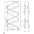
そこで、二相駆動部43は、2つの正常相の界磁コイルに、誘起電圧と同位相の電流が流れるように、駆動回路30を制御することにより、電動モータ18にアシスト力を発生させる。図4を参照して、より具体的に説明する。
図4は、W相に対応する一対のFET31WH,31WLのいずれか一方または両方が開放故障した場合の二相駆動部43の動作例を説明するための説明図である。図4において、VUは、一方の正常相(第1の正常相)であるU相の誘起電圧を示し、VVは他方の正常相(第2の正常相)であるV相の誘起電圧を示している。また、SUは、第1の正常相であるU相に対応するFET31UH,31ULに対する制御信号を示し、SVは、第2の正常相であるV相に対応するFET31VH,31VLに対する制御信号を示している。
Therefore, the two-
FIG. 4 is an explanatory diagram for explaining an operation example of the two-
U相に対応する制御信号SUがHレベルであるときには、U相に対応するハイサイドFET31UHがオンされ、当該制御信号SUがLレベルであるときには、U相に対応するローサイドFET31ULがオンされる。同様に、V相に対応する制御信号SVがHレベルであるときには、V相に対応するハイサイドFET31VHがオンされ、当該制御信号SVがLレベルであるときには、V相に対応するローサイドFET31VLがオンされる。 When the control signal S U corresponding to the U phase is at the H level, the high side FET 31 UH corresponding to the U phase is turned on, and when the control signal S U is at the L level, the low side FET 31 UL corresponding to the U phase is Turned on. Similarly, when the control signal S V corresponding to the V-phase is at the H level, the high side FET 31 VH is turned on corresponding to the V phase, when the control signal S V is at the L level, the low side corresponding to the V-phase The FET 31 VL is turned on.
第1の正常相であるU相の誘起電圧VUが正の極性の所定のしきい値Vth1より大きい期間(t3〜t4,t11〜t12)においては、二相駆動部43は、第1の正常相であるU相のハイサイドFET31UHをオンさせるとともに、第2の正常相であるV相のローサイドFET31VLをオンさせる。また、第2の正常相であるV相の誘起電圧VVが正の極性のしきい値Vth1より大きい期間(t5〜t6,t13〜t14)においては、二相駆動部43は、第2の正常相であるV相のハイサイドFET31VHをオンさせるとともに、第1の正常相であるU相のローサイドFET31ULをオンさせる。これにより、各正常相の誘起電圧が正の極性のしきい値Vth1より大きい期間において、その相の誘起電圧以上の駆動電圧がその相の界磁コイルに与えられるので、電動モータ18を駆動させることができる。この結果、電動モータ18による操舵のアシストが可能となる。なお、FET31をオンしてからオフさせるまでの期間は、図4に破線で示しているように、予め定めた一定期間(パルス幅一定)であってもよい。
Predetermined threshold Vth1 greater period of polarity induced voltage V U is positive in the first U-phase is normal phase (t3 to t4, t11 to t12) in the two-
操舵によって回転されるロータの回転速度が高いほど、誘起電圧は高くなるとともに、その周波数が高くなる。しかし、上記のように、FET31をオンする期間を誘起電圧がしきい値を超えている期間とした場合や、FET31をオンする期間を一定時間にした場合には、FET31のオンする周期も、それに応じて短くなるから、結局、電動モータ18に印加される電圧が高くなる。よって、ロータの回転速度が高くなると、アシスト時間(アシスト合計時間)が自動的に増加することになる。
The higher the rotational speed of the rotor rotated by steering, the higher the induced voltage and the higher the frequency. However, as described above, when the period during which the FET 31 is turned on is a period in which the induced voltage exceeds the threshold value, or when the period during which the FET 31 is turned on is a fixed time, the period during which the FET 31 is turned on is Since the voltage is shortened accordingly, the voltage applied to the
この代わりに、パルス幅を誘起電圧レベル(回転速度)に応じて変化させてもよい。つまり、誘起電圧レベル(回転速度)が高くなるほど、パルス幅を大きくする。また、誘起電圧レベル(回転速度)に応じてパルス幅変調制御(PWM制御)を行ってFET31をオンオフし、そのデューティ比を変化させてもよい。つまり、誘起電圧レベル(回転速度)が高くなるほど、デューティ比を大きくする。 Instead, the pulse width may be changed according to the induced voltage level (rotation speed). That is, the pulse width is increased as the induced voltage level (rotational speed) increases. Further, the pulse width modulation control (PWM control) may be performed according to the induced voltage level (rotation speed) to turn on / off the FET 31 and change its duty ratio. That is, the duty ratio is increased as the induced voltage level (rotational speed) increases.
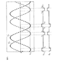
以上、この発明の一実施形態について説明したが、この発明はさらに他の形態で実施することもできる。たとえば、前述の実施形態では、各正常相の誘起電圧が正の極性の所定のしきい値Vth1より大きい期間において、その相の誘起電圧以上の電圧がその相の界磁コイルに与えられるように、正常相に対応するFET31を制御している。しかし、このような制御に代えて、各磁極に対各正常相の誘起電圧が負の極性の所定のしきい値より小さい期間において、その相の誘起電圧以上の電圧がその相の界磁コイルに与えられるように、正常相に対応するFET31を制御してもよい。 As mentioned above, although one Embodiment of this invention was described, this invention can also be implemented with another form. For example, in the above-described embodiment, in a period in which the induced voltage of each normal phase is larger than the predetermined threshold value Vth1 having a positive polarity, a voltage equal to or higher than the induced voltage of that phase is applied to the field coil of that phase. The FET 31 corresponding to the normal phase is controlled. However, instead of such control, in the period in which the induced voltage of each normal phase with respect to each magnetic pole is smaller than a predetermined threshold value of negative polarity, the voltage higher than the induced voltage of that phase is a field coil of that phase. The FET 31 corresponding to the normal phase may be controlled as shown in FIG.
具体的には、図5に示すように、故障相がたとえばW相である場合において、第1の正常相であるU相の誘起電圧VUが負の極性の所定のしきい値Vth2より小さい期間(t7〜t8,t15〜t16)においては、二相駆動部43は、第1の正常相であるU相のローサイドFET31ULをオンさせるとともに、第2の正常相であるV相のハイサイドFET31VHをオンさせる。また、第2の正常相であるV相の誘起電圧VVが負の極性のしきい値Vth2より小さい期間(t1〜t2,t9〜t10)においては、二相駆動部43は、第2の正常相であるV相のローサイドFET31VLをオンさせるとともに、第1の正常相であるU相のハイサイドFET31UHをオンさせる。なお、FET31をオンしてからオフさせるまでの期間は、図5に破線で示しているように、予め定めた一定期間(パルス幅一定)であってもよい。また、前述したように、パルス幅制御(PWM)によってFETをオン/オフさせてもよい。
Specifically, as shown in FIG. 5, when the failure phase is, for example, the W phase, the induced voltage V U of the U phase that is the first normal phase is smaller than a predetermined threshold value Vth2 having a negative polarity. In the period (t7 to t8, t15 to t16), the two-
また、図4を用いて説明した制御と、図5を用いて説明した制御との両方の制御を行なうようにしてもよい。図6は、このような制御を行なう場合の、二相駆動部43の動作例を示している。図6において、VUは、一方の正常相(第1の正常相)であるU相の誘起電圧を示し、VVは他方の正常相(第2の正常相)であるV相の誘起電圧を示し、SUは、第1の正常相であるU相に対応するFET31UH,31ULに対する制御信号を示し、SVは、第2の正常相であるV相に対応するFET31VH,31VLに対する制御信号を示している。
Further, both the control described with reference to FIG. 4 and the control described with reference to FIG. 5 may be performed. FIG. 6 shows an operation example of the two-
その他、特許請求の範囲に記載された事項の範囲で種々の設計変更を施すことが可能である。
また、この発明は、電動パワーステアリング装置以外の用途に使用されている三相ブラシレスモータに対しても、適用することが可能である。
In addition, various design changes can be made within the scope of matters described in the claims.
The present invention can also be applied to a three-phase brushless motor used for applications other than the electric power steering device.
18…電動モータ、30…駆動回路、31 …FET、33…電源、34…接地、40…制御部 18 ... Electric motor, 30 ... Drive circuit, 31 ... FET, 33 ... Power supply, 34 ... Ground, 40 ... Control part
Claims (3)
2個のスイッチング素子が直列に接続された直列回路を三相の各相に対応して3組備え、かつ電源と接地間においてそれらの直列回路が並列接続されている駆動回路と、
前記複数のスイッチング素子のうちの1つのスイッチング素子または同相の2つのスイッチング素子が開放故障したときに、全てのスイッチング素子をオフにさせる手段と、
開放故障したスイッチング素子に対応する故障相以外の2つの正常相のうち少なくとも一方に対応する誘起電圧を監視する監視手段と、
前記監視手段によって監視されている正常相の誘起電圧に対して同位相の電流がその正常相に流れるように、当該正常相に対応するスイッチング素子を制御する制御手段とを含み、
前記制御手段は、
2つの正常相のうち少なくとも一方の正常相の誘起電圧が正極性の所定のしきい値より大きくなったときに、当該正常相のハイサイドスイッチング素子をオンさせるとともに、他方の正常相のローサイドスイッチング素子をオンさせる第1手段と、
2つの正常相のうち少なくとも一方の正常相の誘起電圧が負極性の所定のしきい値より小さくなったときに、当該正常相のローサイドスイッチング素子をオンさせるとともに、他方の正常相のハイサイドスイッチング素子をオンさせる第2手段とを含む、モータ制御装置。 A motor control device for controlling a three-phase brushless motor,
A drive circuit comprising three sets of series circuits each having three switching elements connected in series corresponding to each of the three phases, and the series circuits connected in parallel between the power source and the ground;
Means for turning off all switching elements when one of the plurality of switching elements or two switching elements in phase with each other has an open failure;
Monitoring means for monitoring an induced voltage corresponding to at least one of the two normal phases other than the failure phase corresponding to the switching element that has failed open;
Wherein as in-phase current with respect to the induced voltage of the normal phase being monitored by the monitoring means to flow to its normal phase, see containing and control means for controlling the switching element corresponding to the normal phase,
The control means includes
When the induced voltage of at least one normal phase of the two normal phases becomes greater than a predetermined positive polarity threshold, the high-side switching element of the normal phase is turned on and the low-side switching of the other normal phase A first means for turning on the element;
When the induced voltage of at least one normal phase of the two normal phases becomes smaller than a predetermined negative threshold, the low-side switching element of the normal phase is turned on and the high-side switching of the other normal phase And a second means for turning on the element .
前記第2手段によってスイッチング素子がオンされる時間は、前記誘起電圧が負極性の所定の第1のしきい値より小さくなってから負極性の所定の第2のしきい値以上となるまでの期間である、請求項1に記載のモータ制御装置。 The time during which the switching element is turned on by the first means is from the time when the induced voltage becomes greater than the predetermined first threshold value having a positive polarity until the time when the induced voltage becomes equal to or lower than the predetermined second threshold value having a positive polarity Period,
The time for which the switching element is turned on by the second means is from the time when the induced voltage becomes smaller than the predetermined negative first threshold value until the time when the induced voltage becomes equal to or higher than the predetermined negative second threshold value. The motor control device according to claim 1, wherein the motor control device is a period .
Priority Applications (1)
| Application Number | Priority Date | Filing Date | Title |
|---|---|---|---|
| JP2010037517A JP5574155B2 (en) | 2010-02-23 | 2010-02-23 | Motor control device |
Applications Claiming Priority (1)
| Application Number | Priority Date | Filing Date | Title |
|---|---|---|---|
| JP2010037517A JP5574155B2 (en) | 2010-02-23 | 2010-02-23 | Motor control device |
Publications (2)
| Publication Number | Publication Date |
|---|---|
| JP2011176912A JP2011176912A (en) | 2011-09-08 |
| JP5574155B2 true JP5574155B2 (en) | 2014-08-20 |
Family
ID=44689235
Family Applications (1)
| Application Number | Title | Priority Date | Filing Date |
|---|---|---|---|
| JP2010037517A Expired - Fee Related JP5574155B2 (en) | 2010-02-23 | 2010-02-23 | Motor control device |
Country Status (1)
| Country | Link |
|---|---|
| JP (1) | JP5574155B2 (en) |
Families Citing this family (4)
| Publication number | Priority date | Publication date | Assignee | Title |
|---|---|---|---|---|
| JP5988081B2 (en) * | 2012-03-08 | 2016-09-07 | 株式会社ジェイテクト | Motor control device |
| WO2016002744A1 (en) | 2014-06-30 | 2016-01-07 | マイクロスペース株式会社 | Motor control device, motor drive control device, and signal generation method |
| WO2016002745A1 (en) * | 2014-06-30 | 2016-01-07 | マイクロスペース株式会社 | Motor-driving control device |
| JP7404040B2 (en) | 2019-11-22 | 2023-12-25 | キヤノン株式会社 | Motor control device and control method for motor control device |
Family Cites Families (2)
| Publication number | Priority date | Publication date | Assignee | Title |
|---|---|---|---|---|
| JP3373379B2 (en) * | 1996-12-27 | 2003-02-04 | 株式会社長田中央研究所 | Brushless DC motor |
| JP2009071975A (en) * | 2007-09-13 | 2009-04-02 | Daikin Ind Ltd | Inverter apparatus and power steering system using the same |
-
2010
- 2010-02-23 JP JP2010037517A patent/JP5574155B2/en not_active Expired - Fee Related
Also Published As
| Publication number | Publication date |
|---|---|
| JP2011176912A (en) | 2011-09-08 |
Similar Documents
| Publication | Publication Date | Title |
|---|---|---|
| JP5761546B2 (en) | Motor control device | |
| JP5311233B2 (en) | Motor control device and electric power steering device using the same | |
| JP5720963B2 (en) | Motor control device | |
| US9124207B2 (en) | Rotary electric machine control apparatus and electric power steering apparatus using the same | |
| JP5058554B2 (en) | Electric power steering device | |
| US8813905B2 (en) | Rotating electrical machine control device and steering control system | |
| US20110163708A1 (en) | Motor drive apparatus and electric power steering apparatus using the same | |
| US20130207586A1 (en) | Control apparatus for multi-phase rotary machine and electric power steering system using the same | |
| CN110268622B (en) | Electric machine system | |
| US8767364B2 (en) | Vehicle steering system | |
| JP5991264B2 (en) | Electric power steering device | |
| JP5574155B2 (en) | Motor control device | |
| JP2014201199A (en) | Electric power steering device | |
| JP5988081B2 (en) | Motor control device | |
| JP2013141945A (en) | Electric power steering device | |
| JP6380268B2 (en) | Electric motor control device | |
| JP2013187978A (en) | Rotary electric machine control device, and electric power steering device using the same | |
| JP2013162622A (en) | Electric power steering system | |
| JP2012081935A (en) | Steering device for vehicle | |
| JP2013162621A (en) | Electric power steering system | |
| JP2022019328A (en) | Motor controller | |
| JP2013162620A (en) | Electric power steering system | |
| JP2013046461A (en) | Motor control device and electrically driven power steering device incorporating the same | |
| JP2019092342A (en) | Motor controller | |
| JP2011178244A (en) | Electric power steering device |
Legal Events
| Date | Code | Title | Description |
|---|---|---|---|
| A621 | Written request for application examination |
Free format text: JAPANESE INTERMEDIATE CODE: A621 Effective date: 20130122 |
|
| A977 | Report on retrieval |
Free format text: JAPANESE INTERMEDIATE CODE: A971007 Effective date: 20140122 |
|
| A131 | Notification of reasons for refusal |
Free format text: JAPANESE INTERMEDIATE CODE: A131 Effective date: 20140123 |
|
| A521 | Written amendment |
Free format text: JAPANESE INTERMEDIATE CODE: A523 Effective date: 20140319 |
|
| TRDD | Decision of grant or rejection written | ||
| A01 | Written decision to grant a patent or to grant a registration (utility model) |
Free format text: JAPANESE INTERMEDIATE CODE: A01 Effective date: 20140605 |
|
| A61 | First payment of annual fees (during grant procedure) |
Free format text: JAPANESE INTERMEDIATE CODE: A61 Effective date: 20140618 |
|
| R150 | Certificate of patent or registration of utility model |
Ref document number: 5574155 Country of ref document: JP Free format text: JAPANESE INTERMEDIATE CODE: R150 |
|
| LAPS | Cancellation because of no payment of annual fees |