JP5572048B2 - Hair cutter - Google Patents
Hair cutter Download PDFInfo
- Publication number
- JP5572048B2 JP5572048B2 JP2010216223A JP2010216223A JP5572048B2 JP 5572048 B2 JP5572048 B2 JP 5572048B2 JP 2010216223 A JP2010216223 A JP 2010216223A JP 2010216223 A JP2010216223 A JP 2010216223A JP 5572048 B2 JP5572048 B2 JP 5572048B2
- Authority
- JP
- Japan
- Prior art keywords
- hair
- lid
- movable blade
- main body
- body housing
- Prior art date
- Legal status (The legal status is an assumption and is not a legal conclusion. Google has not performed a legal analysis and makes no representation as to the accuracy of the status listed.)
- Active
Links
Images


Classifications
-
- B—PERFORMING OPERATIONS; TRANSPORTING
- B26—HAND CUTTING TOOLS; CUTTING; SEVERING
- B26B—HAND-HELD CUTTING TOOLS NOT OTHERWISE PROVIDED FOR
- B26B19/00—Clippers or shavers operating with a plurality of cutting edges, e.g. hair clippers, dry shavers
- B26B19/02—Clippers or shavers operating with a plurality of cutting edges, e.g. hair clippers, dry shavers of the reciprocating-cutter type
- B26B19/04—Cutting heads therefor; Cutters therefor; Securing equipment thereof
- B26B19/06—Cutting heads therefor; Cutters therefor; Securing equipment thereof involving co-operating cutting elements both of which have shearing teeth
-
- B—PERFORMING OPERATIONS; TRANSPORTING
- B26—HAND CUTTING TOOLS; CUTTING; SEVERING
- B26B—HAND-HELD CUTTING TOOLS NOT OTHERWISE PROVIDED FOR
- B26B19/00—Clippers or shavers operating with a plurality of cutting edges, e.g. hair clippers, dry shavers
- B26B19/38—Details of, or accessories for, hair clippers, or dry shavers, e.g. housings, casings, grips, guards
- B26B19/3853—Housing or handle
Description
本発明は、切断した毛髪を収容する毛髪収容室を有し、その毛髪収容室を外部に対して開閉する蓋を備えたヘアカッターに関するものである。 The present invention relates to a hair cutter having a hair storage chamber for storing cut hair and having a lid for opening and closing the hair storage chamber with respect to the outside.
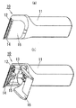
従来から、図4(a),(b)に示すような、切断した毛髪を収容する毛髪収容室15を有し、その毛髪収容室15を外部に対して開閉する蓋16を備えたヘアカッター10が提案されている(特許文献1参照)。
Conventionally, as shown in FIGS. 4A and 4B, a hair cutter having a
ヘアカッター10は、図3に示すように、本体ハウジング11と、本体ハウジング11の前端部に固定される固定刃12と、本体ハウジング11の後部に収容されるモータ13と、モータ13に駆動されて固定刃12に摺動する可動刃14と、から構成される。
As shown in FIG. 3, the
そして、本体ハウジング11の前端部には、固定刃12と可動刃14で切断された毛髪が収容される毛髪収容室15が設けてある。さらに、本体ハウジング11には、この毛髪収容室15を外部に対して開閉する蓋16が回動自在に取り付けてある。
A
上記構成のヘアカッター10は、蓋16を図3に示す位置までしか回動させることができない。そのため、毛髪収容室15を水洗いするために可動刃14が水平になるようにヘアカッター10を傾けると、蓋16が邪魔になって、水洗いがしにくいという問題があった。
The
そこで、本発明は、切断した毛髪を収容する毛髪収容室の水洗いがしやすいヘアカッターを提供することを課題とする。 Then, this invention makes it a subject to provide the hair cutter which is easy to wash with water of the hair storage chamber which accommodates the cut | disconnected hair.
上記課題を解決するための本発明のヘアカッターは、本体ハウジングと、本体ハウジングに収容されるモータと、外部に突出するように前記本体ハウジングに固定される固定刃と、前記モータに駆動されて前記固定刃に摺動する可動刃と、前記可動刃と前記固定刃で切断した毛を収容する毛髪収容室と、前記本体ハウジングの外表面に沿ってスライドして前記毛髪収容室を外部に対して開閉する蓋と、を有し、前記蓋を開いて前記毛髪収容室を外部に開放する場合に、前記可動刃の根元部に直交する仮想面に対して本体ハウジング側の領域にまで前記蓋がスライドして退避するように設け、前記蓋を前記領域にスライドさせた状態で、前記可動刃の鉛直方向に前記蓋が位置しないようにして、前記可動刃に鉛直方向から水をかけられるようにしたことを特徴とする。 The hair cutter of the present invention for solving the above problems is driven by the main body housing, a motor accommodated in the main body housing, a fixed blade fixed to the main body housing so as to protrude outward, and the motor. A movable blade that slides on the fixed blade, a hair storage chamber that stores hair cut by the movable blade and the fixed blade, and slides along the outer surface of the main body housing to move the hair storage chamber to the outside. A lid that opens and closes, and when the lid is opened to open the hair storage chamber to the outside, the lid extends to a region on the body housing side with respect to a virtual plane orthogonal to the root portion of the movable blade. So that the lid is not positioned in the vertical direction of the movable blade so that the movable blade can be sprayed with water from the vertical direction. In Characterized in that was.
また、前記毛髪収容室に、外部に連通する水抜き孔を設けることが好ましい。 Moreover, it is preferable to provide the hair accommodation chamber with a drain hole communicating with the outside.
本発明のヘアカッターは、切断した毛髪を収容する毛髪収容室の水洗いがしやすい。 The hair cutter of the present invention is easy to wash in a hair storage chamber for storing cut hair.
以下、本発明の実施形態の一例を添付図面に基づいて説明する。 Hereinafter, an example of an embodiment of the present invention will be described with reference to the accompanying drawings.
図1に示す第一の実施形態のヘアカッター1は、本体ハウジング2と、本体ハウジング2内に収容されるモータ3と、本体ハウジング2の一端に固定される固定刃5と、モータ3に駆動されて固定刃5に摺動する可動刃6と、を備える。そしてさらに、固定刃5と可動刃6で切断された毛髪が収容される毛髪収容室21と、この毛髪収容室21を外部に対して開閉する蓋8と、を備える。本実施形態のヘアカッター1は、固定刃5と可動刃6で切断した毛髪を本体ハウジング2内の毛髪収容室21に溜めながらヘアカットを行うものであり、ヘアカット後は、この毛髪収容室21を水洗い可能なものである。
A
本体ハウジング2は、片手で把持可能な筒状のものであり、その内側の一方に毛髪収容室21を備え、その内側の他方にモータ3が収容されるモータ収容室20を備える。モータ収容室20には、モータ3に電力を供給する電池等で構成される電力供給部(図示せず)も収容される。本体ハウジング2の外表面には、モータ3と電力供給部との電気的接続をオン・オフ操作する操作部7が取り付けられている。以下、図1に示すように、可動刃6及び固定刃5が水平となるようにヘアカッター1を傾けた状態を基準として、本体ハウジング2において、毛髪収容室21側を前側、モータ収容室20側を後側とし、操作部7側を上側、その反対側を下側とする。
The
操作部7は、本体ハウジング2の外表面に沿って前後方向にスライドし、一方にスライドした状態でモータ3と電力供給部との電気的接続をオンにし、他方にスライドした状態でその電気的接続をオフにする。
The operation unit 7 slides in the front-rear direction along the outer surface of the
モータ収容室20と毛髪収容室21とは、分離壁22で前後方向に区画されている。分離壁22には、モータ3のモータ軸30が貫通しており、モータ軸30の前端部分が毛髪収容室21に配置される。
The
モータ軸30の前端には、モータ軸30の軸心からずれた位置に偏心ピン32が一体に形成されている。そして、毛髪収容室21には、図2(b)に示すように、偏心ピン32に係合して往復運動する駆動力伝達部4が設けられている。
An
可動刃6及び固定刃5は、平板状の基部の端部から複数の歯が一列に並んで突出した櫛状のものである。可動刃6は、その基部に駆動力伝達部4が固定されており、モータ3の回転によって、可動刃6の歯が並ぶ方向に往復運動を行う。
The
毛髪収容室21は、本体ハウジング2の前端部分に設けられており、分離壁22と、本体ハウジング2の前端部分の両側壁24,24と、本体ハウジング2の前端部分下部のガイド壁25とで囲まれる空間である。毛髪収容室21は、図1に示すように、上方に開口26を有する。なお、ガイド壁25は、分離壁22に貫通するモータ軸30と略平行な後端部分と、その後端部分からモータ軸30の軸中心に近づく方向に向いて延びる前部分とから構成される。
The
ガイド壁25の前端部には、固定刃5の基部が固定される。固定刃5の歯部(複数の歯)は、ガイド壁25よりも前方(外部)に突出している。なお、ガイド壁25の前部分と、固定刃5の歯部は、略平行である。つまり、固定刃5の歯部が水平となるようにヘアカッター1を傾けた状態において、毛髪収容室21の底を成すガイド壁25の前部分も水平となる。この固定刃5の歯部に、可動刃6の歯部が重なり合うように可動刃6は配置されている。可動刃6は、固定刃5の歯が並ぶ方向に往復運動を行い、固定刃5に摺動する。ここで、固定刃5と可動刃6とガイド壁25の前部分とは略平行となっている。
A base portion of the
毛髪収容室21の開口26は、本体ハウジング2の上面(外表面)に取り付けられた蓋8によって、開閉される。
The opening 26 of the
蓋8は、モータ収容室20上方の本体ハウジング2の外表面と、毛髪収容室21側方の両側壁24,24の上端内面に沿って前後方向にスライドし、図2(a)に示すように、蓋8の前端部が、可動刃6の歯部の手前まで前方にスライド可能となっている。この蓋8の前端部と可動刃6の歯部の間の隙間が、ヘアカット時に切断された毛髪が入り込む隙間となっている。
The
蓋8は、最前方までスライドした状態(図2(a)の状態)で、毛髪収容室21を外部から隠す状態となる。また、蓋8は、最後方までスライドさせた状態(図2(b)の状態)で、毛髪収容室21を外部に対して最大限開放した状態となる。
The
ここで、図1に示すように、可動刃6の先端部(可動刃6の歯部)に直交する面を仮想面S1、可動刃6の根元部(可動刃6の基部)に直交する面を第二仮想面S2とする。仮想面S1と第二仮想面S2とは、互いに平行な面であり、可動刃6の摺動方向に平行であり、且つ可動刃6の歯部の突出方向に直交する仮想の面である。
Here, as shown in FIG. 1, the surface orthogonal to the tip portion of the movable blade 6 (tooth portion of the movable blade 6) is a virtual surface S1, and the surface orthogonal to the root portion of the movable blade 6 (base of the movable blade 6). Is the second virtual surface S2. The virtual surface S1 and the second virtual surface S2 are parallel to each other, are virtual surfaces that are parallel to the sliding direction of the
蓋8は、最後方にスライドした状態では、図1に示すように、仮想面S1及び第二仮想面S2と交わらない。つまり、可動刃6を水平にし、蓋8を最後方までスライドした状態で、可動刃6の先端部の鉛直方向及び可動刃6の根元部の鉛直方向には、蓋8が位置しないものとなっている。このように、蓋8は、その全体が、仮想面S1及び第二仮想面S2に対して本体ハウジング2側の領域まで退避するように設けられている。
The
そのため、本実施形態のヘアカッター1は、可動刃6を水平にし、蓋8を最後方までスライドした状態で、蓋8に邪魔されることなく、可動刃6の先端部,根元部,両側部に鉛直方向から水をかけることができるので、毛髪収容室21の水洗いがしやすいものとなっている。
Therefore, the
ここで、可動刃6の両側部は、切断後の毛くずが詰まり易い部分であるが、このように直接水を鉛直方向からかけることができるので、毛くずの除去がしやすくなっている。
Here, the both side portions of the
また、この状態で、水ではなく油を差すことも可能であるので、可動刃6の焼き付き防止を好適に行える。
Further, in this state, it is possible to insert oil instead of water, so that the
また、本実施形態のヘアカッター1は、可動刃6が水平になるようにヘアカッター1を傾けた状態で、開口26を通じて、可動刃6を鉛直方向に開放させることができる。
Moreover, the
一方、図1に示すように、蓋8を最後方までスライドさせた状態では、蓋8の裏面80の略全体は、モータ収容室20上方の本体ハウジング2の外表面に重なる。この状態で、蓋8の前端部分は、毛髪収容室21の開口26に位置する。しかし、毛髪収容室21の開口26の後方部分には、蓋8の前端部分の裏面80を毛髪収容室21に対して覆う遮蔽部27が設けてある。そのため、この最後方までスライドさせた状態で、蓋8は、その裏面80の全体又は略全体が、毛髪収容室21に対して覆われた状態となる。
On the other hand, as shown in FIG. 1, in the state where the
このような構成とすることで、本実施形態のヘアカッター1は、蓋8を開いて毛髪収容室21の水洗いを行っても、蓋8の裏面80には水洗いの水が当たり難い。そのため、本実施形態のヘアカッター1は、水洗いが終わって蓋8を閉じても、蓋8に付着した水分が毛髪収容室21に滴下することが少ないので、カビ等の発生を抑制できるものとなっている。
With such a configuration, even when the
ところで、図示はしていないが、毛髪収容室21には、外部に連通する水抜き孔を設けることが好適である。つまり、ガイド壁25や、両側壁24,24の下部に水抜き孔を設けることが好適である。このような構成とすれば、可動刃6を水平にし、蓋8を最後方までスライドした状態で、毛髪収容室21の下部部分に水抜き孔ができる。よって、毛髪収容室21に溜まった毛くずを水洗いする場合、水及び毛くずの流れがスムースになり、毛くずを流出させ易くなる。
By the way, although not shown, it is preferable that the
また、ヘアカッター1は、蓋8を開いて毛髪収容室21を外部に開放する場合に可動刃6を固定刃5から離す機構を備えることも好適である。このようにすれば、水洗いの際に蓋8を開いて、固定刃5と可動刃6の間に隙間を確保することができ、可動刃6と固定刃5の間に挟まった毛くずも容易に洗い流すことができる。
The
また、蓋8を閉じて毛髪収容室21を外部から隠した場合に、モータ3を駆動可能とし、蓋8を開いて毛髪収容室21を外部に開放する場合に、モータ3を停止する機構を設けることが好適である。また、モータ3を駆動した場合に、蓋8を閉じて毛髪収容室21を外部に開放不可とし、モータ3を停止した場合に、蓋8を開いて毛髪収容室21を外部に開放可能とする機構を設けることも好適である。これらの機構を設ければ、ヘアカット時に、切断前の毛髪が毛髪収容室21の中に入ってモータ3や可動刃6に巻き込まれてしまうことを抑制することができる。
Further, when the
また、操作部7には、オン・オフ以外に、モータ3を低速で回転させる洗浄モードを設けることが好適である。このようにすれば、毛髪収容室21を水洗いする際に、モータ3を低速で回転させて、より水洗い性能を向上させることができる。
The operation unit 7 is preferably provided with a cleaning mode for rotating the
上述した構成のヘアカッター1を使用方法の一例について説明する。
An example of how to use the
まず、毛髪収容室21の開口26を蓋8で閉じる。続いて、操作部7をオン操作してモータ3に電力を供給し、可動刃6を駆動させる。そして、ガイド壁25を頭に沿わせて刈り上げていく。この時、可動刃6と固定刃5で挟まれて切断された毛髪が毛髪収容室21に収容される。刈り上げが終了したら、操作部7をオフ操作してモータ3を停止する。そして、蓋8を開いて、毛髪収容室21を外部に対して開放状態とする。そして、可動刃6が水平となるようにヘアカッター1を傾けて、鉛直方向から水をかけ、可動刃6,固定刃5および毛髪収容室21を水洗いする。
First, the
続いて、本発明の第二の実施形態のヘアカッター1について説明する。上述した第一の実施形態のヘアカッター1の構成と同じ構成については説明を省略し、異なる構成についてのみ詳しく説明する。図面については、第一の実施形態のヘアカッター1の図1,図2(a),図2(b)を参照されたい。
Then, the
本実施形態のヘアカッター1は、蓋8が、本体ハウジング2にスライド自在ではなく、着脱自在に取り付けられる。
In the
つまり、毛髪収容室21を外部に開放する場合には、蓋8を外すことで、仮想面S1及び第二仮想面S2に対して本体ハウジング2側の領域にまで蓋8を退避可能とする。
That is, when the
このような構成とすることで、蓋8を退避させれば、可動刃6を水平にした状態で、可動刃6の先端部,根元部,両側部に鉛直方向から水をかけることができる。また、蓋8を取り外して、蓋8と本体ハウジング2の間に詰まった毛くずを取り除くことも容易にできる。また、取り外した蓋8の裏面80を、水洗いすることもできる。以上のように、本実施形態のヘアカッター1は、毛髪収容室21の水洗いがしやすく、毛くずの除去がしやすいヘアカッター1となっている。
With such a configuration, if the
続いて、本発明の第三の実施形態のヘアカッター1について説明する。上述した第一の実施形態のヘアカッター1の構成と同じ構成については説明を省略し、異なる構成についてのみ詳しく説明する。図面については、第一の実施形態のヘアカッター1の図1,図2(a),図2(b)を参照されたい。
Then, the
本実施形態のヘアカッター1では、蓋8が本体ハウジング2に回動自在に取り付けられる。その蓋8は、毛髪収容室21を外部に開放する場合に、仮想面S1及び第二仮想面S2に対して本体ハウジング2側の領域にまで退避可能とする。
In the
このような構成とすることで、蓋8全体を、第二仮想面S2よりも本体ハウジング2側の領域に退避させれば、可動刃6を水平にした状態で、可動刃6の先端部,根元部に鉛直方向から水をかけることができる。以上のように、本実施形態のヘアカッター1も、毛髪収容室21の水洗いがしやすく、毛くずの除去がしやすいヘアカッター1となっている。
With such a configuration, if the
以上本発明の第一乃至第三の実施形態に示すヘアカッター1は、本体ハウジング2と、本体ハウジング2に収容されるモータ3と、外部に突出するように本体ハウジング2に固定される固定刃5と、モータ3に駆動されて固定刃5に摺動する可動刃6と、を有する。そして、可動刃6と固定刃5で切断した毛を収容する毛髪収容室21と、毛髪収容室21を外部に対して開閉する蓋8と、を有する。さらに、蓋8を開いて毛髪収容室21を外部に開放する場合に、可動刃6の先端部に直交する仮想面S1に対して本体ハウジング2側の領域にまで蓋8が退避するように設けたものである。
As described above, the
このような構成とすることで、蓋8を開いて毛髪収容室21を外部に開放する場合に、可動刃6の先端部に直交する仮想面S1に対して本体ハウジング2側の領域にまで蓋8を退避できる。そのため、可動刃6を水平にし、蓋8を最後方までスライドした状態で、蓋8に邪魔されることなく、可動刃6の先端部に鉛直方向から水をかけることができるので、本発明の実施形態のヘアカッター1は、毛髪収容室21の水洗いがしやすいものとなっている。
With such a configuration, when the
以上、本発明を添付図面に示す実施形態に基づいて説明したが、本発明は上記の各実施形態に限定されるものではなく、本発明の意図する範囲内であれば、適宜の設計変更が可能である。 Although the present invention has been described based on the embodiments shown in the accompanying drawings, the present invention is not limited to the above-described embodiments, and appropriate design changes can be made within the intended scope of the present invention. Is possible.
1 ヘアカッター
2 本体ハウジング
21 毛髪収容室
27 遮蔽部
3 モータ
5 固定刃
6 可動刃
8 蓋
80 裏面
S1 仮想面
S2 第二仮想面
DESCRIPTION OF
Claims (2)
前記蓋を開いて前記毛髪収容室を外部に開放する場合に、前記可動刃の根元部に直交する仮想面に対して本体ハウジング側の領域にまで前記蓋がスライドして退避するように設け、
前記蓋を前記領域にスライドさせた状態で、前記可動刃の鉛直方向に前記蓋が位置しないようにして、前記可動刃に鉛直方向から水をかけられるようにしたことを特徴とするヘアカッター。 A main body housing; a motor housed in the main body housing; a fixed blade fixed to the main body housing so as to protrude outward; a movable blade driven by the motor to slide on the fixed blade; and the movable blade A hair storage chamber for storing hair cut by the fixed blade, and a lid that slides along the outer surface of the main body housing to open and close the hair storage chamber with respect to the outside,
When the lid is opened to open the hair storage chamber to the outside, the lid is slid and retracted to a region on the main body housing side with respect to a virtual plane orthogonal to the root portion of the movable blade ,
A hair cutter characterized in that , with the lid slid into the region, the lid is not positioned in the vertical direction of the movable blade so that water can be applied to the movable blade from the vertical direction .
Priority Applications (3)
| Application Number | Priority Date | Filing Date | Title |
|---|---|---|---|
| JP2010216223A JP5572048B2 (en) | 2010-09-27 | 2010-09-27 | Hair cutter |
| EP20110180423 EP2433764B1 (en) | 2010-09-27 | 2011-09-07 | Hair cutter |
| CN201110290275.XA CN102416631B (en) | 2010-09-27 | 2011-09-19 | Hair cutter |
Applications Claiming Priority (1)
| Application Number | Priority Date | Filing Date | Title |
|---|---|---|---|
| JP2010216223A JP5572048B2 (en) | 2010-09-27 | 2010-09-27 | Hair cutter |
Publications (2)
| Publication Number | Publication Date |
|---|---|
| JP2012070803A JP2012070803A (en) | 2012-04-12 |
| JP5572048B2 true JP5572048B2 (en) | 2014-08-13 |
Family
ID=44587730
Family Applications (1)
| Application Number | Title | Priority Date | Filing Date |
|---|---|---|---|
| JP2010216223A Active JP5572048B2 (en) | 2010-09-27 | 2010-09-27 | Hair cutter |
Country Status (3)
| Country | Link |
|---|---|
| EP (1) | EP2433764B1 (en) |
| JP (1) | JP5572048B2 (en) |
| CN (1) | CN102416631B (en) |
Families Citing this family (4)
| Publication number | Priority date | Publication date | Assignee | Title |
|---|---|---|---|---|
| WO2015134580A1 (en) * | 2014-03-04 | 2015-09-11 | Spectrum Brands, Inc. | Electric hair trimmer |
| EP3103600A1 (en) | 2015-06-08 | 2016-12-14 | BaByliss Faco sprl | Beard trimmer with one or more rotating heads surrounded by combs with particular geometry and equipped with a protection position for the comb |
| ES2909897T3 (en) * | 2015-11-18 | 2022-05-10 | Babyliss FACO SRL | Trimmer with hair catcher |
| EP3685973A1 (en) * | 2019-01-23 | 2020-07-29 | Koninklijke Philips N.V. | Comb attachment and hair cutting appliance |
Family Cites Families (16)
| Publication number | Priority date | Publication date | Assignee | Title |
|---|---|---|---|---|
| NL7404738A (en) * | 1974-04-08 | 1975-10-10 | Philips Nv | ELECTRIC HAIR CLIPPER. |
| JPS57166876U (en) * | 1981-04-17 | 1982-10-21 | ||
| JPS597906A (en) | 1982-07-07 | 1984-01-17 | Mitsubishi Rayon Co Ltd | Optical transmission fiber |
| JPS59200681A (en) * | 1983-04-28 | 1984-11-14 | 松下電工株式会社 | Electric razor |
| JPS61149193A (en) * | 1984-12-25 | 1986-07-07 | 松下電工株式会社 | Hair cutter |
| JPH0337585Y2 (en) * | 1985-05-25 | 1991-08-08 | ||
| US4694575A (en) * | 1986-08-25 | 1987-09-22 | Boerger Daniel A | Clipper attachment device |
| JPH0817861B2 (en) * | 1987-05-15 | 1996-02-28 | 松下電工株式会社 | Electric razor protective cap |
| CN2188466Y (en) * | 1994-04-26 | 1995-02-01 | 贺世春 | Motor driving hair clippers |
| US6076263A (en) * | 1997-07-17 | 2000-06-20 | Andis Company | Hair clipper with resiliently removable cover portion enclosing a blade drive assembly |
| US20080250645A1 (en) * | 2005-10-06 | 2008-10-16 | Tringali Richard J | Hair Clipper with Light Source |
| JP4462162B2 (en) * | 2005-10-11 | 2010-05-12 | パナソニック電工株式会社 | Hair cutter |
| JP4613785B2 (en) * | 2005-10-11 | 2011-01-19 | パナソニック電工株式会社 | Hair cutter |
| JP4613948B2 (en) * | 2007-12-25 | 2011-01-19 | パナソニック電工株式会社 | Electric hair remover |
| JP2009201715A (en) * | 2008-02-28 | 2009-09-10 | Sanyo Electric Co Ltd | Electric shaver |
| AT10839U1 (en) * | 2008-10-16 | 2009-11-15 | Payer Int Technologies Gmbh | HAIR CUTTER |
-
2010
- 2010-09-27 JP JP2010216223A patent/JP5572048B2/en active Active
-
2011
- 2011-09-07 EP EP20110180423 patent/EP2433764B1/en active Active
- 2011-09-19 CN CN201110290275.XA patent/CN102416631B/en active Active
Also Published As
| Publication number | Publication date |
|---|---|
| EP2433764A1 (en) | 2012-03-28 |
| CN102416631B (en) | 2014-07-16 |
| JP2012070803A (en) | 2012-04-12 |
| CN102416631A (en) | 2012-04-18 |
| EP2433764B1 (en) | 2013-10-23 |
Similar Documents
| Publication | Publication Date | Title |
|---|---|---|
| JP5572048B2 (en) | Hair cutter | |
| US20170311767A1 (en) | Roller brush assembly | |
| CN110340947A (en) | Electric hair trimmer | |
| US20110067241A1 (en) | Nose hair trimmer | |
| EP2298511A1 (en) | Nose hair trimmer | |
| KR20120129908A (en) | Motorized shaving apparatus head and shaving apparatus implementing the same | |
| JP5520179B2 (en) | Hair cutter | |
| US20190290085A1 (en) | Vacuum cleaner | |
| CN205521525U (en) | Electric razor | |
| US4116099A (en) | Household appliance driven by an electric motor, especially slicing machine for foods | |
| WO2013015034A1 (en) | Blade-protecting cap and electric razor to which said blade-protecting cap is installed | |
| WO2018059538A1 (en) | Accessory for washing shoe and shoe washing means | |
| WO2012091166A1 (en) | Combined-use tooth brush and electric interdental brush | |
| JP2009028434A (en) | Cleaner for electric razor | |
| JP4492829B2 (en) | Electric razor | |
| JP7088484B2 (en) | washing machine | |
| CN218285632U (en) | Integrated hair trimming device convenient to use and clean | |
| JP6481985B2 (en) | Electric razor | |
| CN214179486U (en) | Multifunctional nail clippers | |
| JP5903651B2 (en) | Electric razor | |
| CN217536398U (en) | Hair bulb trimmer | |
| CN210408169U (en) | Food processor | |
| CN212394794U (en) | Dust suction head | |
| JP6760730B2 (en) | Toilet bowl cleaning tank | |
| JPH0446158B2 (en) |
Legal Events
| Date | Code | Title | Description |
|---|---|---|---|
| A711 | Notification of change in applicant |
Free format text: JAPANESE INTERMEDIATE CODE: A712 Effective date: 20120118 |
|
| A621 | Written request for application examination |
Free format text: JAPANESE INTERMEDIATE CODE: A621 Effective date: 20130201 |
|
| A131 | Notification of reasons for refusal |
Free format text: JAPANESE INTERMEDIATE CODE: A131 Effective date: 20140128 |
|
| A977 | Report on retrieval |
Free format text: JAPANESE INTERMEDIATE CODE: A971007 Effective date: 20140130 |
|
| A977 | Report on retrieval |
Free format text: JAPANESE INTERMEDIATE CODE: A971007 Effective date: 20140320 |
|
| A521 | Written amendment |
Free format text: JAPANESE INTERMEDIATE CODE: A523 Effective date: 20140331 |
|
| TRDD | Decision of grant or rejection written | ||
| A01 | Written decision to grant a patent or to grant a registration (utility model) |
Free format text: JAPANESE INTERMEDIATE CODE: A01 Effective date: 20140603 |
|
| A61 | First payment of annual fees (during grant procedure) |
Free format text: JAPANESE INTERMEDIATE CODE: A61 Effective date: 20140627 |
|
| R151 | Written notification of patent or utility model registration |
Ref document number: 5572048 Country of ref document: JP Free format text: JAPANESE INTERMEDIATE CODE: R151 |