JP5571668B2 - Intraocular lens and pre-loaded cassette for lens injection system - Google Patents
Intraocular lens and pre-loaded cassette for lens injection system Download PDFInfo
- Publication number
- JP5571668B2 JP5571668B2 JP2011527172A JP2011527172A JP5571668B2 JP 5571668 B2 JP5571668 B2 JP 5571668B2 JP 2011527172 A JP2011527172 A JP 2011527172A JP 2011527172 A JP2011527172 A JP 2011527172A JP 5571668 B2 JP5571668 B2 JP 5571668B2
- Authority
- JP
- Japan
- Prior art keywords
- cassette
- injector
- lid
- cassette body
- coupling means
- Prior art date
- Legal status (The legal status is an assumption and is not a legal conclusion. Google has not performed a legal analysis and makes no representation as to the accuracy of the status listed.)
- Active
Links
Images


Classifications
-
- A—HUMAN NECESSITIES
- A61—MEDICAL OR VETERINARY SCIENCE; HYGIENE
- A61F—FILTERS IMPLANTABLE INTO BLOOD VESSELS; PROSTHESES; DEVICES PROVIDING PATENCY TO, OR PREVENTING COLLAPSING OF, TUBULAR STRUCTURES OF THE BODY, e.g. STENTS; ORTHOPAEDIC, NURSING OR CONTRACEPTIVE DEVICES; FOMENTATION; TREATMENT OR PROTECTION OF EYES OR EARS; BANDAGES, DRESSINGS OR ABSORBENT PADS; FIRST-AID KITS
- A61F2/00—Filters implantable into blood vessels; Prostheses, i.e. artificial substitutes or replacements for parts of the body; Appliances for connecting them with the body; Devices providing patency to, or preventing collapsing of, tubular structures of the body, e.g. stents
- A61F2/02—Prostheses implantable into the body
- A61F2/14—Eye parts, e.g. lenses, corneal implants; Implanting instruments specially adapted therefor; Artificial eyes
- A61F2/16—Intraocular lenses
- A61F2/1691—Packages or dispensers for intraocular lenses
-
- A—HUMAN NECESSITIES
- A61—MEDICAL OR VETERINARY SCIENCE; HYGIENE
- A61F—FILTERS IMPLANTABLE INTO BLOOD VESSELS; PROSTHESES; DEVICES PROVIDING PATENCY TO, OR PREVENTING COLLAPSING OF, TUBULAR STRUCTURES OF THE BODY, e.g. STENTS; ORTHOPAEDIC, NURSING OR CONTRACEPTIVE DEVICES; FOMENTATION; TREATMENT OR PROTECTION OF EYES OR EARS; BANDAGES, DRESSINGS OR ABSORBENT PADS; FIRST-AID KITS
- A61F2/00—Filters implantable into blood vessels; Prostheses, i.e. artificial substitutes or replacements for parts of the body; Appliances for connecting them with the body; Devices providing patency to, or preventing collapsing of, tubular structures of the body, e.g. stents
- A61F2/02—Prostheses implantable into the body
- A61F2/14—Eye parts, e.g. lenses, corneal implants; Implanting instruments specially adapted therefor; Artificial eyes
- A61F2/16—Intraocular lenses
- A61F2/1662—Instruments for inserting intraocular lenses into the eye
- A61F2/1678—Instruments for inserting intraocular lenses into the eye with a separate cartridge or other lens setting part for storage of a lens, e.g. preloadable for shipping
Description
本発明は、請求項1のプレアンブルに記載のカセットに関し、更に請求項10のプレアンブルに記載の挿入システムに関する。 The invention relates to a cassette according to the preamble of claim 1 and further to an insertion system according to the preamble of claim 10.
現在、白内障手術において、眼球内レンズ(IOL)として知られる人工レンズは、眼の水晶体嚢に標準的にインプラント処理(挿入)される。手術中、通常2〜4mmの眼球切開が形成され、ここを通って生来の眼のレンズが取り出されてインプラントと交換される。生来の眼のレンズを取り出すためには、最初に超音波で生来の眼のレンズを破壊し、次いで切開により取り出される。生来の眼のレンズを取り出した後、人工レンズは、折り畳んだ状態で切開を通して水晶体嚢に導入する。折り畳みレンズが水晶体嚢に導入されるとすぐに、レンズは元の形状に開かれる。 Currently, in cataract surgery, artificial lenses known as intraocular lenses (IOLs) are typically implanted (inserted) into the lens capsule of the eye. During surgery, a 2-4 mm ocular incision is usually made, through which the native eye lens is removed and replaced with an implant. To remove the natural eye lens, the natural eye lens is first destroyed with ultrasound and then removed by incision. After removing the natural eye lens, the artificial lens is folded and introduced into the capsular bag through an incision. As soon as the folding lens is introduced into the capsular bag, the lens is opened to its original shape.
手術ツール及びインプラントの改善によって、手術者は、切開をこれまでよりも小さくすることが可能になる。現在では、生来の眼のレンズは、約2mmの切開でさえこれを通して取り出すことができる。しかしながら、このことは、同じ切開を通して眼球内レンズを挿入できる場合にだけ意味がある。 Improvements in surgical tools and implants allow surgeons to make incisions smaller than ever. At present, the native eye lens can be removed through even an incision of about 2 mm. However, this is only meaningful if the intraocular lens can be inserted through the same incision.
眼球内レンズの挿入において、レンズを装填することができ、次いで、インジェクタを用いてレンズが送出できカートリッジが近年開発されてきた。このタイプのカートリッジ及びインジェクタの実施例は、米国特許第4,681,102号,第5,582,614号、第5,947,975号、及び米国特許出願公開第2004/0199174号により周知である。 In insertion of an intraocular lens, the lens can be loaded and then the lens can be delivered using an injector and cartridges have been developed in recent years. Examples of this type of cartridge and injector are well known from U.S. Pat. Nos. 4,681,102, 5,582,614, 5,947,975, and U.S. Patent Application Publication No. 2004/0199174. is there.
米国特許第第4,681,102号によるインジェクタ装置では、レンズを折り畳む装置として具現化されるカートリッジとインジェクタノズルとは別個の部品である。カートリッジは、インジェクタハウジング内に挿入することができ、その結果、インジェクタノズルをインジェクタハウジングの正面にネジ止めすることができる。 In the injector device according to U.S. Pat. No. 4,681,102, the cartridge embodied as a lens folding device and the injector nozzle are separate parts. The cartridge can be inserted into the injector housing so that the injector nozzle can be screwed to the front of the injector housing.
米国特許第5,582,614号によるインジェクタ装置及び最近の周知のインジェクタ装置では、カートリッジは、折り畳み装置及びインジェクタノズルの一体部品から構成される。 In the injector device according to US Pat. No. 5,582,614 and recently known injector devices, the cartridge is composed of an integral part of the folding device and the injector nozzle.
米国特許出願公開第2004/0199174号は、図2において、インジェクタハウジングがピストンを受けるシリンダ、レンズ折り畳み装置、及びインジェクタノズルの一体部品から構成される。 In US Patent Application Publication No. 2004/0199174, in FIG. 2, an injector housing is composed of a cylinder that receives a piston, a lens folding device, and an integral part of an injector nozzle.
最も一般的に使用されている眼球内レンズは、親水性材料から作られる。このタイプのレンズは、製造業者により滅菌状態にパックされた液体浴内で配送される。 The most commonly used intraocular lens is made from a hydrophilic material. This type of lens is delivered in a liquid bath packed sterile by the manufacturer.
液体中での保管は、レンズが完全に乾燥するのを防ぐ必要がある。手術中、レンズがパッケージから取り出され、カートリッジに挿入しなくてはならず、その結果、次いで、カートリッジをインジェクタに装填することができる。これらは極めて小さい弾性構造であるので、カートリッジを取り付けている間、レンズが折り畳み中に落ち又は飛び出し、従って滅菌を失う一定のリスクがある。 Storage in liquid should prevent the lens from drying out. During surgery, the lens must be removed from the package and inserted into the cartridge so that the cartridge can then be loaded into the injector. Since these are very small elastic structures, there is a certain risk that the lens will fall or pop out during folding and thus lose sterility while the cartridge is installed.
米国特許出願公開第2005/0049605号は、インジェクタ本体と、該インジェクタ本体に隣接したインジェクタノズルとを備えた装填済み注入装置を開示している。インジェクタノズルは、インジェクタ本体に隣接してIOLを受ける役割を果たすアパーチャを有する。IOLは、応力を受けていない状態では、上方から挿入できる取付具によりアパーチャ内に保持される。相互に分離するガイド要素がアパーチャの片側で該アパーチャ上に側方にモールド成形される。ガイド要素は、注入装置の長手方向の延長部に垂直に変位可能な可動圧縮負荷を受けるよう機能する。圧縮負荷を用いてIOLを圧縮し、取付具が取り外されると、注入の準備が整った状態になることができる。第2005/0049605号の注入装置は、製造業者によりIOLが既に装填されており、滅菌パッケージ内に送出されている。第2005/0049605号の注入装置の利点は、IOLは既に注入装置に挿入されており、手術者が直接把持する必要がもはやないことである。それでも尚、この注入装置の欠点は、レンズは液体中に保管することができないので、この装置は疎水性のレンズにのみ好適であることである。 U.S. Patent Application Publication No. 2005/0049605 discloses a pre-filled infusion device comprising an injector body and an injector nozzle adjacent to the injector body. The injector nozzle has an aperture that receives an IOL adjacent to the injector body. The IOL is held in the aperture by a fitting that can be inserted from above when not subjected to stress. Guide elements that are separated from one another are molded laterally on the aperture on one side of the aperture. The guide element functions to receive a movable compressive load that is displaceable perpendicular to the longitudinal extension of the injection device. Once the IOL is compressed using a compression load and the fitting is removed, it can be ready for injection. The 2005/0049605 infusion device is already loaded with an IOL by the manufacturer and delivered in a sterile package. The advantage of the 2005/0049605 infusion device is that the IOL has already been inserted into the infusion device and the operator no longer needs to grasp it directly. Nevertheless, the disadvantage of this injection device is that it is only suitable for hydrophobic lenses, since the lens cannot be stored in liquid.
米国特許出願公開第2007/0060925は、親水性レンズの予装填も可能にするシステムを開示している。この事例では、システムは遠位部と近位部とに分割される。遠位部は、この事例ではレンズ(IOL)、レンズコンテナ、及びカートリッジを包含し、滅菌され、液体で充填された追加の気密シールされたコンテナ内に共に保管される。コンテナが開放されると、遠位部及び近位部は、作業員が組み立てなければならない。コンテナ(バイアル)において組み立てた形態でも近位及び遠位部を滅菌できる可能性についても言及されているが、これには極めて大きなコンテナと大量の液体が必要とされる。この提案の解決策の欠点は、コンテナを開いたときに液体が流出することが含まれる。このタイプのシステムは、そのサイズを考慮すると扱いにくく、特に顧客の立場を考えたものではない。 US Patent Application Publication No. 2007/0060925 discloses a system that also allows pre-loading of hydrophilic lenses. In this case, the system is divided into a distal part and a proximal part. The distal portion, in this case, includes a lens (IOL), lens container, and cartridge, and is stored together in an additional hermetically sealed container that is sterilized and filled with liquid. Once the container is opened, the distal and proximal parts must be assembled by the operator. Although mention is made of the possibility of sterilizing the proximal and distal parts in assembled form in a container (vial), this requires a very large container and a large amount of liquid. Disadvantages of this proposed solution include liquid spilling when the container is opened. This type of system is cumbersome in view of its size and is not specifically designed for customers.
柔軟な眼球内レンズ(IOL)用のカセット及びインジェクタは、WO03/049645から周知である。カセットは、ベース部と、該ベース部に連接されたリッドとから構成される。レンズを受ける役割を果たす中空スペースは、リッド及びベース部内に形成される。入口開口及び出口開口及び出口開口は、カセットの相互に対向する側部に設けられる。プランジャが入口開口を通ってカセット内に導入され、レンズを出口開口に通して排出するようにする。インジェクタ上の対応する部品と相互作用する役目を果たす突起が、ベース部上及びリッド上に設けられる。WO03/049645のカセットはまた、親水性レンズを受けるのに好適である。この事例では、レンズを内部に受けるカセットは、液体が充填される気密シール可能コンテナ内に置かれ、コンテナ内で滅菌される。作業員によりコンテナが開放されると、カセットはインジェクタ内に挿入される。或いは、予めインジェクタ上にカセットを取り付け、液体が充填されたコンテナ内でインジェクタ全体を気密シールすることが提案されている。しかしながら、これも同様に大型のコンテナを必要とし、ユーザにとって好都合ではない。 A cassette and injector for a flexible intraocular lens (IOL) are known from WO 03/049645. The cassette includes a base portion and a lid connected to the base portion. A hollow space that serves to receive the lens is formed in the lid and the base. The inlet opening, the outlet opening and the outlet opening are provided on opposite sides of the cassette. A plunger is introduced into the cassette through the inlet opening, allowing the lens to exit through the outlet opening. Protrusions are provided on the base and on the lid which serve to interact with corresponding parts on the injector. The cassette of WO 03/049645 is also suitable for receiving hydrophilic lenses. In this case, the cassette that receives the lens inside is placed in a hermetically sealable container filled with liquid and sterilized in the container. When the container is opened by the operator, the cassette is inserted into the injector. Alternatively, it has been proposed to mount a cassette on the injector in advance and hermetically seal the entire injector in a container filled with liquid. However, this also requires a large container and is not convenient for the user.
米国特許出願公開第2002/0077633は、インジェクタ及びカセットを備えた変形可能眼球内レンズ用のインプラントシステムを開示している。カセットは、カセット下側部分とカセット上側部分とから構成され、これらは共に接合されてレンズを受けるためのスペースを定める。カセットは、相互に対向する側部において、インジェクタのピストンが貫通できる開口を有する。インジェクタ上の凹部に収まる突起は、カセット下側部分の底部にある。カセットがインジェクタに装填された場合、該カセットは正確に位置決めされ、開口は変位可能ピストンと同軸である。 US 2002/0077633 discloses an implant system for a deformable intraocular lens comprising an injector and a cassette. The cassette is composed of a cassette lower portion and a cassette upper portion, which are joined together to define a space for receiving a lens. The cassette has openings through which the pistons of the injectors can pass through on opposite sides. A protrusion that fits into a recess on the injector is at the bottom of the lower portion of the cassette. When the cassette is loaded into the injector, the cassette is accurately positioned and the opening is coaxial with the displaceable piston.
上記で説明された全てのカセットは、インジェクタピストンの通過及びレンズの送出のために開口が閉鎖されていない点で共通している。従って、液体内に保管されなければならないレンズの保管は、全ての事例において、液体が充填され且つカセットが気密シールされた状態で保管できる別のコンテナを必要とする。 All the cassettes described above are common in that the opening is not closed for the passage of the injector piston and the delivery of the lens. Accordingly, storage of lenses that must be stored in liquid requires, in all cases, a separate container that can be stored with the liquid filled and the cassette hermetically sealed.
上記で説明したように、親水性IOLが既に予装填されているカセットは、商業的に入手可能である。インジェクタは、インジェクタノズルの前に、カセットが挿入される挿入容器を有する。カセットは、保管液体共にコンテナから取り出され(湿潤パッケージ)、インジェクタに挿入される。輸送中にカセットないでIOLが滑るのを防ぐために、カセットは相互連結装置を備える。カセットがインジェクタの挿入装置内にあると直ぐに、相互連結が破断し、IOLが放出されて眼に注入される。IOLを保護するカセット内で該IOLがインジェクタに移送されることが有利である。それでも尚、カセットの欠点は、これが極めて小型で、その結果2つの指を用いて把持するのが困難なことである。別の欠点は、IOLがパッケージから取り出され、インジェクタピストンを導入し且つIOLを排出する役割を果たすカセットの開口を介してインジェクタ内に固定されるまでに外部環境と直接接触することである。従って、カセットを偶発的に落下させてしまうと、IOLが使用できなくなる可能性がある。 As explained above, cassettes that are pre-loaded with hydrophilic IOLs are commercially available. The injector has an insertion container into which the cassette is inserted before the injector nozzle. The cassette is removed from the container with the storage liquid (wet package) and inserted into the injector. In order to prevent the IOL from slipping without the cassette during transport, the cassette is provided with an interconnection device. As soon as the cassette is in the injector insertion device, the interconnection breaks and the IOL is released and injected into the eye. Advantageously, the IOL is transferred to the injector in a cassette that protects the IOL. Nevertheless, the disadvantage of the cassette is that it is very small and as a result is difficult to grasp with two fingers. Another disadvantage is that the IOL is in direct contact with the external environment before it is removed from the package and secured in the injector through the opening of the cassette which serves to introduce the injector piston and eject the IOL. Therefore, if the cassette is accidentally dropped, the IOL may not be usable.
従って、本発明の目的は、IOLの外科的使用中に必要な所要の手動介入の回数を最小限にするカセット並びにカセット及びインジェクタから構成されるインジェクタシステムを提案することである。別の目的は、特に液体中に保管されるレンズを製造中にできるだけ迅速に装置に装填でき、装填後に手術までカセット無しで、この事例では追加の湿潤コンテナ内に保管されなければならないインジェクタ全体を確実に位置決めしたままにする方法に関する手段を開示している。 Accordingly, it is an object of the present invention to propose a cassette and an injector system consisting of a cassette and an injector that minimizes the number of required manual interventions required during surgical use of the IOL. Another object is that the lens, which is stored in liquid, can be loaded into the device as quickly as possible during production, without the cassette until the operation after loading, in this case the entire injector which has to be stored in an additional wet container Means are disclosed relating to a method of remaining securely positioned.
本発明によれば、最初に述べたタイプのカセットにおいて、これは、カセットが閉鎖されたときに前記カセットリッドが受入スペース及び開口を閉鎖する点で達成される。本発明によるカセットは、カセットリッドが外部環境から受入スペースを気密シールするので、親水性レンズがカセット内で直接滅菌され、比較的長時間保管することができるという、従来使用していたカセットよりも優れた利点を有する。次いで、カセットは、滅菌の前に注入装置に挿入されて、該注入装置共に滅菌した後、使用できる状態にすることができる。或いは、カセットはまた、注入装置とは別個に滅菌し、レンズのインプラントの直前に注入装置に挿入してもよい。この2つの手順は、手術者がレンズを把持すること、又は他の手動の装填動作を実施することが必要ではないという利点がある。レンズは、カセット内で予め滅菌されるのが好ましい。この目的において、カセットは、120℃を上回るIOL要求温度の滅菌に好適な生体適合性プラスチック材料から作られるのが好ましい。 According to the invention, in the cassette of the type first mentioned, this is achieved in that the cassette lid closes the receiving space and opening when the cassette is closed. In the cassette according to the present invention, since the cassette lid hermetically seals the receiving space from the external environment, the hydrophilic lens is directly sterilized in the cassette and can be stored for a relatively long time, compared to the cassette used in the past. Has excellent advantages. The cassette can then be inserted into the infusion device before sterilization and ready for use after sterilization with the infusion device. Alternatively, the cassette may also be sterilized separately from the injection device and inserted into the injection device immediately before the lens implant. The two procedures have the advantage that the surgeon does not need to grip the lens or perform other manual loading operations. The lens is preferably pre-sterilized in the cassette. For this purpose, the cassette is preferably made from a biocompatible plastic material suitable for sterilization at IOL requirements above 120 ° C.
好ましくは、カセットリッドの縁部とカセット本体との間にシールが設けられる。シールは、受入スペースの外部環境からの確実なシール処理を保証する。原理的には、カセットリッド及びカセット本体は異なる形態を有することができる。しかしながら、リッドがカセット本体の開口をシールできることは重要である。原理的には、リッドは、1、2、又は複数の部品で設計することができる。有利には、カセット本体は、嵌合的にカセットリッド内に少なくとも部分的に受けられる。好都合には、シールは、カセット本体のハウジング外周にある周辺溝に構成される。 Preferably, a seal is provided between the edge of the cassette lid and the cassette body. The seal ensures a reliable sealing process from the outside environment of the receiving space. In principle, the cassette lid and the cassette body can have different forms. However, it is important that the lid can seal the opening in the cassette body. In principle, the lid can be designed with one, two or several parts. Advantageously, the cassette body is at least partially received in the cassette lid in a mating manner. Conveniently, the seal is configured in a peripheral groove on the outer periphery of the housing of the cassette body.
有利には、カセットの第1の結合手段は、インジェクタの第2の結合手段と回転可能に相互作用する。これらの結合手段は、異なるように構成することができる。好ましい実施形態において、第1の結合手段はジャーナルにより形成することができ、第2の結合手段は、ジャーナル容器により形成することができ、或いはその逆であってもよい。有利な実施形態によれば、例えば、突起又はアンダーカット及び相互作用するロック位置の形態の相互に作用するロック手段はまた、カセット及びインジェクタ上に設けられる。ロック手段は、該カセットがインジェクタに挿入されたときに、カセット及びインジェクタが破壊することなく互いに分離可能にされるのを防ぐのが好ましい。 Advantageously, the first coupling means of the cassette interacts rotatably with the second coupling means of the injector. These coupling means can be configured differently. In a preferred embodiment, the first coupling means can be formed by a journal and the second coupling means can be formed by a journal container, or vice versa. According to an advantageous embodiment, interacting locking means, for example in the form of protrusions or undercuts and interacting locking positions, are also provided on the cassette and the injector. The locking means preferably prevents the cassette and injector from being separable from each other without breaking when the cassette is inserted into the injector.
有利には、カセット本体は、カセットリッドがカセットの閉鎖状態で載ってシールを形成することができる周辺シール縁部を外部に有する。好都合には、カセットリッド及びカセット本体を共に解除可能に接合するために、カセットリッド及びカセット本体上に相互連結手段が設けられる。好ましくは、これらの相互連結手段は、相互に対向する側部でカセット本体と相互作用することができる枢動レバーとして設計される。枢動レバーは、この事例では、カセットリッドの短側部において2つのモールド成形の延長部上に回転可能に配置される。枢動レバーの相互連結位置では、カセットリッドは、カセット本体を圧迫する。リッド壁とシール縁部の相互作用は、滅菌プロセス中に必然的に生じる過剰圧力からカセット本体を確実にシールする。上述の相互連結システムの代わりに、カセットリッドとカセット本体との間にスナップ接続部を形成することも考えられる。このスナップ接続部は、リッド及びカセット本体上に設けられるアンダーカット及びロック位置により形成することができる。 Advantageously, the cassette body has a peripheral seal edge on the outside which allows the cassette lid to rest in the closed state of the cassette to form a seal. Conveniently, interconnection means are provided on the cassette lid and cassette body for releasably joining together the cassette lid and cassette body. Preferably, these interconnection means are designed as pivoting levers that can interact with the cassette body on opposite sides. The pivot lever is in this case arranged rotatably on the two molding extensions on the short side of the cassette lid. In the interconnection position of the pivot lever, the cassette lid presses against the cassette body. The interaction between the lid wall and the seal edge ensures that the cassette body is sealed from the excess pressure that inevitably arises during the sterilization process. Instead of the interconnection system described above, it is also conceivable to form a snap connection between the cassette lid and the cassette body. This snap connection can be formed by an undercut and lock position provided on the lid and cassette body.
本発明の目的はまた、請求項1から10の何れか1項によるカセットがアパーチャ内に配置され、又は配置することができることを特徴とする、請求項11のプレアンブルに記載のインジェクタシステムである。本発明によるインジェクタシステムは、完全に滅菌状態でシステムを送出することができ、カセット本体を既に送出状態にしてインジェクタシステムに一体化することができるという利点を有する。結果として、IOLはもはや手術前にインジェクタに装填する必要はない。
The object of the present invention is also the injector system according to the preamble of
上述のカセットは、好都合には、インジェクタノズルとインジェクタ本体との間に設けられるアパーチャ内に構成され、インジェクタノズルとインジェクタ本体との間の距離は、カセット本体がアパーチャ内で少なくとも90°回転できるように設計される。或いは、閉鎖したカセットはまた、開口が注入装置の長手方向で軸方向に既に向けられているように注入装置上に配置することができる。これは、カセットがIOLの注入前に装填される必要がないという利点を有する。しかしながら、この事例では、カセットリッドが取り外されたときに、カセット本体と注入ノズルとの間に小さなギャップが存在することになる。このギャップは、注入ノズル及び/又はカセット本体が互いに軸方向に移動可能なように支持体上に配置され、注入ノズル及びカセット本体が、注入前及びカセットリッドが取り外されたときに互いに押し合うことができるようになる。カセット及び/又はノズルは、好適な拘束又はロック手段をカセット本体及び支持体上に設けることによって互いに対して固定することができる。 The cassette described above is conveniently configured in an aperture provided between the injector nozzle and the injector body, such that the distance between the injector nozzle and the injector body is such that the cassette body can rotate at least 90 ° within the aperture. Designed to. Alternatively, the closed cassette can also be arranged on the infusion device such that the opening is already axially oriented in the longitudinal direction of the infusion device. This has the advantage that the cassette does not need to be loaded prior to injection of the IOL. However, in this case, when the cassette lid is removed, there will be a small gap between the cassette body and the injection nozzle. This gap is arranged on the support so that the injection nozzle and / or the cassette body can move axially relative to each other so that the injection nozzle and the cassette body press against each other before injection and when the cassette lid is removed. Will be able to. The cassette and / or nozzle can be secured to each other by providing suitable restraining or locking means on the cassette body and support.
有利には、インジェクタ本体及びインジェクタノズルは、支持体上にモールド成形される。この支持体は、該支持体へのカセットの安定した締結が確保され、カセット本体の開口が注入中にインジェクタピストンと同軸に配置されるという利点がある。 Advantageously, the injector body and injector nozzle are molded on a support. This support has the advantage that a stable fastening of the cassette to the support is ensured and the opening of the cassette body is arranged coaxially with the injector piston during injection.
好都合には、カセット本体をインジェクタに接続して向きを定めるために、カセット本体及び支持体上に結合手段が設けられる。好ましい実施形態において、ジャーナルは、カセット本体上に具現化され、円筒形ジャーナル容器が支持体上に具現化される。ジャーナル及びジャーナル容器は、カセット本体が誘導円形経路上で回転できるという利点がある。クリップは、カセット本体を確実で経済的な方法で支持体に固定する。クリップは、該クリップを破壊することによってのみインジェクタから再度カセットを取り外すことができるように具現化することができる。 Conveniently, coupling means are provided on the cassette body and support for connecting and orienting the cassette body to the injector. In a preferred embodiment, the journal is embodied on the cassette body and a cylindrical journal container is embodied on the support. The journal and journal container have the advantage that the cassette body can rotate on a guided circular path. The clip secures the cassette body to the support in a reliable and economical manner. The clip can be embodied such that the cassette can be removed again from the injector only by breaking the clip.
操作誤差を排除するために、カセット本体の回転方向を定め、カセット本体が枢動後に注入位置にロックされるようにする手段を設けることが有利である。 In order to eliminate operating errors, it is advantageous to provide means for determining the direction of rotation of the cassette body and for locking the cassette body in the injection position after pivoting.
誤った回転方向を回避するために、ジャーナル(15)は、カセット本体(41)の長手方向軸線に同心状にカセット本体(13)の下面にて具現化される。カセット本体が誤った回転方向で設けられた場合、カセット本体の一方端が支持体に当接する。 In order to avoid the wrong direction of rotation, the journal (15) is embodied on the underside of the cassette body (13) concentrically with the longitudinal axis of the cassette body (41). When the cassette body is provided in the wrong rotation direction, one end of the cassette body abuts on the support.
ジャーナルが多角形の形にされる特別な設計特性の結果として、ジャーナルは、保管位置及び注入位置でバネ要素内にロックされる。 As a result of the special design characteristics that make the journal polygonal, the journal is locked into the spring element in the storage and injection positions.
バネ要素は、好都合には、ジャーナル容器内に配置され、ジャーナルが少なくとも2つのロック位置をとることができる受入開口を有するバネ要素を含む。バネ要素は、ジャーナルまたはジャーナルにモールド成形されたカセット本体を、インジェクタ上に種々の回転位置でロックさせる。 The spring element conveniently comprises a spring element disposed in the journal container and having a receiving opening in which the journal can assume at least two locked positions. The spring element locks the journal or cassette body molded into the journal onto the injector at various rotational positions.
概略的な図面を参照しながら本発明を以下で詳細に説明する。 The invention will be described in detail below with reference to the schematic drawings.
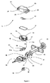
図1から8は、IOL12を保管する役割を果たすカセット11を示す。カセット11は、図1及び2に詳細に示される。カセット11は、カバー14により部分的に閉鎖されるカセット本体13と、流体密封でカセット本体13を閉鎖するカセットリッド23とから構成される。カセット11を用いて、インジェクタ31のアパーチャ39内にIOL12を注入することができる(図1及び3から8)。
1 to 8 show a
カセット本体13は、IOL12を受けるためのスペース19を有する。受入スペース19において受けるIOL12を排出するためにインジェクタピストン20が延びることができる開口17a、17bは、カセット本体の対向する側壁に設けられる。突起、抑え装置及び同様のものなどの手段は、受入スペース19に設けられ、IOL12を正確な定められた位置に固定することができる。インジェクタ31のジャーナル容器41内に嵌合的に挿入できるジャーナル15は、カセット本体13の下面にモールド成形又は配設される(図2から4はカセット11及びインジェクタ31の詳細を示す)。ジャーナル容器41は、アパーチャ39内の支持部37の上側で中心に設けられる。ジャーナル15又はカセット本体13は、クリップ43によりジャーナル容器41内に回転可能に固定される。クリップは、装着された状態でジャーナル15の円筒容器47を通って延びる2つの可撓性フック45を有し、この容器は中心ラインとして回転軸18を有する。可撓性フック45は、この事例では、容器47に対して横方向に向けられた2つのアパーチャ49にロックされる。カセットがインジェクタに挿入されると、クリップ43は、カセットが再度取り外し可能になるのが阻止される。
The
カセットがインジェクタ31に挿入されると、ジャーナル15を通って延びる回転軸18の周りのカセット本体の回転が可能になる。この事例では、カセット本体は、整列された開口17a、17が注入方向に対して横断して位置付けられる保管位置から、開口17a、17が注入方向と整列される注入位置に枢動できるようにされる。ジャーナル15は、断面が正八角形として設計される。ジャーナル容器41に挿入されるバネ要素22は、カセット本体が注入位置に枢動するようにされると、カセット本体13を固定する役割を果たす。バネ要素22は、2つの延長部51a、510bによってジャーナル容器41内に支持され、インジェクタ31に対する望ましくない回転を阻止するようにする。バネ要素22は、延長部51a、51bに加えて、延長部51a、51bがモールド成形される正八角形滅菌リングから構成される。八角形リング53は、八角形ジャーナル15を嵌合的に囲む。バネ要素22をインジェクタ31上にモールド成形することも考えられる。
When the cassette is inserted into the
カセット本体13が保管位置から注入位置に回転されると、注入位置においてジャーナルの側部がリング53の側部上に再度載るようになり、ジャーナル15がリング53をロックするまで、リング53はジャーナル15を弾性的に放出する。ジャーナル容器における八角形リングの回転を可能にするように、八角形リングがジャーナル容器から離れて設定されることが重要である。
When the
カセット本体13が注入位置に正確に向けられるのを確保するには、方向矢印をカバー14の上に可視にすることができる。また、ジャーナル15をカセット本体13の下面に偏心してモールド成形することも考えられる。誤った方向で回転している間、カセット本体14は、注入位置になる前にインジェクタ31に当接する。
A directional arrow can be visible on the
カセット11の閉鎖状態でカセットリッド23がその上に載りシールを生成する周辺リングシール21は、カセット本体13の外部に設けられる。リングシール21は、周辺溝32で受けられる。また、カセット本体13上ではなく、カセットリッド上に溝を設けることも考えられる。2つの延長部24は、短側部にてカセットリッド23上にモールド成形される。枢動レバー25は、延長部の各々に中心に及び回転可能に配設される。カセットリッド23によるカセット本体13の閉鎖中、枢動レバーが90°回転される。成型相互連結延長部26は、カセット本体13の長側部の底面において形成された相互連結アパーチャ27と係合する。リッドの縁部はリングシール21を圧迫する。これにより保管液体の望ましくない放出が確実に防止される。カセット11は、120℃を上回る従来の滅菌温度に耐える生体適合性プラスチック材料から作られる。
A
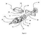
図5から8は、支持体37上に成型される注入ノズル33及びインジェクタ本体35を備えたインジェクタ31を示している。インジェクタピストン20は、注入ノズル33から遠隔の端面から注入本体35に延びる。注入ノズル33及びインジェクタ本体35は、注入ノズル33及びインジェクタ本体35間でカセット11を受ける役割を果たすアパーチャ39を形成するようにして支持体37上に配設される。アパーチャ39の長さは、開口17a及び17b間の距離に正確に対応する。その結果、カセット本体13の注入位置において、カセット本体13と注入ノズル33との間又はカセット本体13とインジェクタ本体35との間の移行はギャップ無しである。
5 to 8 show an
本発明による注入システムは、以下のように機能する。すなわち、製造中、カセット本体13は、相互に整列した開口17a、17bが注入方向に対して横方向に配設され、次いで滅菌(例えば、ETO、ガンマ線、又はオートクレーブ処理)されるようにして、インジェクタ31上に固定されたカセットリッド23により気密シールされるIOL12及び保管液体を備える。カセット11が横方向に設置されることの結果として、カセットリッド23と共にカセット11をインジェクタ31上に固定するためのスペースが存在する。続いて、予装填された注入システムは、シースルーパッケージ内に滅菌形態にパックされて顧客に出荷することができる。インジェクタシステムの送出状態は図4から分かる。眼球内レンズが液体中で受けられるので、受入スペースは外部環境から気密閉鎖され、レンズは、数ヶ月及び数年でも問題なく保管することができる。しかしながら、インプラントの直前にカセットだけを滅菌してインジェクタに取り付けることも考えられる。
The injection system according to the present invention functions as follows. That is, during manufacture, the
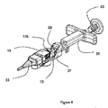
IOLの間近の注入において、ユーザは、パッケージから予装填インジェクタシステムを取り出し、2つの枢動レバー25を開いて、カセットカバー23を取り除く。保管液体は、適切な場合取り除かれる(図5)。その後、IOL受入スペース19及びインジェクタノズルが潤滑剤で充填され、カセット本体13は、ガイドジャーナル15が窪み45内にロックされるまで90°回転される。この位置において、カセットは正確な向きにされ、インジェクタピストンが開口17aを通って受入スペース19内に貫通し、IOLを開口17bに通してインジェクタノズルに、更に該インジェクタノズルから排出する。
In an infusion near the IOL, the user removes the preload injector system from the package, opens the two
11 カセット
12 IOL
13 カセット本体
14 カバー
15 ジャーナル
16 誘導ジャーナル
17a,17b 開口
18 回転軸
19 受入スペース
20 インジェクタピストン
21 リングシール
22 バネ要素
23 カセットリッド
24 延長部
25 枢動レバー
26 相互連結延長部
27 相互連結アパーチャ
31 インジェクタ
32 周辺溝
33 注入ノズル
35 インジェクタ本体
37 支持体
39 アパーチャ
41 ジャーナル容器
43 クリップ
47 円筒形容器
49 アパーチャ
51 延長部
53 八角形リング
11
13
Claims (17)
前記カセット本体(13)を閉鎖するためのカセットリッド(23)と、
前記カセット本体(13)上に設けられ、前記カセットリッド(23)により閉鎖された前記カセット本体(13)をインジェクタ(31)に締結し、且つ前記インジェクタに対して向きを定めることができる結合手段と、
とから構成され、
カセットが閉鎖されたときに、前記カセットリッド(23)が前記受入スペース(19)及び前記開口(17a、17b)を閉鎖することを特徴とするカセット。 A cassette body (13) having a space (19) for receiving the IOL (12) and having openings (17a, 17b) on opposing side walls;
A cassette lid (23) for closing the cassette body (13);
A coupling means provided on the cassette body (13) and capable of fastening the cassette body (13) closed by the cassette lid (23) to the injector (31) and determining the direction with respect to the injector. When,
And consists of
A cassette characterized in that the cassette lid (23) closes the receiving space (19) and the openings (17a, 17b) when the cassette is closed.
ことを特徴とする請求項1に記載のカセット。 A seal is provided between an edge of the cassette lid (23) and the cassette body (13);
The cassette according to claim 1.
ことを特徴とする請求項2に記載のカセット。 The seal is configured in a peripheral groove on the outer periphery of the housing of the cassette body (13).
The cassette according to claim 2 .
前記第1の結合手段は、前記インジェクタ(31)上の第2の結合手段と回転可能に相互作用することができることを特徴とする請求項1乃至3のいずれか1項に記載のカセット。 The coupling means comprises a first coupling means and a second coupling means,
4. A cassette according to any one of the preceding claims, wherein the first coupling means is capable of rotatingly interacting with second coupling means on the injector (31).
請求項1乃至9のいずれかに記載のカセット(11)は、前記アパーチャ(39)内に配置されていることを特徴とする、眼球内レンズ(33)を排出するためのインジェクタシステム。 An injector body (35) through which an injector piston (20) is guided so as to be axially displaceable, an injector front part adjacent to the piston body and having an aperture (39) for receiving a cassette (11); An injector nozzle (33) adjacent to the aperture (39) and having a proximal opening and a distal opening;
10. An injector system for discharging an intraocular lens (33), characterized in that the cassette (11) according to any of claims 1 to 9 is arranged in the aperture (39).
ことを特徴とする請求項13に記載のインジェクタシステム。 Means are provided for determining the direction of rotation of the cassette body (13).
The injector system according to claim 13.
Applications Claiming Priority (3)
| Application Number | Priority Date | Filing Date | Title |
|---|---|---|---|
| CH1492/08 | 2008-09-22 | ||
| CH01492/08A CH699588A1 (en) | 2008-09-22 | 2008-09-22 | Cartridge for an intraocular lens injector system and for it. |
| PCT/CH2009/000305 WO2010031196A1 (en) | 2008-09-22 | 2009-09-18 | Cassette for intraocular lens and preloaded lens injection system |
Publications (3)
| Publication Number | Publication Date |
|---|---|
| JP2012502700A JP2012502700A (en) | 2012-02-02 |
| JP2012502700A5 JP2012502700A5 (en) | 2012-07-26 |
| JP5571668B2 true JP5571668B2 (en) | 2014-08-13 |
Family
ID=40568653
Family Applications (1)
| Application Number | Title | Priority Date | Filing Date |
|---|---|---|---|
| JP2011527172A Active JP5571668B2 (en) | 2008-09-22 | 2009-09-18 | Intraocular lens and pre-loaded cassette for lens injection system |
Country Status (6)
| Country | Link |
|---|---|
| US (1) | US8551165B2 (en) |
| EP (1) | EP2328514B8 (en) |
| JP (1) | JP5571668B2 (en) |
| CH (1) | CH699588A1 (en) |
| ES (1) | ES2606565T3 (en) |
| WO (1) | WO2010031196A1 (en) |
Families Citing this family (21)
| Publication number | Priority date | Publication date | Assignee | Title |
|---|---|---|---|---|
| NL2005182C2 (en) * | 2010-07-30 | 2012-01-31 | Oculentis B V | Intraocular lens injector system. |
| DE102011101940B4 (en) * | 2011-05-18 | 2014-01-02 | Iolution Gmbh | Injector for implanting an intraocular lens |
| GB2493017B (en) | 2011-07-19 | 2016-08-03 | Carl Zeiss Meditec Sas | Cassette for an intraocular lens and injector device for an intraocular lens |
| WO2013038688A1 (en) * | 2011-09-15 | 2013-03-21 | 株式会社メニコン | Intraocular lens insertion tool |
| JP6015226B2 (en) * | 2011-09-30 | 2016-10-26 | 株式会社ニデック | Intraocular lens insertion device |
| AU2013271703B2 (en) | 2012-06-04 | 2017-05-11 | Alcon Inc. | Intraocular lens inserter |
| EP3766455A1 (en) | 2012-06-12 | 2021-01-20 | Alcon Inc. | Intraocular gas injector |
| WO2014074382A2 (en) * | 2012-11-07 | 2014-05-15 | Hanita Lenses R.C.A. Ltd. | Preloaded iol injector |
| DE102012223885B4 (en) * | 2012-12-20 | 2022-01-05 | Humanoptics Ag | Intraocular lens storage system, transfer arrangement and method for transferring an intraocular lens to an injection device |
| US9795474B2 (en) | 2013-10-24 | 2017-10-24 | Carl Zeiss Meditec Ag | Hydrophilic IOL packaging system |
| US20150114855A1 (en) * | 2013-10-24 | 2015-04-30 | Aaren Scientific Inc. | Hydrophilic iol packaging system |
| KR20160122164A (en) | 2014-02-20 | 2016-10-21 | 산텐 세이야꾸 가부시키가이샤 | Injector for intraocular lens |
| US10010408B2 (en) | 2014-04-04 | 2018-07-03 | Alcon Pharmaceuticals, Ltd. | Intraocular lens inserter |
| US10588780B2 (en) | 2015-03-04 | 2020-03-17 | Alcon Inc. | Intraocular lens injector |
| US10172706B2 (en) | 2015-10-31 | 2019-01-08 | Novartis Ag | Intraocular lens inserter |
| BE1024131B1 (en) * | 2016-04-21 | 2017-11-20 | Physiol S.A. | Soft intraocular lens injection device and storage shuttle for its implementation |
| US10568735B2 (en) | 2017-01-13 | 2020-02-25 | Alcon Inc. | Intraocular lens injector |
| US11000367B2 (en) | 2017-01-13 | 2021-05-11 | Alcon Inc. | Intraocular lens injector |
| US11083568B2 (en) | 2017-02-07 | 2021-08-10 | Rxsight, Inc. | Intraocular lens inserter cartridge with an IOL-guiding structure |
| US11224537B2 (en) | 2018-10-19 | 2022-01-18 | Alcon Inc. | Intraocular gas injector |
| WO2020121142A1 (en) * | 2018-12-11 | 2020-06-18 | Alcon Inc. | Haptic optic management system utilizing a squid clip |
Family Cites Families (12)
| Publication number | Priority date | Publication date | Assignee | Title |
|---|---|---|---|---|
| US4681102A (en) * | 1985-09-11 | 1987-07-21 | Bartell Michael T | Apparatus and method for insertion of an intra-ocular lens |
| DE69331807T2 (en) * | 1992-09-30 | 2002-09-26 | Vladimir Feingold | INTRAOCULAR LENS INSERTION SYSTEM |
| US5947975A (en) * | 1997-03-07 | 1999-09-07 | Canon Staar Co., Inc. | Inserting device for deformable intraocular lens |
| JP3728155B2 (en) * | 1999-10-05 | 2005-12-21 | キヤノンスター株式会社 | Intraocular lens insertion system |
| WO2003044946A2 (en) * | 2001-10-12 | 2003-05-30 | Humanoptics Ag | Device for folding an intraocular lens and system for storing an intraocular lens |
| FR2833154B1 (en) * | 2001-12-12 | 2004-11-19 | Ioltechnologie Production | CASSETTE AND FLEXIBLE INTRAOCULAR LENS INJECTOR AND METHOD FOR INJECTING SUCH LENSES |
| US7429263B2 (en) * | 2003-08-28 | 2008-09-30 | Bausch & Lomb Incorporated | Preloaded IOL injector |
| US7422604B2 (en) * | 2003-08-28 | 2008-09-09 | Bausch & Lomb Incorporated | Preloaded IOL injector |
| US20070060925A1 (en) * | 2003-09-26 | 2007-03-15 | Joel Pynson | Preloaded iol injector and method |
| US7740636B2 (en) * | 2005-04-15 | 2010-06-22 | Abbott Medical Optics Inc. | Multi-action device for inserting an intraocular lens into an eye |
| US7879090B2 (en) * | 2006-12-13 | 2011-02-01 | Bausch & Lomb Incorporated | Intraocular lens injector apparatus and methods of use |
| CH700436B1 (en) * | 2007-02-15 | 2010-08-31 | Medicel Ag Technology For Surg | Apparatus and injector for folding an intraocular lens. |
-
2008
- 2008-09-22 CH CH01492/08A patent/CH699588A1/en not_active Application Discontinuation
-
2009
- 2009-09-18 JP JP2011527172A patent/JP5571668B2/en active Active
- 2009-09-18 US US13/120,373 patent/US8551165B2/en active Active
- 2009-09-18 WO PCT/CH2009/000305 patent/WO2010031196A1/en active Application Filing
- 2009-09-18 ES ES09775788.4T patent/ES2606565T3/en active Active
- 2009-09-18 EP EP09775788.4A patent/EP2328514B8/en active Active
Also Published As
| Publication number | Publication date |
|---|---|
| CH699588A1 (en) | 2010-03-31 |
| US20110190777A1 (en) | 2011-08-04 |
| US8551165B2 (en) | 2013-10-08 |
| ES2606565T3 (en) | 2017-03-24 |
| WO2010031196A8 (en) | 2011-03-10 |
| EP2328514B8 (en) | 2016-12-21 |
| EP2328514A1 (en) | 2011-06-08 |
| EP2328514B1 (en) | 2016-11-09 |
| WO2010031196A1 (en) | 2010-03-25 |
| JP2012502700A (en) | 2012-02-02 |
Similar Documents
| Publication | Publication Date | Title |
|---|---|---|
| JP5571668B2 (en) | Intraocular lens and pre-loaded cassette for lens injection system | |
| CA2565395C (en) | Conditioning device for injecting the intraocular lens | |
| US8562674B2 (en) | Front loading IOL insertion apparatus and method of using | |
| CN101094624B (en) | Preloaded iol injector and method | |
| AU2005322351B2 (en) | Preloaded IOL injector and method | |
| ES2365514T3 (en) | PREPARATION METHOD OF A PRECARGED IOL INJECTOR. | |
| JP5391332B2 (en) | Intraocular lens cartridge | |
| BRPI1008638B1 (en) | INTRAOCULAR LENS INJECTOR CARTRIDGE ASSEMBLY | |
| FR2833154A1 (en) | CASSETTE AND FLEXIBLE INTRAOCULAR LENS INJECTOR AND METHOD FOR INJECTING SUCH LENSES | |
| US20150045805A1 (en) | Device for injecting an intraocular lens into an eye | |
| KR20150032251A (en) | Pre-loaded injector for use with intraocular lens | |
| CN111712215B (en) | Injector system for intraocular lenses | |
| US20210068944A1 (en) | Flexible intraocular lens injection device and storage shuttle for implementing same | |
| JP6758369B2 (en) | Auxiliary for storage and injection of intraocular lenses | |
| WO2014207538A2 (en) | Pre-loaded intraocular lens delivery device |
Legal Events
| Date | Code | Title | Description |
|---|---|---|---|
| A521 | Request for written amendment filed |
Free format text: JAPANESE INTERMEDIATE CODE: A523 Effective date: 20120608 |
|
| A621 | Written request for application examination |
Free format text: JAPANESE INTERMEDIATE CODE: A621 Effective date: 20120608 |
|
| A977 | Report on retrieval |
Free format text: JAPANESE INTERMEDIATE CODE: A971007 Effective date: 20130724 |
|
| A131 | Notification of reasons for refusal |
Free format text: JAPANESE INTERMEDIATE CODE: A131 Effective date: 20130806 |
|
| A521 | Request for written amendment filed |
Free format text: JAPANESE INTERMEDIATE CODE: A523 Effective date: 20131105 |
|
| A131 | Notification of reasons for refusal |
Free format text: JAPANESE INTERMEDIATE CODE: A131 Effective date: 20140121 |
|
| A521 | Request for written amendment filed |
Free format text: JAPANESE INTERMEDIATE CODE: A523 Effective date: 20140318 |
|
| TRDD | Decision of grant or rejection written | ||
| A01 | Written decision to grant a patent or to grant a registration (utility model) |
Free format text: JAPANESE INTERMEDIATE CODE: A01 Effective date: 20140610 |
|
| A61 | First payment of annual fees (during grant procedure) |
Free format text: JAPANESE INTERMEDIATE CODE: A61 Effective date: 20140626 |
|
| R150 | Certificate of patent or registration of utility model |
Ref document number: 5571668 Country of ref document: JP Free format text: JAPANESE INTERMEDIATE CODE: R150 |
|
| R250 | Receipt of annual fees |
Free format text: JAPANESE INTERMEDIATE CODE: R250 |
|
| R250 | Receipt of annual fees |
Free format text: JAPANESE INTERMEDIATE CODE: R250 |
|
| R250 | Receipt of annual fees |
Free format text: JAPANESE INTERMEDIATE CODE: R250 |
|
| R250 | Receipt of annual fees |
Free format text: JAPANESE INTERMEDIATE CODE: R250 |
|
| R250 | Receipt of annual fees |
Free format text: JAPANESE INTERMEDIATE CODE: R250 |
|
| R250 | Receipt of annual fees |
Free format text: JAPANESE INTERMEDIATE CODE: R250 |
|
| R250 | Receipt of annual fees |
Free format text: JAPANESE INTERMEDIATE CODE: R250 |