JP5571509B2 - Electronically controlled valve drive device for internal combustion engine - Google Patents

Electronically controlled valve drive device for internal combustion engine Download PDF

Info

Publication number
JP5571509B2
JP5571509B2 JP2010192245A JP2010192245A JP5571509B2 JP 5571509 B2 JP5571509 B2 JP 5571509B2 JP 2010192245 A JP2010192245 A JP 2010192245A JP 2010192245 A JP2010192245 A JP 2010192245A JP 5571509 B2 JP5571509 B2 JP 5571509B2
Authority
JP
Japan
Prior art keywords
piston
valve
hydraulic
control
flow rate
Prior art date
Legal status (The legal status is an assumption and is not a legal conclusion. Google has not performed a legal analysis and makes no representation as to the accuracy of the status listed.)
Expired - Fee Related
Application number
JP2010192245A
Other languages
Japanese (ja)
Other versions
JP2012047151A (en
Inventor
元幸 高橋
Current Assignee (The listed assignees may be inaccurate. Google has not performed a legal analysis and makes no representation or warranty as to the accuracy of the list.)
Mitsui Engineering and Shipbuilding Co Ltd
Mitsui E&S Holdings Co Ltd
Original Assignee
Mitsui Engineering and Shipbuilding Co Ltd
Mitsui E&S Holdings Co Ltd
Priority date (The priority date is an assumption and is not a legal conclusion. Google has not performed a legal analysis and makes no representation as to the accuracy of the date listed.)
Filing date
Publication date
Application filed by Mitsui Engineering and Shipbuilding Co Ltd, Mitsui E&S Holdings Co Ltd filed Critical Mitsui Engineering and Shipbuilding Co Ltd
Priority to JP2010192245A priority Critical patent/JP5571509B2/en
Publication of JP2012047151A publication Critical patent/JP2012047151A/en
Application granted granted Critical
Publication of JP5571509B2 publication Critical patent/JP5571509B2/en
Expired - Fee Related legal-status Critical Current
Anticipated expiration legal-status Critical

Links

Images

Description

本発明は、内燃機関の電子制御式弁駆動装置に関する。   The present invention relates to an electronically controlled valve driving apparatus for an internal combustion engine.

従来、内燃機関、例えばディーゼル機関の電子制御式弁駆動装置として、図17に示すような構成の電子制御式排気弁駆動装置がある。この電子制御式排気弁駆動装置201は、排気弁202を開弁するときには、図示しない電子制御装置により駆動される電磁式のソレノイド弁203により方向制御弁204を開弁側に切り替えて、油圧ポンプ205、アキュームレータ206などからなる油圧源207から、高圧の油圧を高圧管208、方向制御弁204、高圧管209を通して、排気弁202の最大リフトを制御する油圧アクチュエータ211に供給する。   2. Description of the Related Art Conventionally, as an electronically controlled valve drive device for an internal combustion engine, for example, a diesel engine, there is an electronically controlled exhaust valve drive device configured as shown in FIG. When the exhaust valve 202 is opened, the electronically controlled exhaust valve driving device 201 switches the direction control valve 204 to the valve-opening side by an electromagnetic solenoid valve 203 driven by an electronic control device (not shown). High pressure hydraulic pressure is supplied from a hydraulic pressure source 207 including 205, an accumulator 206, and the like to the hydraulic actuator 211 that controls the maximum lift of the exhaust valve 202 through the high pressure pipe 208, the direction control valve 204, and the high pressure pipe 209.

油圧アクチュエータ211は、フルストローク位置まで図示上方に移動し、この油圧アクチュエータ211内の油圧が高圧管212を通して、排気弁202に取付けられた油圧シリンダ213に導かれる。この油圧シリンダ213には、排気弁202のオーバーシュートや衝撃的着座を回避するため、ダンパ215付きの油圧ピストン214が装備されている。   The hydraulic actuator 211 moves upward in the drawing to the full stroke position, and the hydraulic pressure in the hydraulic actuator 211 is guided to the hydraulic cylinder 213 attached to the exhaust valve 202 through the high pressure pipe 212. The hydraulic cylinder 213 is equipped with a hydraulic piston 214 with a damper 215 in order to avoid overshoot and shocking seating of the exhaust valve 202.

上述の油圧アクチュエータ211から導かれた高圧の油圧は、空気ばね216のばね力に抗して、油圧ピストン214を図中下方に一気に移動させて、排気弁202を最大リフトさせる。排気弁202は、最大リフトに近づくとダンパ215により弁速度が減速されて、オーバーシュートすることなく最大リフトとなり全開する。   The high-pressure oil pressure guided from the above-described hydraulic actuator 211 moves the hydraulic piston 214 downward in the drawing against the spring force of the air spring 216 to lift the exhaust valve 202 to the maximum. When the exhaust valve 202 approaches the maximum lift, the valve speed is reduced by the damper 215, and the exhaust valve 202 is fully opened without being overshot.

排気弁202を閉弁するときには、方向制御弁204を閉弁側に切り替えると、空気ばね216のばね力により油圧ピストン214が図中上方に移動し、油圧シリンダ213内の油圧が高圧管212を通して油圧アクチュエータ211に導かれる。油圧アクチュエータ211に導かれた油圧は、高圧管209、方向制御弁204、低圧管210を通してタンク217に排出される。排気弁202は、着座するときに、上述のダンパ215の作用により、弁速度が減速されて滑らかな着座が行われる。   When the exhaust valve 202 is closed, when the direction control valve 204 is switched to the valve closing side, the hydraulic piston 214 moves upward in the figure by the spring force of the air spring 216, and the hydraulic pressure in the hydraulic cylinder 213 passes through the high pressure pipe 212. Guided to the hydraulic actuator 211. The hydraulic pressure guided to the hydraulic actuator 211 is discharged to the tank 217 through the high pressure pipe 209, the direction control valve 204, and the low pressure pipe 210. When the exhaust valve 202 is seated, the valve speed is reduced by the action of the above-described damper 215 and smooth seating is performed.

また、内燃機関の弁駆動装置として、例えば特開平2−248607号公報に開示されているものがある(例えば、特許文献1参照)。この弁駆動装置は、内燃機関の吸排気弁を開弁方向に付勢する付勢手段と、吸排気弁を作動油圧により付勢手段の付勢力に抗して開弁させる油圧手段とを備え、油圧手段に対して作動油を給排して吸排気弁を開閉させるようにした内燃機関の弁駆動装置であり、油圧手段に作動油を供給する供給系又は油圧手段の作動油を排出する排出系の少なくとも一方に配設されたロジック弁等の開閉弁と、開閉弁の開閉時間を切り換える電磁切換弁とを備えている。   Further, as a valve driving device for an internal combustion engine, for example, there is one disclosed in Japanese Patent Laid-Open No. 2-248607 (for example, see Patent Document 1). This valve drive device includes an urging means for urging the intake / exhaust valve of the internal combustion engine in the valve opening direction, and a hydraulic means for opening the intake / exhaust valve against the urging force of the urging means by operating hydraulic pressure. , A valve drive device for an internal combustion engine that supplies and discharges hydraulic oil to and from the hydraulic means to open and close the intake and exhaust valves, and discharges hydraulic oil from a supply system or hydraulic means that supplies hydraulic oil to the hydraulic means An opening / closing valve such as a logic valve disposed in at least one of the discharge systems and an electromagnetic switching valve for switching an opening / closing time of the opening / closing valve are provided.

しかしながら、上述の従来の電子制御式排気弁駆動装置201は、油圧アクチュエータ211、高圧管212のほか、排気弁駆動装置の内部に設けられたダンパ215が必要になるなど、部品点数が多くなり、コスト高になるという問題がある。また、方向制御弁204と油圧シリンダ213との間に組み込まれた油圧アクチュエータ211や、排気弁202に組み込まれたダンパ215付き油圧ピストン214は極めて大型であり、機構全体が大型になりスペースが確保できず点検等における作業性が悪い。   However, the above-described conventional electronically controlled exhaust valve driving device 201 requires a number of parts such as a hydraulic actuator 211, a high-pressure pipe 212, and a damper 215 provided inside the exhaust valve driving device. There is a problem of high costs. Further, the hydraulic actuator 211 incorporated between the directional control valve 204 and the hydraulic cylinder 213 and the hydraulic piston 214 with the damper 215 incorporated in the exhaust valve 202 are extremely large, and the entire mechanism is large and space is secured. Workability in inspection etc. is poor.

また、ダンパ215には、耐熱性の観点から特殊合金が使用されているために、機械加工が難しく、高価になるという問題もある。特許文献1に記載された弁駆動装置についても、同様の問題が考えられる。   Further, since a special alloy is used for the damper 215 from the viewpoint of heat resistance, there is a problem that machining is difficult and expensive. The same problem can be considered for the valve drive device described in Patent Document 1.

そこで、本願発明者は、特願2009─055202により、図18に示すように、内燃機関の弁駆動装置に収容された弁221に取付けられて、当該弁221を開弁させる油圧ピストン222と、油圧ピストン222に油圧を供給する油圧発生手段233と、油圧発生手段233からの油圧を油圧ピストン222に供給し又は油圧ピストン222から排出する方向制御弁231と、方向制御弁231と油圧ピストン222との間に接続されるダンピング・アクチュエータ225とを備える内燃機関の電子制御式弁駆動装置を提案した。   Therefore, as shown in FIG. 18, the inventor of the present application, as shown in FIG. 18, attaches to a valve 221 accommodated in a valve drive device of an internal combustion engine and opens the valve 221. A hydraulic pressure generating means 233 for supplying hydraulic pressure to the hydraulic piston 222; a directional control valve 231 for supplying or discharging the hydraulic pressure from the hydraulic pressure generating means 233 to the hydraulic piston 222; a directional control valve 231 and a hydraulic piston 222; Proposed an electronically controlled valve drive for an internal combustion engine comprising a damping actuator 225 connected between the two.

そして、この内燃機関の電子制御式弁駆動装置については、特に油圧アクチュエータを、方向制御弁231から供給される油圧により油圧ピストン222を駆動するアクチュエータ機能と、油圧ピストン222の駆動速度を抑制するダンピング機能とを併せ持つダンピング・アクチュエータ225からなるものとした。   In this electronically controlled valve drive device for an internal combustion engine, in particular, a hydraulic actuator is provided with an actuator function for driving the hydraulic piston 222 by the hydraulic pressure supplied from the direction control valve 231, and damping for suppressing the driving speed of the hydraulic piston 222. The damping actuator 225 has both functions.

このダンピング・アクチュエータ225は、方向制御弁231に連通するポートに接続されて方向制御弁231から当該ダンピング・アクチュエータ225のアクチュエータピストン227への油圧の移動を許容する第1の逆止弁240と、第1の逆止弁240と並列に接続されてアクチュエータピストン227の作動終了時の速度を抑えるべくアクチュエータピストン227の動きに応じて閉塞される複数の油路からなる第1のバイパス油路242とを備えている。   The damping actuator 225 is connected to a port communicating with the direction control valve 231, and a first check valve 240 that allows the hydraulic pressure to move from the direction control valve 231 to the actuator piston 227 of the damping actuator 225, A first bypass oil passage 242 which is connected in parallel with the first check valve 240 and is composed of a plurality of oil passages which are closed in accordance with the movement of the actuator piston 227 to suppress the speed at the end of the operation of the actuator piston 227; It has.

また、このダンピング・アクチュエータ225は、弁221に取付けられた油圧ピストン222に連通するポートに接続されて油圧ピストン222から当該ダンピング・アクチュエータ225のアクチュエータピストン227への油圧の移動を許容する第2の逆止弁241と、この第2の逆止弁241と並列に接続されてアクチュエータピストン227の作動終了時の速度を抑えるべくアクチュエータピストン227の動きに応じて閉塞される複数の油路からなる第2のバイパス油路243とを備えている。   Further, the damping actuator 225 is connected to a port communicating with the hydraulic piston 222 attached to the valve 221 to allow a second hydraulic pressure to move from the hydraulic piston 222 to the actuator piston 227 of the damping actuator 225. A check valve 241 and a second oil passage that is connected in parallel with the second check valve 241 and is closed according to the movement of the actuator piston 227 to suppress the speed at the end of the operation of the actuator piston 227. 2 bypass oil passages 243.

特開平2−248607号公報(4−7頁、図1)JP-A-2-248607 (page 4-7, FIG. 1)

本願発明者が上記特願2009─055202により提案した内燃機関の電子制御式弁駆動装置は、油圧アクチュエータを、油圧ピストン222を駆動するアクチュエータ機能と、油圧ピストン222の駆動速度を抑制するダンピング機能とを併せ持つダンピング・アクチュエータ225からなるものとしたことにより、従来は排気弁駆動装置の内部に設けられたダンパを排除するなど、部品点数を大幅に減少させ、製造コストを大幅に削減させるものとなり、また、機構全体を小型化することができ、スペース等が確保されて、点検等における作業性が極めてよいものとなり、さらに、高圧配管系のキャビテーション・エロージョンの発生を抑えることができるものとなった。   The electronic control type valve drive device for an internal combustion engine proposed by the present inventor in the above Japanese Patent Application No. 2009-055202 includes a hydraulic actuator, an actuator function for driving the hydraulic piston 222, and a damping function for suppressing the driving speed of the hydraulic piston 222. By using the damping actuator 225 that has both, the number of parts has been greatly reduced, such as eliminating the damper provided inside the exhaust valve drive device, and the manufacturing cost has been greatly reduced. In addition, the entire mechanism can be reduced in size, space is secured, workability in inspection, etc. is extremely good, and the occurrence of cavitation and erosion in the high-pressure piping system can be suppressed. .

しかしながら、このダンピング・アクチュエータ225は、上述のように、ダンピング機能を2つの逆止弁240,241と、複数の油路からなる2つのバイパス油路242,243とからなる構成のため、ダンピング・アクチュエータの構造が複雑かつ大型化し、製造コストが高くなる可能性が考えられる。   However, as described above, the damping actuator 225 has a damping function because it is configured by the two check valves 240 and 241 and the two bypass oil passages 242 and 243 including a plurality of oil passages. There is a possibility that the structure of the actuator is complicated and large, and the manufacturing cost is high.

本発明は、このような問題を解決するためになされたもので、開弁時には最大リフト位置に滑らかに近づけてオーバーシュートを確実に防止し、閉弁時には滑らかに着座させてジャンピングを確実に防止することができると共に、特に構成が簡単で小型化することができ、製造コストを大幅に削減することができる、内燃機関の電子制御式弁駆動装置を提供することを課題とする。   The present invention has been made to solve such problems. When the valve is opened, the maximum lift position is smoothly brought close to prevent overshoot, and when the valve is closed, the seat is smoothly seated to prevent jumping. It is another object of the present invention to provide an electronically controlled valve drive device for an internal combustion engine that can be reduced in size, can be reduced in size, and can greatly reduce manufacturing costs.

上記の課題を解決するために、本発明が採用する手段は、内燃機関の弁駆動装置に収容された弁に取付けられて当該弁を開弁させる油圧ピストンと、油圧ピストンに油圧を供給する油圧発生手段と、油圧発生手段からの油圧を油圧ピストンに供給し又は油圧ピストンの油圧を排出する方向制御弁と、方向制御弁と油圧ピストンとの間に接続されて方向制御弁により供給又は排出される油圧により油圧ピストンを駆動する油圧アクチュエータと、油圧アクチュエータの内部に設けられて弁のリフト時に油圧ピストンに供給する油圧の流量を制御すると共に、弁の着座時に油圧ピストンから排出させる油圧の流量を制御して油圧ピストンの駆動速度を抑制する流量制御ピストンとを備えたことにある。   In order to solve the above-described problems, the means employed by the present invention includes a hydraulic piston that is attached to a valve housed in a valve drive device of an internal combustion engine and opens the valve, and a hydraulic pressure that supplies hydraulic pressure to the hydraulic piston. Generating means, a directional control valve for supplying the hydraulic pressure from the hydraulic pressure generating means to the hydraulic piston or discharging the hydraulic pressure of the hydraulic piston, and being connected between the directional control valve and the hydraulic piston and supplied or discharged by the directional control valve. The hydraulic actuator that drives the hydraulic piston by the hydraulic pressure and the flow rate of the hydraulic pressure that is provided inside the hydraulic actuator and that is supplied to the hydraulic piston when the valve is lifted, and that is discharged from the hydraulic piston when the valve is seated And a flow rate control piston that controls and suppresses the drive speed of the hydraulic piston.

本発明の内燃機関の電子制御式弁駆動装置において、油圧アクチュエータの内部に設けた流量制御ピストンにより弁のリフト時に油圧ピストンに供給する油圧の流量を制御し、また、弁の着座時に油圧ピストンから排出させる油圧の流量を制御して油圧ピストンの駆動速度を抑制することにより、開弁時には最大リフト位置に滑らかに近づけ、閉弁時には滑らかに着座させることが可能となる。これにより、開弁時における弁のオーバーシュート及び閉弁時における弁のジャンピングを確実に防止することができる。   In the electronically controlled valve driving apparatus for an internal combustion engine of the present invention, the flow rate of the hydraulic pressure supplied to the hydraulic piston is controlled when the valve is lifted by the flow control piston provided in the hydraulic actuator, and the hydraulic piston is controlled when the valve is seated. By controlling the flow rate of the hydraulic pressure to be discharged and suppressing the driving speed of the hydraulic piston, it is possible to smoothly approach the maximum lift position when the valve is opened and to be seated smoothly when the valve is closed. Thereby, the overshoot of the valve at the time of valve opening and the jumping of the valve at the time of valve closing can be reliably prevented.

特に、油圧アクチュエータの内部に流量制御ピストンを設けたことにより、流量制御機構が、例えば2つの逆止弁と複数の油路からなる2つのバイパス油路とからなるものに比べて、構造が簡単で小型化することができ、製造コストを大幅に削減することができる。   In particular, by providing a flow control piston inside the hydraulic actuator, the flow control mechanism is simpler in structure than, for example, a structure including two check valves and two bypass oil passages composed of a plurality of oil passages. Therefore, the manufacturing cost can be greatly reduced.

上記内燃機関の電子制御式弁駆動装置において、流量制御ピストンは、油圧アクチュエータのピストンの油圧ピストン側の端面に設けられた弁リフト制御ピストンと、油圧アクチュエータのピストンの方向制御弁側の端面に設けられた弁着座制御ピストンとからなることが望ましい。   In the electronically controlled valve drive apparatus for an internal combustion engine, the flow control piston is provided on a valve lift control piston provided on an end surface of the hydraulic actuator piston on the hydraulic piston side, and on an end surface of the hydraulic actuator piston on the direction control valve side. And a valve seating control piston.

このように、流量制御ピストンを油圧アクチュエータのピストンの端面に設けた弁リフト制御ピストンと弁着座制御ピストンとにより構成することにより、より簡単な構成とすることができると共に、製造コストの大幅な削減を図ることができる。   As described above, the flow control piston is configured by the valve lift control piston and the valve seating control piston provided on the end face of the piston of the hydraulic actuator, so that the structure can be simplified and the manufacturing cost can be greatly reduced. Can be achieved.

上記内燃機関の電子制御式弁駆動装置において、弁リフト制御ピストンは、油圧ピストンに連通する油路に液密に嵌合可能とされると共に先端部が滑らかに縮径されて流量制御部とされ、弁着座制御ピストンは、方向制御弁に連通する油路に液密に嵌合可能とされると共に先端部が滑らかに縮径されて流量制御部とされていることが望ましい。   In the electronically controlled valve drive system for an internal combustion engine, the valve lift control piston can be fitted in a fluid-tight manner in an oil passage communicating with the hydraulic piston, and the tip is smoothly reduced in diameter to serve as a flow control unit. It is desirable that the valve seating control piston can be fluid-tightly fitted into an oil passage communicating with the direction control valve, and the tip portion is smoothly reduced in diameter to serve as a flow rate control unit.

このように、弁リフト制御ピストンと弁着座制御ピストンの滑らかなテーパをなして縮径する流量制御部は、弁リフト制御ピストン及び弁着座制御ピストンとこれらのピストンに液密に嵌合する油路との隙間面積を、徐々にかつスムーズに変化させることができる。これにより、弁リフト制御ピストンは、弁が最大リフトに近づくと弁速度を確実に減速させてオーバーシュートを防止し、弁着座制御ピストンは、弁が着座する時に弁速度を減速させ滑らかに着座させて、ジャンピングを確実に防止することができる。   As described above, the flow rate control unit that reduces the diameter of the valve lift control piston and the valve seating control piston with a smooth taper includes the valve lift control piston and the valve seating control piston, and an oil passage that is liquid-tightly fitted to these pistons. Can be gradually and smoothly changed. As a result, the valve lift control piston reliably decelerates the valve speed to prevent overshoot when the valve approaches the maximum lift, and the valve seating control piston decelerates the valve speed when the valve is seated and makes it sit smoothly. Thus, jumping can be reliably prevented.

上記内燃機関の電子制御式弁駆動装置において、弁リフト制御ピストンと弁着座制御ピストンは、これらのピストンと嵌合する油路との隙間面積を油圧アクチュエータのピストンの軸方向位置に応じて流量制御部により油圧の流量を制御することが望ましい。   In the electronically controlled valve drive device for an internal combustion engine, the valve lift control piston and the valve seating control piston control the flow rate of the clearance area between the oil passages fitted to these pistons according to the axial position of the piston of the hydraulic actuator. It is desirable to control the hydraulic flow rate by the unit.

このように、油圧アクチュエータのピストンの軸方向位置に応じて弁リフト制御ピストンと弁着座制御ピストンが嵌合する油路との隙間面積を制御することにより、弁を駆動する油圧ピストンに供給する油圧の流量と油圧ピストンから排出させる油圧の流量を制御して弁の速度を減速することができ、弁が最大リフトに近づく時、又は弁が着座する時に弁速度をスムーズに減速させることができる。   In this way, the hydraulic pressure supplied to the hydraulic piston that drives the valve by controlling the clearance area between the valve lift control piston and the oil passage in which the valve seating control piston fits in accordance with the axial position of the piston of the hydraulic actuator. And the hydraulic flow rate discharged from the hydraulic piston can be controlled to reduce the valve speed, and the valve speed can be smoothly reduced when the valve approaches the maximum lift or when the valve is seated.

上記内燃機関の電子制御式弁駆動装置において、弁リフト制御ピストン及び弁着座制御ピストンは、油圧アクチュエータのピストンの端面に設けられたピストン収容孔に入出可能に収容されると共にこれらのピストン収容孔の底端部とピストンの基端部との間に縮設されたスプリングによりピストンの端面から突出していることが望ましい。   In the electronically controlled valve drive device for an internal combustion engine, the valve lift control piston and the valve seating control piston are accommodated in a piston accommodation hole provided in an end face of the piston of the hydraulic actuator so as to be able to enter and exit, and the piston accommodation holes It is desirable that the spring protrudes from the end surface of the piston by a spring contracted between the bottom end portion and the base end portion of the piston.

このように、弁リフト制御ピストンと弁着座制御ピストンを油圧アクチュエータのピストンの端面に設けたピストン収容孔に入出可能に収容して、スプリングによりピストンの端面から突出させることにより、弁リフト制御ピストン又は弁着座制御ピストンが油路に嵌合している状態でその先端部に油圧がかかったとき、油路に嵌合している弁リフト制御ピストン又は弁着座制御ピストンが、スプリング力に抗してピストン収容孔に徐々に入り込む。その結果、弁リフト制御ピストン又は弁着座制御ピストンと油路との隙間面積が徐々に広げられて、油圧アクチュエータのピストンの端面にかかる油圧が徐々に高められていく。   In this way, the valve lift control piston and the valve seating control piston are accommodated in a piston accommodation hole provided in the end face of the piston of the hydraulic actuator, and protruded from the end face of the piston by the spring, thereby allowing the valve lift control piston or When hydraulic pressure is applied to the tip of the valve seating control piston fitted in the oil passage, the valve lift control piston or valve seating control piston fitted in the oil passage will resist the spring force. Gradually enter the piston housing hole. As a result, the clearance area between the valve lift control piston or the valve seating control piston and the oil passage is gradually widened, and the hydraulic pressure applied to the end face of the piston of the hydraulic actuator is gradually increased.

上記内燃機関の電子制御式弁駆動装置において、弁リフト制御ピストンには、一端が流量制御部の先端部に開口すると共に他端が油圧アクチュエータのピストンのピストン収容孔に開口するピストン油路が設けられ、油圧アクチュエータのピストンには、一端が当該ピストンの弁リフト制御ピストン側の端面に開口すると共に他端がピストン収容孔に開口して弁リフト制御ピストンの軸方向位置に応じて弁リフト制御ピストンのピストン油路に連通することができるピストン油路が設けられていることが望ましい。   In the electronically controlled valve drive system for an internal combustion engine, the valve lift control piston is provided with a piston oil passage having one end opened at the tip of the flow rate controller and the other end opened in the piston accommodation hole of the piston of the hydraulic actuator. One end of the piston of the hydraulic actuator opens to the end face of the piston on the valve lift control piston side, and the other end opens to the piston housing hole, and the valve lift control piston according to the axial position of the valve lift control piston It is desirable that a piston oil passage that can communicate with the piston oil passage is provided.

また、上記内燃機関の電子制御式弁駆動装置において、弁着座制御ピストンには、一端が流量制御部の先端部に開口すると共に他端が油圧アクチュエータのピストンのピストン収容孔に開口するピストン油路が設けられ、油圧アクチュエータのピストンには、一端が当該ピストンの弁着座制御ピストン側の端面に開口すると共に他端がピストン収容孔に開口して弁着座制御ピストンの軸方向位置に応じて弁着座制御ピストンのピストン油路に連通することができるピストン油路が設けられていることが望ましい。   Further, in the electronically controlled valve driving apparatus for an internal combustion engine, the valve seat control piston has a piston oil passage having one end opened at a tip end portion of the flow rate control unit and the other end opened at a piston accommodation hole of a piston of a hydraulic actuator. The piston of the hydraulic actuator has one end opened to the end face of the piston on the valve seating control piston side and the other end opened to the piston receiving hole, and the valve seating is controlled according to the axial position of the valve seating control piston. It is desirable that a piston oil passage that can communicate with the piston oil passage of the control piston is provided.

このように、弁リフト制御ピストン又は弁着座制御ピストンに、一端が流量制御部の先端部に開口すると共に他端が油圧アクチュエータのピストンのピストン収容孔に開口するピストン油路を設け、また、油圧アクチュエータのピストンに、一端が各制御ピストン側の端面に開口すると共に他端がピストン収容孔に開口して、各制御ピストンの軸方向位置に応じて弁着座制御ピストンのピストン油路に連通することができるピストン油路を設けることにより、弁リフト制御ピストン又は弁着座制御ピストンが、ピストン収容孔の底端部とピストンの基端部との間に縮設された上記スプリング力に抗してピストン収容孔に徐々に入り込んでいくと、弁リフト制御ピストン又は弁着座制御ピストンのピストン油路と、油圧アクチュエータのピストンのピストン油路とが連通し、弁リフト制御ピストン又は弁着座制御ピストンにかかっていた油圧が、この時点で、これらのピストン油路を通して油圧アクチュエータのピストンのそれぞれの端面にかかるようになり、油圧アクチュエータのピストンを急速に移動させることができる。   In this way, the valve lift control piston or the valve seating control piston is provided with a piston oil passage having one end opened at the tip of the flow rate control unit and the other end opened at the piston accommodation hole of the piston of the hydraulic actuator. One end of the actuator piston opens to the end face of each control piston and the other end opens to the piston receiving hole, and communicates with the piston oil passage of the valve seating control piston according to the axial position of each control piston. By providing a piston oil passage that can be used, the valve lift control piston or the valve seating control piston can resist the spring force that is contracted between the bottom end portion of the piston receiving hole and the base end portion of the piston. Gradually entering the housing hole, the piston oil passage of the valve lift control piston or valve seating control piston and the piston of the hydraulic actuator The hydraulic pressure applied to the valve lift control piston or the valve seating control piston is now applied to each end face of the piston of the hydraulic actuator through these piston oil paths. The piston of the actuator can be moved rapidly.

上記内燃機関の電子制御式弁駆動装置において、弁リフト制御ピストンの流量制御部及び弁着座制御ピストンの流量制御部は、内側に凹んだ凹テーパ状をなして基端部から先端部にかけて縮径されるように形成されていることが望ましい。   In the electronically controlled valve drive system for an internal combustion engine, the flow rate control part of the valve lift control piston and the flow rate control part of the valve seating control piston have a concave taper shape that is recessed inward, and the diameter decreases from the base end part to the front end part. It is desirable to be formed as described above.

このように、弁リフト制御ピストンの流量制御部及び弁着座制御ピストンの流量制御部が、内側に凹んだ凹テーパ状をなして基端部から先端部にかけて縮径されるように形成されているから、油圧ピストンに供給する油圧の流量と油圧ピストンから排出させる油圧の流量を制御して弁の速度を減速させることができ、弁が最大リフトに近づく時、又は弁が着座する時に弁速度をよりスムーズに減速させることができる。   In this way, the flow rate control part of the valve lift control piston and the flow rate control part of the valve seating control piston are formed so as to be reduced in diameter from the base end part to the front end part with a concave taper shape recessed inward. The valve speed can be reduced by controlling the flow rate of the hydraulic pressure supplied to the hydraulic piston and the flow rate of the hydraulic pressure discharged from the hydraulic piston, and the valve speed can be adjusted when the valve approaches the maximum lift or when the valve is seated. Decelerate more smoothly.

以上のように、本発明の内燃機関の電子制御式弁駆動装置は、内燃機関の弁駆動装置に収容された弁に取付けられて当該弁を開弁させる油圧ピストンと、油圧ピストンに油圧を供給する油圧発生手段と、油圧発生手段からの油圧を油圧ピストンに供給し又は油圧ピストンの油圧を排出する方向制御弁と、方向制御弁と油圧ピストンとの間に接続されて方向制御弁により供給又は排出される油圧により油圧ピストンを駆動する油圧アクチュエータと、油圧アクチュエータの内部に設けられて弁のリフト時に油圧ピストンに供給する油圧の流量を制御すると共に、弁の着座時に油圧ピストンから排出させる油圧の流量を制御して油圧ピストンの駆動速度を抑制する流量制御ピストンとを備える。   As described above, the electronically controlled valve drive device for an internal combustion engine of the present invention is attached to a valve housed in the valve drive device of the internal combustion engine and opens the valve, and supplies hydraulic pressure to the hydraulic piston. A hydraulic pressure generating means, a directional control valve for supplying hydraulic pressure from the hydraulic pressure generating means to the hydraulic piston or discharging a hydraulic pressure of the hydraulic piston, and a directional control valve connected between the directional control valve and the hydraulic piston. The hydraulic actuator that drives the hydraulic piston by the hydraulic pressure that is discharged, and the flow rate of the hydraulic pressure that is provided inside the hydraulic actuator and that is supplied to the hydraulic piston when the valve is lifted, and that is discharged from the hydraulic piston when the valve is seated A flow control piston that controls the flow rate and suppresses the drive speed of the hydraulic piston.

したがって、開弁時には最大リフト位置に滑らかに近づけ、閉弁時には滑らかに着座させることが可能となり、開弁時における弁のオーバーシュート及び閉弁時における弁のジャンピングを確実に防止することができる。また、特に油圧アクチュエータの構成を簡単かつ小型化することができ、製造コストを大幅に削減することができる、という優れた効果を奏する。   Therefore, it is possible to smoothly approach the maximum lift position when the valve is opened and to be seated smoothly when the valve is closed, thereby reliably preventing overshoot of the valve when the valve is opened and jumping of the valve when the valve is closed. In particular, the hydraulic actuator can be easily and miniaturized, and the manufacturing cost can be greatly reduced.

本発明の一実施形態に係る内燃機関の電子制御式弁駆動装置を適用した内燃機関の電子制御式排気弁駆動装置の外観図である。1 is an external view of an electronically controlled exhaust valve driving device for an internal combustion engine to which an electronically controlled valve driving device for an internal combustion engine according to an embodiment of the present invention is applied. 図1に示した電子制御式排気弁駆動装置の概念図である。FIG. 2 is a conceptual diagram of the electronically controlled exhaust valve driving device shown in FIG. 1. 図1に示した電子制御式排気弁駆動装置の弁装置と油圧アクチュエータの断面図である。It is sectional drawing of the valve apparatus and hydraulic actuator of the electronic control type exhaust valve drive device shown in FIG. 図3に示した油圧アクチュエータの拡大図である。FIG. 4 is an enlarged view of the hydraulic actuator shown in FIG. 3. 図3に示した弁リフト制御ピストンがピストンから突出した状態を示す断面図である。It is sectional drawing which shows the state which the valve lift control piston shown in FIG. 3 protruded from the piston. 図3に示した弁着座制御ピストンがピストンから突出した状態を示す断面図である。It is sectional drawing which shows the state which the valve seating control piston shown in FIG. 3 protruded from the piston. 図5(a)に示した弁リフト制御ピストンの矢線A−Aから見た断面図である。It is sectional drawing seen from the arrow AA of the valve lift control piston shown to Fig.5 (a). 図5(b)に示した弁リフト制御ピストンの矢線B−Bから見た断面図である。It is sectional drawing seen from the arrow BB of the valve lift control piston shown in FIG.5 (b). 図3に示した弁リフト制御ピストンがピストンへ押し込まれた状態を示す断面図である。It is sectional drawing which shows the state by which the valve lift control piston shown in FIG. 3 was pushed into the piston. 図3に示した弁着座制御ピストンがピストンへ押し込まれた状態を示す断面図である。It is sectional drawing which shows the state by which the valve seating control piston shown in FIG. 3 was pushed into the piston. 図3に示した油圧アクチュエータの開弁終期の状態を示す断面図である。FIG. 4 is a cross-sectional view illustrating a state at the end of valve opening of the hydraulic actuator illustrated in FIG. 3. 図3に示した油圧アクチュエータの開弁時におけるピストンと弁着座制御ピストンの作動を示す第1の説明図である。FIG. 4 is a first explanatory view showing the operation of a piston and a valve seating control piston when the hydraulic actuator shown in FIG. 3 is opened. 図3に示した油圧アクチュエータの開弁時におけるピストンと弁着座制御ピストンの作動を示す第2の説明図である。FIG. 4 is a second explanatory view showing the operation of the piston and the valve seating control piston when the hydraulic actuator shown in FIG. 3 is opened. 図3に示した油圧アクチュエータの開弁時におけるピストンと弁着座制御ピストンの作動を示す第3の説明図である。FIG. 6 is a third explanatory view showing the operation of the piston and the valve seating control piston when the hydraulic actuator shown in FIG. 3 is opened. 図3に示した油圧アクチュエータの開弁時におけるピストンと弁リフト制御ピストンの作動を示す第1の説明図である。FIG. 4 is a first explanatory view showing the operation of a piston and a valve lift control piston when the hydraulic actuator shown in FIG. 3 is opened. 図3に示した油圧アクチュエータの開弁時におけるピストンと弁リフト制御ピストンの作動を示す第2の説明図である。FIG. 4 is a second explanatory view showing the operation of the piston and the valve lift control piston when the hydraulic actuator shown in FIG. 3 is opened. 図3に示した油圧アクチュエータの開弁時におけるピストンと弁リフト制御ピストンの作動を示す第3の説明図である。FIG. 4 is a third explanatory view showing the operation of the piston and the valve lift control piston when the hydraulic actuator shown in FIG. 3 is opened. 図9(a)〜図9(c)に示した弁リフト制御ピストンによる弁リフト側油路の面積変化の一例を示す図である。It is a figure which shows an example of the area change of the valve lift side oil path by the valve lift control piston shown to Fig.9 (a)-FIG.9 (c). 図8(a)〜図8(c)に示した弁着座制御ピストンによる弁着座側油路の面積変化の一例を示す図である。It is a figure which shows an example of the area change of the valve seat side oil path by the valve seat control piston shown to Fig.8 (a)-FIG.8 (c). 図3に示した油圧アクチュエータ及び流量制御ピストンにより制御される弁の作動特性の一例を示す図である。It is a figure which shows an example of the operating characteristic of the valve controlled by the hydraulic actuator and flow control piston which were shown in FIG. 本発明に係る弁リフト制御ピストン及び弁着座制御ピストンの別の実施形態を示す図である。It is a figure which shows another embodiment of the valve lift control piston and valve seating control piston which concern on this invention. 図13に示す弁リフト制御ピストン及び弁着座制御ピストンの別の作動状態を示す図である。It is a figure which shows another operation state of the valve lift control piston and valve seating control piston which are shown in FIG. 本発明に係る弁リフト制御ピストン及び弁着座制御ピストンの流量制御部の別の実施形態を示す図である。It is a figure which shows another embodiment of the flow volume control part of the valve lift control piston and valve seating control piston which concern on this invention. 本発明に係る弁リフト制御ピストン及び弁着座制御ピストンの流量制御部のさらに別の実施形態を示す図である。It is a figure which shows another embodiment of the flow volume control part of the valve lift control piston and valve seating control piston which concern on this invention. 従来のディーゼル機関の電子制御式排気弁駆動装置の概略説明図である。It is a schematic explanatory drawing of the electronically controlled exhaust valve drive device of the conventional diesel engine. 図17とは別のディーゼル機関の電子制御式排気弁駆動装置の概略説明図である。FIG. 18 is a schematic explanatory diagram of an electronically controlled exhaust valve driving device for a diesel engine different from FIG. 17.

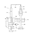
本発明の内燃機関の電子制御式弁駆動装置の発明を実施するための形態を、図1ないし図16を参照して詳細に説明する。図1は、本発明に係る内燃機関の電子制御式弁駆動装置を適用した電子制御式排気弁駆動装置の概略を示す外観図であり、図2は、図1に示した内燃機関の電子制御式排気弁駆動装置の概念図である。   An embodiment for carrying out the invention of an electronically controlled valve driving device for an internal combustion engine according to the present invention will be described in detail with reference to FIGS. FIG. 1 is an external view showing an outline of an electronically controlled exhaust valve driving device to which an electronically controlled valve driving device for an internal combustion engine according to the present invention is applied, and FIG. 2 is an electronic control of the internal combustion engine shown in FIG. It is a conceptual diagram of a type exhaust valve drive device.

図1及び図2に示すように、排気弁駆動装置20には、排気弁21と、排気弁21の弁軸21aの上端に取付けられて当該排気弁21を開弁させる油圧ピストン22と、弁軸21aの途中に取り付けられて排気弁21を閉弁(復旧動作)させる空気ばね24とが収容されている。   As shown in FIGS. 1 and 2, the exhaust valve driving device 20 includes an exhaust valve 21, a hydraulic piston 22 that is attached to the upper end of the valve shaft 21 a of the exhaust valve 21 and opens the exhaust valve 21, and a valve An air spring 24 that is attached in the middle of the shaft 21a and closes the exhaust valve 21 (restoring operation) is accommodated.

排気弁駆動装置20の上部20aには、油圧アクチュエータ25が取付けられている。この油圧アクチュエータ25は、油圧ピストン22を駆動するアクチュエータ機能と、油圧ピストン22の駆動速度を抑制するダンピング機能とを有しており、油路61を介して油圧ピストン22の油圧シリンダ23に接続されている。   A hydraulic actuator 25 is attached to the upper portion 20 a of the exhaust valve driving device 20. The hydraulic actuator 25 has an actuator function for driving the hydraulic piston 22 and a damping function for suppressing the driving speed of the hydraulic piston 22, and is connected to the hydraulic cylinder 23 of the hydraulic piston 22 via the oil passage 61. ing.

排気弁駆動装置20の側方には、この排気弁駆動装置20と別体の油圧ブロック30が配設され、当該油圧ブロック30には、方向制御弁31とアキュムレータ35が取り付けられている。また、方向制御弁31には、この方向制御弁31を切り替え制御するための電磁ソレノイド32が取り付けられている。   A hydraulic block 30 separate from the exhaust valve driving device 20 is disposed on the side of the exhaust valve driving device 20, and a directional control valve 31 and an accumulator 35 are attached to the hydraulic block 30. Further, an electromagnetic solenoid 32 for switching and controlling the direction control valve 31 is attached to the direction control valve 31.

油圧ブロック30内には油路30a,30b,30cが設けられ、方向制御弁31の図示しない対応するポートに接続されている。油圧源33は、油圧ポンプ34、アキュムレータ35などからなり、油圧ポンプ34は高圧管62を介して油路30aに接続され、アキュムレータ35は高圧管62に接続されている。   Oil passages 30a, 30b, and 30c are provided in the hydraulic block 30 and are connected to corresponding ports (not shown) of the direction control valve 31. The hydraulic source 33 includes a hydraulic pump 34, an accumulator 35, and the like. The hydraulic pump 34 is connected to the oil passage 30 a via a high pressure pipe 62, and the accumulator 35 is connected to the high pressure pipe 62.

油路30aは、油圧源33から高圧の油圧を方向制御弁31に導く。油路30bは、高圧管63を介して油圧アクチュエータ25に接続されている。油路30cは、方向制御弁31から低圧管64を介して油圧をタンク37に排出する。   The oil passage 30 a guides high pressure oil pressure from the oil pressure source 33 to the direction control valve 31. The oil passage 30 b is connected to the hydraulic actuator 25 via the high-pressure pipe 63. The oil passage 30 c discharges hydraulic pressure from the direction control valve 31 to the tank 37 through the low pressure pipe 64.

次に、油圧アクチュエータ25及びその内部に設けた流量制御ピストン41について説明する。図3は、図1に示した排気弁駆動装置20の上部20aと油圧アクチュエータ25の断面図を示し、図4は、図3に示した油圧アクチュエータ25の拡大図である。   Next, the hydraulic actuator 25 and the flow control piston 41 provided therein will be described. 3 is a cross-sectional view of the upper portion 20a of the exhaust valve driving device 20 and the hydraulic actuator 25 shown in FIG. 1, and FIG. 4 is an enlarged view of the hydraulic actuator 25 shown in FIG.

図3に示すように、油圧アクチュエータ25は、そのシリンダ26内にピストン27が摺動可能に収容されている。シリンダ26の油圧ピストン22側の端面には、排気弁装置20の油圧ピストン22の油路61に連通するポート(油路)26aが設けられ、方向制御弁31(図2参照)側の端面には、方向制御弁31に連通するポート(油路)26bが設けられている。   As shown in FIG. 3, the hydraulic actuator 25 has a piston 27 slidably accommodated in a cylinder 26 thereof. A port (oil passage) 26a communicating with the oil passage 61 of the hydraulic piston 22 of the exhaust valve device 20 is provided on the end face of the cylinder 26 on the hydraulic piston 22 side, and the end face on the direction control valve 31 (see FIG. 2) side is provided. Is provided with a port (oil passage) 26 b communicating with the direction control valve 31.

図4に示すように、ピストン27は、油圧ピストン22側の端面の中央位置に、弁リフト制御ピストン(流量制御ピストン)42を収容するためのピストン収容孔27aが設けられ、方向制御弁31側の端面の中央位置に、弁着座制御ピストン(流量制御ピストン)43を収容するためのピストン収容孔27bが設けられている。   As shown in FIG. 4, the piston 27 is provided with a piston accommodation hole 27 a for accommodating a valve lift control piston (flow rate control piston) 42 at the center position of the end face on the hydraulic piston 22 side, and the direction control valve 31 side. A piston accommodation hole 27b for accommodating a valve seating control piston (flow rate control piston) 43 is provided at the center position of the end face of the cylinder.

ピストン27には、一端がピストン27の油圧ピストン22(図2参照)側の端面に開口すると共に、他端がピストン収容孔27aに開口する1つ以上の、例えば2つのピストン油路27cと、一端がピストン27の方向制御弁31(図2参照)側の端面に開口すると共に、他端がピストン収容孔27bに開口する1つ以上の、例えば2つのピストン油路27dがそれぞれ設けられている。   The piston 27 has one end opened on the end surface of the piston 27 on the hydraulic piston 22 (see FIG. 2) side and the other end opened in the piston accommodating hole 27a, for example, two piston oil passages 27c, One or more, for example, two piston oil passages 27d each having one end opened on the end face of the piston 27 on the direction control valve 31 (see FIG. 2) side and the other end opened in the piston accommodation hole 27b are provided. .

ピストン27には、有底円筒形状をなすと共に、その底部に上述のピストン収容孔27bの端面開口位置よりも大径の油圧供給孔28aが設けられてなる大径ピストン28が、方向制御弁31側に摺動可能に外嵌されて、これにより二重ピストンを構成している。大径ピストン28は、シリンダ26内をピストン27と一体に、ピストン27のストロークよりも短い所定のストロークだけ移動可能である。大径ピストン28の油圧供給孔28aは、ピストン27に油圧を供給するためのものである。   The piston 27 has a cylindrical shape with a bottom, and a large-diameter piston 28 in which a hydraulic pressure supply hole 28a having a diameter larger than the end surface opening position of the piston accommodation hole 27b is provided in the bottom portion. It is slidably fitted to the side to form a double piston. The large diameter piston 28 can move within the cylinder 26 integrally with the piston 27 by a predetermined stroke shorter than the stroke of the piston 27. The hydraulic pressure supply hole 28 a of the large diameter piston 28 is for supplying hydraulic pressure to the piston 27.

油圧アクチュエータ25は、排気弁21(図2参照)の開弁当初はシリンダ内のガス圧が高いために大きな力が必要であり、このためポート26bに導入される高圧の油圧により大径ピストン28を用いて大きな油圧F1を発生させ、油圧F1をポート26aから油圧シリンダ23(図2参照)に供給する。大径ピストン28は、図4に示す位置から所定のストロークだけ移動し、図7に示す位置に停止する。この停止位置までは、ピストン27は大径ピストン28と一体になって移動する。   The hydraulic actuator 25 requires a large force because the gas pressure in the cylinder is high when the exhaust valve 21 (see FIG. 2) is initially opened. For this reason, the large-diameter piston 28 is driven by a high-pressure hydraulic pressure introduced into the port 26b. Is used to generate a large hydraulic pressure F1 and supply the hydraulic pressure F1 from the port 26a to the hydraulic cylinder 23 (see FIG. 2). The large-diameter piston 28 moves from the position shown in FIG. 4 by a predetermined stroke and stops at the position shown in FIG. Until this stop position, the piston 27 moves integrally with the large-diameter piston 28.

排気弁21が開弁を開始した後には、ピストン27により上記油圧F1よりも小さい油圧F2を発生させて、この油圧F2をポート26aから油圧シリンダ23に供給する。このとき、大径ピストン28は、図7に示す位置に停止している。これにより不要なピストンの作動をなくすことができ、排気弁21の開弁動作時における油圧の損失を抑えることができ、燃費の向上が図られる。   After the exhaust valve 21 starts to open, the piston 27 generates a hydraulic pressure F2 smaller than the hydraulic pressure F1 and supplies the hydraulic pressure F2 to the hydraulic cylinder 23 from the port 26a. At this time, the large-diameter piston 28 is stopped at the position shown in FIG. Accordingly, unnecessary piston operation can be eliminated, loss of hydraulic pressure during the opening operation of the exhaust valve 21 can be suppressed, and fuel consumption can be improved.

弁リフト制御ピストン42は、シリンダ26のポート26aに液密に嵌合可能とされ、基端部が大径とされ、先端部が滑らかなテーパをなして縮径されて、流量制御部42aとされる。流量制御部42aは、例えば大径の基端部側が内側にやや凹んだ凹テーパ状をなして、基端部から先端部にかけて縮径されている。   The valve lift control piston 42 can be liquid-tightly fitted to the port 26a of the cylinder 26, the base end portion has a large diameter, the tip end portion is reduced in diameter with a smooth taper, and the flow rate control portion 42a Is done. The flow rate control unit 42a has a concave taper shape in which, for example, the large-diameter base end portion is slightly recessed inward, and the diameter is reduced from the base end portion to the tip end portion.

弁着座制御ピストン43は、シリンダ26のポート26bに液密に嵌合可能とされ、また、基端部が大径とされると共に先端部が滑らかなテーパをなして縮径されて、流量制御部43aとされている。流量制御部43aは、例えば弁リフト制御ピストン42の流量制御部42aと同様に、大径の基端部側が内側にやや凹んだ凹テーパ状をなして、基端部から先端部にかけて縮径されている。   The valve seating control piston 43 can be fitted into the port 26b of the cylinder 26 in a liquid-tight manner, and the base end portion has a large diameter and the tip end portion is reduced in diameter with a smooth taper, thereby controlling the flow rate. Part 43a. The flow rate control unit 43a has a concave taper shape in which the large-diameter base end side is slightly recessed inward, similar to the flow rate control unit 42a of the valve lift control piston 42, for example, and the diameter is reduced from the base end portion to the tip end portion. ing.

図5(a),(b)に示すように、弁リフト制御ピストン42及び弁着座制御ピストン43は、ピストン収容孔27a,27bに摺動可能に収容でき、かつ端板44,45によって抜け出すことが防止されている。そして、弁リフト制御ピストン42と弁着座制御ピストン43の各基端部と、ピストン収容孔27a,27bの底端部との間に、スプリング46,47がそれぞれ縮設されている。これにより、弁リフト制御ピストン42及び弁着座制御ピストン43は、スプリング46,47の付勢力によりピストン27の端面から、それぞれ突出することができる。   As shown in FIGS. 5A and 5B, the valve lift control piston 42 and the valve seating control piston 43 can be slidably accommodated in the piston accommodation holes 27a and 27b, and come out by the end plates 44 and 45. Is prevented. Then, springs 46 and 47 are respectively contracted between the base end portions of the valve lift control piston 42 and the valve seating control piston 43 and the bottom end portions of the piston accommodation holes 27a and 27b. Thereby, the valve lift control piston 42 and the valve seating control piston 43 can project from the end face of the piston 27 by the urging force of the springs 46 and 47, respectively.

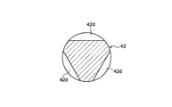
弁リフト制御ピストン42のピストン収容孔27aと摺動する円柱状の基端部は、図5(c)に示すように、スプリング46側の円周上の3か所が120°置きに面取り加工され、スプリング46側に軸方向に延びる3つの油路42dが形成されている。   As shown in FIG. 5C, the cylindrical base end portion that slides with the piston accommodation hole 27a of the valve lift control piston 42 is chamfered at intervals of 120 ° at three locations on the circumference of the spring 46 side. Thus, three oil passages 42d extending in the axial direction are formed on the spring 46 side.

弁着座制御ピストン43のピストン収容孔27bと摺動する円柱状の基端部は、図5(d)に示すように、スプリング47側の円周上の3か所が120°置きに面取り加工され、スプリング47側に軸方向に延びる3つの油路43dが形成されている。   As shown in FIG. 5D, the cylindrical base end portion that slides with the piston accommodation hole 27b of the valve seating control piston 43 is chamfered at intervals of 120 ° at three locations on the circumference on the spring 47 side. Thus, three oil passages 43d extending in the axial direction are formed on the spring 47 side.

弁リフト制御ピストン42及び弁着座制御ピストン43の、滑らかなテーパをなして縮径する流量制御部42a,43aは、弁リフト制御ピストン42及び弁着座制御ピストン43と液密にそれぞれ嵌合する油路との隙間面積、すなわち油圧アクチュエータ25のシリンダ26のポート26a,26b(図4参照)との隙間面積を、ピストン27の軸方向位置に応じて最適に調整することにより、後述するように、排気弁21のリフト時及び着座時におけるダンピング機能を持たせている。   The flow rate control units 42a and 43a of the valve lift control piston 42 and the valve seating control piston 43 that are reduced in diameter with a smooth taper are oils that are fitted into the valve lift control piston 42 and the valve seating control piston 43 in a liquid-tight manner, respectively. By adjusting the gap area with the path, that is, the gap area between the ports 26a and 26b (see FIG. 4) of the cylinder 26 of the hydraulic actuator 25, in accordance with the axial position of the piston 27, as described later, A damping function is provided when the exhaust valve 21 is lifted and seated.

また、弁リフト制御ピストン42及び弁着座制御ピストン43の内部には、一端がそれぞれの流量制御部42a,43aの先端部に開口すると共に、内部を軸方向に一定距離だけ直進した後に半径方向に、例えば2つに分岐して、他端が油圧アクチュエータ25のピストン27のピストン収容孔27a,27bに開口するピストン油路42b,43bが設けられている。   Further, one end of each of the valve lift control piston 42 and the valve seating control piston 43 is opened at the tip of each flow rate control unit 42a, 43a. For example, piston oil passages 42 b and 43 b are provided that branch into two and have the other ends opened to the piston accommodation holes 27 a and 27 b of the piston 27 of the hydraulic actuator 25.

ピストン油路42b,43bの他端の開口部42c,43cは、弁リフト制御ピストン42及び弁着座制御ピストン43の円柱状の外周部上に環状に形成されている。この一方、上述のピストン27のピストン油路27c,27dは、ピストン収容孔27a,27bに開口する開口部27e,27fが、ピストン収容孔27a,27bの内周部上に、それぞれ環状に形成されている。   The openings 42c and 43c at the other ends of the piston oil passages 42b and 43b are formed in an annular shape on the cylindrical outer peripheral portions of the valve lift control piston 42 and the valve seating control piston 43. On the other hand, in the piston oil passages 27c and 27d of the piston 27 described above, openings 27e and 27f that open to the piston accommodation holes 27a and 27b are respectively formed annularly on the inner peripheral portions of the piston accommodation holes 27a and 27b. ing.

この弁リフト制御ピストン42及び弁着座制御ピストン43のピストン油路42b,43bの開口部42c,43cと、ピストン27のピストン油路27c,27dの開口部27e,27fは、図5(a),(b)に示すように、弁リフト制御ピストン42及び弁着座制御ピストン43がピストン27から最も突出している状態では、軸方向位置がずれていて連通しない。   The opening portions 42c and 43c of the piston oil passages 42b and 43b of the valve lift control piston 42 and the valve seating control piston 43 and the opening portions 27e and 27f of the piston oil passages 27c and 27d of the piston 27 are shown in FIG. As shown in (b), in a state where the valve lift control piston 42 and the valve seating control piston 43 are most protruded from the piston 27, the axial position is shifted and the communication is not established.

しかし、この弁リフト制御ピストン42及び弁着座制御ピストン43のピストン油路42b,43bの開口部42c,43cと、ピストン27のピストン油路27c,27dの開口部27e,27fは、図6(a),(b)に示すように、弁リフト制御ピストン42及び弁着座制御ピストン43が、少なくともピストン27のピストン収容孔27a,27bに最も押し込まれている状態では、完全に連通するようになっている。   However, the openings 42c and 43c of the piston oil passages 42b and 43b of the valve lift control piston 42 and the valve seating control piston 43 and the openings 27e and 27f of the piston oil passages 27c and 27d of the piston 27 are shown in FIG. ), (B), the valve lift control piston 42 and the valve seating control piston 43 are in full communication with each other at least when they are pushed most into the piston receiving holes 27a and 27b of the piston 27. Yes.

つまり、弁リフト制御ピストン42及び弁着座制御ピストン43のピストン油路42b,43bと、ピストン27のピストン油路27c,27dは、弁リフト制御ピストン42及び弁着座制御ピストン43の軸方向位置に応じてそれぞれ連通する。この弁リフト制御ピストン42及び弁着座制御ピストン43のピストン油路42b,43bの開口部42c,43cから、主としてピストン27の移動初期に、ピストン27を押動するための油圧を供給する。   That is, the piston oil passages 42b and 43b of the valve lift control piston 42 and the valve seating control piston 43 and the piston oil passages 27c and 27d of the piston 27 correspond to the axial positions of the valve lift control piston 42 and the valve seating control piston 43. Communicate with each other. From the openings 42c and 43c of the piston oil passages 42b and 43b of the valve lift control piston 42 and the valve seating control piston 43, hydraulic pressure for pushing the piston 27 is supplied mainly at the initial stage of movement of the piston 27.

この一方、上述の弁リフト制御ピストン42の円周上の3か所に設けられた3つの油路42dと、ピストン27のピストン油路27cの開口部27eは、図5(a)及び図6(a)に示すように、弁リフト制御ピストン42の軸方向位置に係わりなく、常に連通している。また、弁着座制御ピストン43の円周上の3か所に設けられた3つの油路43dと、ピストン27のピストン油路27dの開口部27fは、図5(b)及び図6(b)に示すように、弁着座制御ピストン43の軸方向位置に係わりなく、常に連通している。   On the other hand, three oil passages 42d provided at three locations on the circumference of the above-described valve lift control piston 42 and the opening 27e of the piston oil passage 27c of the piston 27 are shown in FIGS. As shown in (a), the valve lift control piston 42 is always in communication regardless of the position in the axial direction. Also, three oil passages 43d provided at three locations on the circumference of the valve seating control piston 43 and the opening 27f of the piston oil passage 27d of the piston 27 are shown in FIGS. 5 (b) and 6 (b). As shown, the valve seating control piston 43 is always in communication regardless of the axial position.

このような構成により、弁リフト制御ピストン42は、後述するように、排気弁21が最大リフトに近づくと弁速度を減速させてオーバーシュートを確実に防止し、弁着座制御ピストン43は、排気弁21が着座する時に弁速度を減速させて滑らかに着座させて、ジャンピングを確実に防止する。   With such a configuration, as will be described later, the valve lift control piston 42 decelerates the valve speed when the exhaust valve 21 approaches the maximum lift to reliably prevent overshoot, and the valve seating control piston 43 When 21 is seated, the valve speed is reduced and seated smoothly to reliably prevent jumping.

次に、図2ないし図12に基づいて、排気弁駆動装置20の作動を説明する。図2に実線で示すように、排気弁21が閉弁しているとき、油圧アクチュエータ25のピストン27は、図3及び図4に示すように、ポート26b側の閉弁位置(終端位置)に停止している。そして、弁着座制御ピストン43の流量制御部43aが、図4に示すように、油圧アクチュエータ25のシリンダ26のポート26b内に液密に嵌合している。   Next, the operation of the exhaust valve driving device 20 will be described with reference to FIGS. As shown by the solid line in FIG. 2, when the exhaust valve 21 is closed, the piston 27 of the hydraulic actuator 25 is in the closed position (end position) on the port 26b side, as shown in FIGS. It has stopped. And the flow control part 43a of the valve seating control piston 43 is liquid-tightly fitted in the port 26b of the cylinder 26 of the hydraulic actuator 25 as shown in FIG.

排気弁21を開弁すべく、図示しない電子制御装置によりソレノイド弁32が駆動されると、ソレノイド弁32が方向制御弁31を開弁方向に駆動し、油圧源33の高圧の油圧が、油圧ブロック30を通して高圧管63に供給される。   When the solenoid valve 32 is driven by an electronic control device (not shown) to open the exhaust valve 21, the solenoid valve 32 drives the direction control valve 31 in the valve opening direction, and the high hydraulic pressure of the hydraulic source 33 is changed to the hydraulic pressure. The high pressure pipe 63 is supplied through the block 30.

方向制御弁31から高圧管63を通して供給された高圧の油圧は、油圧アクチュエータ25のシリンダ26のポート26bに供給されて、図5(b)及び図8(a)の矢印で示すように、弁着座制御ピストン43のピストン油路43bに圧力を加える。これにより、弁着座制御ピストン43は、図6(b)及び図8(b)に示すように、スプリング47のバネ力に抗してピストン収容孔27b内に押し込まれてその底部に当接する。   The high pressure hydraulic pressure supplied from the direction control valve 31 through the high pressure pipe 63 is supplied to the port 26b of the cylinder 26 of the hydraulic actuator 25, and as shown by the arrows in FIGS. 5 (b) and 8 (a). Pressure is applied to the piston oil passage 43b of the seating control piston 43. As a result, the valve seating control piston 43 is pushed into the piston accommodating hole 27b against the spring force of the spring 47 and abuts against the bottom thereof, as shown in FIGS.

このため、弁着座制御ピストン43のピストン油路43bの開口部43cと、ピストン27のピストン油路27dの開口部27fは連通し、ピストン油路43bの油圧がピストン油路27dを通して、ピストン27及び図4に示す大径ピストン28の端面にかかるようになる。これにより、ピストン27及び大径ピストン28が図示左方向に移動し始めると同時に、図8(c)に示すように、弁着座制御ピストン43の流量制御部43aが、シリンダ26のポート26bから抜け出す。   For this reason, the opening 43c of the piston oil passage 43b of the valve seating control piston 43 and the opening 27f of the piston oil passage 27d of the piston 27 communicate with each other, and the hydraulic pressure of the piston oil passage 43b passes through the piston oil passage 27d. It comes to the end surface of the large-diameter piston 28 shown in FIG. As a result, the piston 27 and the large-diameter piston 28 start to move in the left direction in the figure, and at the same time, the flow control unit 43a of the valve seating control piston 43 comes out of the port 26b of the cylinder 26 as shown in FIG. .

この流量制御部43aがテーパ状をなしていることで、ポート26bとの間の環状をなす隙間面積(開口面積)を通して、油圧がシリンダ26内に流入し、油圧がピストン27及び大径ピストン28の端面の全面にかかるようになる。これにより、ピストン27及び大径ピストン28が一体に、図示左方向に急速に移動する。   Since the flow rate control unit 43a is tapered, the hydraulic pressure flows into the cylinder 26 through an annular clearance area (opening area) between the port 26b and the hydraulic pressure flows into the piston 27 and the large-diameter piston 28. It comes to cover the whole end face of. As a result, the piston 27 and the large-diameter piston 28 move rapidly together in the left direction in the figure.

弁着座制御ピストン43がポート26bから完全に抜け出すと、ポート26bから大量の油圧がシリンダ26内に流入して、ピストン27と大径ピストン28とを一体に、大きな油圧で図中左方向にさらに急速に移動させる。図7に示すように、大径ピストン28のストロークは、ピストン27のストロークよりも短い。従って、ピストン27は、移動の初期に大きな油圧を発生させる。   When the valve seating control piston 43 is completely removed from the port 26b, a large amount of hydraulic pressure flows into the cylinder 26 from the port 26b, and the piston 27 and the large-diameter piston 28 are integrated into the left side in the figure with a large hydraulic pressure. Move rapidly. As shown in FIG. 7, the stroke of the large-diameter piston 28 is shorter than the stroke of the piston 27. Accordingly, the piston 27 generates a large hydraulic pressure at the initial stage of movement.

これと共に、図5(b)に示すように、大きな油圧が、ピストン油路27d及び弁着座制御ピストン43の油路43dを通してスプリング47側のピストン収容孔27b内にかかり、弁着座制御ピストン43に背圧を付与して、スプリング47と共働して、当該弁着座制御ピストン43を外側へ押し出す。これにより、弁着座制御ピストン43が元の状態に復帰する。   At the same time, as shown in FIG. 5 (b), a large hydraulic pressure is applied to the piston seating hole 27 b on the spring 47 side through the piston oil passage 27 d and the oil passage 43 d of the valve seating control piston 43. A back pressure is applied to cooperate with the spring 47 to push the valve seating control piston 43 outward. As a result, the valve seating control piston 43 returns to the original state.

油圧アクチュエータ25のピストン27の移動に伴い、シリンダ26内の油圧が、図2及び図3に示すポート26a及び油路61を通して油圧ピストン22を押し下げ、排気弁21を開弁させる。そして、図9(a)に示すように、ピストン27が終端近傍位置まで移動した後、図9(b)に示すように、弁リフト制御ピストン42の流量制御部42aがポート26a内に入り込む。   As the piston 27 of the hydraulic actuator 25 moves, the hydraulic pressure in the cylinder 26 pushes down the hydraulic piston 22 through the port 26a and the oil passage 61 shown in FIGS. 2 and 3 and opens the exhaust valve 21. Then, as shown in FIG. 9A, after the piston 27 moves to the position near the end, as shown in FIG. 9B, the flow rate control part 42a of the valve lift control piston 42 enters the port 26a.

この流量制御部42aがテーパ状をなしていることにより、ポート26aとの間の環状をなす隙間面積(開口面積)が徐々に小さくなり、図3に示す油圧ピストン22を駆動する油圧の流量が徐々に減少する。これに伴い、図2に示す排気弁21の開弁速度が減速される。   Since the flow rate control unit 42a is tapered, the annular gap area (opening area) with the port 26a is gradually reduced, and the flow rate of the hydraulic pressure for driving the hydraulic piston 22 shown in FIG. Decrease gradually. Accordingly, the opening speed of the exhaust valve 21 shown in FIG. 2 is reduced.

そして、図7及び図9(c)に示すように、ピストン27が終端位置まで移動して、弁リフト制御ピストン42がポート26aと液密に嵌合すると、図2に示す排気弁21が、当該図の2点鎖線で示す最大リフト位置(最大開弁位置)に停止する。   Then, as shown in FIGS. 7 and 9C, when the piston 27 moves to the end position and the valve lift control piston 42 is fluid-tightly fitted with the port 26a, the exhaust valve 21 shown in FIG. It stops at the maximum lift position (maximum valve opening position) indicated by the two-dot chain line in the figure.

弁リフト制御ピストン42による弁リフト側の油路(ポート26a)の面積変化の一例を、図10に示す。上述の弁リフト制御ピストン42は、排気弁21が最大リフト位置に近づくと弁速度を減速させて、排気弁21のオーバーシュートを確実に防止する。   An example of the area change of the oil passage (port 26a) on the valve lift side by the valve lift control piston 42 is shown in FIG. The valve lift control piston 42 described above reduces the valve speed when the exhaust valve 21 approaches the maximum lift position, and reliably prevents overshoot of the exhaust valve 21.

図2に示すように、排気弁21を閉弁すべく、図示しない電子制御装置により電磁ソレノイド32が駆動されると、方向制御弁31が閉弁方向に駆動され、高圧管63の油圧が方向制御弁31及び低圧管64を通してタンク37に排出される。これに伴い油圧アクチュエータ25のアクチュエータシリンダ26内の油圧が高圧管63に排出され、アクチュエータシリンダ26内の油圧が低下する。   As shown in FIG. 2, when the electromagnetic solenoid 32 is driven by an electronic control device (not shown) to close the exhaust valve 21, the direction control valve 31 is driven in the valve closing direction, and the hydraulic pressure in the high pressure pipe 63 is changed to the direction. It is discharged to the tank 37 through the control valve 31 and the low pressure pipe 64. Accordingly, the hydraulic pressure in the actuator cylinder 26 of the hydraulic actuator 25 is discharged to the high-pressure pipe 63, and the hydraulic pressure in the actuator cylinder 26 is reduced.

アクチュエータシリンダ26の油圧の低下に伴い、空気ばね24のばね力により油圧ピストン22が上方に移動し、油圧シリンダ23内の油圧がシリンダ26内に導入される。これに伴い、図5(a)の矢印で示すように、弁リフト制御ピストン42のピストン油路42bに圧力を加える。これにより、弁リフト制御ピストン42は、図6(a)に示すように、スプリング46のバネ力に抗してピストン収容孔27a内に押し込まれて、その底端部に当接する。   As the hydraulic pressure of the actuator cylinder 26 decreases, the hydraulic piston 22 moves upward by the spring force of the air spring 24, and the hydraulic pressure in the hydraulic cylinder 23 is introduced into the cylinder 26. Along with this, pressure is applied to the piston oil passage 42b of the valve lift control piston 42 as shown by the arrow in FIG. As a result, the valve lift control piston 42 is pushed into the piston accommodation hole 27a against the spring force of the spring 46, as shown in FIG.

弁リフト制御ピストン42がピストン収容孔27a内に押し込まれると、弁リフト制御ピストン42のピストン油路42bの開口部42cと、ピストン27のピストン油路27cの開口部27eとが連通し、弁リフト制御ピストン42のピストン油路42bにかかっていた油圧が、ピストン油路42bの油圧がピストン油路27cを通して、ピストン27の端面にかかるようになる。これにより、ピストン27が図示右方向に移動しはじめ、弁リフト制御ピストン42の流量制御部42aが、シリンダ26のポート26aから抜け始める。   When the valve lift control piston 42 is pushed into the piston accommodation hole 27a, the opening 42c of the piston oil passage 42b of the valve lift control piston 42 and the opening 27e of the piston oil passage 27c of the piston 27 communicate with each other, and the valve lift The oil pressure applied to the piston oil passage 42b of the control piston 42 is applied to the end surface of the piston 27 through the piston oil passage 27c. As a result, the piston 27 starts to move to the right in the figure, and the flow rate control unit 42a of the valve lift control piston 42 begins to come out of the port 26a of the cylinder 26.

この流量制御部42aがテーパ状をなしていることで、ポート26aとの間の環状をなす隙間面積(開口面積)を通して、油圧がシリンダ26内に流入し、油圧がピストン27の端面の全面にかかるようになる。これにより、ピストン27が図示右方向に急速に移動する。   Since the flow rate control unit 42a is tapered, the hydraulic pressure flows into the cylinder 26 through an annular clearance area (opening area) between the port 26a and the hydraulic pressure is applied to the entire end face of the piston 27. It becomes like this. Thereby, the piston 27 moves rapidly in the right direction in the figure.

ピストン27の右方向への移動と共に、弁リフト制御ピストン42の流量制御部42aがポート26aから完全に抜け出し、ポート26aとの間の隙間面積(開口面積)がさらに大きくなる。これにより、油圧シリンダ23からシリンダ26内に流入する油圧の流量がさらに増加し、ピストン27が図示右方向にさらに急速に移動する。   As the piston 27 moves to the right, the flow rate control unit 42a of the valve lift control piston 42 is completely removed from the port 26a, and the clearance area (opening area) between the port 27a and the port 27a is further increased. As a result, the flow rate of the hydraulic pressure flowing from the hydraulic cylinder 23 into the cylinder 26 further increases, and the piston 27 moves more rapidly in the right direction in the figure.

これと共に、図5(a)に示すように、大きな油圧が、ピストン油路27c及び弁リフト制御ピストン42の油路42dを通してスプリング46側のピストン収容孔27a内にかかり、弁リフト制御ピストン42に背圧を付与して、スプリング46と共働して、当該弁リフト制御ピストン42を外側へ押し出す。これにより、弁リフト制御ピストン42が元の状態に復帰する。   At the same time, as shown in FIG. 5 (a), a large hydraulic pressure is applied to the piston accommodation hole 27 a on the spring 46 side through the piston oil passage 27 c and the oil passage 42 d of the valve lift control piston 42 to the valve lift control piston 42. A back pressure is applied to cooperate with the spring 46 to push the valve lift control piston 42 outward. As a result, the valve lift control piston 42 returns to the original state.

排気弁21が着座位置(閉弁位置)に近づくと、図4に示すように、弁着座制御ピストン43の流量制御部43aがポート26bに入り込み、ポート26bとの間の隙間面積(開口面積)が徐々に小さくなる。これにより、ピストン27の移動速度が減速され、油圧シリンダ23からシリンダ26に流入する油圧の流量が徐々に減少する。   When the exhaust valve 21 approaches the seating position (valve closing position), as shown in FIG. 4, the flow rate control unit 43a of the valve seating control piston 43 enters the port 26b, and the clearance area (opening area) between the port 26b and the port 26b. Gradually decreases. Thereby, the moving speed of the piston 27 is decelerated, and the flow rate of the hydraulic pressure flowing into the cylinder 26 from the hydraulic cylinder 23 gradually decreases.

これに伴い、図2に示す排気弁21の開弁速度が減速される。そして、ピストン27が終端位置まで移動して、弁着座制御ピストン43がポート26bに液密に嵌合すると、排気弁21が、図2に2点鎖線で示すように着座する。図11に、弁着座制御ピストン43による弁着座側の油路(ポート26b)の面積変化の一例を示す。   Accordingly, the opening speed of the exhaust valve 21 shown in FIG. 2 is reduced. When the piston 27 moves to the end position and the valve seating control piston 43 is fluid-tightly fitted to the port 26b, the exhaust valve 21 is seated as shown by a two-dot chain line in FIG. FIG. 11 shows an example of a change in the area of the oil passage (port 26 b) on the valve seating side by the valve seating control piston 43.

弁着座制御ピストン43は、排気弁21が着座位置(閉弁位置)に近づくと、弁速度を減速させることにより排気弁21のジャンピングを確実に防止し、排気弁21が慣性力で弁シートに衝突することを防止する。これにより、図2に実線で示すように、排気弁21の滑らかな着座が行われる。このようにして、排気弁21の開弁動作及び閉弁動作が行われる。   When the exhaust valve 21 approaches the seating position (valve closing position), the valve seating control piston 43 reliably prevents jumping of the exhaust valve 21 by reducing the valve speed, and the exhaust valve 21 is applied to the valve seat by inertia force. Prevent collisions. Thereby, as shown by a solid line in FIG. 2, the smooth seating of the exhaust valve 21 is performed. Thus, the valve opening operation and the valve closing operation of the exhaust valve 21 are performed.

このように、排気弁21が最大リフト位置(開弁位置)に近づくと、弁リフト制御ピストン42により弁速度を減速させる。また、排気弁21が着座位置(閉弁位置)に近づくと、弁着座制御ピストン43により弁速度を減速させることにより、図10に示すような弁の作動特性を得ることができる。図10において、曲線部Aは排気弁21のリフト時を示し、曲線部Bは着座時を示している。   As described above, when the exhaust valve 21 approaches the maximum lift position (valve opening position), the valve speed is reduced by the valve lift control piston 42. Further, when the exhaust valve 21 approaches the seating position (valve closing position), the valve operating speed is reduced by the valve seating control piston 43, whereby the valve operating characteristics as shown in FIG. 10 can be obtained. In FIG. 10, a curved portion A indicates when the exhaust valve 21 is lifted, and a curved portion B indicates when the exhaust valve 21 is seated.

また、油圧アクチュエータ25は、ダンピング機能とアクチュエータ機能とを併せ持つものであり、応答性が非常に高い。したがって、高圧管63等の高圧配管系内が負圧となりにくく、高圧配管系のキャビテーション・エロージョンの発生を抑えることができる。   The hydraulic actuator 25 has both a damping function and an actuator function, and has very high responsiveness. Accordingly, the inside of the high-pressure piping system such as the high-pressure pipe 63 is unlikely to become negative pressure, and the occurrence of cavitation erosion in the high-pressure piping system can be suppressed.

図13及び図14は、弁リフト制御ピストン及び弁着座制御ピストンからなる流量制御ピストンの、構成に関する他の実施形態を示す。上述の弁リフト制御ピストン42及び弁着座制御ピストン43の場合と同様の部分は、同じ符号を以って説明する。   13 and 14 show another embodiment relating to the configuration of the flow rate control piston including the valve lift control piston and the valve seating control piston. Portions similar to those in the above-described valve lift control piston 42 and valve seating control piston 43 will be described with the same reference numerals.

油圧アクチュエータ125は、そのシリンダ126内にピストン127が摺動可能に収容されている。ピストン127は、油圧ピストン22側の端面の中央位置に、弁リフト制御ピストン(流量制御ピストン)142を収容するためのピストン収容孔127aが設けられ、方向制御弁31側の端面の中央位置に、弁着座制御ピストン(流量制御ピストン)143を収容するためのピストン収容孔127bが設けられている。   The hydraulic actuator 125 has a piston 127 slidably accommodated in a cylinder 126 thereof. The piston 127 is provided with a piston accommodation hole 127a for accommodating a valve lift control piston (flow rate control piston) 142 at the center position of the end face on the hydraulic piston 22 side, and at the center position of the end face on the direction control valve 31 side. A piston accommodation hole 127b for accommodating the valve seating control piston (flow rate control piston) 143 is provided.

ピストン127には、一端がピストン127の油圧ピストン22側の端面に開口すると共に、他端がピストン収容孔127aに開口するピストン油路127cと、一端がピストン127の方向制御弁31側の端面に開口すると共に、他端がピストン収容孔127bに開口するピストン油路127dとがそれぞれ設けられている。   The piston 127 has one end opened on the end surface of the piston 127 on the hydraulic piston 22 side and the other end opened on the piston accommodation hole 127a, and one end on the end surface of the piston 127 on the direction control valve 31 side. A piston oil passage 127d having an opening and the other end opening to the piston accommodation hole 127b is provided.

ピストン127には、有底円筒形状をなすと共に、その底部に上述のピストン収容孔127bの端面開口位置よりも大径の油圧供給孔128aが設けられてなる大径ピストン128が、方向制御弁31側に摺動可能に外嵌されて、これにより二重ピストンを構成している。大径ピストン128及びピストン127は、上述の油圧アクチュエータ25の大径ピストン28及びピストン27と同様に作動する。   The piston 127 has a cylindrical shape with a bottom, and a large-diameter piston 128 in which a hydraulic pressure supply hole 128a having a diameter larger than the end surface opening position of the piston accommodation hole 127b is provided in the bottom portion of the piston 127. It is slidably fitted to the side to form a double piston. The large diameter piston 128 and the piston 127 operate in the same manner as the large diameter piston 28 and the piston 27 of the hydraulic actuator 25 described above.

また、弁リフト制御ピストン142の流量制御部142a及び弁着座制御ピストン143の流量制御部143aの外観は、上述の油圧アクチュエータ25の流量制御部42a,43aと同様に形成されるが、流量制御部142a,143aは中実に形成されて、その内部にピストン油路が形成されていない点において異なる。弁リフト制御ピストン142及び弁着座制御ピストン143は、ピストン収容孔127a,127bに摺動可能に収容され、かつ端板144,145によって抜け出すことが防止されている。   Further, the flow rate control unit 142a of the valve lift control piston 142 and the flow rate control unit 143a of the valve seating control piston 143 are formed in the same manner as the flow rate control units 42a and 43a of the hydraulic actuator 25 described above. 142a and 143a are formed in a solid shape, and are different in that a piston oil passage is not formed therein. The valve lift control piston 142 and the valve seating control piston 143 are slidably accommodated in the piston accommodation holes 127a and 127b, and are prevented from coming out by the end plates 144 and 145.

弁リフト制御ピストン142と弁着座制御ピストン143の各基端部と、ピストン収容孔127a,127bの底端部との間に、スプリング146,147がそれぞれ縮設されている。これにより、弁リフト制御ピストン142及び弁着座制御ピストン143は、ピストン27の端面からそれぞれ突出することができる。   Springs 146 and 147 are respectively contracted between the base ends of the valve lift control piston 142 and the valve seating control piston 143 and the bottom ends of the piston receiving holes 127a and 127b. Thereby, the valve lift control piston 142 and the valve seating control piston 143 can each protrude from the end surface of the piston 27.

ピストン127のピストン油路127c,127dは、これらスプリング146,147が縮設された状態で、弁リフト制御ピストン142及び弁着座制御ピストン143の軸方向位置に拘わらず、常にピストン収容孔127a及びピストン収容孔127bにそれぞれ連通している。   The piston oil passages 127c and 127d of the piston 127 are always in the state in which the springs 146 and 147 are contracted, regardless of the axial positions of the valve lift control piston 142 and the valve seating control piston 143. Each communicates with the accommodation hole 127b.

次に、図2,図13及び図14に基づいて、この排気弁駆動装置の作動を説明する。図2に実線で示すように、排気弁21が閉弁しているとき、油圧アクチュエータ125のピストン127は、図13に示すように、ポート126b側の閉弁位置(終端位置)に停止している。そして、弁着座制御ピストン143がポート126b内に液密に嵌合している。   Next, the operation of the exhaust valve driving device will be described with reference to FIGS. As shown by the solid line in FIG. 2, when the exhaust valve 21 is closed, the piston 127 of the hydraulic actuator 125 stops at the valve closed position (end position) on the port 126b side as shown in FIG. Yes. The valve seating control piston 143 is liquid-tightly fitted in the port 126b.

排気弁21を開弁すべく、方向制御弁31から高圧管63を通して供給された高圧の油圧は、油圧アクチュエータ125のシリンダ126のポート126bに供給されて、弁着座制御ピストン143が、スプリング147のバネ力に抗してピストン収容孔127b内に押し込まれる。   The high pressure oil pressure supplied from the direction control valve 31 through the high pressure pipe 63 to open the exhaust valve 21 is supplied to the port 126b of the cylinder 126 of the hydraulic actuator 125, and the valve seating control piston 143 is connected to the spring 147. It is pushed into the piston accommodation hole 127b against the spring force.

弁着座制御ピストン143は、この押動に伴い、流量制御部143aがシリンダ126のポート126bから抜け出す。流量制御部143aは、テーパ状をなしていることで、ポート126bとの間の環状をなす隙間面積(開口面積)が徐々に大きくなり、これに伴いシリンダ126内に流入する油圧の流量が増加し、ピストン127及び大径ピストン128の端面に徐々に油圧がかかるようになる。これにより、ピストン127及び大径ピストン128が図示左方向に移動しはじめる。   As the valve seating control piston 143 is pushed, the flow rate control unit 143a comes out of the port 126b of the cylinder 126. Since the flow rate control unit 143a has a tapered shape, an annular gap area (opening area) between the port 126b and the port 126b gradually increases, and the flow rate of hydraulic pressure flowing into the cylinder 126 increases accordingly. Then, the hydraulic pressure is gradually applied to the end surfaces of the piston 127 and the large-diameter piston 128. As a result, the piston 127 and the large-diameter piston 128 begin to move in the left direction in the figure.

弁着座制御ピストン143がポート126bから完全に抜け出すと、ポート126bから大量の油圧がシリンダ126内に流入して、ピストン127と大径ピストン128とを一体に、大きな油圧で図中左方向に急速に移動させる。シリンダ126内に油圧が流入すると、その一部がピストン油路127dを通してピストン収容孔127b内に流入し、弁着座制御ピストン143に背圧を付与して、スプリング147と共働して当該弁着座制御ピストン143を押し出す。これにより、弁着座制御ピストン143が元の状態に復帰する。   When the valve seating control piston 143 is completely removed from the port 126b, a large amount of hydraulic pressure flows into the cylinder 126 from the port 126b, and the piston 127 and the large-diameter piston 128 are integrated into a large body and rapidly moved to the left in the figure. Move to. When the hydraulic pressure flows into the cylinder 126, a part thereof flows into the piston accommodation hole 127b through the piston oil passage 127d, applies back pressure to the valve seating control piston 143, and cooperates with the spring 147 to apply the valve seating. The control piston 143 is pushed out. As a result, the valve seating control piston 143 returns to the original state.

ピストン127が図中左方向にさらに移動すると、図14に示すように、弁リフト制御ピストン142の流量制御部142aがポート126a内に入り込む。流量制御部142aはテーパ状をなしていることにより、ポート126aとの間の環状をなす隙間面積(開口面積)が徐々に小さくなり、油圧ピストン22を駆動する油圧の流量が徐々に減少する。   When the piston 127 further moves leftward in the figure, the flow rate control unit 142a of the valve lift control piston 142 enters the port 126a as shown in FIG. Since the flow rate control unit 142a is tapered, an annular clearance area (opening area) with the port 126a is gradually reduced, and the flow rate of the hydraulic pressure for driving the hydraulic piston 22 is gradually reduced.

これに伴い、排気弁21の開弁速度が減速される。そして、ピストン127が終端位置まで移動して、弁リフト制御ピストン142がポート126aと液密に嵌合すると、排気弁21が、図2の2点鎖線で示す最大リフト位置(最大開弁位置)に停止する。   Accordingly, the valve opening speed of the exhaust valve 21 is reduced. When the piston 127 moves to the end position and the valve lift control piston 142 is fluid-tightly fitted with the port 126a, the exhaust valve 21 is at the maximum lift position (maximum valve opening position) indicated by the two-dot chain line in FIG. To stop.

図2及び図14に示すように、排気弁21を閉弁すべく、図示しない電子制御装置により電磁ソレノイド32が駆動されると、方向制御弁31が閉弁方向に駆動され、高圧管63の油圧が方向制御弁31及び低圧管64を通してタンク37に排出される。これに伴い油圧アクチュエータ125のアクチュエータシリンダ126内の油圧が高圧管63に排出され、アクチュエータシリンダ126内の油圧が低下する。   As shown in FIGS. 2 and 14, when the electromagnetic solenoid 32 is driven by an electronic control device (not shown) to close the exhaust valve 21, the direction control valve 31 is driven in the valve closing direction, and the high-pressure pipe 63 is closed. The hydraulic pressure is discharged to the tank 37 through the direction control valve 31 and the low pressure pipe 64. As a result, the hydraulic pressure in the actuator cylinder 126 of the hydraulic actuator 125 is discharged to the high pressure pipe 63, and the hydraulic pressure in the actuator cylinder 126 decreases.

アクチュエータシリンダ126の油圧の低下に伴い、空気ばね24のばね力により油圧ピストン22が上方に移動し、油圧シリンダ23内の油圧がシリンダ126内に導入される。これに伴い、弁リフト制御ピストン142が、スプリング146のバネ力に抗してピストン収容孔127a内に押し込まれる。   As the hydraulic pressure of the actuator cylinder 126 decreases, the hydraulic piston 22 moves upward by the spring force of the air spring 24, and the hydraulic pressure in the hydraulic cylinder 23 is introduced into the cylinder 126. Accordingly, the valve lift control piston 142 is pushed into the piston accommodation hole 127a against the spring force of the spring 146.

弁リフト制御ピストン142がピストン収容孔127a内に押し込まれると、弁リフト制御ピストン142とポート126aとの隙間から、油圧がピストン127に徐々にかかり、ピストン127が図示右方向に移動しはじめる。ピストン127の右方向への移動と共に、弁リフト制御ピストン142の流量制御部142aがポート126aから抜け出し、ポート126aとの間の隙間面積(開口面積)が徐々に大きくなる。これにより、油圧シリンダ23からシリンダ126内に流入する油圧の流量が増加し、ピストン127が急速に図示右方向に移動する。   When the valve lift control piston 142 is pushed into the piston accommodation hole 127a, the hydraulic pressure is gradually applied to the piston 127 through the gap between the valve lift control piston 142 and the port 126a, and the piston 127 starts to move rightward in the drawing. As the piston 127 moves to the right, the flow rate control unit 142a of the valve lift control piston 142 comes out of the port 126a, and the clearance area (opening area) between the port 126a and the port 126a gradually increases. As a result, the flow rate of the hydraulic pressure flowing from the hydraulic cylinder 23 into the cylinder 126 increases, and the piston 127 rapidly moves to the right in the figure.

排気弁21が着座位置(閉弁位置)に近づくと、弁着座制御ピストン143の流量制御部143aが、図13に示すように、ポート126bに入り込み、ポート126bとの間の隙間面積(開口面積)が徐々に小さくなる。これにより、ピストン127の移動速度が減速され、油圧シリンダ23からシリンダ126に流入する油圧の流量が徐々に減少する。   When the exhaust valve 21 approaches the seating position (valve closing position), the flow control unit 143a of the valve seating control piston 143 enters the port 126b as shown in FIG. 13, and the clearance area (opening area) between the port 126b and the port 126b is reached. ) Gradually decreases. Thereby, the moving speed of the piston 127 is decelerated, and the flow rate of the hydraulic pressure flowing into the cylinder 126 from the hydraulic cylinder 23 gradually decreases.

これに伴い、排気弁21の開弁速度が減速される。そして、弁着座制御ピストン143がポート126bに液密に嵌合すると、排気弁21が、図2に2点鎖線で示すように着座する。弁着座制御ピストン143は、排気弁21が着座位置(閉弁位置)に近づくと、弁速度を減速させることにより排気弁21のジャンピングを確実に防止し、排気弁21が慣性力で弁シートに衝突することを防止する。これにより、図2に実線で示すように、排気弁21の滑らかな着座が行われる。このようにして、排気弁21の開弁動作及び閉弁動作が行われる。その他は、上述の油圧アクチュエータ25の場合と同様であるから、説明を省略する。   Accordingly, the valve opening speed of the exhaust valve 21 is reduced. When the valve seating control piston 143 is fluid-tightly fitted to the port 126b, the exhaust valve 21 is seated as shown by a two-dot chain line in FIG. When the exhaust valve 21 approaches the seating position (valve closing position), the valve seating control piston 143 reliably prevents the exhaust valve 21 from jumping by reducing the valve speed, and the exhaust valve 21 is applied to the valve seat by inertia force. Prevent collisions. Thereby, as shown by a solid line in FIG. 2, the smooth seating of the exhaust valve 21 is performed. Thus, the valve opening operation and the valve closing operation of the exhaust valve 21 are performed. The rest is the same as in the case of the hydraulic actuator 25 described above, and a description thereof will be omitted.

図15及び図16は、弁リフト制御ピストン及び弁着座制御ピストンからなる流量制御ピストンの、流量制御部の形状に関する他の実施形態を示す。   15 and 16 show another embodiment relating to the shape of the flow rate control unit of the flow rate control piston including the valve lift control piston and the valve seating control piston.

上述の流量制御ピストン41の流量制御部42a,43aは、基端部側が内側にやや凹んだ凹テーパ状をなして基端部から先端部にかけて縮径するように形成されているのに対し、図15に示す流量制御ピストン148の流量制御部148aは、外側にやや膨らんだ凸テーパ状をなして、基端部から先端部にかけて縮径するように形成されたものである。また、図16に示す流量制御ピストン149の流量制御部149aは、大径の基端部から直線的な円錐台形状のテーパ面をなして、基端部から先端部に向って縮径するように形成されたものである。   The flow rate control portions 42a and 43a of the flow rate control piston 41 described above are formed so that the proximal end side is formed in a concave taper shape that is slightly recessed inward, and the diameter is reduced from the proximal end portion to the distal end portion. The flow rate control portion 148a of the flow rate control piston 148 shown in FIG. 15 has a convex taper shape slightly bulging outward, and is formed so as to decrease in diameter from the proximal end portion to the distal end portion. Further, the flow rate control unit 149a of the flow rate control piston 149 shown in FIG. 16 forms a linear truncated cone-shaped tapered surface from the large-diameter base end so that the diameter decreases from the base end toward the front end. It is formed.

なお、流量制御ピストンの流量制御部は、上述した直線的なテーパ面や外側に膨出する曲面や内側に凹む曲面に限るものではなく、様々な形状に設定することが可能である。また、この流量制御部の形状は、例えば図10及び図11に示すような油路の面積変化のグラフから最適な設定することができる。   The flow rate control unit of the flow rate control piston is not limited to the above-described linear taper surface, a curved surface bulging outward, or a curved surface recessed inward, and can be set in various shapes. Moreover, the shape of this flow control part can be optimally set from the graph of the area change of an oil passage as shown, for example in FIG.10 and FIG.11.

上述の内燃機関の電子制御式弁駆動装置は一例にすぎず、本発明の趣旨に基づいて種々の変形が可能であり、それらを本発明の範囲から排除するものではない。   The above-described electronically controlled valve drive device for an internal combustion engine is merely an example, and various modifications can be made based on the spirit of the present invention, and they are not excluded from the scope of the present invention.

本発明は、内燃機関の電子制御式弁駆動装置に限定して利用されるものではなく、様々な内燃機関の弁駆動装置や油圧機構に対しても利用することができることは勿論である。   The present invention is not limited to an electronically controlled valve drive device for an internal combustion engine, and can of course be used for various internal combustion engine valve drive devices and hydraulic mechanisms.

20 排気弁駆動装置
20a 上部
21 排気弁
21a 弁軸
22 油圧ピストン
23 油圧シリンダ
24 空気ばね
25 油圧アクチュエータ
26 シリンダ
26a,26b ポート
27 ピストン
27a,27b ピストン収容孔
27c,27d ピストン油路
27e,27f 開口部
28 大径ピストン
28a 油圧供給孔
30 油圧ブロック
30a,30b,30c 油路
31 方向制御弁
32 ソレノイド弁
33 油圧源
34 油圧ポンプ
35 アキュームレータ
37 タンク
41 流量制御ピストン
42 弁リフト制御ピストン(流量制御ピストン)
42a 流量制御部
42b ピストン油路
42c 開口部
42d 油路
43 弁着座制御ピストン(流量制御ピストン)
43a 流量制御部
43b ピストン油路
43c 開口部
43d 油路
44,45 端板
46,47 スプリング
61 油路
62,63 高圧管
64 低圧管
125 油圧アクチュエータ
126 シリンダ
126a,126b ポート
127 ピストン
127a,127b ピストン収容孔
127c,127d ピストン油路
128 大径ピストン
128a 油圧供給孔
141 流量制御ピストン
142 弁リフト制御ピストン(流量制御ピストン)
142a 流量制御部
143 弁着座制御ピストン(流量制御ピストン)
143a 流量制御部
144,145 端板
146,147 スプリング
148,149 流量制御ピストン
148a,149a 流量制御部
201 電子制御式排気弁駆動装置
202 排気弁
203 ソレノイド弁
204 方向制御弁
205 油圧ポンプ
206 アキュームレータ
207 油圧源
208,209,212 高圧管
210 低圧管
211 油圧アクチュエータ
213 油圧シリンダ
214 油圧ピストン
215 ダンパ
216 空気ばね
217 タンク
221 弁
222 油圧ピストン
225 ダンピング・アクチュエータ
227 アクチュエータピストン
231 方向制御弁
233 油圧供給手段
240,241 逆止弁
242,243 バイパス油路
20 Exhaust valve drive device 20a Upper part 21 Exhaust valve 21a Valve shaft 22 Hydraulic piston 23 Hydraulic cylinder 24 Air spring 25 Hydraulic actuator 26 Cylinder 26a, 26b Port 27 Piston 27a, 27b Piston accommodating hole 27c, 27d Piston oil passage 27e, 27f Opening 28 Large-diameter piston 28a Hydraulic supply hole 30 Hydraulic block 30a, 30b, 30c Oil passage 31 Direction control valve 32 Solenoid valve 33 Hydraulic source 34 Hydraulic pump 35 Accumulator 37 Tank 41 Flow control piston 42 Valve lift control piston (flow control piston)
42a Flow control unit 42b Piston oil passage 42c Opening 42d Oil passage 43 Valve seating control piston (flow control piston)
43a Flow control unit 43b Piston oil passage 43c Opening 43d Oil passage 44, 45 End plate 46, 47 Spring 61 Oil passage 62, 63 High pressure pipe 64 Low pressure pipe 125 Hydraulic actuator 126 Cylinder 126a, 126b Port 127 Piston 127a, 127b Piston housing Hole 127c, 127d Piston oil passage 128 Large diameter piston 128a Hydraulic supply hole 141 Flow rate control piston 142 Valve lift control piston (flow rate control piston)
142a Flow Control Unit 143 Valve Seat Control Piston (Flow Control Piston)
143a Flow control units 144, 145 End plates 146, 147 Springs 148, 149 Flow control pistons 148a, 149a Flow control unit 201 Electronically controlled exhaust valve drive device 202 Exhaust valve 203 Solenoid valve 204 Directional control valve 205 Hydraulic pump 206 Accumulator 207 Hydraulic pressure Source 208, 209, 212 High pressure pipe 210 Low pressure pipe 211 Hydraulic actuator 213 Hydraulic cylinder 214 Hydraulic piston 215 Damper 216 Air spring 217 Tank 221 Valve 222 Hydraulic piston 225 Damping actuator 227 Actuator piston 231 Directional control valve 233 Hydraulic supply means 240, 241 Check valves 242, 243 Bypass oil passage

Claims (8)

内燃機関の弁駆動装置(20)に収容された弁(21)に取付けられて当該弁を開弁させる油圧ピストン(22)と、前記油圧ピストンに油圧を供給する油圧発生手段(33)と、前記油圧発生手段からの油圧を前記油圧ピストンに供給し又は前記油圧ピストンの油圧を排出する方向制御弁(31)と、前記方向制御弁と前記油圧ピストンとの間に接続されて前記方向制御弁により供給又は排出される油圧により前記油圧ピストンを駆動する油圧アクチュエータ(25)と、前記油圧アクチュエータの内部に設けられて前記弁のリフト時に前記油圧ピストンに供給する油圧の流量を制御すると共に前記弁の着座時に前記油圧ピストンから排出させる油圧の流量を制御して前記油圧ピストンの駆動速度を抑制する流量制御ピストン(41,141)とを備えた内燃機関の電子制御式弁駆動装置において、前記流量制御ピストンは、前記油圧アクチュエータのピストン(27,127)の前記油圧ピストン側の端面に設けられた弁リフト制御ピストン(42,142)と、前記油圧アクチュエータのピストンの前記方向制御弁側の端面に設けられた弁着座制御ピストン(43,143)とからなり、前記弁リフト制御ピストン及び弁着座制御ピストンは、前記油圧アクチュエータの前記ピストンの端面に設けられたピストン収容孔(27a、27b,127a、127b)に入出可能に収容されると共にこれらのピストン収容孔の底端部とピストンの基端部との間に縮設されたスプリング(46,47,146,147)により前記ピストンの端面から突出していることを特徴とする内燃機関の電子制御式弁駆動装置。 A hydraulic piston (22) attached to a valve (21) housed in a valve drive device (20) of an internal combustion engine to open the valve; a hydraulic pressure generating means (33) for supplying hydraulic pressure to the hydraulic piston; A directional control valve (31) for supplying the hydraulic pressure from the hydraulic pressure generating means to the hydraulic piston or discharging the hydraulic pressure of the hydraulic piston, and the directional control valve connected between the directional control valve and the hydraulic piston. A hydraulic actuator (25) for driving the hydraulic piston by hydraulic pressure supplied or discharged by the valve, and a flow rate of the hydraulic pressure provided in the hydraulic actuator to be supplied to the hydraulic piston when the valve is lifted. The flow rate control pistons (41, 14) which control the flow rate of the hydraulic pressure discharged from the hydraulic piston when seated, and suppress the driving speed of the hydraulic piston. ) And the electronically controlled valve drive for an internal combustion engine wherein the flow control piston, said hydraulic piston-side valve lift control piston provided on the end face of the hydraulic actuator piston (27, 127) (42, 142) and a valve seating control piston (43, 143) provided on the end face on the direction control valve side of the piston of the hydraulic actuator, and the valve lift control piston and the valve seating control piston are the same as those of the hydraulic actuator. The piston is accommodated in a piston accommodation hole (27a, 27b, 127a, 127b) provided in the end face of the piston so as to be able to enter and exit, and is contracted between the bottom end portion of the piston accommodation hole and the base end portion of the piston. spring (46,47,146,147) by inner, characterized in that protrudes from an end face of the piston Electronically controlled valve actuating device of the engine. 内燃機関の弁駆動装置(20)に収容された弁(21)に取付けられて当該弁を開弁させる油圧ピストン(22)と、前記油圧ピストンに油圧を供給する油圧発生手段(33)と、前記油圧発生手段からの油圧を前記油圧ピストンに供給し又は前記油圧ピストンの油圧を排出する方向制御弁(31)と、前記方向制御弁と前記油圧ピストンとの間に接続されて前記方向制御弁により供給又は排出される油圧により前記油圧ピストンを駆動する油圧アクチュエータ(25)と、前記油圧アクチュエータの内部に設けられて前記弁のリフト時に前記油圧ピストンに供給する油圧の流量を制御すると共に前記弁の着座時に前記油圧ピストンから排出させる油圧の流量を制御して前記油圧ピストンの駆動速度を抑制する流量制御ピストン(41,141)とを備えた内燃機関の電子制御式弁駆動装置において、前記流量制御ピストンは、前記油圧アクチュエータのピストン(27,127)の前記油圧ピストン側の端面に設けられた弁リフト制御ピストン(42,142)と、前記油圧アクチュエータのピストンの前記方向制御弁側の端面に設けられた弁着座制御ピストン(43,143)とからなり、前記弁リフト制御ピストンは、前記油圧ピストンに連通する油路(26a,126a)に液密に嵌合可能とされると共に先端部が滑らかに縮径されて流量制御部(42a,142a)とされ、前記弁着座制御ピストンは、前記方向制御弁に連通する油路(26b,126b)に液密に嵌合可能とされると共に先端部が滑らかに縮径されて流量制御部(43a,143a)とされ、前記弁リフト制御ピストンの前記流量制御部及び前記弁着座制御ピストンの前記流量制御部は、内側に凹んだ凹テーパ状をなして基端部から先端部にかけて縮径されるように形成されていることを特徴とする内燃機関の電子制御式弁駆動装置。 A hydraulic piston (22) attached to a valve (21) housed in a valve drive device (20) of an internal combustion engine to open the valve; a hydraulic pressure generating means (33) for supplying hydraulic pressure to the hydraulic piston; A directional control valve (31) for supplying the hydraulic pressure from the hydraulic pressure generating means to the hydraulic piston or discharging the hydraulic pressure of the hydraulic piston, and the directional control valve connected between the directional control valve and the hydraulic piston. A hydraulic actuator (25) for driving the hydraulic piston by hydraulic pressure supplied or discharged by the valve, and a flow rate of the hydraulic pressure provided in the hydraulic actuator to be supplied to the hydraulic piston when the valve is lifted. The flow rate control pistons (41, 14) which control the flow rate of the hydraulic pressure discharged from the hydraulic piston when seated, and suppress the driving speed of the hydraulic piston. ) And the electronically controlled valve drive for an internal combustion engine wherein the flow control piston, said hydraulic piston-side valve lift control piston provided on the end face of the hydraulic actuator piston (27, 127) (42, 142) and a valve seating control piston (43, 143) provided on the end face of the piston of the hydraulic actuator on the direction control valve side, and the valve lift control piston communicates with the hydraulic piston ( 26a, 126a) can be fitted in a fluid-tight manner, and the tip end portion is smoothly reduced in diameter to form a flow rate control unit (42a, 142a), and the valve seating control piston communicates with the directional control valve. The passage (26b, 126b) can be fitted in a fluid-tight manner, and the tip portion is smoothly reduced in diameter to form a flow rate control unit (43a, 143a). The flow control unit of the flow rate control unit and the valve seating control piston bet control piston, that it is formed so as to be reduced in diameter toward the distal end portion from the proximal end forms a concave tapered recessed inwardly An electronically controlled valve drive device for an internal combustion engine. 前記弁リフト制御ピストン(42,142)は、前記油圧ピストンに連通する油路(26a,126a)に液密に嵌合可能とされると共に先端部が滑らかに縮径されて流量制御部(42a,142a)とされ、前記弁着座制御ピストン(43,143)は、前記方向制御弁に連通する油路(26b,126b)に液密に嵌合可能とされると共に先端部が滑らかに縮径されて流量制御部(43a,143a)とされていることを特徴とする請求項に記載の内燃機関の電子制御式弁駆動装置。 The valve lift control pistons (42, 142) can be fluid-tightly fitted into oil passages (26a, 126a) communicating with the hydraulic pistons, and the tip portions thereof are smoothly reduced in diameter so that the flow rate control unit (42a). 142a), and the valve seating control piston (43, 143) can be fluid-tightly fitted in an oil passage (26b, 126b) communicating with the directional control valve, and the tip portion can be smoothly reduced in diameter. The electronically controlled valve drive device for an internal combustion engine according to claim 1 , wherein the flow control unit (43a, 143a) is used. 前記弁リフト制御ピストン(42,142)及び弁着座制御ピストン(43,143)は、これらのピストンと嵌合する前記油路との隙間面積を前記油圧アクチュエータのピストンの軸方向位置に応じて変化させて前記流量制御部(42a,43a,142a,143a)により前記油圧ピストン(22)に供給する油圧の流量と前記油圧ピストンから排出される油圧の流量を制御することを特徴とする請求項2又は3に記載の内燃機関の電子制御式弁駆動装置。 The valve lift control pistons (42, 142) and the valve seating control pistons (43, 143) change the clearance area between the pistons of the hydraulic actuators according to the axial positions of the hydraulic actuators. The flow rate controller (42a, 43a, 142a, 143a) controls the flow rate of hydraulic pressure supplied to the hydraulic piston (22) and the flow rate of hydraulic pressure discharged from the hydraulic piston. Or an electronically controlled valve drive device for an internal combustion engine according to 3; 前記弁リフト制御ピストン(42,142)及び弁着座制御ピストン(43,143)は、前記油圧アクチュエータのピストンの端面に設けられたピストン収容孔(27a、27b,127a、127b)に入出可能に収容されると共にこれらのピストン収容孔の底端部とピストンの基端部との間に縮設されたスプリング(46,47,146,147)により前記ピストンの端面から突出していることを特徴とする請求項に記載の内燃機関の電子制御式弁駆動装置。 The valve lift control piston (42, 142) and the valve seating control piston (43, 143) are accommodated in a piston accommodation hole (27a, 27b, 127a, 127b) provided in the end face of the piston of the hydraulic actuator. And a spring (46, 47, 146, 147) which is contracted between the bottom end of the piston receiving hole and the base end of the piston, and protrudes from the end face of the piston. An electronically controlled valve drive device for an internal combustion engine according to claim 2 . 前記弁リフト制御ピストン(42)には、一端が前記流量制御部(42a)の先端部に開口すると共に他端が前記油圧アクチュエータ(25)のピストン(27)の前記ピストン収容孔(27a)に開口するピストン油路(42b,42c)が設けられ、前記油圧アクチュエータのピストンには、一端が当該ピストンの前記弁リフト制御ピストン側の端面に開口すると共に他端が前記ピストン収容孔に開口して前記弁リフト制御ピストンの軸方向位置に応じて前記弁リフト制御ピストンの前記ピストン油路に連通するピストン油路(27c)が設けられていることを特徴とする請求項3又は5に記載の内燃機関の電子制御式弁駆動装置。 One end of the valve lift control piston (42) opens at the tip of the flow rate control unit (42a), and the other end of the valve lift control piston (42) enters the piston accommodation hole (27a) of the piston (27) of the hydraulic actuator (25). Open piston oil passages (42b, 42c) are provided, and one end of the piston of the hydraulic actuator opens to the end face of the piston on the valve lift control piston side, and the other end opens to the piston accommodation hole. 6. The internal combustion engine according to claim 3 , wherein a piston oil passage (27 c) communicating with the piston oil passage of the valve lift control piston is provided according to an axial position of the valve lift control piston. An electronically controlled valve drive for an engine. 前記弁着座制御ピストン(43)には、一端が前記流量制御部(43a)の先端部に開口すると共に他端が前記油圧アクチュエータ(25)のピストン(27)の前記ピストン収容孔(27b)に開口するピストン油路(43b,43c)が設けられ、前記油圧アクチュエータのピストンには、一端が当該ピストンの前記弁着座制御ピストン側の端面に開口すると共に他端が前記ピストン収容孔に開口して前記弁着座制御ピストンの軸方向位置に応じて前記弁着座制御ピストンの前記ピストン油路に連通するピストン油路(27d)が設けられていることを特徴とする請求項3又は5に記載の内燃機関の電子制御式弁駆動装置。 One end of the valve seating control piston (43) opens at the tip of the flow rate control section (43a) and the other end of the valve seating control piston (43) is in the piston accommodation hole (27b) of the piston (27) of the hydraulic actuator (25). Piston oil passages (43b, 43c) are provided, and one end of the piston of the hydraulic actuator opens to the end surface of the piston on the valve seating control piston side, and the other end opens to the piston accommodation hole. The internal combustion engine according to claim 3 or 5 , wherein a piston oil passage (27d) communicating with the piston oil passage of the valve seating control piston is provided according to an axial position of the valve seating control piston. An electronically controlled valve drive for an engine. 前記弁リフト制御ピストン(42)の前記流量制御部(42a)及び前記弁着座制御ピストン(43)の前記流量制御部(43a)は、内側に凹んだ凹テーパ状をなして基端部から先端部にかけて縮径されるように形成されていることを特徴とする請求項に記載の内燃機関の電子制御式弁駆動装置。
The flow rate control part (42a) of the valve lift control piston (42) and the flow rate control part (43a) of the valve seating control piston (43) have a concave taper shape that is recessed inwardly, and the distal end from the base end part. 4. The electronically controlled valve drive device for an internal combustion engine according to claim 3 , wherein the valve is formed so as to be reduced in diameter toward the portion.
JP2010192245A 2010-08-30 2010-08-30 Electronically controlled valve drive device for internal combustion engine Expired - Fee Related JP5571509B2 (en)

Priority Applications (1)

Application Number Priority Date Filing Date Title
JP2010192245A JP5571509B2 (en) 2010-08-30 2010-08-30 Electronically controlled valve drive device for internal combustion engine

Applications Claiming Priority (1)

Application Number Priority Date Filing Date Title
JP2010192245A JP5571509B2 (en) 2010-08-30 2010-08-30 Electronically controlled valve drive device for internal combustion engine

Publications (2)

Publication Number Publication Date
JP2012047151A JP2012047151A (en) 2012-03-08
JP5571509B2 true JP5571509B2 (en) 2014-08-13

Family

ID=45902282

Family Applications (1)

Application Number Title Priority Date Filing Date
JP2010192245A Expired - Fee Related JP5571509B2 (en) 2010-08-30 2010-08-30 Electronically controlled valve drive device for internal combustion engine

Country Status (1)

Country Link
JP (1) JP5571509B2 (en)

Families Citing this family (1)

* Cited by examiner, † Cited by third party
Publication number Priority date Publication date Assignee Title
DE102013207863A1 (en) * 2013-04-30 2014-10-30 Mahle International Gmbh Device for controlling a gas exchange valve of an internal combustion engine

Family Cites Families (6)

* Cited by examiner, † Cited by third party
Publication number Priority date Publication date Assignee Title
JPH0791969B2 (en) * 1989-03-20 1995-10-09 川崎重工業株式会社 Valve drive for internal combustion engine
JPH0726923A (en) * 1993-07-07 1995-01-27 Zexel Corp Valve control device for internal combustion engine
JPH0749011A (en) * 1993-08-05 1995-02-21 Nippon Soken Inc Hydraulic valve opening/closing mechanism
JP2910583B2 (en) * 1994-10-31 1999-06-23 株式会社島津製作所 Fuel control valve
US6474277B1 (en) * 1999-09-16 2002-11-05 Diesel Engine Retarders, Inc. Method and apparatus for valve seating velocity control
JP4321447B2 (en) * 2004-11-26 2009-08-26 いすゞ自動車株式会社 Valve drive apparatus for internal combustion engine

Also Published As

Publication number Publication date
JP2012047151A (en) 2012-03-08

Similar Documents

Publication Publication Date Title
JP4994455B2 (en) Fluid working machine and valve configuration
JP4286770B2 (en) Control valve and fuel injection valve having the same
US7302920B2 (en) Variable valve actuator
KR101952958B1 (en) Adjustable damping valve device with an emergency valve
KR101484794B1 (en) Attenuator for damping pressure fluctuations in a hydraulic system
US6135073A (en) Hydraulic check valve recuperation
CN104704210A (en) Hybrid cam-camless variable valve actuation system
JP4641521B2 (en) Variable turbocharger and driving method thereof
CN107567535B (en) Actuator for axial movement of an object
CN105864471A (en) Control valve with annular poppet check valve
CN102588031B (en) Hydraulic engine valve actuation system including independent feedback control
JP5571509B2 (en) Electronically controlled valve drive device for internal combustion engine
JP2006342731A (en) Fuel injector for internal combustion engine
EP3406891B1 (en) A fuel valve for large turbocharged two stroke diesel engines
US8607751B2 (en) Electro-hydraulic variable valve lift system
US6857618B2 (en) Device for controlling a gas exchange valve
JP2005528564A5 (en)
JP5127747B2 (en) Electronically controlled valve drive device for internal combustion engine
KR101946098B1 (en) A hydraulic valve arrangement for controllably operating a gas exchange valve of an internal combustion piston engine
EP2206940A1 (en) Valve actuator
US20040144345A1 (en) Device for controlling charge exchange valves
JP2010209747A (en) Electronically controlled valve driving device of internal combustion engine
FI122257B (en) Hydraulic actuator
US20080092967A1 (en) Control valve assembly
JP5470180B2 (en) Control valve

Legal Events

Date Code Title Description
A621 Written request for application examination

Free format text: JAPANESE INTERMEDIATE CODE: A621

Effective date: 20130321

A977 Report on retrieval

Free format text: JAPANESE INTERMEDIATE CODE: A971007

Effective date: 20140128

A131 Notification of reasons for refusal

Free format text: JAPANESE INTERMEDIATE CODE: A131

Effective date: 20140225

A521 Written amendment

Free format text: JAPANESE INTERMEDIATE CODE: A523

Effective date: 20140415

TRDD Decision of grant or rejection written
A01 Written decision to grant a patent or to grant a registration (utility model)

Free format text: JAPANESE INTERMEDIATE CODE: A01

Effective date: 20140527

A61 First payment of annual fees (during grant procedure)

Free format text: JAPANESE INTERMEDIATE CODE: A61

Effective date: 20140626

R150 Certificate of patent or registration of utility model

Ref document number: 5571509

Country of ref document: JP

Free format text: JAPANESE INTERMEDIATE CODE: R150

LAPS Cancellation because of no payment of annual fees