JP5568718B2 - Electronic article monitoring system with metal detection capability and method therefor - Google Patents
Electronic article monitoring system with metal detection capability and method therefor Download PDFInfo
- Publication number
- JP5568718B2 JP5568718B2 JP2011517405A JP2011517405A JP5568718B2 JP 5568718 B2 JP5568718 B2 JP 5568718B2 JP 2011517405 A JP2011517405 A JP 2011517405A JP 2011517405 A JP2011517405 A JP 2011517405A JP 5568718 B2 JP5568718 B2 JP 5568718B2
- Authority
- JP
- Japan
- Prior art keywords
- eas
- metal
- voltage
- signal
- metal body
- Prior art date
- Legal status (The legal status is an assumption and is not a legal conclusion. Google has not performed a legal analysis and makes no representation as to the accuracy of the status listed.)
- Active
Links
Images


Classifications
-
- G—PHYSICS
- G08—SIGNALLING
- G08B—SIGNALLING OR CALLING SYSTEMS; ORDER TELEGRAPHS; ALARM SYSTEMS
- G08B13/00—Burglar, theft or intruder alarms
- G08B13/22—Electrical actuation
- G08B13/24—Electrical actuation by interference with electromagnetic field distribution
-
- G—PHYSICS
- G01—MEASURING; TESTING
- G01V—GEOPHYSICS; GRAVITATIONAL MEASUREMENTS; DETECTING MASSES OR OBJECTS; TAGS
- G01V15/00—Tags attached to, or associated with, an object, in order to enable detection of the object
-
- G—PHYSICS
- G08—SIGNALLING
- G08B—SIGNALLING OR CALLING SYSTEMS; ORDER TELEGRAPHS; ALARM SYSTEMS
- G08B13/00—Burglar, theft or intruder alarms
- G08B13/22—Electrical actuation
- G08B13/24—Electrical actuation by interference with electromagnetic field distribution
- G08B13/2402—Electronic Article Surveillance [EAS], i.e. systems using tags for detecting removal of a tagged item from a secure area, e.g. tags for detecting shoplifting
- G08B13/2465—Aspects related to the EAS system, e.g. system components other than tags
- G08B13/248—EAS system combined with another detection technology, e.g. dual EAS and video or other presence detection system
Description
(関連出願の相互参照)
本発明は、2008年7月7日に出願された、「INCORPORATION OF METAL/MAGNET DETECTION MECHANISM IN ACOUSTIC EAS SYSTEMS」と題する米国仮出願番号第61/134,137に関連し、これに対する優先権を主張し、その全体の内容は参照により本明細書に組み込まれる。
(Cross-reference of related applications)
The present invention relates to and claims priority to US Provisional Application No. 61 / 134,137, filed July 7, 2008, entitled “INCORPORATION OF METAL / MAGNET DETECTION MECHANASM IN ACOUSTIC EAS SYSTEMS”. The entire contents of which are hereby incorporated by reference.
本発明は、概して、電子物品監視(「EAS」)システムに関連し、より具体的には、音響EASシステムにおいて、金属検出器または磁気検出器を組み込むための方法およびシステムに関連する。 The present invention relates generally to electronic article surveillance ("EAS") systems, and more specifically to methods and systems for incorporating metal detectors or magnetic detectors in acoustic EAS systems.
電子物品監視(「EAS」)システムは、保護区域から許可されていない物品が持ち出されることを防止するため、一般的に小売店や別の環境で使用される。典型的には、検出システムは、保護区域の出口に設定され、「問い合わせ区域」として知られている、出口を横切って電磁場を発生させることができる1つ以上の送信器およびアンテナ(「ペデスタル」)を備えている。保護されるべき物品は、EASマーカでタグ付けされ、有効化されると、この問い合わせ区域を通過したときに応答信号を発する。同一または別の「ペデスタル」にあるアンテナおよび受信器は、この応答信号を検出し、警報を発生させる。 Electronic article surveillance ("EAS") systems are commonly used in retail stores and other environments to prevent the removal of unauthorized articles from protected areas. Typically, the detection system is set at the exit of a protected area and is known as an “interrogation area”, one or more transmitters and antennas (“pedestals”) that can generate an electromagnetic field across the exit. ). The article to be protected is tagged with an EAS marker and, when activated, issues a response signal when it passes through this query area. An antenna and receiver in the same or another “pedestal” detect this response signal and generate an alarm.
音響磁気式(「AM」)のEASシステムでは、EASマーカの鍵となる有効な要素は、溶融鋳造のアモルファスの磁気リボンでできた1つ以上のストリップである。マーカの内部で特定の磁気バイアスの状況下に置かれたとき、これらのストリップは、その固有共振周波数で電磁場のエネルギーを受信し、蓄える。 In an acoustomagnetic ("AM") EAS system, the key effective element of the EAS marker is one or more strips made of melt cast amorphous magnetic ribbon. When placed under certain magnetic bias conditions inside the marker, these strips receive and store the energy of the electromagnetic field at its natural resonant frequency.
結果として、検出システムの送信器から送信されたエネルギー源が途切れると、マーカが信号源となり、その共振周波数で電磁エネルギーを放射することができる。このような信号は、送信場が存在しないため、たとえ微弱でも受信器により直ちに検出され得る。 As a result, when the energy source transmitted from the transmitter of the detection system is interrupted, the marker becomes a signal source and can radiate electromagnetic energy at its resonant frequency. Such a signal can be detected immediately by the receiver, even if it is weak, because there is no transmission field.
このプロセスの特性により、EASマーカまたは送信器に接近した他の磁性材料または金属は、EASシステムの最適な性能に干渉する場合がある。金属材料および磁性材料を検出するための従来のシステムは、例えば、米国特許第4,709,213号の「Metal Detector Having Digital Signal Processing」、米国特許第5,414,411号の「Pulse Induction Metal Detector」、および米国特許出願公報第2007/0046288号の「Hybrid―Technology Metal Detector」が知られている。 Due to the nature of this process, EAS markers or other magnetic materials or metals close to the transmitter may interfere with the optimal performance of the EAS system. Conventional systems for detecting metallic and magnetic materials are described, for example, in US Pat. No. 4,709,213, “Metal Detector Having Digital Signal Processing”, US Pat. No. 5,414,411, “Pulse Induction Metal”. Detector "and" Hybrid-Technology Metal Detector "of US Patent Application Publication No. 2007/0046288 are known.
また、EASシステムを備えた金属検出を使用するための先行のシステムは一般的に提案されており、例えば、欧州特許第EP0736850号の「Method for preventing shoplifting and electronic theft detection system」がある。しかし、このようなシステムはEASシステムに隣接した金属検出システムを単に提供しているに過ぎず、実際にこれらを1つのシステムに統合させるという、向上した効率性およびコスト削減のためのどんなメカニズムも提供していない。 Also, prior systems for using metal detection with an EAS system have been generally proposed, for example, “Method for presenting shopping and electrical theft detection system” of European Patent No. EP 0 734 850. However, such a system merely provides a metal detection system adjacent to the EAS system, and any mechanism for improved efficiency and cost reduction that actually integrates them into one system. Not provided.
それゆえ、金属検出がEASシステム内で結合的に統合された金属検出の機能性により達成され得るシステムが必要とされる。 Therefore, there is a need for a system in which metal detection can be achieved with metal detection functionality that is jointly integrated within the EAS system.
本発明は、電子物品監視(「EAS」)システムの問い合わせ区域内で金属体を検出するための方法およびシステムを有利に提供する。一般的に、金属体は、EASマーカを検出するために使用される同一の機器を使用して検出される。金属検出サイクルおよびEASマーカ検出サイクルは、経時的に、周期的に組み入れられる。 The present invention advantageously provides a method and system for detecting metal objects within an interrogation zone of an electronic article surveillance ("EAS") system. In general, the metal body is detected using the same equipment used to detect the EAS marker. The metal detection cycle and EAS marker detection cycle are incorporated periodically over time.
本発明の一態様によると、EASシステムを使用して金属を検出するための方法が提供される。EASシステムは、送信器および受信器を備える。EAS問い合わせ信号は、問い合わせ区域を確立するように送信される。EAS問い合わせ信号は、問い合わせ区域内でEASマーカおよび金属体を検出するために使用される。金属検出サイクルの間に、EAS信号が受信され、かつ問い合わせ区域内の金属体の存在が検出される。金属体は、受信したEAS問い合わせ信号の摂動に基づき検出される。金属検出サイクルは、少なくとも1回のEAS検出サイクルとともに、周期的に組み入れられる。 According to one aspect of the invention, a method is provided for detecting metals using an EAS system. The EAS system includes a transmitter and a receiver. The EAS inquiry signal is sent to establish an inquiry area. The EAS inquiry signal is used to detect EAS markers and metal objects within the inquiry area. During the metal detection cycle, an EAS signal is received and the presence of a metal body in the interrogation zone is detected. The metal body is detected based on the perturbation of the received EAS inquiry signal. The metal detection cycle is incorporated periodically with at least one EAS detection cycle.
本発明の別の態様によると、電子物品監視のためのシステムは、送信器、受信器、および金属検出器を備える。送信器は、EAS問い合わせ信号を送信するように動作可能である。EAS問い合わせ信号は、問い合わせ区域を確立し、問い合わせ区域内のEASマーカおよび金属体を検出するために使用される。受信器は、EAS問い合わせ信号を受信するように動作可能である。金属検出器は、金属検出サイクルの間に、EASシステムに接近した金属体を検出するように動作可能である。金属体は、受信したEAS問い合わせ信号の摂動に基づいて検出される。金属検出サイクルは、少なくとも1回のEAS検出サイクルとともに、周期的に組み入れられる。 According to another aspect of the invention, a system for electronic article monitoring comprises a transmitter, a receiver, and a metal detector. The transmitter is operable to send an EAS inquiry signal. The EAS inquiry signal is used to establish an inquiry area and to detect EAS markers and metal objects in the inquiry area. The receiver is operable to receive an EAS inquiry signal. The metal detector is operable to detect metal objects that are close to the EAS system during the metal detection cycle. The metal body is detected based on the perturbation of the received EAS inquiry signal. The metal detection cycle is incorporated periodically with at least one EAS detection cycle.
本発明のさらに別の態様によると、金属検出システムは、送信器、受信器、および金属検出器を備える。送信器は、送信窓の間に電磁信号を生成するように動作可能である。電磁信号は問い合わせ区域を確立し、問い合わせ区域内のEASマーカおよび金属体を検出するために使用される。受信器は、検出窓の間にEASマーカから受信した信号を検出するように動作可能である。金属検出器は、金属体により作り出された電磁信号の摂動に基づいて、送信窓の間に、問い合わせ区域に接近した金属体を検出するように動作可能である。 According to yet another aspect of the invention, a metal detection system comprises a transmitter, a receiver, and a metal detector. The transmitter is operable to generate an electromagnetic signal during the transmission window. The electromagnetic signal establishes an inquiry area and is used to detect EAS markers and metal objects in the inquiry area. The receiver is operable to detect a signal received from the EAS marker during the detection window. The metal detector is operable to detect a metal body approaching the interrogation zone during the transmission window based on perturbation of the electromagnetic signal created by the metal body.
添付の図面を併せて考慮すると、以下の詳細な説明を参照することにより、本発明のより完全なる理解、そして結果として伴うその有利性および特徴が、より容易に理解されるであろう。 A more complete understanding of the present invention, and the attendant advantages and features thereof, will be more readily understood by reference to the following detailed description when considered in conjunction with the accompanying drawings.
本発明による例示的な実施形態を詳細に説明する前に、実施形態は主として、金属検出の機能性を電子物品監視(「EAS」)システム内に、結合的に統合するためのシステムおよび方法の実施に関連した装置の構成部品およびプロセスステップを組み合わせて備えていることに注意されたい。従って、システムおよび方法の構成要素は、適切な場合は図面において従来の記号を用いて表示され、本明細書の記載による利益を有する当業者にとって、容易に明らかとなる詳細をもって開示を不明確にしないために、本発明の実施形態の理解に関連するこれらの特定の詳細のみを示す。 Before describing exemplary embodiments in accordance with the present invention in detail, the embodiments will primarily focus on systems and methods for jointly integrating metal detection functionality into an electronic article surveillance ("EAS") system. Note that the equipment components and process steps associated with the implementation are provided in combination. Accordingly, the components of the system and method will be indicated using conventional symbols in the drawings where appropriate, and will obscure the disclosure with details that will be readily apparent to those of ordinary skill in the art having the benefit of this description. Only those specific details relevant to an understanding of embodiments of the present invention are shown.
本明細書で使用される場合、「第1」および「第2」、「頂部」および「底部」等のような関係を示す言葉は、1つの実体または要素を、別の実体または要素と単に区別するためにのみ使用され得、いかなる物理的若しくは論理的な関係、又は、そのような実体若しくは要素の順序を必ずしも必要とせず又は暗示しない。 As used herein, terms indicating relationships such as "first" and "second", "top" and "bottom" etc. simply refer to one entity or element as another entity or element. It can only be used to distinguish and does not necessarily require or imply any physical or logical relationship, or the order of such entities or elements.
本発明の一実施形態は、EASシステムの問い合わせ区域で金属を検出するための方法およびシステムを有利に提供する。EASシステムは、EASタグを検出するために使用される同一のハードウェアを使用して、金属の存在を検出する。 One embodiment of the present invention advantageously provides a method and system for detecting metals in the interrogation zone of an EAS system. The EAS system detects the presence of metal using the same hardware used to detect the EAS tag.
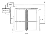
ここで、同様の参照指示が同様の要素を示す図面を参照すると、図1には、本発明の原理により構築され、かつ、例えば施設の入り口に配置された、例示的なEAS検出システム10の一構成が示される。EAS検出システム10は、入り口14の対向しあう側面に一対のペデスタル12a、12b(併せてペデスタル12と呼ぶ)を含む。EAS検出システム10のための、1つ以上のアンテナがペデスタル12aおよび12bに含まれてもよく、これらは既知の距離だけ離れて配置される。ペデスタル12に配置されたアンテナは、EAS検出システム10の動作を制御する制御システム16に電気的に連結される。システム制御器16は、箔を裏打ちした袋の存在をより的確に検出するために、磁場検出器17に選択で電気的に接続されてもよい。システム制御器16と連結した磁場検出器17の動作は以下のさらに詳細に論じる。
Referring now to the drawings in which like reference instructions indicate like elements, FIG. 1 illustrates an exemplary
次に図2を参照すると、例示的なEAS制御システムは、制御器18(例えば、プロセッサまたはマイクロプロセッサ)、電源20、トランシーバ22、メモリ24(不揮発性メモリ、揮発性メモリ、またはその組み合わせを含んでもよい)、通信インターフェース26、および警報器28を含んでもよい。制御器18は、無線通信、メモリ24へのデータの記憶、記憶されたデータの別のデバイスへの通信、および警報器28の起動を制御する。バッテリーまたはAC電源のような電源20は、EAS制御システム16に電力を供給する。警報器28は、EASシステム10の問い合わせ区域内でのEASマーカおよび/または金属の検出に対応して、可視的および/または可聴的な警報を提供するため、ソフトウェアおよびハードウェアを備えてもよい。
Referring now to FIG. 2, an exemplary EAS control system includes a controller 18 (eg, a processor or microprocessor), a
トランシーバ22は、1つ以上の送信アンテナ32に電気的に連結された送信器30、および1つ以上の受信アンテナ36に電気的に連結された受信器34を備えてもよい。交互に、単一のアンテナまたは一対のアンテナが、送信アンテナ32および受信アンテナ36の両方として使用されてもよい。送信器30は、EASシステム10の問い合わせ区域内のEASマーカを「活性化する」ため、送信アンテナ32を使用して無線周波数の信号を送信する。受信器34は、受信アンテナ36を使用してEASマーカの応答信号を検出する。
The
メモリ24は、問い合わせ区域内で金属の存在を検出するために金属検出モジュール38を含んでもよい。金属検出モジュール38の動作は、以下でさらに詳細に説明する。
The
次に図3を参照すると、一つのEASシステムの例示的な検出サイクル40のタイミング図が示されている。EASマーカの固有の特性を利用して、EAS検出システムは、1回の時間周期中にバーストを送信することができ、次いで、1回の検出サイクル40の間の次のタイムフレームで応答信号を「聞く」。一実施形態では、EAS検出サイクル40は、送信窓42、タグ検出窓44、同期窓46、およびノイズ窓48の、4つの別々の時間周期を備える。例示的な検出サイクル40は、周波数が90Hzならば、11.1ミリ秒の間である。検出サイクル40の開始において、58kHzの電磁(「EM」)場の1.6ミリ秒間のバースト、すなわち無線周波数信号が、同じ58kHzの周波数の固有共振周波数を有するEASマーカを「活性化する」ため、送信窓42の間に送信される。送信窓42の終わりには、EASマーカは、既に相当な量のエネルギーを受信し、かつ蓄えており、それにより実際のEASマーカは、蓄えたエネルギーを徐々に消散(一般的に「リングダウン」として知られる)しながら、58kHzで共振するエネルギー/信号源となる。送信されたEM場は、EASマーカ信号よりも数桁大きくてもよい。結果として、受信器34は送信の間は動作しない。受信器34は、送信器30がEMエネルギーの送信を停止した後に、EASマーカ信号の存在を「聞き」始める。タグ検出窓44の間に、EASマーカ信号は、バックグラウンドが静かである時、すなわち送信器30がオフ状態の時に、容易に検出することができる。確認目的のため、受信器34は、同期窓46の間およびノイズ窓48の間、すなわち、それぞれEMエネルギーのバーストの送信完了の3.9ミリ秒後および5.5ミリ秒後にもまた再度聞く。この時までに、EASマーカのエネルギーは、ほぼ完全に消散しているはずであり、検出され得ない。しかし、信号がまだ存在する場合、それはある未知の干渉源の存在を示し、警報器28は無効化される。
Referring now to FIG. 3, a timing diagram for an
次に図4を参照すると、本発明の一実施形態において、金属検出サイクル50は、送信窓42に代わって金属検出窓52を備える。金属検出サイクル50の残りの部分は、最初の検出サイクル40と同一、すなわちタグ検出窓44、同期窓46、およびノイズ窓48である。金属を検出するための一つ方法は、EM励起の間の、誘導された渦電流に基づく。誘導された渦電流は、良好な導体の場合、およそ数十マイクロ秒で非常に迅速に消散する。不良な導体だと消散率が悪い。良好な導体を用いたとしても、渦電流の消散は音響マーカの消散よりも約2桁短い。
Referring now to FIG. 4, in one embodiment of the present invention, the
EAS検出システム10は、金属検出送信サイクル50の終了後にマーカの検出を再開する。この場合、同一のEM励起の送信が、図4で示されるように、金属および音響EASマーカの両方の存在を検出するために使用されてもよい。
The
金属検出の間、1つのペデスタルだけが送信ペデスタルとして使用されることが理解される。結果として、この混成サイクルの間における検出は、両方のペデスタルが同時に送信する、EASのみのサイクルにおける検出と比較して減少され得る。しかし、多様な方法で異なるサイクルを混合することができる。例えば図5で示されるように、混成サイクル54は、EASのみの検出サイクル40の3回ごとに対し1回の金属検出サイクル50を含んでもよい。図5で示される、EASのみの検出サイクル40ごとに組み入れられた金属検出サイクル50の順序および量は、単に図解目的のためであることに注意されたい。サイクルのいかなる組み合わせおよび/または順序も、本発明の範囲内にある。
It is understood that during metal detection, only one pedestal is used as the transmitting pedestal. As a result, detection during this hybrid cycle can be reduced compared to detection in an EAS-only cycle where both pedestals transmit simultaneously. However, different cycles can be mixed in a variety of ways. For example, as shown in FIG. 5, the
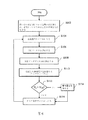
次に図6を参照すると、金属を検出するための金属検出モジュール38およびトランシーバ22により遂行される例示的なステップを説明するフローチャートが提供されている。この方法は、EM励起の間に誘導された渦電流を検出することに基づく。本発明の一実施形態は、エネルギーを送信するために片方のペデスタルのみを使用する一方、他方のペデスタルが金属検出のための受信アンテナ36として役目を果たす。金属検出モジュール38は、問い合わせ区域において、送信アンテナ32を介してEMエネルギーのバーストを送信することにより、受信アンテナ36で金属の存在無しに発生した基準電圧(Vr)を決定し、かつ、受信アンテナ36で誘導された電圧を測定する(ステップS102)。金属検出サイクル50の送信窓52の間に、金属の存在無しに受信アンテナ36のセンスコイルに発生した誘導された電圧(Vr)は、送信EM場に起因してかなり大きい。
Referring now to FIG. 6, a flowchart is provided illustrating exemplary steps performed by the
金属検出モジュール38がバックグラウンドの電圧Vrを決定すると、システム10は金属検出サイクル50に入り得る(ステップS104)。金属検出サイクル50の間に、EMエネルギーのバーストは送信アンテナ32を介して送信され(ステップS106)、そして受信アンテナで受信される(ステップS108)。一般的に、金属が問い合わせ区域に存在する場合、渦電流効果に起因する受信した信号の強さは、EM場を送信している間に誘導された直接誘導電圧よりもかなり小さい。金属が存在するとき、誘導された電圧は、Vmの値まで低下する。金属の存在の結果、受信した正味の実効電圧(Vs)は、Vr−Vmで計算され(ステップS110)、これはVrのほんのわずかな部分(数パーセント程度)である。Vsが所定の閾値の電圧(VTH)よりも大きい場合(ステップS112)、金属検出モジュールは警報器を始動させる(ステップS114)。警報器は可聴的または可視的な警報器でもよく、あるいは金属がEAS検出システム10を通って運ばれたことを検知する、警備員または別の許可された人員に通知してもよい。システム10は次に、金属検出サイクル50(ステップS104)を繰り返す前に、所定数の反復のため、EAS音響検出サイクル40に入る(ステップS116)。
Once the
一般的な使用では、VrはVsよりももっと多くの量を、時間をかけてドリフトさせ得る。この場合、そのような電圧のドリフトを追跡するため、および/または、バックグラウンド電圧を再調整するために、ハードウェア/ソフトウェアの実装が求められる。ドリフトするVsのゆっくりとした変化は切り捨てられ得、速い変化のみが問い合わせ区域を通って運ばれた金属として認識される。 In general use, Vr can drift more than Vs over time. In this case, a hardware / software implementation is required to track such voltage drift and / or readjust the background voltage. Slow changes in drifting Vs can be discarded, and only fast changes are recognized as metal carried through the interrogation zone.
上述のように、誘導された渦電流は、非常に迅速に、例えば良好な導体の場合、およそ数十マイクロ秒で消散する。結果として、金属検出サイクル50の間における検出は、両方のペデスタルが同時に送信できる、EASマーカのみの検出サイクル40における検出と比較して低下され得る。この場合、同一の送信EM励起が、金属および音響のEASマーカの両方の存在を検出するために使用されてもよい。金属検出サイクル50が完了すると、両方のペデスタルは音響EASマーカを検出するために使用されてもよい。
As mentioned above, induced eddy currents dissipate very quickly, for example in the case of a good conductor, in the order of tens of microseconds. As a result, the detection during the
次に図7を参照すると、一実施形態において、同一のループアンテナが、送信アンテナ32および受信アンテナ36の両方として役目を果たし、信号の送受信を提供するように、「ユニコイル」設計が使用されてもよい。電圧制限回路56は、アンテナがEASのみのサイクルの間に送信器として使用されるので、受信器34の電子機器を保護するために使用されてもよい。制限電圧は送信サイクルの間でも、受信器の回路を保護しながら、受信した信号をクリップしないように設定されてもよい。次に、Vrは十分に大きいため、低利得の増幅器58がフィルタと併用して使用されてもよく、それにより金属検出システム10の感度を低下させてもよい。増幅器/フィルタ58の出力は、アナログ−デジタル変換器(「ADC」)60によりアナログ信号からデジタル信号に変換される。次いでデジタル信号はデジタル信号処理器(「DSP」)62を通り、警報の条件が存在するかどうかを決定し、もし存在するならば警報器28を始動する。DSPは制御器18に一体化されてもよく、別々になったデバイスでもよいことに注意されたい。
Referring now to FIG. 7, in one embodiment, a “unicoil” design is used such that the same loop antenna serves as both the transmit
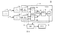
本発明の代替的な実施形態が図8に提供される。この実施形態では、2つの分離した電流ループ、すなわち、2つの受信アンテナ36a、36bと、2つの電圧制限器56a、56bと、2つの可変増幅器/フィルタ64a、64bと、を備える2つの個別経路であってもよい。各ループにおける電流の位相は、種々の異なる方向において最大範囲を達成するため、独立して、例えば、「同相で」、「位相から90度ずれて」、「位相から180度ずれて」制御され得る。金属検出モジュール38は、この特定のアンテナ構造を利用することができる。例えば、送信ペデスタルの2つのアンテナ32は同相で送信してもよい。もし2つの受信アンテナ36a、36bで誘導された電圧が、異なる増幅器66に供給される場合、バックグラウンドの送信の実効が最小化される。理想的な状況では、2つのコイルが完璧な位置に設置される場合、正味の差電圧はゼロにされ得る。実施において、正味の信号は、さらに信号を増幅/調整するのに十分な小さな信号だけが必要とされる。
An alternative embodiment of the present invention is provided in FIG. In this embodiment, two separate paths comprising two separate current loops: two receive
一方のペデスタルの送信器は58kHzのEM場の1.6ミリ秒のバーストを送信し、反対側のペデスタルにある2つのループ(受信アンテナ36a、36b)は電圧を誘導し、形状、巻き線の数が同一のため、電圧はほぼ等しい。信号は、ほぼゼロの正味電圧とともに差電圧増幅器66に供給される。金属が存在するとき、2つの受信経路の均衡が崩れ、それゆえ差電圧増幅器66の出力において微弱な信号が作り出される。この信号は金属が存在するかどうかを決定するため、次いで増幅器/フィルタ58を介して供給され、ADC58によりデジタル化され、そしてDSP62により処理される。
One pedestal transmitter transmits a 1.6 millisecond burst of the 58 kHz EM field, and the two loops (receive
先の実施形態のように、長期間のシステムドリフト、または短時間のシステム構造の乱れにより、差電圧増幅器66の出力において変化を生じさせることができる。この場合、警報器28は抑止されてもよく、均衡を達成するために各増幅器64a、64bの独立した可変利得を調整するように命令が送信されてもよい。
As in the previous embodiment, a change in the output of the
次に図9を参照すると、グラフが提供され、金属体が受信アンテナ36から移動する際に検出された信号の電圧を示している。信号の強さは、金属体の距離が長くなるとともに減少し、最小値に達し、対象が送信器に接近するにつれて再び増加する。
Referring now to FIG. 9, a graph is provided showing the voltage of the signal detected as the metal body moves from the receiving
図10は、受信のみのアンテナ(単数又は複数)36を使用し、検出のメカニズムを簡略にした代替的なシステム制御器16を示している。金属検出を目的として、別個の受信のみのアンテナ(単数又は複数)36が使用され得る。アンテナ36は、送信器に対し特定の位置および角度ゼロで設置された、空芯コイルループ、または(フェライト)コア付きアンテナにすることができる。この例では、このアンテナは、送信目的のために使用されないので、先の実施形態の電圧制限回路が除かれてもよい。さらに、的確な配向により、アンテナ36は、送信されたEM場による誘導を最小化するように位置付けられてもよい。バックグラウンドの高い誘導電圧無しに、金属の存在に起因して検出された小さな電圧は、より高い利得によって増幅され得、それゆえ、より優れた感度を提供する。
FIG. 10 shows an
加えて、本発明は、いくつかの著しい有利性を提供する磁石/磁性材料の検出を含んでもよい。一例では、磁石は、万引き犯によるEASマーカの磁性状態を変えるために使用され得る。別の例では、磁性特性を検出することで、検出された金属の種類がシステムにより識別されてもよい。例えば、通常のアルミ箔/金属は、一般的に磁性鋼でできたショッピングカートと容易に区別することができる。従って、磁場検出器17が、問い合わせ区域内で検出された金属が、例えばショッピングカートのように、さらに磁性でもあると判定する場合、システム制御器16は警報器28の始動を止める、または自制することができる。
In addition, the present invention may include magnet / magnetic material detection that offers several significant advantages. In one example, a magnet can be used to change the magnetic state of an EAS marker by a shoplifter. In another example, the detected metal type may be identified by the system by detecting magnetic properties. For example, a normal aluminum foil / metal can be easily distinguished from a shopping cart typically made of magnetic steel. Thus, if the
極端にいえば、拳銃のような銃器も磁性鋼でできている。それゆえ、本発明のEAS金属検出システム10は、万引きに対する機能に加え、最初のセキュリティーチェックを提供することも可能である。
Extremely speaking, firearms such as pistols are also made of magnetic steel. Therefore, the EAS
フラックスゲート磁力計、巨大磁気抵抗センサ、ガウスメーター、または任意の他の磁場感知デバイスのような、従来の高感度磁性センサが、このような磁性感知の目的のために使用されてもよい。磁力計センサは、磁石の存在による磁場の乱れを検出できる、非常に敏感なデバイスである。そのような機能の信頼性のある実行により、送信アンテナからの送信は無くすべきである。結果として、磁性の感知は、図4で示されるように、タグ検出窓44、同期窓46、およびノイズ窓48のうちの1つの時間枠の間に遂行されるべきである。
Conventional sensitive magnetic sensors, such as fluxgate magnetometers, giant magnetoresistive sensors, gauss meters, or any other magnetic field sensing device may be used for such magnetic sensing purposes. A magnetometer sensor is a very sensitive device that can detect magnetic field disturbances due to the presence of a magnet. With reliable execution of such a function, there should be no transmission from the transmit antenna. As a result, magnetic sensing should be performed during the time frame of one of the
本発明は、ハードウェア、ソフトウェア、またはハードウェアおよびソフトウェアの組み合わせで実現され得る。本明細書で説明された方法を実行するために適合された任意の種類のコンピュータシステムまたは他の装置が、本明細書で説明された機能を果たすように適合される。 The present invention can be realized in hardware, software, or a combination of hardware and software. Any type of computer system or other apparatus adapted to perform the methods described herein is adapted to perform the functions described herein.
ハードウェアおよびソフトウェアの典型的な組み合わせは、1つ以上の処理要素および記憶媒体に記憶されたコンピュータプログラムを有する特殊なコンピュータシステムであってもよく、当該コンピュータプログラムは、ロードされ実行されると、本明細書で説明された方法を実行するようにコンピュータシステムを制御する。本発明はまた、コンピュータプログラム製品に組み込まれてもよく、当該コンピュータプログラム製品は、本明細書で説明された方法の実施を可能にする全ての特徴を含み、コンピュータシステムにロードされた場合これらの方法を実行することができる。記憶媒体は、任意の揮発性または不揮発性の記憶デバイスを意味する。 A typical combination of hardware and software may be a special computer system having one or more processing elements and a computer program stored on a storage medium that, when loaded and executed, A computer system is controlled to perform the methods described herein. The present invention may also be incorporated into a computer program product, which includes all features that enable the implementation of the methods described herein and that when loaded into a computer system The method can be carried out. Storage medium means any volatile or non-volatile storage device.
本内容におけるコンピュータプログラムまたはアプリケーションは、情報処理能力を有するシステムに、直接か、あるいは、a)別の言語、コード若しくは表記への変換、又は、b)異なる材料形態に再生、の片方若しくは両方の後か、のいずれかに、特定の機能を遂行させることを目的とする一連の指示の、任意の言語、コードまたは表記における任意の表現を意味する。 A computer program or application in this content may be either directly or either on a system with information processing capabilities, or a) conversion to another language, code or notation, or b) playback to a different material form. Means any representation in any language, code or notation of a series of instructions intended to perform a specific function either later.
加えて、前述と相容れないことが記述されていない限り、すべての添付の図面は原寸に比例していないことに注意すべきである。意義深いことには、本発明は、その精神またはその本質的な特性から逸脱することなく別の特定の形態で具体化することができ、それ故に、言及は、本発明の範囲を示すものとして、前述の明細書ではなく以下の請求の範囲に対してなされるべきものである。 In addition, it should be noted that all accompanying drawings are not drawn to scale unless otherwise stated to the contrary. Significantly, the present invention may be embodied in other specific forms without departing from its spirit or its essential characteristics, and thus the references are intended to indicate the scope of the present invention. Instead of the foregoing specification, it is intended to be directed to the following claims.
Claims (17)
EAS問い合わせ信号を送信するステップであって、前記EAS問い合わせ信号は、問い合わせ区域を確立し、且つ前記問い合わせ区域内でEASマーカおよび金属体を検出するために使用されることを特徴とする、EAS問い合わせ信号を送信するステップと、
前記EAS信号を受信するステップと、
受信した前記EAS問い合わせ信号の摂動に基づいて、金属検出サイクルの間に前記問い合わせ区域における金属体の存在を検出するステップであって、前記金属検出サイクルが少なくとも1回のEAS検出サイクルに周期的に組み入れられることを特徴とする、金属体の存在を検出するステップと、
を含み、
前記金属体の存在を検出するステップは、
金属体が前記EASシステムに接近していないときの、受信したEAS問い合わせ信号を第1電圧と決定するステップと、
受信したEAS問い合わせ信号の電圧(第2電圧)を、前記第1電圧と比較するステップと、
を含み、前記第2電圧が前記第1電圧よりも低いという判断に応答して、前記金属体が存在すると判断することを特徴とする、
方法。 A method for detecting metal using electronic article surveillance ("EAS") comprising a transmitter and a receiver, comprising:
EAS and transmitting an inquiry signal, the EAS interrogation signal establishes an interrogation zone, and characterized in that it is used to detect EAS markers and metal objects in the query zone, EAS Contact Transmitting a signal; and
Receiving said EAS signal,
Based on the perturbation of said received EAS interrogation signal, comprising the steps of detecting the presence of the metal body in the interrogation zone during a metal detection cycle, the metal detection cycle is at least one EAS periodically to detect cycle characterized in that it is incorporated, and detecting the presence of the metal body,
Including
Detecting the presence of the metal body comprises:
Determining a received EAS inquiry signal as a first voltage when a metal object is not approaching the EAS system ;
Comparing the voltage (second voltage) of the received EAS inquiry signal with the first voltage;
And determining that the metal body is present in response to a determination that the second voltage is lower than the first voltage.
Method.
前記送信器が動作中であり、且つ前記受信器が動作中ではない送信窓と、
前記受信器が動作中であり、且つ前記送信器が動作中ではない受信窓と、
を含むことを特徴とする請求項3に記載の方法。 The at least one EAS detection cycle is :
A transmission window in which the transmitter is in operation and the receiver is not in operation; and
A receiving window in which the receiver is in operation and the transmitter is not in operation; and
4. The method of claim 3, comprising:
前記金属体が磁性であるという判断に応答して前記警報器を止めるステップと、をさらに含むことを特徴とする請求項6に記載の方法。7. The method of claim 6, further comprising turning off the alarm in response to determining that the metal body is magnetic.
EAS問い合わせ信号を送信するように動作可能な送信器であって、前記EAS問い合わせ信号は、問い合わせ区域を確立し、且つ前記問い合わせ区域内でEASマーカおよび金属体を検出するために使用されることを特徴とする、送信器と、A transmitter operable to transmit an EAS interrogation signal, wherein the EAS interrogation signal is used to establish an interrogation zone and to detect EAS markers and metal objects within the interrogation zone A transmitter, characterized by
前記EAS問い合わせ信号を受信するように動作可能な受信器と、A receiver operable to receive the EAS interrogation signal;
受信した前記EAS問い合わせ信号の摂動に基づいて、金属検出サイクルの間に、前記EASシステムに接近した金属体を検出するように動作可能な金属検出器であって、前記金属検出サイクルが、少なくとも1回のEAS検出サイクルとともに周期的に組み入れられることを特徴とする、金属検出器と、A metal detector operable to detect a metal object approaching the EAS system during a metal detection cycle based on a perturbation of the received EAS interrogation signal, the metal detection cycle comprising at least one A metal detector, characterized by being incorporated periodically with one EAS detection cycle;
を備え、With
前記金属検出器は、The metal detector is
金属体が前記EASシステムに接近していないときの、受信したEAS問い合わせ信号を第1電圧と決定し、When the metal body is not approaching the EAS system, the received EAS inquiry signal is determined as the first voltage;
前記受信したEAS問い合わせ信号の電圧(第2電圧)を、前記第1電圧と比較し、Comparing the voltage of the received EAS inquiry signal (second voltage) with the first voltage;
前記第2電圧が前記第1電圧よりも低いという判断に応答して、前記金属体が存在すると判断することにより前記金属体を検出することを特徴とする、In response to the determination that the second voltage is lower than the first voltage, the metal body is detected by determining that the metal body is present.
システム。system.
前記送信器が動作中であり、前記受信器が動作中ではない送信窓と、A transmission window in which the transmitter is in operation and the receiver is not in operation; and
前記受信器が動作中であり、前記送信器が動作中ではない受信窓と、A receiving window in which the receiver is in operation and the transmitter is not in operation; and
を含むことを特徴とする、請求項10に記載のシステム。The system according to claim 10, comprising:
9. The system of claim 8, responsive to a determination that the second voltage is lower than the first voltage by at least a predetermined threshold.
前記金属体が磁性であるという判断に応答して前記警報器を止める動作が可能な磁性材料検出器をさらに備えることを特徴とする、請求項13に記載のシステム。The system according to claim 13, further comprising a magnetic material detector capable of stopping the alarm in response to determining that the metal body is magnetic.
2つの受信アンテナと、Two receiving antennas,
2つの入力接続部および1つの出力接続部を有する差電圧増幅器であって、各入力接続部は前記受信アンテナの対応する一方に電気的に連結されることを特徴とする差電圧増幅器と、A differential voltage amplifier having two input connections and one output connection, wherein each input connection is electrically coupled to a corresponding one of the receiving antennas;
を備え、With
前記金属体は、前記出力接続部の電圧が所定の閾値を越えているとの判断により検出されることを特徴とする、請求項8に記載のシステム。The system according to claim 8, wherein the metal body is detected by determining that a voltage of the output connection exceeds a predetermined threshold value.
送信窓の間に電磁信号を生成するように動作可能な送信器であって、前記電磁信号が問い合わせ区域を確立し、且つ前記問い合わせ区域内の電子物品監視(「EAS」)マーカおよび金属体を検出するために使用されることを特徴とする送信器と、
検出窓の間にEASマーカから受信した信号を検出するように動作可能な受信器と、
前記送信窓の間に前記問い合わせ区域に接近した金属体を、前記金属体により作り出された前記電磁信号の摂動に基づいて検出するような動作が可能な金属検出器と、
を備え
前記金属検出器は、
金属体が前記問い合わせ区域に接近していないときの、受信した電磁信号を第1電圧と決定し、
受信した電磁信号の電圧(第2電圧)を、前記第1電圧と比較し、
前記第2電圧が前記第1電圧よりも低いという判断に応答して、前記金属体が存在すると判断することにより前記金属体を検出することを特徴とする、
システム。 A metal detection system,
A transmitter operable to generate an electromagnetic signal during a transmission window, wherein the electromagnetic signal establishes an interrogation zone, and an electronic article surveillance ("EAS") marker and metal body within the interrogation zone A transmitter characterized in that it is used to detect;
A receiver operable to detect a signal received from an EAS marker during a detection window;
A metal detector operable to detect a metal body approaching the interrogation zone during the transmission window based on perturbations of the electromagnetic signal produced by the metal body;
With
The metal detector is
Determining the received electromagnetic signal as the first voltage when the metal body is not approaching the inquiry area;
Comparing the voltage of the received electromagnetic signal (second voltage) with the first voltage ;
In response to the determination that the second voltage is lower than the first voltage, the metal body is detected by determining that the metal body is present.
system.
前記金属体が磁性であるかどうかを判断する動作が可能であり、かつ、前記金属体が磁性であるという判断に応答して、前記金属検出器は前記警報器を止める動作が可能である磁場検出器と、A magnetic field capable of determining whether the metal body is magnetic and in response to determining that the metal body is magnetic, the metal detector is capable of stopping the alarm. A detector;
を備える請求項16に記載のシステム。The system of claim 16.
Applications Claiming Priority (3)
| Application Number | Priority Date | Filing Date | Title |
|---|---|---|---|
| US13413708P | 2008-07-07 | 2008-07-07 | |
| US61/134,137 | 2008-07-07 | ||
| PCT/US2009/003842 WO2010005499A2 (en) | 2008-07-07 | 2009-06-27 | Electronic article surveillance system with metal detection capability and method therefor |
Publications (2)
| Publication Number | Publication Date |
|---|---|
| JP2011527481A JP2011527481A (en) | 2011-10-27 |
| JP5568718B2 true JP5568718B2 (en) | 2014-08-13 |
Family
ID=41395781
Family Applications (1)
| Application Number | Title | Priority Date | Filing Date |
|---|---|---|---|
| JP2011517405A Active JP5568718B2 (en) | 2008-07-07 | 2009-06-27 | Electronic article monitoring system with metal detection capability and method therefor |
Country Status (15)
| Country | Link |
|---|---|
| US (1) | US8704638B2 (en) |
| EP (1) | EP2297716B1 (en) |
| JP (1) | JP5568718B2 (en) |
| KR (1) | KR101596282B1 (en) |
| CN (1) | CN102089792B (en) |
| AR (1) | AR072704A1 (en) |
| AU (1) | AU2009269918B2 (en) |
| BR (1) | BRPI0913976A2 (en) |
| CA (1) | CA2729792C (en) |
| ES (1) | ES2459916T3 (en) |
| HK (1) | HK1154301A1 (en) |
| IL (1) | IL210044A0 (en) |
| MX (1) | MX2011000180A (en) |
| RU (1) | RU2533499C2 (en) |
| WO (1) | WO2010005499A2 (en) |
Families Citing this family (22)
| Publication number | Priority date | Publication date | Assignee | Title |
|---|---|---|---|---|
| BRPI0605714B1 (en) * | 2006-03-07 | 2018-06-26 | José Gouveia Abrunhosa Jorge | DEVICE AND PROCESS FOR DETECTION OF MAGNETIC MATERIALS IN ELECTROMAGNETIC TECHNOLOGY ANTI-THEFT SYSTEMS |
| WO2011044915A1 (en) * | 2009-10-16 | 2011-04-21 | Alert Metalguard Aps | An electronic anti-theft protection system |
| US8816854B2 (en) * | 2009-11-10 | 2014-08-26 | Tyco Fire & Security Gmbh | System and method for reducing cart alarms and increasing sensitivity in an EAS system with metal shielding detection |
| US8477032B2 (en) * | 2009-11-10 | 2013-07-02 | Tyco Fire & Security Gmbh | System and method using proximity detection for reducing cart alarms and increasing sensitivity in an EAS system with metal shielding detection |
| US8311485B2 (en) * | 2010-01-13 | 2012-11-13 | Sensormatic Electronics, LLC | Method and system for receiver nulling using coherent transmit signals |
| US8659428B2 (en) | 2010-03-03 | 2014-02-25 | Tyco Fire & Security Gmbh | Method and system for reducing effect of interference in integrated metal detection/electronic article surveillance systems |
| US20110260865A1 (en) * | 2010-04-26 | 2011-10-27 | Sensormatic Electronics, LLC | Method for reducing metal detection system false alarms |
| US8264353B2 (en) * | 2010-05-06 | 2012-09-11 | Sensormatic Electronics, LLC | Method and system for sliding door pattern cancellation in metal detection |
| AU2011295626B2 (en) * | 2010-08-29 | 2015-11-19 | Goldwing Design & Construction Pty Ltd | Method and apparatus for a metal detection system |
| US8576045B2 (en) * | 2010-10-15 | 2013-11-05 | Tyco Fire & Security Gmbh | Synchronization of electronic article surveillance systems having metal detection |
| NL2006927C2 (en) * | 2011-06-10 | 2012-12-11 | Cross Point B V | ELECTRONIC ARTICLE-MONITORING SYSTEM AND METHOD FOR DETECTING METAL THEREOF. |
| ES2714454T3 (en) * | 2012-01-19 | 2019-05-28 | Sensormatic Electronics Llc | Method and system for canceling an adaptive sliding door pattern in metal detection |
| FI127537B (en) * | 2012-04-11 | 2018-08-31 | Marisense Oy | Electronic label tag and electronic label tag system |
| DE102012211549B3 (en) | 2012-07-03 | 2013-07-04 | Polytec Gmbh | Apparatus and method for interferometric measurement of an object |
| US9245432B2 (en) * | 2013-08-15 | 2016-01-26 | Xiao Hui Yang | EAS tag utilizing magnetometer |
| KR102229022B1 (en) * | 2014-03-18 | 2021-03-17 | 삼성전자주식회사 | Device of detecting card having magnetic field monitor and System including the same |
| US10937289B2 (en) * | 2014-09-18 | 2021-03-02 | Indyme Solutions, Llc | Merchandise activity sensor system and methods of using same |
| HUE052495T2 (en) * | 2016-07-26 | 2021-04-28 | Alert Systems Aps | Theft prevention system and method |
| FR3067506B1 (en) * | 2017-06-08 | 2020-10-02 | Alain Dameme | MULTI-FUNCTIONAL CONTROL DEVICE. |
| JP6734831B2 (en) * | 2017-10-04 | 2020-08-05 | 矢崎総業株式会社 | Detection equipment and detection system |
| FR3083329B1 (en) * | 2018-06-28 | 2021-06-18 | Alessandro Manneschi | PORTABLE DETECTION SYSTEM INCLUDING MAGNETOSTATIC SENSORS |
| US11407381B2 (en) * | 2019-08-07 | 2022-08-09 | Keep Technologies, Inc. | Multi-device vehicle intrusion detection |
Family Cites Families (17)
| Publication number | Priority date | Publication date | Assignee | Title |
|---|---|---|---|---|
| US699046A (en) * | 1901-11-05 | 1902-04-29 | William A Shear | Jar closure and fastener. |
| US2337352A (en) * | 1942-08-24 | 1943-12-21 | Gen Electric | Metal detector |
| US4709213A (en) | 1982-07-23 | 1987-11-24 | Garrett Electronics, Inc. | Metal detector having digital signal processing |
| US4622543A (en) * | 1984-03-22 | 1986-11-11 | Anderson Iii Philip M | Surveillance system having acoustic magnetomechanical marker |
| US4821023A (en) * | 1988-01-07 | 1989-04-11 | Del Norte Technology, Inc. | Walk-through metal detector |
| US4791412A (en) * | 1988-01-28 | 1988-12-13 | Controlled Information Corporation | Magnetic article surveillance system and method |
| US5189397A (en) | 1992-01-09 | 1993-02-23 | Sensormatic Electronics Corporation | Method and apparatus for determining the magnitude of a field in the presence of an interfering field in an EAS system |
| GB9305085D0 (en) * | 1993-03-12 | 1993-04-28 | Esselte Meto Int Gmbh | Electronic article surveillance system with enhanced geometric arrangement |
| US5414411A (en) | 1993-06-21 | 1995-05-09 | White's Electronics, Inc. | Pulse induction metal detector |
| NL1000069C2 (en) * | 1995-04-07 | 1996-10-08 | Nedap Nv | Anti-theft system with integrated metal detector. |
| BR9604805A (en) * | 1995-04-07 | 1998-06-09 | Minnesota Mining & Mfg | Electronic surveillance system for articles and the process of detecting the presence of a sensitized tag in an interrogation hall |
| US5699046A (en) * | 1995-11-02 | 1997-12-16 | Sensormatic Electronics Corporation | EAS system employing central and local stations with shared functions |
| UA52804C2 (en) * | 1997-12-02 | 2003-01-15 | Текнікал Графікс Сек'Юріті Продактс, Ллс | Device for protecting documents by using magnetic and metallic protective elements (variants); method for producing the protection device (variants); method for identifying documents |
| JP3690368B2 (en) * | 2002-06-12 | 2005-08-31 | 大成建設株式会社 | Security management system |
| US7019650B2 (en) * | 2003-03-03 | 2006-03-28 | Caducys, L.L.C. | Interrogator and interrogation system employing the same |
| US7616092B2 (en) * | 2004-05-11 | 2009-11-10 | Sensormatic Electronics Corporation | Wireless transponder for a security system |
| US7701337B2 (en) | 2005-08-31 | 2010-04-20 | Allan Westersten | Hybrid-technology metal detector |
-
2009
- 2009-06-26 US US12/492,309 patent/US8704638B2/en active Active
- 2009-06-27 ES ES09752911.9T patent/ES2459916T3/en active Active
- 2009-06-27 CA CA2729792A patent/CA2729792C/en active Active
- 2009-06-27 RU RU2011104070/08A patent/RU2533499C2/en active
- 2009-06-27 EP EP09752911.9A patent/EP2297716B1/en active Active
- 2009-06-27 KR KR1020117002887A patent/KR101596282B1/en active IP Right Grant
- 2009-06-27 CN CN200980126259.8A patent/CN102089792B/en active Active
- 2009-06-27 JP JP2011517405A patent/JP5568718B2/en active Active
- 2009-06-27 WO PCT/US2009/003842 patent/WO2010005499A2/en active Application Filing
- 2009-06-27 MX MX2011000180A patent/MX2011000180A/en active IP Right Grant
- 2009-06-27 BR BRPI0913976A patent/BRPI0913976A2/en not_active Application Discontinuation
- 2009-06-27 AU AU2009269918A patent/AU2009269918B2/en active Active
- 2009-07-07 AR ARP090102553A patent/AR072704A1/en not_active Application Discontinuation
-
2010
- 2010-12-16 IL IL210044A patent/IL210044A0/en unknown
-
2011
- 2011-08-02 HK HK11107974.2A patent/HK1154301A1/en unknown
Also Published As
| Publication number | Publication date |
|---|---|
| CA2729792C (en) | 2017-07-11 |
| EP2297716A2 (en) | 2011-03-23 |
| CA2729792A1 (en) | 2010-01-14 |
| CN102089792A (en) | 2011-06-08 |
| AU2009269918B2 (en) | 2015-02-05 |
| RU2011104070A (en) | 2012-08-20 |
| WO2010005499A3 (en) | 2010-03-04 |
| AU2009269918A1 (en) | 2010-01-14 |
| WO2010005499A2 (en) | 2010-01-14 |
| KR20110043651A (en) | 2011-04-27 |
| RU2533499C2 (en) | 2014-11-20 |
| BRPI0913976A2 (en) | 2015-10-27 |
| IL210044A0 (en) | 2011-02-28 |
| JP2011527481A (en) | 2011-10-27 |
| AR072704A1 (en) | 2010-09-15 |
| US8704638B2 (en) | 2014-04-22 |
| KR101596282B1 (en) | 2016-02-22 |
| EP2297716B1 (en) | 2014-04-02 |
| ES2459916T3 (en) | 2014-05-12 |
| MX2011000180A (en) | 2011-03-24 |
| HK1154301A1 (en) | 2012-04-13 |
| CN102089792B (en) | 2015-05-20 |
| US20100001872A1 (en) | 2010-01-07 |
Similar Documents
| Publication | Publication Date | Title |
|---|---|---|
| JP5568718B2 (en) | Electronic article monitoring system with metal detection capability and method therefor | |
| EP2543025B1 (en) | Method and system for reducing effect of interference in integrated metal detection/electronic article surveillance systems | |
| EP2564244B1 (en) | Method for reducing metal detection system false alarms | |
| RU2268496C2 (en) | Electronic device for preventing thefts | |
| AU2011249046A1 (en) | Method for reducing metal detection system false alarms | |
| WO2011139323A2 (en) | Method and system for sliding door pattern cancellation in metal detection | |
| EP1991968B1 (en) | Device and process for magnetic material detection in electronic article surveillance (eas) electromagnetic systems | |
| JPH0850690A (en) | Burglarproof system | |
| AU2015252034B2 (en) | Method and system for reducing effect of interference in integrated metal detection/electronic article surveillance systems |
Legal Events
| Date | Code | Title | Description |
|---|---|---|---|
| A621 | Written request for application examination |
Free format text: JAPANESE INTERMEDIATE CODE: A621 Effective date: 20120402 |
|
| A131 | Notification of reasons for refusal |
Free format text: JAPANESE INTERMEDIATE CODE: A131 Effective date: 20130205 |
|
| A977 | Report on retrieval |
Free format text: JAPANESE INTERMEDIATE CODE: A971007 Effective date: 20130206 |
|
| A601 | Written request for extension of time |
Free format text: JAPANESE INTERMEDIATE CODE: A601 Effective date: 20130426 |
|
| A602 | Written permission of extension of time |
Free format text: JAPANESE INTERMEDIATE CODE: A602 Effective date: 20130508 |
|
| A601 | Written request for extension of time |
Free format text: JAPANESE INTERMEDIATE CODE: A601 Effective date: 20130604 |
|
| A602 | Written permission of extension of time |
Free format text: JAPANESE INTERMEDIATE CODE: A602 Effective date: 20130611 |
|
| A601 | Written request for extension of time |
Free format text: JAPANESE INTERMEDIATE CODE: A601 Effective date: 20130703 |
|
| A602 | Written permission of extension of time |
Free format text: JAPANESE INTERMEDIATE CODE: A602 Effective date: 20130724 |
|
| A521 | Request for written amendment filed |
Free format text: JAPANESE INTERMEDIATE CODE: A523 Effective date: 20130805 |
|
| A521 | Request for written amendment filed |
Free format text: JAPANESE INTERMEDIATE CODE: A523 Effective date: 20140204 |
|
| TRDD | Decision of grant or rejection written | ||
| A01 | Written decision to grant a patent or to grant a registration (utility model) |
Free format text: JAPANESE INTERMEDIATE CODE: A01 Effective date: 20140325 |
|
| A711 | Notification of change in applicant |
Free format text: JAPANESE INTERMEDIATE CODE: A711 Effective date: 20140421 |
|
| A61 | First payment of annual fees (during grant procedure) |
Free format text: JAPANESE INTERMEDIATE CODE: A61 Effective date: 20140423 |
|
| R150 | Certificate of patent or registration of utility model |
Ref document number: 5568718 Country of ref document: JP Free format text: JAPANESE INTERMEDIATE CODE: R150 |
|
| R250 | Receipt of annual fees |
Free format text: JAPANESE INTERMEDIATE CODE: R250 |
|
| R250 | Receipt of annual fees |
Free format text: JAPANESE INTERMEDIATE CODE: R250 |
|
| R250 | Receipt of annual fees |
Free format text: JAPANESE INTERMEDIATE CODE: R250 |
|
| R250 | Receipt of annual fees |
Free format text: JAPANESE INTERMEDIATE CODE: R250 |
|
| R250 | Receipt of annual fees |
Free format text: JAPANESE INTERMEDIATE CODE: R250 |
|
| R250 | Receipt of annual fees |
Free format text: JAPANESE INTERMEDIATE CODE: R250 |
|
| R250 | Receipt of annual fees |
Free format text: JAPANESE INTERMEDIATE CODE: R250 |