JP5568061B2 - CO2 sensor and CO2 measuring device - Google Patents
CO2 sensor and CO2 measuring device Download PDFInfo
- Publication number
- JP5568061B2 JP5568061B2 JP2011141059A JP2011141059A JP5568061B2 JP 5568061 B2 JP5568061 B2 JP 5568061B2 JP 2011141059 A JP2011141059 A JP 2011141059A JP 2011141059 A JP2011141059 A JP 2011141059A JP 5568061 B2 JP5568061 B2 JP 5568061B2
- Authority
- JP
- Japan
- Prior art keywords
- sensing unit
- unit
- sensor
- sensing
- attachment member
- Prior art date
- Legal status (The legal status is an assumption and is not a legal conclusion. Google has not performed a legal analysis and makes no representation as to the accuracy of the status listed.)
- Active
Links
- 239000000853 adhesive Substances 0.000 claims description 24
- 230000001070 adhesive effect Effects 0.000 claims description 24
- 238000005259 measurement Methods 0.000 claims description 19
- 230000003287 optical effect Effects 0.000 claims description 14
- 239000013307 optical fiber Substances 0.000 claims description 8
- 239000000126 substance Substances 0.000 claims description 5
- 239000004744 fabric Substances 0.000 claims description 4
- 238000010586 diagram Methods 0.000 description 18
- 230000004048 modification Effects 0.000 description 11
- 238000012986 modification Methods 0.000 description 11
- 230000000241 respiratory effect Effects 0.000 description 7
- 230000029058 respiratory gaseous exchange Effects 0.000 description 7
- QVGXLLKOCUKJST-UHFFFAOYSA-N atomic oxygen Chemical compound [O] QVGXLLKOCUKJST-UHFFFAOYSA-N 0.000 description 6
- 229910052760 oxygen Inorganic materials 0.000 description 6
- 239000001301 oxygen Substances 0.000 description 6
- 230000010352 nasal breathing Effects 0.000 description 3
- 238000002627 tracheal intubation Methods 0.000 description 3
- 239000000975 dye Substances 0.000 description 2
- 230000031700 light absorption Effects 0.000 description 2
- 239000011347 resin Substances 0.000 description 2
- 229920005989 resin Polymers 0.000 description 2
- 238000004566 IR spectroscopy Methods 0.000 description 1
- 208000001705 Mouth breathing Diseases 0.000 description 1
- 238000010521 absorption reaction Methods 0.000 description 1
- 238000002680 cardiopulmonary resuscitation Methods 0.000 description 1
- 238000001514 detection method Methods 0.000 description 1
- 230000000694 effects Effects 0.000 description 1
- 239000003792 electrolyte Substances 0.000 description 1
- 208000015181 infectious disease Diseases 0.000 description 1
- 239000000463 material Substances 0.000 description 1
- 238000000034 method Methods 0.000 description 1
- 239000004745 nonwoven fabric Substances 0.000 description 1
- 239000002759 woven fabric Substances 0.000 description 1
Images


Classifications
-
- A—HUMAN NECESSITIES
- A61—MEDICAL OR VETERINARY SCIENCE; HYGIENE
- A61B—DIAGNOSIS; SURGERY; IDENTIFICATION
- A61B5/00—Measuring for diagnostic purposes; Identification of persons
- A61B5/08—Detecting, measuring or recording devices for evaluating the respiratory organs
- A61B5/082—Evaluation by breath analysis, e.g. determination of the chemical composition of exhaled breath
-
- A—HUMAN NECESSITIES
- A61—MEDICAL OR VETERINARY SCIENCE; HYGIENE
- A61B—DIAGNOSIS; SURGERY; IDENTIFICATION
- A61B5/00—Measuring for diagnostic purposes; Identification of persons
- A61B5/0059—Measuring for diagnostic purposes; Identification of persons using light, e.g. diagnosis by transillumination, diascopy, fluorescence
- A61B5/0075—Measuring for diagnostic purposes; Identification of persons using light, e.g. diagnosis by transillumination, diascopy, fluorescence by spectroscopy, i.e. measuring spectra, e.g. Raman spectroscopy, infrared absorption spectroscopy
-
- A—HUMAN NECESSITIES
- A61—MEDICAL OR VETERINARY SCIENCE; HYGIENE
- A61B—DIAGNOSIS; SURGERY; IDENTIFICATION
- A61B5/00—Measuring for diagnostic purposes; Identification of persons
- A61B5/08—Detecting, measuring or recording devices for evaluating the respiratory organs
- A61B5/083—Measuring rate of metabolism by using breath test, e.g. measuring rate of oxygen consumption
- A61B5/0836—Measuring rate of CO2 production
-
- A—HUMAN NECESSITIES
- A61—MEDICAL OR VETERINARY SCIENCE; HYGIENE
- A61B—DIAGNOSIS; SURGERY; IDENTIFICATION
- A61B5/00—Measuring for diagnostic purposes; Identification of persons
- A61B5/68—Arrangements of detecting, measuring or recording means, e.g. sensors, in relation to patient
- A61B5/6801—Arrangements of detecting, measuring or recording means, e.g. sensors, in relation to patient specially adapted to be attached to or worn on the body surface
- A61B5/6802—Sensor mounted on worn items
- A61B5/6803—Head-worn items, e.g. helmets, masks, headphones or goggles
-
- A—HUMAN NECESSITIES
- A61—MEDICAL OR VETERINARY SCIENCE; HYGIENE
- A61B—DIAGNOSIS; SURGERY; IDENTIFICATION
- A61B5/00—Measuring for diagnostic purposes; Identification of persons
- A61B5/68—Arrangements of detecting, measuring or recording means, e.g. sensors, in relation to patient
- A61B5/6801—Arrangements of detecting, measuring or recording means, e.g. sensors, in relation to patient specially adapted to be attached to or worn on the body surface
- A61B5/6813—Specially adapted to be attached to a specific body part
- A61B5/6814—Head
Landscapes
- Health & Medical Sciences (AREA)
- Life Sciences & Earth Sciences (AREA)
- Physics & Mathematics (AREA)
- Medical Informatics (AREA)
- Surgery (AREA)
- Biophysics (AREA)
- Pathology (AREA)
- Engineering & Computer Science (AREA)
- Biomedical Technology (AREA)
- Heart & Thoracic Surgery (AREA)
- Veterinary Medicine (AREA)
- Molecular Biology (AREA)
- Public Health (AREA)
- Animal Behavior & Ethology (AREA)
- General Health & Medical Sciences (AREA)
- Pulmonology (AREA)
- Physiology (AREA)
- Emergency Medicine (AREA)
- Obesity (AREA)
- Spectroscopy & Molecular Physics (AREA)
- Measurement Of The Respiration, Hearing Ability, Form, And Blood Characteristics Of Living Organisms (AREA)
- Investigating Or Analysing Biological Materials (AREA)
Description
この発明は、呼吸の有無や呼気CO2分圧を測定するためのCO2センサ及び、そのCO2センサを用いて構成したCO2測定装置に関するものである。 The present invention relates to a CO2 sensor for measuring presence / absence of breathing and partial pressure of exhaled CO2, and a CO2 measuring apparatus configured using the CO2 sensor.
呼気CO2分圧を測定するためのCO2センサには、CO2の赤外線吸収を利用した赤外線分光法によるもの(特許文献1参照)や、CO2による電解液のpH変化を色素の色変化として検出する色素法によるもの(特許文献2、3参照)などが知られている。 Examples of the CO2 sensor for measuring the partial pressure of exhaled CO2 include those based on infrared spectroscopy using infrared absorption of CO2 (see Patent Document 1), and dyes that detect pH changes in the electrolyte due to CO2 as color changes of the dyes. A method based on the law (see Patent Documents 2 and 3) is known.
上記特許文献1に記載されている赤外線方式のセンサは、非挿管で測定できるものの、高価であり、小型化・低消費電力化には限界がある。また、上記特許文献2、3に記載されている色素式のセンサは、安価であり、小型化・低消費電力化が可能であるという長所があるものの、挿管チューブに接続されたパイプの内部に配置して使用するタイプのものであり、非挿管で測定することができず、適用範囲が限定されるものであった。
Although the infrared sensor described in
本発明は、上記のようなCO2センサの現状に鑑みてなされたもので、その目的は、安価で小型で、低消費電力で、呼吸の有無や呼気CO2分圧の測定を行うことが可能であり、患者の呼吸管理に広く応用ができ、患者の安全に大きく寄与することが可能なCO2センサ及びCO2測定装置を提供することである。 The present invention has been made in view of the current situation of the CO2 sensor as described above, and its purpose is to be able to measure the presence or absence of breathing and exhaled CO2 partial pressure with low cost, small size, and low power consumption. It is to provide a CO2 sensor and a CO2 measuring device that can be widely applied to patient respiratory management and can greatly contribute to patient safety.
本発明に係るCO2センサは、生体の鼻孔及び/または口からの呼気のCO2分圧に応じて色変化するセンシング部と、このセンシング部を、前記鼻孔からの呼気が直接当たるように前記鼻孔の近傍に着脱可能に配置保持するために、前記センシング部を保持し、前記生体に支持され得る、テープあるいはシートからなる取付部材と、を具備し、前記センシング部は、CO2分圧に応じて色変化する薬液を担体としての布あるいは紙に担持させて、または前記取付部材に担持させて構成されている、ことを特徴とする。 The CO2 sensor according to the present invention includes a sensing unit that changes color according to the partial pressure of CO2 in exhaled air from the nostril and / or mouth of the living body, and the sensing unit is configured so that the exhaled air from the nostril directly contacts the sensing unit . An attachment member made of a tape or a sheet that holds the sensing unit and can be supported by the living body in order to be detachably disposed in the vicinity, and the sensing unit is colored according to the CO2 partial pressure. It is characterized in that the changing chemical solution is carried on a cloth or paper as a carrier, or carried on the mounting member .
本発明に係るCO2センサでは、前記取付部材は、前記センシング部を前記生体の人中上に配置保持することができることを特徴とする。 In the CO2 sensor according to the present invention, the attachment member is capable of arranging and holding the sensing unit on the living body.
本発明に係るCO2センサでは、前記取付部材は、人中上を中心として上唇の上側を長手方向に帯状に延びる粘着部と、前記粘着部に一体で、下方に延在するように形成され、前記生体側に上下方向に気流路が形成され、当該気流路の上端部に前記センシング部へ臨む開口部が設けられた口部カバーとで構成されていることを特徴とする。 In the CO2 sensor according to the present invention, the attachment member is formed so as to extend downward in an integrated manner with the adhesive portion extending in a band shape in the longitudinal direction on the upper side of the upper lip centering on the inside of the human body, An air flow path is formed in the up-down direction on the living body side, and the mouth cover is provided with an opening facing the sensing unit at an upper end portion of the air flow path .
本発明に係るCO2センサでは、前記取付部材は、さらに、前記粘着部と前記口部カバーとの結合部から前方へ突出し、透孔が穿設された突片を有し、この突片に前記透孔を塞ぐように前記センシング部と同様なセンシング部が設けられていることを特徴とする。 In the CO2 sensor according to the present invention, the mounting member further includes a projecting piece protruding forward from a joint portion between the adhesive portion and the mouth cover, and having a through-hole formed therein. A sensing part similar to the sensing part is provided so as to close the through hole .
本発明に係るCO2センサでは、前記取付部材は、人中上を中心として上唇の上側を長手方向に帯状に延びる粘着部と、前記粘着部に一体で、下方に延在するように形成され、前記生体側に上下方向に気流路が形成され、当該気流路の上端部に前記鼻孔の近傍へ臨む開口部が設けられた口部カバーと、前記粘着部と前記口部カバーとの結合部から前方へ突出し、透孔が穿設された突片とを有し、この突片に前記透孔を塞ぐように前記センシング部が設けられていることを特徴とする。 In the CO2 sensor according to the present invention, the attachment member is formed so as to extend downward in an integrated manner with the adhesive portion extending in a band shape in the longitudinal direction on the upper side of the upper lip centering on the inside of the human body, An air flow path is formed in the up-down direction on the living body side, an mouth cover provided with an opening facing the vicinity of the nostril at an upper end portion of the air flow path, and a joint portion between the adhesive portion and the mouth cover A projecting piece projecting forward and having a through hole, and the sensing section is provided on the projecting piece so as to close the through hole .
本発明に係るCO2センサでは、前記取付部材は、前記生体の顔面に保持され得るマスク状の通気性シートであることを特徴とする。
In the CO2 sensor according to the present invention, the attachment member is a mask-like breathable sheet that can be held on the face of the living body .
本発明に係るCO2測定装置は、請求項1乃至6のいずれかに記載のCO2センサを用いたCO2測定装置であって、光信号をセンシング部へ向けて出射する光源部と、前記センシング部からの光信号を取り込む受光部と、受光した光信号に基づいてCO2測定を行うCO2測定部と、を具備することを特徴とする。
A CO2 measuring apparatus according to the present invention is a CO2 measuring apparatus using the CO2 sensor according to any one of
本発明に係るCO2測定装置では、前記受光部は、前記センシング部において反射または透過された光信号を受光することを特徴とする。 In the CO2 measuring apparatus according to the present invention, the light receiving unit receives an optical signal reflected or transmitted by the sensing unit.
本発明に係るCO2測定装置では前記光源部は、波長の異なる少なくとも2種類の光信号を出射することを特徴とする。 In the CO2 measuring apparatus according to the present invention, the light source unit emits at least two types of optical signals having different wavelengths.
本発明に係るCO2測定装置は、前記光源部から前記センシング部及び前記センシング部から前記受光部の少なくとも一方に光を伝導するための光ファイバを設けたことを特徴とする。 The CO2 measuring device according to the present invention is characterized in that an optical fiber for conducting light is provided from at least one of the light source unit to the sensing unit and from the sensing unit to the light receiving unit.
本発明に係るCO2センサ及びCO2測定装置によれば、生体の鼻孔及び/または口からの呼気のCO2分圧に応じて色変化するセンシング部と、このセンシング部を、前記鼻孔及び/または口からの呼気が直接当たる位置に着脱可能に配置保持するために前記生体に支持される取付部材とを具備する構成であるから、コンパクトであり、電力消費を低く抑制することができ、簡易にCO2測定を行うことができる。 According to the CO2 sensor and the CO2 measurement device of the present invention, a sensing unit that changes color according to the CO2 partial pressure of exhaled air from the nostril and / or mouth of the living body, and the sensing unit are connected to the nostril and / or mouth. Since it has a configuration including an attachment member supported by the living body so as to be detachably disposed at a position where the exhaled breath directly hits, it is compact, can reduce power consumption, and can easily measure CO2. It can be performed.
本発明に係るCO2測定装置によれば、請求項1乃至6のいずれかに記載のCO2センサを用い、光信号をセンシング部へ向けて出射する光源部と、前記センシング部からの光信号を取り込む受光部と、受光した光信号に基づいてCO2測定を行うCO2測定部とを具備するので、受光した光信号を用いて高精度な測定を行うことも可能であり、患者の呼吸管理に広く応用ができ、患者の安全に大きく寄与することが可能である。
According to the CO2 measuring device of the present invention, the CO2 sensor according to any one of
以下添付図面を参照して、本発明に係るCO2センサ及びCO2測定装置の実施形態を説明する。各図において同一の構成要素には、同一の符号を付して重複する説明を省略する。図1には、本発明に係るCO2センサの第1の実施形態が示されている。このCO2センサ10は、ガーゼ付絆創膏の絆創膏(テープ)部分と概ね同一構成の長尺状の形状を有するテープやシートから構成されている取付部材11を有する。取付部材11が生体Aに貼着される第1の面12には、粘着剤が塗布されている。
Embodiments of a CO2 sensor and a CO2 measuring apparatus according to the present invention will be described below with reference to the accompanying drawings. In the drawings, the same components are denoted by the same reference numerals and redundant description is omitted. FIG. 1 shows a first embodiment of a CO2 sensor according to the present invention. The
取付部材11の第1の面12の裏面である第2の面13における中央部には、センシング部14が設けられている。センシング部14は、呼気CO2分圧に応じて色変化するもので、例えば、先に示した特許文献2、3に記載の薬液などを、担体としての布や紙などに担持させ、それを取付部材11に接着することで構成することができる。また、取付部材11に上記薬液を担持させるようにしてもよい。センシング部14の大きさは、人中上に丁度収まる程度とすることができる。センシング部14は、取付部材11によって着脱自在に鼻孔の近傍に設けられる。
A
以上の通り、第1の実施形態のCO2センサ10が、人中上に配置保持されることにより、鼻孔から排出された呼気のCO2がセンシング部14へ到り、CO2分圧に応じてセンシング部14が色変化する。従って、センシング部14の色変化を目視することによって、呼吸の有無及び呼気中に含まれるCO2の濃度を概略測定することができる。この構成のCO2センサ10は、鼻呼吸のみによって呼吸を行う新生児などに対する呼吸管理に好適である。
As described above, the
第2の実施形態に係るCO2センサ10Aの構成を図2、図3に示す。CO2センサ10Aの取付部材11Aは、人中上を中心として上唇の上側において、長手方向に帯状に延びる粘着部15と、この粘着部15に一体に、平面形状が例えば長方形形状や楕円形状で下方に延在するように形成された口部カバー16とを有する。
The configuration of the
粘着部15は薄手な絆創膏状の樹脂によって形成され、生体Aに貼着される第1の面12には、粘着剤が塗布されている。第1の面12の裏面である第2の面13における中央部には、センシング部14が貼着されている。
The
口部カバー16は、粘着部15よりも厚手の樹脂によって形成することができ、粘着部15から概ね直角に口方向へ垂下した状態に設けられている。口部カバー16は、反生体側に向かって中央部16Cが突出して上下方向に延び、中央部16Cの両側縁16S、16Sが口に近付くように傾斜して構成されている。
The mouth cover 16 can be formed of a resin that is thicker than the
口部カバー16の生体側には、上下方向に溝である気流路17が形成され、気流路17の上端部には、センシング部14へ臨む開口部18が穿設されている。以上の構成によって、気流路17が口から排出された呼気をセンシング部14へ導く機能を有する。
An
以上の通り、第2の実施形態のCO2センサ10Aが、人中上に配置保持されることにより、鼻孔と口から排出された呼気のCO2がセンシング部14へ到り、センシング部14が色変化する。従って、センシング部14の色変化を目視することによって、呼吸の有無及び呼気中に含まれるCO2の濃度を概略測定することができる。この構成のCO2センサ10Aは、鼻呼吸と口呼吸によって呼吸を行う成人などに対する呼吸管理に好適であるが、鼻呼吸のみを行う新生児にも適用可能である。
As described above, when the
図4は、第2の実施形態の変形例を示す。このCO2センサ10Bは、取付部材11Bの粘着部15における、少なくともセンシング部14の部分の断面が図4(b)に示すように、唇側において厚く、鼻側へ向かうほど肉薄に形成されている点において第2の実施形態と相違する。粘着部15の全体が、上記の通りに構成されていてもよい。このような構成を有するCO2センサ10Bによれば、センシング部14が図2、3の実施形態に比べて上側を向いた状態において生体Aに装着されるので、鼻孔から排出される呼気がセンシング部14に当たりやすくなり、鼻孔からのCO2検出の精度を向上させることができる。
FIG. 4 shows a modification of the second embodiment. The CO2 sensor 10B is formed such that at least the section of the
図5に、第3の実施形態を示す。このCO2センサ10Cは、取付部材11Cが第2の実施形態と基本的に同様の構成を有している。ここでは、粘着部15の一部分から前方へ突出した突片19を有する。具体的には、突片19は、粘着部15と口部カバー16との結合部から前方へ突出しており、開口部18の上部へ位置するように形成される。突片19には、開口部18と同程度の径を有する透孔19Aが穿設されている。透孔19Aの上部には、透孔19Aを塞ぐように、センシング部14と同じ構成のセンシング部14Aが載置して設けられている。口から排出された呼気中のCO2は気流路17から開口部18及び透孔19Aを介してセンシング部14Aへ到り、センシング部14Aの色変化をもたらす。また、鼻孔から排出された呼気中のCO2は、突片19に載置されているセンシング部14A及び粘着部15に設けられたセンシング部14へ到り、これらセンシング部14、14Aの色変化をもたらす。この実施形態により、二か所のセンシング部14、14Aにおいて、適切にCO2測定を行うことができる。
FIG. 5 shows a third embodiment. In this CO2 sensor 10C, the attachment member 11C has basically the same configuration as that of the second embodiment. Here, it has a protruding
図6には、図5における第3の実施形態の変形例が示されている。このCO2センサ10Dは、図5における第3の実施形態のCO2センサ10Cに備えられているセンシング部14を取り去ったもので、他の構成はCO2センサ10Cと同様である。この変形例においては、鼻孔及び口から排出された呼気中のCO2は、突片19に載置されているセンシング部14Aへ到り、これらセンシング部14Aの色変化をもたらす。
FIG. 6 shows a modification of the third embodiment in FIG. This
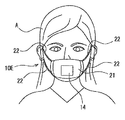
図7には、第4の実施形態に係るCO2センサ10Eが示されている。このCO2センサ10Eは、織布や不織布などの通気性シートで構成された取付部としてのマスク部21と、既に説明したセンシング部14とを有する。マスク部21は、平面形状が概ね長方形であり、装着したときに両頬に位置する2辺からは、耳に掛けてマスク部21を保持する紐22が延びている。この紐22によってマスク部21を装着したときに、センシング部14が口と鼻の前に位置するように、紐22の長さを調整することができる。マスク部21を構成する通気性シートの空気抵抗は、4mmH2O/cm2未満とする。
FIG. 7 shows a
この実施形態によれば、CO2センサ10Eを生体(患者)Aに装着させた状態において、心肺蘇生術を施すことができ、生体(患者)Aが呼吸を再開させたことなどを、センシング部14の色変化を観察することにより実現でき便利である。更に、マスク部21の上から非接触でマウスツーマウスによる人工呼吸を施すことができ、感染を防止することが可能である。
According to this embodiment, the cardiopulmonary resuscitation can be performed in a state where the
図8には、第5の実施形態に係るCO2センサ10Fが示されている。このCO2センサ10Fは、例えば透明のカップ形状やお椀形状の酸素マスク30の内壁部に、取付部材31を備える。取付部材31は、人中を左右両側から挟むように突出して対向する支持棒体32、32により構成される。センシング部33は、図8(b)に示すように二枚の長方形板が互いに直角に繋げられた形状を有し、その構成は既に説明したセンシング部14と同様に、呼気CO2分圧に応じて色変化するものであり、薬液などを、担体としての布や紙などに担持させたもので構成することができる。酸素マスク30は、図示しない紐やバンドによって口と鼻とを内包する状態で取り付けられ、酸素ボンベなどから図示しないチューブを介して酸素が送られる。
FIG. 8 shows a
センシング部33は、鼻孔呼気対応の第1のセンシング部34と、第1のセンシング部34の中央側辺から直角に延びる口呼気対応の第2のセンシング部35とにより構成されている。支持棒体32、32の対向面には、第1のセンシング部34の両端部34A、34Aが嵌合される穴あるいは溝により構成される把持部32A、32Aが形成されている。第1のセンシング部34の両端部34A、34Aが把持部32A、32Aに嵌合されて用いられ、必要に応じて未使用のものに取り換えて使用することが可能である。以上の構成を有しているため、酸素マスク30を装着した状態の生体(患者)Aの呼吸状態を、センシング部33の色変化によって観察し、必要な呼吸管理を行うことができる。
The
図9には、第6の実施形態に係るCO2センサ10Gが示されている。このCO2センサ10Gは、鼻カニューレ36に取付部材37を有している。センシング部38は、一枚の長方形形状を有し、その構成は既に説明したセンシング部14と同様に、呼気CO2分圧に応じて色変化するものであり、薬液などを、担体としての布や紙などに担持させたもので構成することができる。
FIG. 9 shows a
取付部材37は、センシング部38の上端縁部を弾性などで把持する機構によって構成することができる。また、取付部材37を鼻カニューレ36の筒体における外壁部として、この外壁部に対向するセンシング部38の上端縁部に粘着剤を塗布し、上記外壁部に貼着して構成してもよい。いずれの構成においても、センシング部38が鼻カニューレ36における筒体の最下面から吊り下げられた状態で、生体Aの口の前方に位置することになる。このセンシング部38に対し、口から排出された呼気のCO2が吹き掛けられ色変化を生じることになる。これにより、鼻カニューレ36が装着された患者の呼吸状態をセンシング部38の色変化によって監視することができ、当該患者に対する呼吸管理を容易に適切に行うことが可能である。このセンシング部38も、必要に応じて未使用のものに取り換えて使用することが可能である。
The
図10には、図6に示したセンサとほぼ同じCO2センサ10Hを用いて構成したCO2測定装置の第1の実施形態が示されている。突片19に形成されている透孔19Aに、センシング部14Bが着脱可能に嵌合されて設けられている。センシング部14Bは、センシング部14と同様の構成を有し、かつ透光性を有する。取付部材11Dにおける粘着部15の中央部には、LEDなどの発光素子によって構成される光源部41が取り付けられている。光源部41は、センシング部14Bの色変化による光吸収特性が影響を受け難い少なくとも1つの波長の光(第1の波長光)と、センシング部14Bの色変化による光吸収特性が影響を受け易い少なくとも1つの波長の光(第2の波長光)とを出射する。
FIG. 10 shows a first embodiment of a CO2 measuring apparatus configured using a
口部カバー16における開口部18を臨む先端部には、フォトセンサなどにより構成される受光部42が設けられている。受光部42は、センシング部14Bを介して光源部41と対向する位置に設けられており、光源部41から出射された光はセンシング部14Bを介して受光部42にて受光される。
A
光源部41及び受光部42は、CO2測定部50の入出力部51に接続されている。CO2測定部50の入出力部51には測定本体部52が接続され、測定本体部52には報知部53が接続されている。報知部53は、例えばLCDにより構成される表示装置を用いることができる。測定本体部52は、入出力部51を制御して光源部41から光を出射させる。受光部42は、センシング部14Bを介して光を受光して光電変換した信号を入出力部51へ送る。入出力部51には、第1の波長光に対応する受光信号と第2の波長光に対応する受光信号とが到来する。入出力部51は、これらの信号をディジタル化して測定本体部52へ送る。測定本体部52は、第1の波長光に対応するディジタル信号と第2の波長光に対応するディジタル信号との比較を行い、例えば、その比をCO2量(ppm)に変化するためにあらかじめ備えられているテーブルを用いてCO2量を求めて報知部53へ送る。これにより、簡単にセンサを配置することができると共に、適切にCO2量の測定を行うことが可能である。
The
図11には、図1に示したセンサとほぼ同じCO2センサ10Iを用いて構成したCO2測定装置の第2の実施形態が示されている。テープやシートから構成されている取付部材11に設けられた穴部に、センシング部14が着脱可能に埋設されて設けられている。鼻孔からの呼気が当たる第2の面13におけるセンシング部14に臨む位置には、光源部41と受光部42が設けられている。光源部41から出射された光は、センシング部14において反射し受光部42に受光されるように、光源部41と受光部42が配置されている。
FIG. 11 shows a second embodiment of a CO2 measuring apparatus configured using a CO2 sensor 10I that is substantially the same as the sensor shown in FIG. A
光源部41と受光部42がCO2測定部50の入出力部51に接続されている。測定部50の構成及び動作は、CO2測定装置の第2の実施形態と同様である。このため、CO2センサ10Iを人中上に貼着して、適切にCO2量の測定を行うことが可能である。
The
図12には、CO2測定装置の第2の実施形態の変形例が示されている。この変形例では、受光部42が第1の面12に設けられ、光源部41は第2の面13に設けられている。光源部41から出射された光は、センシング部14を透過して受光部42に受光されるように、光源部41と受光部42が配置されている。その他の構成は、図11に示したCO2測定装置の第2の実施形態と同様である。このような構成のCO2測定装置によって、CO2センサ10Iを人中上に貼着して、適切にCO2量の測定を行うことが可能である。
FIG. 12 shows a modification of the second embodiment of the CO2 measuring device. In this modification, the
図13には、図1に示したセンサにおけるとほぼ同じCO2センサを用いて構成したCO2測定装置の第3の実施形態が示されている。取付部材11に穴が形成されており、ここにセンシング部14が埋設されている。取付部材11に対しては、センシング部14の前方の部分に空室43を形成するように、通気性のシート46が貼着されて一体化されている。空室43におけるシート46の壁面に光源部41が設けられている。また、取付部材11の第1の面12側であって、センシング部14には受光部42が設けられている。光源部41から出射された光は、センシング部14を透過して受光部42に受光されるように、光源部41と受光部42が配置されている。
FIG. 13 shows a third embodiment of a CO2 measuring apparatus constructed using substantially the same CO2 sensor as in the sensor shown in FIG. A hole is formed in the
光源部41と受光部42は、図12と同じCO2測定部50に接続されている。この構成によって、センシング部14が人中上に配置するように、取付部材11の第1の面12側が鼻と口の間に貼着される。鼻孔や口から排出された呼気は、シート46を介して空室43へ入り込みセンシング部14へ当たって、センシング部14の色変化を生じさせる。この色変化に対応する光は受光部42によって取り込まれ、受光部42の信号はCO2測定部50において前述と同様に処理される。
The
図14は、図13に示したCO2測定装置において、鼻孔からの呼気に対応するタイプのセンサ部の構成図を示し、図15は、図13に示したCO2測定装置において、鼻孔及び口からの呼気に対応するタイプのセンサ部の構成図を示す。このような構成のCO2測定装置によって、CO2センサを人中上に貼着して、適切にCO2量の測定を行うことが可能である。 14 shows a configuration diagram of a sensor unit of a type corresponding to exhalation from the nostril in the CO 2 measuring device shown in FIG. 13, and FIG. 15 shows a configuration from the nostril and mouth in the CO 2 measuring device shown in FIG. The block diagram of the sensor part of the type corresponding to expiration is shown. With the CO2 measuring apparatus having such a configuration, a CO2 sensor can be attached to the public and the amount of CO2 can be measured appropriately.
図16には、図7に示したCO2センサ10Eを用いて構成したCO2測定装置の第4の実施形態が示されている。光源部41をセンシング部14の前方に配置し、受光部42によって光源部41の出射光がセンシング部14にて反射された光を受光するように配置を行う。光源部41と受光部42は、前述のCO2測定装置と同じCO2測定部50に接続されている。センシング部14の色変化に対応する光は受光部42によって取り込まれ、受光部42の信号はCO2測定部50において前述と同様に処理される。
FIG. 16 shows a fourth embodiment of the CO2 measuring apparatus configured using the
図17には、図16に示したCO2測定装置の変形例が示されている。このCO2測定装置においては、図16における光を伝導する導光路に、光ファイバ61、62を用いたものである。即ち、光ファイバ61の光入口端部に光源部41を設け、光ファイバ61の光出口端部にセンシング部14を設ける。一方、光ファイバ62の光入口端部にセンシング部14を設け、光ファイバ62の光出口端部に受光部42を設ける。これにより、光源部41と受光部42の配置位置が限定されることなく、医療施設の状況に対応できる。その他構成は図16の実施形態と同様であり、同様の効果を奏することができる。
FIG. 17 shows a modification of the CO2 measuring apparatus shown in FIG. In this CO2 measuring apparatus,
図18には、図7に示したCO2センサ10Eを用いて構成したCO2測定装置の第5の実施形態が示されている。この実施形態においては、センシング部14の前方に受光部45が設けられている。この受光部45は、センシング部14の光信号を取り込むCCDイメージセンサやCMOSイメージセンサを用いることができる。
FIG. 18 shows a fifth embodiment of the CO2 measuring apparatus configured using the
受光部45は、CO2測定部50Aの入力部54に接続されている。CO2測定部50Aの入力部54には測定本体部55が接続され、測定本体部55には報知部53が接続されている。受光部45により、受光したイメージは光電変換されて入力部54へ送られ、入力部54においてディジタル化される。ディジタル化された信号は、測定本体部55により取り込まれる。
The
測定本体部55は、ディジタル化された例えば1フレーム毎の信号を平均化して、その値をCO2量(ppm)に変化するためにあらかじめ備えられているテーブルを用いてCO2量を求めて報知部53へ送る。これにより、簡単にセンサを配置することができると共に、適切にCO2量の測定を行うことが可能である。
The measurement
10、10A〜10I CO2センサ
11、11A〜11D、31、37 取付部材
14、14A、14B、33〜35、38 センシング部
15 粘着部
16 口部カバー
17 気流路
18 開口部
21 マスク部
30 酸素マスク
36 鼻カニューレ
41 光源部
42、45 受光部
43 空室
46 シート
50、50A 測定部
51 入出力部
52、55 測定本体部
53 報知部
54 入力部
61、62 光ファイバ
10, 10A-
Claims (10)
このセンシング部を、前記鼻孔からの呼気が直接当たるように前記鼻孔の近傍に着脱可能に配置保持するために、前記センシング部を保持し、前記生体に支持され得る、テープあるいはシートからなる取付部材と、
を具備し、
前記センシング部は、CO2分圧に応じて色変化する薬液を担体としての布あるいは紙に担持させて、または前記取付部材に担持させて構成されている、ことを特徴とするCO2センサ。 A sensing unit that changes color according to the CO2 partial pressure of exhaled air from the nostril and / or mouth of the living body;
An attachment member made of a tape or a sheet that holds the sensing unit and can be supported by the living body in order to detachably arrange and hold the sensing unit in the vicinity of the nostril so that exhalation from the nostril directly hits it. When,
Equipped with,
The CO2 sensor, wherein the sensing unit is configured to carry a chemical solution that changes color according to a CO2 partial pressure on a cloth or paper as a carrier, or on the attachment member .
前記粘着部に一体で、下方に延在するように形成され、前記生体側に上下方向に気流路が形成され、当該気流路の上端部に前記センシング部へ臨む開口部が設けられた口部カバーとで構成されていることを特徴とする請求項2に記載のCO2センサ。 A mouth part that is formed integrally with the adhesive part and extends downward, has an air channel formed in the vertical direction on the living body side, and has an opening at the upper end of the air channel that faces the sensing unit. 3. The CO2 sensor according to claim 2, comprising a cover.
光信号をセンシング部へ向けて出射する光源部と、
前記センシング部からの光信号を取り込む受光部と、
受光した光信号に基づいてCO2測定を行うCO2測定部と、
を具備することを特徴とするCO2測定装置。 A CO2 measuring device using the CO2 sensor according to any one of claims 1 to 6,
A light source unit that emits an optical signal toward the sensing unit;
A light receiving unit for capturing an optical signal from the sensing unit;
A CO2 measuring unit for measuring CO2 based on the received optical signal;
A CO2 measuring device comprising:
Priority Applications (2)
| Application Number | Priority Date | Filing Date | Title |
|---|---|---|---|
| JP2011141059A JP5568061B2 (en) | 2011-06-24 | 2011-06-24 | CO2 sensor and CO2 measuring device |
| US13/526,959 US9615774B2 (en) | 2011-06-24 | 2012-06-19 | CO2 sensor and CO2 measuring apparatus |
Applications Claiming Priority (1)
| Application Number | Priority Date | Filing Date | Title |
|---|---|---|---|
| JP2011141059A JP5568061B2 (en) | 2011-06-24 | 2011-06-24 | CO2 sensor and CO2 measuring device |
Publications (2)
| Publication Number | Publication Date |
|---|---|
| JP2013007677A JP2013007677A (en) | 2013-01-10 |
| JP5568061B2 true JP5568061B2 (en) | 2014-08-06 |
Family
ID=47362492
Family Applications (1)
| Application Number | Title | Priority Date | Filing Date |
|---|---|---|---|
| JP2011141059A Active JP5568061B2 (en) | 2011-06-24 | 2011-06-24 | CO2 sensor and CO2 measuring device |
Country Status (2)
| Country | Link |
|---|---|
| US (1) | US9615774B2 (en) |
| JP (1) | JP5568061B2 (en) |
Families Citing this family (8)
| Publication number | Priority date | Publication date | Assignee | Title |
|---|---|---|---|---|
| CN105555190B (en) * | 2013-08-28 | 2018-09-11 | 赛普瑞斯有限公司 | Breast rail and training component |
| US10602962B2 (en) * | 2013-11-01 | 2020-03-31 | Koninklijke Philips N.V. | System and method for determining vital sign information of a subject |
| WO2015102902A2 (en) | 2014-01-02 | 2015-07-09 | Arizona Board Of Regents On Behalf Of Arizona State University | Specific, reversible, and wide-dynamic range sensor for real time detection of carbon dioxide |
| KR101676950B1 (en) * | 2015-03-23 | 2016-11-16 | 아주대학교산학협력단 | Apparatus and method for abnormal breath diagnosis |
| US20180338706A1 (en) * | 2017-05-25 | 2018-11-29 | Nanovation G.S. Ltd | Non-invasive device and method for sensing respiratory parameters |
| JP7185514B2 (en) * | 2018-12-10 | 2022-12-07 | 日本光電工業株式会社 | Nasal adapters and respiratory management devices |
| US11172845B1 (en) * | 2020-07-20 | 2021-11-16 | Spotlight Labs | Combined exhaled air and environmental gas sensor apparatus |
| US20220125332A1 (en) * | 2020-10-26 | 2022-04-28 | Nazmi Peyman | Miniature wearable capnography device |
Family Cites Families (23)
| Publication number | Priority date | Publication date | Assignee | Title |
|---|---|---|---|---|
| US4728499A (en) * | 1986-08-13 | 1988-03-01 | Fehder Carl G | Carbon dioxide indicator device |
| SE501585C2 (en) * | 1992-08-11 | 1995-03-20 | Swedish Sophisticated Export I | Device for fixing objects such as measuring means, sensor, probe, tube or the like in the mouth, nose or other opening of a human or other individual |
| US5311875A (en) * | 1992-11-17 | 1994-05-17 | Peter Stasz | Breath sensing apparatus |
| JPH06249850A (en) * | 1993-02-26 | 1994-09-09 | Nippon Koden Corp | Carbon dioxide gas monitor |
| US5857460A (en) * | 1996-03-14 | 1999-01-12 | Beth Israel Deaconess Medical Center, Inc. | Gas-sensing mask |
| JPH10248826A (en) * | 1997-03-07 | 1998-09-22 | Seitai Kagaku Kenkyusho:Kk | Intraexpiratory isotope analyzer |
| US6039697A (en) * | 1998-03-20 | 2000-03-21 | Datex-Ohmeda, Inc. | Fiber optic based multicomponent infrared respiratory gas analyzer |
| US6379312B2 (en) * | 1999-12-28 | 2002-04-30 | O'toole James | End tidal carbon dioxide sampling device |
| JP3924638B2 (en) * | 2001-03-08 | 2007-06-06 | 日本光電工業株式会社 | Sensor for measuring carbon dioxide in respiratory air |
| US7462154B2 (en) * | 2001-03-08 | 2008-12-09 | Nihon Kohden Corporation | Sensor for measuring carbon dioxide in respiratory gas |
| GB0115528D0 (en) * | 2001-06-26 | 2001-08-15 | Really Smart Ideas Ltd | Respiration monitoring equipment |
| US7004168B2 (en) * | 2001-09-07 | 2006-02-28 | Respironics, Inc. | Face mask for gas monitoring during supplemental oxygen delivery |
| US7087027B2 (en) * | 2002-04-22 | 2006-08-08 | Page Thomas C | Device and method for monitoring respiration |
| US7024235B2 (en) * | 2002-06-20 | 2006-04-04 | University Of Florida Research Foundation, Inc. | Specially configured nasal pulse oximeter/photoplethysmography probes, and combined nasal probe/cannula, selectively with sampler for capnography, and covering sleeves for same |
| JP4247758B2 (en) * | 2003-02-18 | 2009-04-02 | 日本光電工業株式会社 | Carbon dioxide gas sensor |
| EP2104451A4 (en) * | 2006-01-25 | 2010-01-06 | Pipex Inc | Droplet collection devices and methods to detect and control airborne communicable diseases utilizing rfid |
| US8396524B2 (en) * | 2006-09-27 | 2013-03-12 | Covidien Lp | Medical sensor and technique for using the same |
| US20080091090A1 (en) * | 2006-10-12 | 2008-04-17 | Kenneth Shane Guillory | Self-contained surface physiological monitor with adhesive attachment |
| JP3139399U (en) * | 2007-11-30 | 2008-02-14 | 株式会社東京センサ | Respiration detector |
| WO2010031040A2 (en) * | 2008-09-15 | 2010-03-18 | Ventus Medical, Inc. | Nasal devices, systems and methods |
| JP5576695B2 (en) * | 2009-10-28 | 2014-08-20 | 日本光電工業株式会社 | Oxygen mask |
| EP3081251B1 (en) * | 2010-03-15 | 2019-10-16 | Muffin Incorporated | Apparatus for cerebral cooling |
| US8794238B2 (en) * | 2010-12-28 | 2014-08-05 | 3M Innovative Properties Company | Splash-fluid resistant filtering face-piece respirator |
-
2011
- 2011-06-24 JP JP2011141059A patent/JP5568061B2/en active Active
-
2012
- 2012-06-19 US US13/526,959 patent/US9615774B2/en active Active
Also Published As
| Publication number | Publication date |
|---|---|
| JP2013007677A (en) | 2013-01-10 |
| US20120330161A1 (en) | 2012-12-27 |
| US9615774B2 (en) | 2017-04-11 |
Similar Documents
| Publication | Publication Date | Title |
|---|---|---|
| JP5568061B2 (en) | CO2 sensor and CO2 measuring device | |
| JP6137823B2 (en) | Airway adapter, biological information acquisition system, and oxygen mask | |
| US11538569B2 (en) | Methods and systems for quantitative colorimetric capnometry | |
| JP4968647B2 (en) | Exhalation information collecting adapter and biological information processing system | |
| JP4247758B2 (en) | Carbon dioxide gas sensor | |
| US20120203128A1 (en) | Respiratory rate detection device, system and method | |
| US10335618B2 (en) | Breathing apparatus with ultraviolet light emitting diode | |
| US7462154B2 (en) | Sensor for measuring carbon dioxide in respiratory gas | |
| RU2544466C2 (en) | Interface device carrying one or more sensors identifying variables related to fluid flow delivered through device | |
| JP2008200061A (en) | Nasal mask for measuring carbon dioxide | |
| WO2012151204A1 (en) | Breathing apparatus with ultraviolet light emitting diode | |
| US10188813B2 (en) | Device and method for artificial respiration in emergencies | |
| JP3924638B2 (en) | Sensor for measuring carbon dioxide in respiratory air | |
| TWI691307B (en) | Mouthpiece, method for manufacturing the same, and expiration test device | |
| CN113519926A (en) | Intelligent wearable device, health monitoring method and system | |
| WO2015112074A1 (en) | A manual resuscitator and capnograph assembly | |
| CN111281390A (en) | Respiration monitoring device capable of identifying respiration state | |
| JPH06249850A (en) | Carbon dioxide gas monitor | |
| EP3468466B1 (en) | Gas sensor kit | |
| KR20170082941A (en) | Electronic apparatus, display apparatus and control method thereof | |
| TW201735864A (en) | Breath test system | |
| Kobayashi et al. | CO 2 sensor and CO 2 measuring apparatus | |
| JP7118684B2 (en) | Respiratory Information Detection Sensor, Respiratory Information Detector | |
| JP4998895B2 (en) | Carbon dioxide gas sensor | |
| JP5588033B2 (en) | Breath introduction guide, respiratory air concentration measurement sensor, and respiratory air flow measurement sensor |
Legal Events
| Date | Code | Title | Description |
|---|---|---|---|
| A621 | Written request for application examination |
Free format text: JAPANESE INTERMEDIATE CODE: A621 Effective date: 20131106 |
|
| A977 | Report on retrieval |
Free format text: JAPANESE INTERMEDIATE CODE: A971007 Effective date: 20140219 |
|
| A131 | Notification of reasons for refusal |
Free format text: JAPANESE INTERMEDIATE CODE: A131 Effective date: 20140225 |
|
| A521 | Request for written amendment filed |
Free format text: JAPANESE INTERMEDIATE CODE: A523 Effective date: 20140422 |
|
| TRDD | Decision of grant or rejection written | ||
| A01 | Written decision to grant a patent or to grant a registration (utility model) |
Free format text: JAPANESE INTERMEDIATE CODE: A01 Effective date: 20140527 |
|
| A61 | First payment of annual fees (during grant procedure) |
Free format text: JAPANESE INTERMEDIATE CODE: A61 Effective date: 20140620 |
|
| R150 | Certificate of patent or registration of utility model |
Ref document number: 5568061 Country of ref document: JP Free format text: JAPANESE INTERMEDIATE CODE: R150 |
|
| R250 | Receipt of annual fees |
Free format text: JAPANESE INTERMEDIATE CODE: R250 |
|
| R250 | Receipt of annual fees |
Free format text: JAPANESE INTERMEDIATE CODE: R250 |
|
| R250 | Receipt of annual fees |
Free format text: JAPANESE INTERMEDIATE CODE: R250 |