JP5567741B2 - Method for monitoring battery charging process, battery system, and vehicle - Google Patents
Method for monitoring battery charging process, battery system, and vehicle Download PDFInfo
- Publication number
- JP5567741B2 JP5567741B2 JP2013515786A JP2013515786A JP5567741B2 JP 5567741 B2 JP5567741 B2 JP 5567741B2 JP 2013515786 A JP2013515786 A JP 2013515786A JP 2013515786 A JP2013515786 A JP 2013515786A JP 5567741 B2 JP5567741 B2 JP 5567741B2
- Authority
- JP
- Japan
- Prior art keywords
- battery
- vehicle
- temperature
- cell voltage
- charging
- Prior art date
- Legal status (The legal status is an assumption and is not a legal conclusion. Google has not performed a legal analysis and makes no representation as to the accuracy of the status listed.)
- Active
Links
- 238000000034 method Methods 0.000 title claims description 61
- 238000012544 monitoring process Methods 0.000 title claims description 9
- 238000004378 air conditioning Methods 0.000 claims description 21
- 238000001816 cooling Methods 0.000 claims description 15
- 238000005259 measurement Methods 0.000 claims description 15
- 238000009529 body temperature measurement Methods 0.000 claims description 6
- HBBGRARXTFLTSG-UHFFFAOYSA-N Lithium ion Chemical compound [Li+] HBBGRARXTFLTSG-UHFFFAOYSA-N 0.000 description 6
- 229910001416 lithium ion Inorganic materials 0.000 description 6
- 230000007704 transition Effects 0.000 description 4
- 230000032683 aging Effects 0.000 description 3
- 230000007423 decrease Effects 0.000 description 3
- 238000005516 engineering process Methods 0.000 description 2
- 230000003213 activating effect Effects 0.000 description 1
- 230000004913 activation Effects 0.000 description 1
- 230000009286 beneficial effect Effects 0.000 description 1
- 238000007599 discharging Methods 0.000 description 1
- 230000002427 irreversible effect Effects 0.000 description 1
- 229910052987 metal hydride Inorganic materials 0.000 description 1
- 229910052759 nickel Inorganic materials 0.000 description 1
- PXHVJJICTQNCMI-UHFFFAOYSA-N nickel Substances [Ni] PXHVJJICTQNCMI-UHFFFAOYSA-N 0.000 description 1
- -1 nickel metal hydride Chemical class 0.000 description 1
- 230000002123 temporal effect Effects 0.000 description 1
- 238000010977 unit operation Methods 0.000 description 1
Images


Classifications
-
- H—ELECTRICITY
- H01—ELECTRIC ELEMENTS
- H01M—PROCESSES OR MEANS, e.g. BATTERIES, FOR THE DIRECT CONVERSION OF CHEMICAL ENERGY INTO ELECTRICAL ENERGY
- H01M10/00—Secondary cells; Manufacture thereof
- H01M10/60—Heating or cooling; Temperature control
- H01M10/63—Control systems
-
- H—ELECTRICITY
- H02—GENERATION; CONVERSION OR DISTRIBUTION OF ELECTRIC POWER
- H02J—CIRCUIT ARRANGEMENTS OR SYSTEMS FOR SUPPLYING OR DISTRIBUTING ELECTRIC POWER; SYSTEMS FOR STORING ELECTRIC ENERGY
- H02J7/00—Circuit arrangements for charging or depolarising batteries or for supplying loads from batteries
- H02J7/0029—Circuit arrangements for charging or depolarising batteries or for supplying loads from batteries with safety or protection devices or circuits
- H02J7/0031—Circuit arrangements for charging or depolarising batteries or for supplying loads from batteries with safety or protection devices or circuits using battery or load disconnect circuits
-
- B—PERFORMING OPERATIONS; TRANSPORTING
- B60—VEHICLES IN GENERAL
- B60L—PROPULSION OF ELECTRICALLY-PROPELLED VEHICLES; SUPPLYING ELECTRIC POWER FOR AUXILIARY EQUIPMENT OF ELECTRICALLY-PROPELLED VEHICLES; ELECTRODYNAMIC BRAKE SYSTEMS FOR VEHICLES IN GENERAL; MAGNETIC SUSPENSION OR LEVITATION FOR VEHICLES; MONITORING OPERATING VARIABLES OF ELECTRICALLY-PROPELLED VEHICLES; ELECTRIC SAFETY DEVICES FOR ELECTRICALLY-PROPELLED VEHICLES
- B60L53/00—Methods of charging batteries, specially adapted for electric vehicles; Charging stations or on-board charging equipment therefor; Exchange of energy storage elements in electric vehicles
-
- H—ELECTRICITY
- H01—ELECTRIC ELEMENTS
- H01M—PROCESSES OR MEANS, e.g. BATTERIES, FOR THE DIRECT CONVERSION OF CHEMICAL ENERGY INTO ELECTRICAL ENERGY
- H01M10/00—Secondary cells; Manufacture thereof
- H01M10/42—Methods or arrangements for servicing or maintenance of secondary cells or secondary half-cells
- H01M10/44—Methods for charging or discharging
- H01M10/443—Methods for charging or discharging in response to temperature
-
- H—ELECTRICITY
- H01—ELECTRIC ELEMENTS
- H01M—PROCESSES OR MEANS, e.g. BATTERIES, FOR THE DIRECT CONVERSION OF CHEMICAL ENERGY INTO ELECTRICAL ENERGY
- H01M10/00—Secondary cells; Manufacture thereof
- H01M10/42—Methods or arrangements for servicing or maintenance of secondary cells or secondary half-cells
- H01M10/48—Accumulators combined with arrangements for measuring, testing or indicating the condition of cells, e.g. the level or density of the electrolyte
- H01M10/482—Accumulators combined with arrangements for measuring, testing or indicating the condition of cells, e.g. the level or density of the electrolyte for several batteries or cells simultaneously or sequentially
-
- H—ELECTRICITY
- H01—ELECTRIC ELEMENTS
- H01M—PROCESSES OR MEANS, e.g. BATTERIES, FOR THE DIRECT CONVERSION OF CHEMICAL ENERGY INTO ELECTRICAL ENERGY
- H01M10/00—Secondary cells; Manufacture thereof
- H01M10/42—Methods or arrangements for servicing or maintenance of secondary cells or secondary half-cells
- H01M10/48—Accumulators combined with arrangements for measuring, testing or indicating the condition of cells, e.g. the level or density of the electrolyte
- H01M10/486—Accumulators combined with arrangements for measuring, testing or indicating the condition of cells, e.g. the level or density of the electrolyte for measuring temperature
-
- H—ELECTRICITY
- H01—ELECTRIC ELEMENTS
- H01M—PROCESSES OR MEANS, e.g. BATTERIES, FOR THE DIRECT CONVERSION OF CHEMICAL ENERGY INTO ELECTRICAL ENERGY
- H01M10/00—Secondary cells; Manufacture thereof
- H01M10/60—Heating or cooling; Temperature control
- H01M10/61—Types of temperature control
- H01M10/613—Cooling or keeping cold
-
- H—ELECTRICITY
- H01—ELECTRIC ELEMENTS
- H01M—PROCESSES OR MEANS, e.g. BATTERIES, FOR THE DIRECT CONVERSION OF CHEMICAL ENERGY INTO ELECTRICAL ENERGY
- H01M10/00—Secondary cells; Manufacture thereof
- H01M10/60—Heating or cooling; Temperature control
- H01M10/62—Heating or cooling; Temperature control specially adapted for specific applications
- H01M10/625—Vehicles
-
- H—ELECTRICITY
- H01—ELECTRIC ELEMENTS
- H01M—PROCESSES OR MEANS, e.g. BATTERIES, FOR THE DIRECT CONVERSION OF CHEMICAL ENERGY INTO ELECTRICAL ENERGY
- H01M10/00—Secondary cells; Manufacture thereof
- H01M10/60—Heating or cooling; Temperature control
- H01M10/65—Means for temperature control structurally associated with the cells
- H01M10/656—Means for temperature control structurally associated with the cells characterised by the type of heat-exchange fluid
- H01M10/6569—Fluids undergoing a liquid-gas phase change or transition, e.g. evaporation or condensation
-
- H—ELECTRICITY
- H01—ELECTRIC ELEMENTS
- H01M—PROCESSES OR MEANS, e.g. BATTERIES, FOR THE DIRECT CONVERSION OF CHEMICAL ENERGY INTO ELECTRICAL ENERGY
- H01M10/00—Secondary cells; Manufacture thereof
- H01M10/60—Heating or cooling; Temperature control
- H01M10/66—Heat-exchange relationships between the cells and other systems, e.g. central heating systems or fuel cells
- H01M10/663—Heat-exchange relationships between the cells and other systems, e.g. central heating systems or fuel cells the system being an air-conditioner or an engine
-
- H—ELECTRICITY
- H02—GENERATION; CONVERSION OR DISTRIBUTION OF ELECTRIC POWER
- H02J—CIRCUIT ARRANGEMENTS OR SYSTEMS FOR SUPPLYING OR DISTRIBUTING ELECTRIC POWER; SYSTEMS FOR STORING ELECTRIC ENERGY
- H02J7/00—Circuit arrangements for charging or depolarising batteries or for supplying loads from batteries
- H02J7/0068—Battery or charger load switching, e.g. concurrent charging and load supply
-
- Y—GENERAL TAGGING OF NEW TECHNOLOGICAL DEVELOPMENTS; GENERAL TAGGING OF CROSS-SECTIONAL TECHNOLOGIES SPANNING OVER SEVERAL SECTIONS OF THE IPC; TECHNICAL SUBJECTS COVERED BY FORMER USPC CROSS-REFERENCE ART COLLECTIONS [XRACs] AND DIGESTS
- Y02—TECHNOLOGIES OR APPLICATIONS FOR MITIGATION OR ADAPTATION AGAINST CLIMATE CHANGE
- Y02E—REDUCTION OF GREENHOUSE GAS [GHG] EMISSIONS, RELATED TO ENERGY GENERATION, TRANSMISSION OR DISTRIBUTION
- Y02E60/00—Enabling technologies; Technologies with a potential or indirect contribution to GHG emissions mitigation
- Y02E60/10—Energy storage using batteries
-
- Y—GENERAL TAGGING OF NEW TECHNOLOGICAL DEVELOPMENTS; GENERAL TAGGING OF CROSS-SECTIONAL TECHNOLOGIES SPANNING OVER SEVERAL SECTIONS OF THE IPC; TECHNICAL SUBJECTS COVERED BY FORMER USPC CROSS-REFERENCE ART COLLECTIONS [XRACs] AND DIGESTS
- Y02—TECHNOLOGIES OR APPLICATIONS FOR MITIGATION OR ADAPTATION AGAINST CLIMATE CHANGE
- Y02T—CLIMATE CHANGE MITIGATION TECHNOLOGIES RELATED TO TRANSPORTATION
- Y02T10/00—Road transport of goods or passengers
- Y02T10/60—Other road transportation technologies with climate change mitigation effect
- Y02T10/70—Energy storage systems for electromobility, e.g. batteries
-
- Y—GENERAL TAGGING OF NEW TECHNOLOGICAL DEVELOPMENTS; GENERAL TAGGING OF CROSS-SECTIONAL TECHNOLOGIES SPANNING OVER SEVERAL SECTIONS OF THE IPC; TECHNICAL SUBJECTS COVERED BY FORMER USPC CROSS-REFERENCE ART COLLECTIONS [XRACs] AND DIGESTS
- Y02—TECHNOLOGIES OR APPLICATIONS FOR MITIGATION OR ADAPTATION AGAINST CLIMATE CHANGE
- Y02T—CLIMATE CHANGE MITIGATION TECHNOLOGIES RELATED TO TRANSPORTATION
- Y02T10/00—Road transport of goods or passengers
- Y02T10/60—Other road transportation technologies with climate change mitigation effect
- Y02T10/7072—Electromobility specific charging systems or methods for batteries, ultracapacitors, supercapacitors or double-layer capacitors
-
- Y—GENERAL TAGGING OF NEW TECHNOLOGICAL DEVELOPMENTS; GENERAL TAGGING OF CROSS-SECTIONAL TECHNOLOGIES SPANNING OVER SEVERAL SECTIONS OF THE IPC; TECHNICAL SUBJECTS COVERED BY FORMER USPC CROSS-REFERENCE ART COLLECTIONS [XRACs] AND DIGESTS
- Y02—TECHNOLOGIES OR APPLICATIONS FOR MITIGATION OR ADAPTATION AGAINST CLIMATE CHANGE
- Y02T—CLIMATE CHANGE MITIGATION TECHNOLOGIES RELATED TO TRANSPORTATION
- Y02T90/00—Enabling technologies or technologies with a potential or indirect contribution to GHG emissions mitigation
- Y02T90/10—Technologies relating to charging of electric vehicles
- Y02T90/14—Plug-in electric vehicles
Landscapes
- Engineering & Computer Science (AREA)
- Manufacturing & Machinery (AREA)
- Chemical & Material Sciences (AREA)
- Chemical Kinetics & Catalysis (AREA)
- Electrochemistry (AREA)
- General Chemical & Material Sciences (AREA)
- Power Engineering (AREA)
- Transportation (AREA)
- Mechanical Engineering (AREA)
- Secondary Cells (AREA)
- Automation & Control Theory (AREA)
- Charge And Discharge Circuits For Batteries Or The Like (AREA)
- Electric Propulsion And Braking For Vehicles (AREA)
- Battery Mounting, Suspending (AREA)
Description
本発明は、バッテリの充電プロセスを監視する方法、バッテリシステム、および、本方法を実施するよう構成された車両に関する。 The present invention relates to a method for monitoring a charging process of a battery, a battery system, and a vehicle configured to implement the method.
ハイブリッド自動車および電気自動車では、直列に接続された複数の電気化学的バッテリセルを有する、リチウムイオン技術またはニッケル水素技術によるバッテリが使用される。バッテリ管理システムは、バッテリの監視のために使用され、安全性監視と並んで、可能な限り長い寿命を保障するものである。このために、各個別のバッテリセルの電圧が、バッテリ電流およびバッテリ温度と共に測定され、(例えば、バッテリの充電状態または老朽化状態の)状態推定が行われる。寿命を最大にするために、バッテリの現在の所与の最大性能、すなわち、放出可能または受容可能な電力が常に分かっていることが有益である。この最大性能を上回る場合には、バッテリの老朽化が著しく加速される可能性がある。 Hybrid and electric vehicles use batteries with lithium ion technology or nickel metal hydride technology that have a plurality of electrochemical battery cells connected in series. The battery management system is used for battery monitoring and ensures the longest possible lifetime alongside safety monitoring. For this purpose, the voltage of each individual battery cell is measured along with the battery current and the battery temperature, and a state estimate (eg, the state of charge or aging of the battery) is made. In order to maximize the lifetime, it is beneficial to always know the current given maximum performance of the battery, ie the releasable or acceptable power. If this maximum performance is exceeded, battery aging can be significantly accelerated.
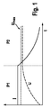
バッテリの充電プロセスの間にも、個々のバッテリセルまたはバッテリ全体の損傷を予防するために、バッテリ管理システムは常にバッテリの基本的なパラメータを監視している。図1は、リチウムイオンバッテリの従来技術で公知の充電プロセスの間のバッテリセルの充電電流Iおよびセル電圧Uの典型的な時間的推移を示している。第1の段階P1、いわゆるCC(CC:Constant Current、定電流)段階において、バッテリに定電流が充電され、したがって、バッテリセルのセル電圧が増大する。所定の限界電圧に到達して以降は、バッテリは、第2の段階P2、いわゆるCV(CV:Constant Voltage、定電圧)段階において、その値が例えば4.1Vのセル電圧に相当しクリティカルな最大セル電圧(停止限界値Umax)を下回る一定の電圧で引き続き充電される。充電電流は、この段階P2において近似的に指数的に低下する。所定の充電時間に到達しまたは充電電流の所定の値を下回り次第、充電プロセスは終了する。記載した充電ストラテジは、その特徴的な段階に倣ってCC−CV充電と呼ばれる。 During the battery charging process, the battery management system constantly monitors the basic parameters of the battery to prevent damage to individual battery cells or the entire battery. FIG. 1 shows a typical time course of battery cell charging current I and cell voltage U during a charging process known in the prior art for lithium ion batteries. In the first stage P1, the so-called CC (CC: Constant Current) stage, the battery is charged with a constant current, thus increasing the cell voltage of the battery cell. After reaching the predetermined limit voltage, the battery has a critical maximum corresponding to a cell voltage of, for example, 4.1 V in the second stage P2, the so-called CV (CV: Constant Voltage) stage. The battery is continuously charged at a constant voltage below the cell voltage (stop limit value U max ). The charging current decreases approximately exponentially at this stage P2. The charging process ends when a predetermined charging time is reached or as soon as the charging current falls below a predetermined value. The described charging strategy is called CC-CV charging following its characteristic stage.
充電プロセスの間に、バッテリのバッテリ管理システムは常に、バッテリをさらに細分化したバッテリモジュール内の温度、および、全セル電圧を監視する。最大セル温度または最大もしくは最小セル電圧(例えば、図1のUmax)について、所定の安全閾値を下回りまたは上回る場合のために、バッテリ管理システムは、バッテリの高電圧接触器を自動的に開放し、したがって、当該接触器を停止する(または電流が案内されない)。この安全機能は、極端な場合にはバッテリパックを不安定にしうる修復不可能な損傷から、バッテリを護るために必要である。(所定の作動温度を上回って)バッテリ温度が上昇する場合も、駆動中に大幅に予防されるべきである。なぜならば、このことが、バッテリパックの老朽化に拍車を掛かるからである。 During the charging process, the battery management system of the battery always monitors the temperature in the battery module that subdivides the battery and the total cell voltage. For cases where the maximum cell temperature or maximum or minimum cell voltage (eg, U max in FIG. 1) is below or above a predetermined safety threshold, the battery management system automatically opens the battery's high voltage contactor. Therefore, the contactor is stopped (or no current is guided). This safety feature is necessary to protect the battery from irreparable damage, which, in extreme cases, can destabilize the battery pack. If the battery temperature rises (above a predetermined operating temperature), it should also be largely prevented during driving. This is because this will spur the aging of the battery pack.
先に挙げた理由から、バッテリ管理システムは、充電プロセスの間にも継続的に、バッテリ充電のために利用される充電装置の制御装置に対して、セル電圧およびモジュール温度の値を報知する。充電プロセスの間に、熱損失のためにバッテリが温まる。充電プロセスの間にバッテリが許容される温度範囲から外れることを予防するために、バッテリを備える電気自動車の主制御装置によって、バッテリ温度が所定の限界値を上回り次第、空調用コンプレッサが作動される。 For the reasons mentioned above, the battery management system continuously informs the cell voltage and module temperature values to the controller of the charging device used for battery charging during the charging process. During the charging process, the battery warms up due to heat loss. In order to prevent the battery from going out of the allowable temperature range during the charging process, the main controller of the electric vehicle with the battery activates the air conditioning compressor as soon as the battery temperature exceeds a predetermined limit value. .
図2aは、バッテリ、空調用コンプレッサ、および、充電装置を備える全体システム内または当該システム上での、バッテリの充電工程の間の電流IGおよび電圧UGの時間的推移を示している。図2bは、バッテリ内またはバッテリ上の充電電流IBおよび充電電圧UBの同時の推移を示している。2つの時点t1およびt2において、空調用コンプレッサの作動プロセスが行われる。この作動プロセスは、短期間の間電流IGの上昇を必要とするが、この電流IGは、充電装置だけで提供することはできず、バッテリからも伝達される必要がある。このことによって結果的に、上記2つの時点において、充電電流IBが短時間の間落ちることになる。充電装置の制御装置は、充電電流の低下を測定し、直ちに充電電圧UBを上げることによって電力損失を補正する。作動プロセスの直後に、空調用コンプレッサは、より低い電流を極めて大量に必要とするため、作動プロセスの直後に、バッテリは、一段と高くなった充電電圧UBにより充電される(図2bの時点t1およびt2の直後のUBの急激な上昇を参照されたい)。バッテリの充電プロセスが、セル電圧が比較的低い段階(例えば、時点t1)に入っている場合については、このことは問題ではない。それに対して、バッテリの充電プロセスが、セル電圧がより高い段階(例えば、時点t2)に入っている場合については、最大セル電圧限界値を上回った結果として、制御できないバッテリ停止が発生する可能性がある。
Figure 2a is a battery, the air conditioning compressor, and, on the whole system or the system including the charging device, which is a temporal transition of the current I G and the voltage U G between the battery charging process. FIG. 2b shows the simultaneous transition of the charging current I B and the charging voltage U B in or on the battery. At two points in time t 1 and t 2 , the process of operating the air conditioning compressor takes place. The commissioning process will require an increase in current during I G short, the current I G can not be provided only by the charging device, it is necessary to also be transmitted from the battery. This by result, in the above two time points, so that the charging current I B falls for a short time. Control device of the charging device measures the decrease in the charging current, immediately to correct the power loss by increasing the charging voltage U B. Immediately after the actuation process, the air conditioning compressor requires a much larger amount of lower current, so that immediately after the actuation process, the battery is charged with a higher charging voltage U B (time t in FIG. 2b). see rapid rise in U B immediately after 1 and t 2). This is not a problem if the battery charging process is in a stage where the cell voltage is relatively low (eg, time t 1 ). In contrast, if the battery charging process is in a higher cell voltage stage (eg, time t 2 ), an uncontrollable battery outage may occur as a result of exceeding the maximum cell voltage limit. There is sex.
本発明によれば、バッテリ、特にリチウムイオンバッテリの充電プロセスを監視する方法が提供される。バッテリと、当該バッテリに充電電流を供給する充電モジュールと、少なくとも1つの追加的な電力消費機器が、電気回路の構成要素である。バッテリは、直列に接続された複数のバッテリセルを含む。本方法は以下の工程を含み、すなわち、複数のバッテリセルのセル電圧が定期的な時間間隔で測定され、バッテリへの負荷は、バッテリセルの測定されたセル電圧が所定のセル電圧閾値を上回る場合には、追加的な電力消費機器の作動プロセスにより予防される。これらの工程によって、最大セル電圧限界値を超えた結果としての、制御できないバッテリ停止が、追加的な消費機器の作動によって予防される。 According to the present invention, a method is provided for monitoring the charging process of a battery, particularly a lithium ion battery. A battery, a charging module that supplies a charging current to the battery, and at least one additional power consuming device are components of the electrical circuit. The battery includes a plurality of battery cells connected in series. The method includes the following steps: the cell voltages of a plurality of battery cells are measured at regular time intervals, and the load on the battery is such that the measured cell voltage of the battery cells exceeds a predetermined cell voltage threshold In some cases, it is prevented by the operation process of additional power consuming equipment. These steps prevent uncontrollable battery outages as a result of exceeding the maximum cell voltage limit by activation of additional consumer devices.
バッテリおよび追加的な消費機器は、車両の構成要素であり、車両の主制御装置は、追加的消費機器を駆動しうる。さらに、追加的な消費機器は、バッテリを冷却するための電気的冷却ユニット、特に空調用コンプレッサであってもよい。 The battery and the additional consuming device are components of the vehicle, and the main controller of the vehicle can drive the additional consuming device. Furthermore, the additional consumer device may be an electrical cooling unit for cooling the battery, in particular an air conditioning compressor.
本発明の好適な実施形態によれば、複数のバッテリのセル電圧に加えて、バッテリ充電電流およびバッテリの少なくとも1つの温度が定期的な時間間隔で測定され、セル電圧と、バッテリ充電電流と、温度とにしたがって、充電プロセスを中断せずに続行した際のバッテリ内の推定される最大温度に相当する推定値が定められ、推定値が所定の温度閾値を上回る場合には、電気的冷却ユニットが作動されるが、バッテリセルの測定されたセル電圧が所定のセル電圧閾値を上回る場合には、電気的冷却ユニットが作動されないことが構想される。これにより、バッテリの充電プロセスの時間的に早期の段階であって、セル電圧がセル電圧閾値を未だはるかに下回る傾向にある上記早期の段階、すなわち、冷却ユニットの作動が、最大セル電圧限界値を超えた結果としての制御できないバッテリ停止のリスクを未だ伴わない段階へと、冷却ユニットの作動を前にずらすことが達成される。 According to a preferred embodiment of the present invention, in addition to the cell voltages of a plurality of batteries, the battery charging current and at least one temperature of the battery are measured at regular time intervals, the cell voltage, the battery charging current, If the estimated value corresponding to the estimated maximum temperature in the battery when the charging process is continued without interruption is determined according to the temperature and the estimated value exceeds a predetermined temperature threshold, the electrical cooling unit It is envisioned that if the measured cell voltage of the battery cell is above a predetermined cell voltage threshold, the electrical cooling unit is not activated. This is an early stage of the battery charging process, where the cell voltage still tends to be well below the cell voltage threshold, i.e. the operation of the cooling unit is the maximum cell voltage limit value. It is achieved that the operation of the cooling unit is shifted forward to a stage that still does not involve the risk of uncontrollable battery shutdown as a result of exceeding
推定値の決定の際には、セル電圧のヒステリシスが考慮されうる。推定値は、バッテリ管理ユニットによって定められて、車両の主制御装置へと送信されうる。さらに、推定値は、バッテリ管理ユニットによって、CAN(Controller Area Network)バスを介して車両の主制御装置へと伝達されうる。 In determining the estimated value, hysteresis of the cell voltage can be taken into consideration. The estimated value can be determined by the battery management unit and transmitted to the main controller of the vehicle. Further, the estimated value can be transmitted by the battery management unit to the main controller of the vehicle via a CAN (Controller Area Network) bus.
本発明のさらなる別の観点は、バッテリ、好適にリチウムイオンバッテリと、当該バッテリと接続されたバッテリ管理ユニットとを備えたバッテリシステムであって、バッテリは、直列に接続された複数のバッテリセルを含む、上記バッテリシステムに関する。バッテリ管理ユニットは、各バッテリセルのセル電圧を測定するよう構成された複数の電圧測定ユニットと、バッテリの温度を測定するよう構成された少なくとも1つの温度測定ユニットと、バッテリ充電電流を測定するよう構成された少なくとも1つの電流測定ユニットと、電圧測定ユニットおよび温度測定ユニットおよび電流測定ユニットと接続されたコントローラとを有する。コントローラは、バッテリの充電プロセスの間に、バッテリ充電電流と、セル電圧と、温度とにしたがって、充電プロセスを中断せずに続行した際のバッテリ内の最大温度に相当する推定値を定めるよう構成される。これにより、バッテリシステムを備える全体システムにおいて、推定値に基づいて、バッテリの充電プロセスの時間的に早期の段階であって、セル電圧がセル電圧閾値を未だはるかに下回る傾向にある上記早期の段階、すなわち、冷却ユニットの作動が、最大セル電圧限界値を超えた結果としての制御できないバッテリ停止のリスクを伴わない段階へと、バッテリを冷却するための冷却ユニットの作動を前にずらすことが達成される。 Yet another aspect of the present invention is a battery system comprising a battery, preferably a lithium ion battery, and a battery management unit connected to the battery, wherein the battery comprises a plurality of battery cells connected in series. Including the battery system. The battery management unit is configured to measure a battery charge current, a plurality of voltage measurement units configured to measure a cell voltage of each battery cell, at least one temperature measurement unit configured to measure a temperature of the battery. At least one current measurement unit configured and a controller connected to the voltage measurement unit, the temperature measurement unit and the current measurement unit. The controller is configured to determine an estimate during the battery charging process according to the battery charging current, cell voltage, and temperature that corresponds to the maximum temperature in the battery when the charging process is continued without interruption. Is done. Thus, in the overall system including the battery system, based on the estimated value, it is an early stage of the battery charging process, and the cell voltage still tends to be far below the cell voltage threshold. I.e. moving the cooling unit forward to cool the battery to a stage where the cooling unit operation does not involve the risk of uncontrollable battery shutdown as a result of exceeding the maximum cell voltage limit Is done.
バッテリの様々な領域内の温度を測定するよう構成された複数の温度測定ユニットが、バッテリ内に配置されうる。推定値の決定の際には、セル電圧のヒステリシスが考慮されうる。さらに、推定値は、バッテリ管理ユニットのインタフェース、特にCANインタフェースを介して出力されうる。 A plurality of temperature measurement units configured to measure temperatures in various areas of the battery may be disposed within the battery. In determining the estimated value, hysteresis of the cell voltage can be taken into consideration. Furthermore, the estimated value can be output via the interface of the battery management unit, in particular the CAN interface.
本発明のさらなる別の観点は、バッテリ、好適にリチウムイオンバッテリおよび当該バッテリと接続されたバッテリ管理ユニットを含むバッテリシステムと、主制御装置と、少なくとも1つの追加的な電力消費機器とを備えた車両であって、バッテリシステムは車両の駆動システムと接続され、主制御装置は追加的な消費機器を駆動する、上記車両に関する。車両は、バッテリの充電プロセスの間に本発明に係る方法を実施するよう構成される。好適な実施形態において、車両は、本発明に係るバッテリシステムを備える。 Yet another aspect of the invention comprises a battery, preferably a lithium ion battery and a battery system including a battery management unit connected to the battery, a main controller, and at least one additional power consuming device. A vehicle, wherein the battery system is connected to a drive system of the vehicle, and the main control device relates to the vehicle that drives an additional consumer device. The vehicle is configured to perform the method according to the invention during the battery charging process. In a preferred embodiment, the vehicle includes a battery system according to the present invention.
本発明の実施例は、図面、および、以下の明細書の記載を用いてより詳細に記載される。
本発明に係る方法の一実施例を示している。本方法は、車両内に配置された一実施例のバッテリの充電プロセスの監視のために役立つ。さらに、車両は、バッテリの冷却のために適した、追加的な消費機器としての空調用コンプレッサと、当該空調用コンプレッサを制御する主制御装置とを備える。本方法は、工程S10において開始される。工程S11では、バッテリの充電プロセスの間に、直列に接続された複数のバッテリセルのセル電圧と、バッテリ充電電流と、バッテリの様々な領域内の複数の温度とが測定される。工程S12において、バッテリ充電電流と、セル電圧と、温度とにしたがって、充電プロセスを中断せずに空調用コンプレッサを作動させずに続行した場合にバッテリの一領域内で到達しうるバッテリ内の仮定的最大温度が推定される。空調用コンプレッサが作動されない限りにおいてCC−CV充電の終了までにバッテリ内で発生しうるバッテリセル内の最大温度を、示された測定値から予測する予測機能が、仮定的最大温度の値を計算するために、バッテリのバッテリ管理システムのソフトウェアに組み込まれてもよい。予測機能は、充電プロセスおよび放電プロセスの間セル電圧が開放電圧とは異なることを特徴とするバッテリセル内のヒステリシスを考慮することが可能である。その際に、各充電電流または放電電流が高いほど、ヒステリシスの高さは高くなる。上記のパラメータにしたがって最大温度を予測するためのモデルは、第1のプロトタイプバッテリ上での以前の測定により定められる。 1 shows an embodiment of the method according to the invention. The method is useful for monitoring the charging process of an example battery located in a vehicle. Further, the vehicle includes an air conditioning compressor as an additional consumer device suitable for cooling the battery, and a main controller that controls the air conditioning compressor. The method starts at step S10. In step S11, during the battery charging process, the cell voltages of the battery cells connected in series, the battery charging current, and the temperatures in various regions of the battery are measured. In step S12, an assumption in the battery that can be reached in a region of the battery if the charging process is continued without activating the air conditioning compressor according to the battery charging current, cell voltage, and temperature. The maximum temperature is estimated. Predictive function that predicts the maximum temperature in the battery cell that can occur in the battery by the end of CC-CV charge from the indicated measurement value, unless the air conditioning compressor is activated, calculates the value of the hypothetical maximum temperature In order to do so, it may be incorporated into the battery management system software of the battery. The prediction function can take into account hysteresis in the battery cell, characterized in that the cell voltage differs from the open circuit voltage during the charging and discharging process. At that time, the higher the charge current or discharge current, the higher the hysteresis. A model for predicting the maximum temperature according to the above parameters is defined by previous measurements on the first prototype battery.
工程S13において、主制御装置によって、バッテリ内の推定される仮定的最大温度が所定の温度閾値と比較され、この所定の温度閾値は、バッテリの不可逆的損傷を予防するためにバッテリ内で超えるべきでない温度に相当する。バッテリ内の推定される仮定的最大温度が、所定の温度閾値よりも大きくない場合には、本方法の開始、すなわち工程S11へと戻り、バッテリ内の推定される仮定的最大温度が所定の温度閾値よりも大きい場合には、工程S14において、主制御装置によって、測定されたどのセル電圧も、所定のセル電圧閾値よりも高くないかどうかが検査される。測定されたどのセル電圧も、所定のセル電圧閾値よりも高くない場合には、工程S15において、バッテリの冷却のために適した空調用コンプレッサが、主制御装置によって作動される。 In step S13, the main controller compares the estimated maximum temperature in the battery with a predetermined temperature threshold, which should be exceeded in the battery to prevent irreversible damage to the battery. Corresponds to a temperature that is not. If the estimated hypothetical maximum temperature in the battery is not greater than the predetermined temperature threshold, return to the start of the method, ie, step S11, where the estimated hypothetical maximum temperature in the battery is the predetermined temperature. If greater than the threshold, in step S14, the main controller checks whether any measured cell voltage is higher than a predetermined cell voltage threshold. If none of the measured cell voltages are higher than the predetermined cell voltage threshold, in step S15, an air conditioning compressor suitable for battery cooling is activated by the main controller.
これに対して、少なくとも1つの測定されたセル電圧が、所定のセル電圧閾値よりも高い場合には、工程S16において制御装置によって、S15で空調用コンプレッサが作動される前に、バッテリの充電プロセスが中止され、または、バッテリが電気的に分離される。したがって、少なくともバッテリの充電プロセスの間には、空調用コンプレッサによる電力消費がブロックされ、空調用コンプレッサの電力消費のために必要な電流がバッテリによっても伝達されることが予防される。 On the other hand, if the at least one measured cell voltage is higher than the predetermined cell voltage threshold, the battery charging process before the air conditioning compressor is activated in S15 by the controller in step S16. Is stopped or the battery is electrically isolated. Therefore, at least during the battery charging process, power consumption by the air conditioning compressor is blocked, and current necessary for power consumption of the air conditioning compressor is prevented from being transmitted also by the battery.
図4は、全体として符号30が付された本発明に係るバッテリシステムの一実施例を示す。バッテリ20は、直列に接続された複数のバッテリセル21を含む。バッテリセルの各セル電圧を測定する複数の電圧測定ユニット22が設けられる。さらに、温度測定ユニット23が、バッテリの様々な領域に配置される。電流測定ユニット24は、バッテリ20の充電プロセスの間、バッテリ充電電流を測定する。電圧測定ユニット22、温度測定ユニット23、および電流測定ユニット24は、コントローラ25と接続されており、このコントローラ25は、バッテリの充電プロセスの間に、電圧測定ユニット22および温度測定ユニット23および電流測定ユニット24から伝達された測定値にしたがって、充電プロセスを中断せずに空調用コンプレッサを作動させずに続行した場合の、バッテリ内の仮定的最大温度を推定するよう構成されている。コントローラ25は、図3で記載された方法のように、仮定的最大温度の計算を行うよう構成される。
FIG. 4 shows an embodiment of a battery system according to the present invention generally designated by
図5は、本発明に係る車両の一実施例における、本発明に係るバッテリシステム30の接続を示す。図4で示される本発明に係るバッテリシステム30と、車両の主制御装置32と、バッテリシステム30に充電電流を供給する、本発明に係る車両の必須構成要素ではない充電モジュール33とは、共通のバスシステム、特にCANバス31上に存在する。バッテリシステム30、充電モジュール33、および空調用コンプレッサ34は、電気回路の構成要素として互いに接続され、その際に、3つの構成要素全てが並列に接続される。本発明に係るバッテリシステム30のバッテリ管理ユニットは、CANバス31を介して実時間で車両の主制御装置32へと、以下の値を送信し、周期的に更新する。
(1)バッテリ20内の最大セル電圧値;
(2)バッテリ20内の最小セル電圧値;および
(3)充電プロセスを中断せずに空調用コンプレッサ34を作動させずに続行した場合にバッテリ20内の領域内で到達しうるバッテリ20内の仮定的最大温度。
FIG. 5 shows the connection of the
(1) Maximum cell voltage value in the
(2) the minimum cell voltage value in the
本発明に係るバッテリシステム30のバッテリ管理ユニットによって車両の主制御装置32へと送信されたバッテリ20内の仮定的最大温度が、所定の温度閾値を上回る場合には、車両の主制御装置32は、以下に挙げる条件を前提に、空調用コンプレッサ34を作動させる。
When the assumed maximum temperature in the
バッテリ20のCC−CV充電の間に空調用コンプレッサ34が作動される場合には、この空調用コンプレッサ34は、短時間の間、例えば50Aの電流を必要とする。この電流は、充電モジュール33だけでは提供することができず、バッテリシステム30によっても伝達される必要があり、これにより、充電電流が落ちる。この低下は、基本的に車両の主制御装置32によって検知されて、充電モジュール33のレギュレータに報知され、これに応じて、充電モジュール33のレギュレータは、充電電圧の上昇を介して釣り合いを取るが、このことは、セル電圧値が所定のセル電圧閾値を上回るバッテリセル21を損傷させる可能性があり、または、バッテリ管理ユニットによる、制御できないバッテリ20の停止に繋がる可能性がある。
When the
したがって、その代わりに、本発明に係る車両の主制御装置32は、本発明に係るバッテリシステム30のバッテリ管理ユニットによって車両の主制御装置32へと送信されたバッテリ20内の最大セル電圧値が所定のセル電圧閾値を上回る場合には、空調用コンプレッサ34を作動させない。
Therefore, instead, the main control device 32 of the vehicle according to the present invention has the maximum cell voltage value in the
Claims (10)
−前記バッテリ(20)と、前記バッテリ(20)に充電電流を供給する充電モジュール(33)と、少なくとも1つの追加的な電力消費機器(34)が、電気回路の構成要素であり、
−前記バッテリ(20)は、直列に接続された複数のバッテリセル(21)を含み、
−複数のバッテリセル(21)のセル電圧が定期的な時間間隔で測定される(S11)、前記監視する方法において、
前記バッテリ(20)への負荷は、バッテリセル(21)の測定された前記セル電圧が所定のセル電圧閾値を上回る場合には(S14)、前記追加的な電力消費機器を作動させないことにより予防され(S16)、
前記追加的な消費機器(34)は、前記バッテリ(20)を冷却するための電気的冷却ユニットであり、
−複数のバッテリセル(21)の前記セル電圧に加えて、バッテリ充電電流および前記バッテリ(21)の少なくとも1つの温度が定期的な時間間隔で測定され(S11)、
−前記セル電圧と、前記バッテリ充電電流と、前記温度とにしたがって、前記充電プロセスを中断せずに続行した際の前記バッテリ(20)内の推定される最大温度に相当する推定値が定められ(S12)、
−前記推定値が所定の温度閾値を上回る場合には(S13)、前記電気的冷却ユニット(34)が作動されるが(S15)、バッテリセル(21)の前記測定されたセル電圧が前記所定のセル電圧閾値を上回る場合には(S14)、前記電気的冷却ユニット(34)が作動されないことを特徴とする、
バッテリ(20)の充電プロセスを監視する方法。 A method for monitoring a charging process of a battery (20), comprising:
The battery (20), a charging module (33) for supplying a charging current to the battery (20), and at least one additional power consuming device (34) are components of an electrical circuit;
The battery (20) comprises a plurality of battery cells (21) connected in series;
- cell voltages of the plurality of battery cells (21) is measured at regular time intervals (S11), a method of the monitoring,
The load on the battery (20) is prevented by not to operate the (S14), the additional power consumption device when said measured cell voltage of the battery cell (21) exceeds a predetermined cell voltage threshold ( S16 ),
The additional consumer device (34) is an electrical cooling unit for cooling the battery (20);
-In addition to the cell voltage of a plurality of battery cells (21), a battery charging current and at least one temperature of the battery (21) are measured at regular time intervals (S11);
An estimated value corresponding to the estimated maximum temperature in the battery (20) when the charging process is continued without interruption is determined according to the cell voltage, the battery charging current and the temperature; (S12),
-If the estimated value exceeds a predetermined temperature threshold (S13), the electrical cooling unit (34) is activated (S15), but the measured cell voltage of the battery cell (21) is When the cell voltage threshold is exceeded (S14), the electrical cooling unit (34) is not activated .
A method for monitoring a charging process of a battery (20).
前記車両の主制御装置(32)が、前記追加的な消費機器(34)を駆動する、請求項1に記載の方法。 The battery (21) and the additional consumer device (34) are vehicle components,
The method according to claim 1, wherein the main controller (32) of the vehicle drives the additional consumer device (34).
前記バッテリシステムは、前記車両の駆動システムと接続され、前記主制御装置(32)は、前記追加的な消費機器(34)を駆動する、前記車両において、
前記車両は、前記バッテリの充電プロセスの間に請求項1〜5のいずれか1項に記載の方法を実施するよう構成されることを特徴とする、車両。 A vehicle comprising a battery system (30) including a battery (20) and a battery management unit connected to the battery, a main controller (32), and at least one additional power consuming device (34). There,
In the vehicle, the battery system is connected to a drive system of the vehicle, and the main controller (32) drives the additional consumer device (34),
A vehicle, characterized in that the vehicle is configured to perform the method of any one of claims 1 to 5 during the battery charging process.
前記バッテリ管理ユニットは、The battery management unit includes:
各バッテリセル(21)のセル電圧を測定するよう構成された複数の電圧測定ユニット(22)と、A plurality of voltage measurement units (22) configured to measure a cell voltage of each battery cell (21);
前記バッテリの温度を測定するよう構成された少なくとも1つの温度測定ユニット(23)と、At least one temperature measuring unit (23) configured to measure the temperature of the battery;
バッテリ充電電流を測定するよう構成された少なくとも1つの電流測定ユニット(24)と、At least one current measurement unit (24) configured to measure battery charge current;
前記電圧測定ユニット(22)および前記温度測定ユニット(23)および前記電流測定ユニット(24)と接続されたコントローラ(25)と、A controller (25) connected to the voltage measurement unit (22), the temperature measurement unit (23) and the current measurement unit (24);
を有し、Have
前記コントローラ(25)は、前記バッテリ(20)の充電プロセスの間に、前記バッテリ充電電流と、前記セル電圧と、前記温度とにしたがって、前記充電プロセスを中断せずに続行した際の前記バッテリ(20)内の最大温度に相当する推定値を定めるよう構成される、請求項6に記載の車両。The controller (25), during the charging process of the battery (20), according to the battery charging current, the cell voltage, and the temperature, the battery when the charging process is continued without interruption The vehicle according to claim 6, configured to determine an estimated value corresponding to a maximum temperature in (20).
Applications Claiming Priority (3)
| Application Number | Priority Date | Filing Date | Title |
|---|---|---|---|
| DE102010030548.0 | 2010-06-25 | ||
| DE201010030548 DE102010030548A1 (en) | 2010-06-25 | 2010-06-25 | Method for monitoring a charging process of a battery |
| PCT/EP2011/057535 WO2011160891A2 (en) | 2010-06-25 | 2011-05-10 | Method for monitoring a charging process of a battery |
Publications (2)
| Publication Number | Publication Date |
|---|---|
| JP2013535077A JP2013535077A (en) | 2013-09-09 |
| JP5567741B2 true JP5567741B2 (en) | 2014-08-06 |
Family
ID=44119027
Family Applications (1)
| Application Number | Title | Priority Date | Filing Date |
|---|---|---|---|
| JP2013515786A Active JP5567741B2 (en) | 2010-06-25 | 2011-05-10 | Method for monitoring battery charging process, battery system, and vehicle |
Country Status (8)
| Country | Link |
|---|---|
| US (1) | US9231418B2 (en) |
| EP (1) | EP2586089B1 (en) |
| JP (1) | JP5567741B2 (en) |
| KR (2) | KR101742254B1 (en) |
| CN (1) | CN102959790B (en) |
| DE (1) | DE102010030548A1 (en) |
| ES (1) | ES2656870T3 (en) |
| WO (1) | WO2011160891A2 (en) |
Families Citing this family (13)
| Publication number | Priority date | Publication date | Assignee | Title |
|---|---|---|---|---|
| DE102011084688B4 (en) * | 2011-10-18 | 2022-06-30 | Robert Bosch Gmbh | battery system |
| FR2983354B1 (en) * | 2011-11-24 | 2015-12-18 | Renault Sas | METHOD FOR REGULATING THE TEMPERATURE OF A TRACTION BATTERY OF A CHARGED ELECTRIC VEHICLE, PARTICULARLY DURING RAPID CHARGING OF THE BATTERY |
| JP5884677B2 (en) * | 2012-08-21 | 2016-03-15 | 株式会社豊田自動織機 | Charging method and charging device |
| DE102013213267A1 (en) * | 2013-07-05 | 2015-01-08 | Robert Bosch Gmbh | Method for battery management and battery management system |
| DE102013215357A1 (en) | 2013-08-05 | 2015-02-05 | Robert Bosch Gmbh | Method and device for monitoring at least one state parameter of a battery of a parked vehicle |
| KR101854218B1 (en) * | 2013-10-22 | 2018-05-03 | 삼성에스디아이 주식회사 | Battery pack, energy storage system, and method of charging the battery pack |
| KR102667239B1 (en) * | 2015-07-27 | 2024-05-17 | 삼성전자주식회사 | Method and a battery system for thermal management |
| DE102015220692A1 (en) * | 2015-10-22 | 2017-04-27 | Bayerische Motoren Werke Aktiengesellschaft | Method and control unit for accelerating a charging process of an electrical energy store |
| KR102145651B1 (en) * | 2016-08-26 | 2020-08-18 | 주식회사 엘지화학 | Battery management system |
| FR3077378B1 (en) * | 2018-01-31 | 2020-05-22 | Valeo Systemes Thermiques | THERMAL REGULATION SYSTEM FOR AT LEAST ONE ELECTRIC STORAGE DEVICE OF A MOTOR VEHICLE |
| CN109581239A (en) * | 2018-11-26 | 2019-04-05 | 漳州市华威电源科技有限公司 | A kind of accumulator management device and monitoring system |
| CN113178922A (en) * | 2021-05-13 | 2021-07-27 | 浙江特康电子科技有限公司 | Charging control method, system and device and charging device |
| FR3129776A1 (en) * | 2021-11-29 | 2023-06-02 | Valeo Systemes Thermiques | OPTIMIZED COOLING PROCESS FOR AN ELECTRIC OR HYBRID VEHICLE BATTERY |
Family Cites Families (9)
| Publication number | Priority date | Publication date | Assignee | Title |
|---|---|---|---|---|
| US5179337A (en) * | 1991-11-13 | 1993-01-12 | International Business Machines Corporation | Over-discharge protection for rechargeable batteries |
| US5652501A (en) * | 1994-12-12 | 1997-07-29 | Unitrode Corporation | Voltage sensor for detecting cell voltages |
| US6285161B1 (en) * | 2000-09-11 | 2001-09-04 | O2 Micro International Limited | Battery cell charging system having voltage threshold and bleeder current generating circuits |
| DE502004005703D1 (en) * | 2004-05-28 | 2008-01-24 | Catem Develec Gmbh | Electronic battery protection switch |
| JP2007195272A (en) * | 2006-01-17 | 2007-08-02 | Toyota Motor Corp | Controller of battery pack |
| US7656633B2 (en) * | 2006-12-26 | 2010-02-02 | Hamilton Sundstrand Corporation | Asymmetric fault detection and protection with AC solid state power controllers |
| JP5091634B2 (en) * | 2007-11-15 | 2012-12-05 | パナソニック株式会社 | Battery pack and charging system |
| JP5219485B2 (en) | 2007-12-12 | 2013-06-26 | 三洋電機株式会社 | Charging method |
| US8847554B2 (en) * | 2009-06-10 | 2014-09-30 | K2 Energy Solutions, Inc. | System for preventing deep battery discharge |
-
2010
- 2010-06-25 DE DE201010030548 patent/DE102010030548A1/en not_active Withdrawn
-
2011
- 2011-05-10 JP JP2013515786A patent/JP5567741B2/en active Active
- 2011-05-10 EP EP11719534.7A patent/EP2586089B1/en active Active
- 2011-05-10 US US13/806,108 patent/US9231418B2/en active Active
- 2011-05-10 KR KR1020147036992A patent/KR101742254B1/en active IP Right Grant
- 2011-05-10 ES ES11719534.7T patent/ES2656870T3/en active Active
- 2011-05-10 CN CN201180031008.9A patent/CN102959790B/en active Active
- 2011-05-10 KR KR1020137002146A patent/KR101600043B1/en active IP Right Grant
- 2011-05-10 WO PCT/EP2011/057535 patent/WO2011160891A2/en active Application Filing
Also Published As
| Publication number | Publication date |
|---|---|
| EP2586089B1 (en) | 2017-10-25 |
| CN102959790A (en) | 2013-03-06 |
| KR20130031365A (en) | 2013-03-28 |
| US20130207464A1 (en) | 2013-08-15 |
| KR101600043B1 (en) | 2016-03-04 |
| EP2586089A2 (en) | 2013-05-01 |
| CN102959790B (en) | 2016-03-30 |
| DE102010030548A1 (en) | 2011-12-29 |
| WO2011160891A2 (en) | 2011-12-29 |
| US9231418B2 (en) | 2016-01-05 |
| KR101742254B1 (en) | 2017-05-31 |
| ES2656870T3 (en) | 2018-02-28 |
| JP2013535077A (en) | 2013-09-09 |
| KR20150015538A (en) | 2015-02-10 |
| WO2011160891A3 (en) | 2012-06-28 |
Similar Documents
| Publication | Publication Date | Title |
|---|---|---|
| JP5567741B2 (en) | Method for monitoring battery charging process, battery system, and vehicle | |
| US20200280204A1 (en) | Battery control device | |
| US10840722B2 (en) | Battery control device | |
| EP2133974B1 (en) | Accumulation system | |
| JP7106362B2 (en) | Storage battery charge/discharge curve estimation device and charge/discharge curve estimation method | |
| US7768235B2 (en) | Battery management system and method for automotive vehicle | |
| KR102052241B1 (en) | System and method for battery management using Balancing battery | |
| US9496734B2 (en) | Charge control apparatus for vehicle | |
| US8004239B2 (en) | Battery management system for calculating charge and disharge powers | |
| WO2013094057A1 (en) | Battery control device and battery system | |
| EP2717415A1 (en) | Electricity storage system | |
| US20100174417A1 (en) | Power supply system, and power supply control method and power supply control program employed in power supply system | |
| WO2012169062A1 (en) | Battery control device and battery system | |
| US9680320B2 (en) | Battery control apparatus | |
| JP2004222427A (en) | Charge control device, battery management system, battery pack, and impairment determination method of rechargeable battery by them | |
| KR20130126918A (en) | Battery management system for a power supply system with a low-voltage region and a high-voltage region | |
| CN109075401A (en) | Battery pack and the method to charge to battery pack | |
| US11332017B2 (en) | Method and a device for controlling the operation of an energy storage system in a vehicle | |
| KR102014719B1 (en) | Battery life management device | |
| JP6648539B2 (en) | Power storage system | |
| JP2004172058A (en) | Battery management system and battery pack | |
| JP2012034425A (en) | Charging/discharging control circuit of secondary battery, battery pack, and battery power supply system | |
| JP2011155784A (en) | Secondary battery system and method of managing the same | |
| KR20210044029A (en) | Energy Balancing Method in Parallel Battery Packs using Energy Difference before Operation between Multi-Packs Comprising the Same and the Control System Thereof | |
| JP2013146159A (en) | Charge control system and charge control method of battery pack |
Legal Events
| Date | Code | Title | Description |
|---|---|---|---|
| A131 | Notification of reasons for refusal |
Free format text: JAPANESE INTERMEDIATE CODE: A131 Effective date: 20131112 |
|
| A601 | Written request for extension of time |
Free format text: JAPANESE INTERMEDIATE CODE: A601 Effective date: 20140212 |
|
| A602 | Written permission of extension of time |
Free format text: JAPANESE INTERMEDIATE CODE: A602 Effective date: 20140219 |
|
| A521 | Request for written amendment filed |
Free format text: JAPANESE INTERMEDIATE CODE: A523 Effective date: 20140325 |
|
| TRDD | Decision of grant or rejection written | ||
| A01 | Written decision to grant a patent or to grant a registration (utility model) |
Free format text: JAPANESE INTERMEDIATE CODE: A01 Effective date: 20140520 |
|
| A61 | First payment of annual fees (during grant procedure) |
Free format text: JAPANESE INTERMEDIATE CODE: A61 Effective date: 20140619 |
|
| R150 | Certificate of patent or registration of utility model |
Ref document number: 5567741 Country of ref document: JP Free format text: JAPANESE INTERMEDIATE CODE: R150 |
|
| R250 | Receipt of annual fees |
Free format text: JAPANESE INTERMEDIATE CODE: R250 |
|
| R250 | Receipt of annual fees |
Free format text: JAPANESE INTERMEDIATE CODE: R250 |
|
| R250 | Receipt of annual fees |
Free format text: JAPANESE INTERMEDIATE CODE: R250 |
|
| R250 | Receipt of annual fees |
Free format text: JAPANESE INTERMEDIATE CODE: R250 |
|
| R250 | Receipt of annual fees |
Free format text: JAPANESE INTERMEDIATE CODE: R250 |
|
| R250 | Receipt of annual fees |
Free format text: JAPANESE INTERMEDIATE CODE: R250 |
|
| R250 | Receipt of annual fees |
Free format text: JAPANESE INTERMEDIATE CODE: R250 |
|
| R250 | Receipt of annual fees |
Free format text: JAPANESE INTERMEDIATE CODE: R250 |