JP5567030B2 - Ferro-electret two-layer and multilayer composite and method for producing the same - Google Patents
Ferro-electret two-layer and multilayer composite and method for producing the same Download PDFInfo
- Publication number
- JP5567030B2 JP5567030B2 JP2011539920A JP2011539920A JP5567030B2 JP 5567030 B2 JP5567030 B2 JP 5567030B2 JP 2011539920 A JP2011539920 A JP 2011539920A JP 2011539920 A JP2011539920 A JP 2011539920A JP 5567030 B2 JP5567030 B2 JP 5567030B2
- Authority
- JP
- Japan
- Prior art keywords
- polymer film
- film
- polymer
- composite
- voids
- Prior art date
- Legal status (The legal status is an assumption and is not a legal conclusion. Google has not performed a legal analysis and makes no representation as to the accuracy of the status listed.)
- Expired - Fee Related
Links
Images


Description
本発明は、規定の空隙を持つ2層および多層フェロエレクトレットの製造方法、およびこれらの製造方法により製造されたフェロエレクトレット多層コンポジットに関する。 The present invention relates to a method for producing two-layer and multilayer ferroelectrets having defined voids, and a ferroelectret multilayer composite produced by these production methods.
その有効で選択的に調節可能な特性のために、たとえば、軽量、熱伝導性、機械的変形性、電気特性だけでなく、遮断特性のために、ポリマーおよびポリマーコンポジット材料は多くの一般的用途で使用される。たとえば、これらは食品や他の商品用パッケージ材料として、たとえば、建設工学や自動車工学における建設材料または絶縁材料として使用される。しかし、機能性ポリマーはセンサ用途やアクチュエータ用途における動的部品としての重要性も広がっている。この関連で重要な用途概念は、電気機械的または圧電的変換器としてこのポリマーを使用することに関する。圧電材料は、機械的圧力を線形的に電圧信号に変えることができる。逆に、圧電材料に加えられた電場を、変換器の形状の変化に変換することができる。圧電材料は、多くの用途において、これまでも動的部品として組み込まれている。これらの部品には、たとえば、キーボードまたはタッチパッド用構造圧力センサ、加速センサ、マイク、拡声器、医療工学、海洋工学または材料試験における用途のための超音波変換器がある。国際特許出願第WO 2006/053528号公報には、たとえば、ポリマーフィルムからなる圧電素子に基づく電子音響変換器が記載されている。 Because of its effective and selectively adjustable properties, for example, light weight, thermal conductivity, mechanical deformability, electrical properties, as well as barrier properties, polymers and polymer composite materials have many common applications Used in. For example, they are used as food and other commodity packaging materials, for example as construction materials or insulation materials in construction engineering and automotive engineering. However, functional polymers are also gaining importance as dynamic parts in sensor and actuator applications. An important application concept in this context relates to the use of this polymer as an electromechanical or piezoelectric transducer. Piezoelectric materials can convert mechanical pressure into a voltage signal linearly. Conversely, the electric field applied to the piezoelectric material can be converted into a change in the shape of the transducer. Piezoelectric materials have been incorporated as dynamic components in many applications. These components include, for example, structural pressure sensors for keyboards or touchpads, acceleration sensors, microphones, loudspeakers, ultrasonic transducers for use in medical engineering, marine engineering or material testing. International patent application WO 2006/053528 describes an electroacoustic transducer based on a piezoelectric element made of a polymer film, for example.
近年、フェロエレクトレットと呼ばれる、新しい種類の圧電性ポリマーが、次第に研究対象となってきている。フェロエレクトレットは、ピエゾエレクトレットとも呼ばれている。フェロエレクトレットは、電荷を長時間保持できる空隙構造を有するポリマー材料からなる。これまで知られているフェロエレクトレットは、セル状空隙構造を有し、発泡ポリマーフィルムとして、あるいはポリマーフィルムまたはポリマー織物から成る多層系として、形成される。電荷が空隙の様々な表面にそれらの極性に応じて分布されるなら、各帯電空隙は電気双極子に相当する。そして、空隙が変形されると、双極子の大きさに変化が生じ、外部電極間に電流が流れることになる。フェロエレクトレットは、他の圧電材料に匹敵する圧電活性を示し得る。 In recent years, new types of piezoelectric polymers, called ferroelectrets, have been increasingly studied. Ferro electrets are also called piezo electrets. The ferroelectret is made of a polymer material having a void structure that can hold a charge for a long time. The ferroelectrets known so far have a cellular void structure and are formed as a foamed polymer film or as a multilayer system composed of polymer films or polymer fabrics. If charge is distributed on the various surfaces of the air gap according to their polarity, each charged air gap corresponds to an electric dipole. When the gap is deformed, the dipole size changes, and a current flows between the external electrodes. Ferro electrets can exhibit piezoelectric activity comparable to other piezoelectric materials.
米国特許第US 4,654,546号公報には、フェロエレクトレットフィルムの前段階として、ポリプロピレン発泡フィルムを製造することが記載されている。この場合には、ポリマーフィルムを充填材粒子と混合する。充填材としては、たとえば、二酸化チタンが使用される。押出し後、ポリプロピレンフィルムを二軸延伸すると、フィルム内部には充填材粒子の周囲に小さい空隙が形成される。この方法は、他のポリマーに応用することもできる。たとえば、M.ベゲナー(Wegener),M.パージャネン(Paajanen),O.ボロニーナ(Voronina),R.シュルゼ(Schulze),W.ウィルゲス(Wirges),およびR.ゲハード−マルトープ(Gerhard-Multhaupt)「空隙シクロオレフィンポリマーフィルム(Voided cyclo-olefin polymer films):高い熱安定性を有するフェロエレクトレット(ferroelectrets with high thermal stability)」,議事録,第12回エレクトレット国際シンポジウム(IEEEサービスセンター,ピスカタウェイ,ニュージャージー,USA 2005),47−50(2005)およびエッタ・サーリマエキ(Eetta Saarimaeki),ミカ・パージャネン(Mika Paajanen),アン−マリ・サビジャエルビ(Ann-Mari Savijaervi),およびハンヌ・ミンキネン(Hannu Minkkinen),ミカエル・ウェグナー(Michael Wegener),オレンナ・ボロニナ(Olena Voronina),ロベルト・シュルゼ(Robert Schulze),ウェルナー・ウィルゲス(Werner Wirges)およびレイマンド・ゲハード−マルトープ(Reimund Gerhard-Multhaupt)「新規の熱耐性電気機械的フィルム(Novel Heat Durable Electromechanical Film):電気機械的およびエレクトレット用途用処理(Processing for Electromechanical and Electret Applications)」,誘電性および電気絶縁体IEEE議事録(Transactions on Dielectrics and Electrical Insulation)13,963−972(2006年10月)には、シクロオレフィンコポリマー(COC)およびシクロオレフィンポリマー(COP)からのフェロエレクトレットフィルムの製造が記載されている。発泡ポリマーフィルムは、気泡サイズ分布が幅広いという欠点を有する。その結果、全ての気泡が、後の帯電工程において均一に帯電されるということはない。 US Pat. No. 4,654,546 describes the production of a polypropylene foam film as a pre-stage of a ferroelectret film. In this case, the polymer film is mixed with the filler particles. As the filler, for example, titanium dioxide is used. When the polypropylene film is biaxially stretched after extrusion, small voids are formed around the filler particles inside the film. This method can also be applied to other polymers. For example, M.M. Wegener, M.C. Paajanen, O. Voronina, R.A. Schulze, W.C. Wilges, and R.W. Gerhard-Multhaupt “Voided cyclo-olefin polymer films: Ferrolectrets with high thermal stability”, Proceedings, 12th Electret International Symposium ( IEEE Service Center, Piscataway, New Jersey, USA 2005), 47-50 (2005) and Eetta Saarimaeki, Mika Paajanen, Ann-Mari Savijaervi, and Hanne Hannu Minkkinen, Michael Wegener, Olena Voronina, Robert Schulze, Werner Wirges and Reimund Gerh ard-Multhaupt) "Novel Heat Durable Electromechanical Film: Processing for Electromechanical and Electret Applications", Dielectric and Electrical Insulators IEEE Transactions (Transactions on Dielectrics and Electrical Insulation, 13,963-972 (October 2006), describes the production of ferroelectret films from cycloolefin copolymers (COC) and cycloolefin polymers (COP). Foamed polymer films have the disadvantage of a wide bubble size distribution. As a result, all the bubbles are not uniformly charged in the subsequent charging step.
発泡フェロエレクトレットポリマーフィルムのさらなる製造方法は、超臨界液体、たとえば、二酸化炭素を用いて均一なフィルムに直接物理的に泡形成するものである。アドバンスド・ファンクショナル・マテリアルズ(Advanced Functional Materials)17,324−329(2007),ウェルナー・ウィルゲス(Werner Wirges),ミカエル・ウェグナー(Michael Wegener),オレンナ・ボロニナ(Olena Voronina),ラリッサ・ジルケル(Larissa Zirkel),およびレイマンド・ゲハード−マルトープ(Reimund Gerhard-Multhaupt)「空隙のないポリ(エチレンテレフタレート)フィルムからの弾性的に軟質で、高い圧電性のセル状フェロエレクトレットの最適調製(Optimized preparation of elastically soft, highly piezoelectric, cellular ferroelectrets from nonvoided poly(ethylene terephthalate) films)」に、およびアプライド・フィジックス・レターズ(Applied Physics Letters)90,192908(2007),P.ファング(Fang),M.ベゲナー(Wegener),W.ウィルゲス(Wirges),およびR.ゲハード(Gerhard),L.ジルケル(Zirkel)「セル状ポリエチレン−ナフタレンフェロエレクトレット(Cellular polyethylene-naphthalate ferroelectrets):超臨界二酸化炭素中での発泡、構造および電気特性、および得られた圧電性(Foaming in supercritical carbon dioxide, structural and electrical preparation, and resulting piezoelectricity)」には、ポリエステル材料を用いたこの方法が記載されており、また、アプライド・フィジックス(Applied Physics)A:マテリアルズ・サイエンス&プロセッシング(Materials Science & Processing)90,615−618(2008),O.ボロニーナ(Voronina),M.ウェグナー(Wegener),W.ウィルゲス(Wirges),R.ゲハード(Gerhard),L.ジルケル(Zirkel)およびH.ミュンステッド(Munstedt)「超臨界二酸化炭素中でのフッ素化エチレン−プロピレン(FEP)コポリマーの物理的発泡(Physical foaming of fluorinated ethylene-propylene (FEP) copolymers in supercritical carbon dioxide):単層フルオロポリマーピエゾエレクトレット(single film fluoropolymer piezoelectrets)」には、フルオロポリマーFEP(フッ素化エチレン−プロピレンコポリマー)について記載される。 A further method for producing a foamed ferroelectret polymer film is to physically form bubbles directly into a uniform film using a supercritical liquid, such as carbon dioxide. Advanced Functional Materials 17, 324-329 (2007), Werner Wirges, Michael Wegener, Olena Voronina, Larissa Zirkel (Larissa) Zirkel, and Reimund Gerhard-Multhaupt “Optimized preparation of elastically soft, elastic, and highly piezoelectric cellular ferroelectret from poly (ethylene terephthalate) film , highly piezoelectric, cellular ferroelectrets from nonvoided poly (ethylene terephthalate) films), and Applied Physics Letters 90, 192908 (2007), P. et al. Fang, M.C. Wegener, W.W. Wilges, and R.W. Gerhard, L.G. Zirkel "Cellular polyethylene-naphthalate ferroelectrets: Foaming in supercritical carbon dioxide, structural and electrical, in supercritical carbon dioxide, structural and electrical properties preparation, and resulting piezoelectricity) describes this method using a polyester material, and Applied Physics A: Materials Science & Processing 90,615- 618 (2008), O.I. Voronina, M.M. Wegener, W.W. Wilges, R.A. Gerhard, L.G. Zirkel and H.C. Munstedt “Physical foaming of fluorinated ethylene-propylene (FEP) copolymer in supercritical carbon dioxide in supercritical carbon dioxide: single-layer fluoropolymer piezo electrets” “Single film fluoropolymer piezoelectrets” describes the fluoropolymer FEP (fluorinated ethylene-propylene copolymer).
フェロエレクトレット多層系の場合には、とりわけ硬質層と軟質層から成り、その間に電荷が導入される構成が知られている。「2層エレクトレット変換器(Double-layer electret transducer)」,ジャーナル・オブ・エレクトロスタティックス(Journal of Electrostatics),Vol.39,pp.33−40,1997,R.カクプリチック(Kacprzyk),A.ドブルキー(Dobrucki)およびJ.B.ガジュースキー(Gajewski)には、弾性係数が大きく異なる固体材料から成る多層が記載される。これらは、これらの層系が比較的低い圧電効果しか示さないといった不都合を有する。 In the case of a ferroelectret multilayer system, there is known a configuration in which a charge is introduced between a hard layer and a soft layer. “Double-layer electret transducer”, Journal of Electrostatics, Vol. 39, pp. 33-40, 1997, R.A. Kacprzyk, A.M. Dobrucki and J.A. B. Gajuewski describes a multilayer made of solid materials with very different elastic moduli. These have the disadvantage that these layer systems exhibit only a relatively low piezoelectric effect.
近年、種々の刊行物には、閉塞外側層および多孔質または穿孔中間層から成る多層系が、記載されている。これら刊行物には、Z.フー(Hu)およびH.ファン・セガーン(von Seggern),「繊維状ポリテトラフルオロエチレンフィルムのエアー−ブレイクダウンチャージングメカニズム(Air-breakdown charging mechanism of fibrous polytetrafluoroethylene films)」,ジャーナル・オブ・アプライド・フィジックス(Journal of Applied Physics),Vol.98,ペーパー014108,2005および「多孔性フルオロポリマーサンドイッチ内のブレイクダウン誘発分極の蓄積(breakdown-induced polarization buildup in porous fluoropolymer sandwiches):熱安定性ピエゾエレクトレット(A thermally stable piezoelectret)」,ジャーナル・オブ・アプライド・フィジックス(Journal of Applied Physics),Vol.99,ペーパー024102,2006による論文、さらに、H.C.バッソ(Basso),R.A.P.アルタフィルム(Altafilm),R.A.C.アルタフィルム(Altafilm),A.メリンガー(Mellinger),ペン・ファン(Peng Fang),W.ウィルゲス(Wirges)およびR.ゲハード(Gerhard),「2つの均一なテフロン−FEPフィルム間に溶融した穿孔テフロン−PTFEが存在してなる三層フェロエレクトレット(Three-layer ferroelectrets from perforated Teflon-PTFE films fused between two homogeneous Teflon-FEP films)」IEEE,電気絶縁性および誘電性理論2007年次報告会(Annual Report Conference on Electrical Insulation and Dielectric Phenomena),1−4244−1482−2/07,453−456(2007)による刊行物およびジンフェン・ヒュアン(Jinfeng Huang),キサオキン・ザン(Xiaoqing Zhang),ゾンフ・キサ(Zhongfu Xia)およびクエウェン・ワン(Xuewen Wang)「多孔性ポリテトラフルオロエチレンフィルムと非多孔性フルオロエチレンプロピレンフィルムのラミネートサンドイッチからのピエゾエレクトレット(Piezoelectrets from laminated sandwiches of porous polytetrafluoroethylene films and nonporous fluoroethylenepropylene films)」ジャーナル・オブ・アプライド・フィジックス(Journal of Applied Physics),Vol.103,ペーパー084111,2008による論文が含まれる。多孔質または穿孔中間層を有する層系は、多くの場合、上記の系より大きい圧電定数を有する。しかし、この関連で、中間層はしばしば固体外側層としっかりとラミネートしない場合がある。さらに、中間層の穿孔には一般的に非常に時間を要する。 In recent years, various publications have described multilayer systems consisting of an occluded outer layer and a porous or perforated interlayer. These publications include Z. Hu and H.H. Von Seggern, “Air-breakdown charging mechanism of fibrous polytetrafluoroethylene films”, Journal of Applied Physics , Vol. 98, papers 014108, 2005 and “A breakdown stable piezoelectret: breakdown-induced polarization buildup in porous fluoropolymer sandwiches”, Journal of Applied Physics, Vol. 99, paper 0214002, 2006, and H. C. Basso, R.A. A. P. Altafilm, R.A. A. C. Altafilm, A.C. Mellinger, Peng Fang, W. Wilges and R.W. Gerhard, “Three-layer ferroelectrets from perforated Teflon-PTFE films fused between two homogeneous Teflon-FEP films ) "IEEE, Annual Report Conference on Electrical Insulation and Dielectric Phenomena, 1-4244-1482-2 / 07, 453-456 (2007) and Jinphen Jinfeng Huang, Xiaoqing Zhang, Zhongfu Xia and Xuewen Wang “from a laminate sandwich of porous polytetrafluoroethylene film and nonporous fluoroethylenepropylene film Piezoelectrets from lam inated sandwiches of porous polytetrafluoroethylene films and nonporous fluoroethylenepropylene films), Journal of Applied Physics, Vol. 103, paper 084111, 2008. Layer systems with porous or perforated interlayers often have a higher piezoelectric constant than the above systems. However, in this regard, the intermediate layer often does not laminate securely with the solid outer layer. Furthermore, the drilling of the intermediate layer is generally very time consuming.
X.ザン(Zhang),J.ヒレンブランド(Hillenbrand)およびG.M.セスラー(Sessler),「高い圧電係数を有する熱安定性フッ化炭素フェロエレクトレット(Thermally stable fluorocarbon ferroelectrets with high piezoelectric coefficient)」,アプライド・フィジックス(Applied Physics)A,Vol.84,pp.139−142,2006および「溶融フッ化炭素層から形成される改良された熱安定性を有するフェロエレクトレット(Ferroelectrets with improved thermal stability made from fused fluorocarbon layers)」,ジャーナル・オブ・アプライド・フィジックス(Journal of Applied Physics),Vol.101,ペーパー054114,2007,並びにキサオキン・ザン(Xiaoqing Zhang),ジンフェン・ヒュアン(Jinfeng Huang)およびゾンフ・キサ(Zhongfu Xia)「セル状フッ化炭素フィルムの圧電活性および熱安定性(Piezoelectric activity and thermal stability of cellular fluorocarbon films)」PHYSICA SCRIPTA Vol.T129,pp.274−277,2007による刊行物には、少なくとも3つのFEPおよびPTFE層を互いに交互に積み重ねてなるポリマー層スタックに、金属格子を押しつけることによりポリマー層を構造化することが、記載されている。FEPの融点を越える温度とPTFEの融点未満の温度との間にある温度で、格子によって層を互いに圧接することで、ポリマー層が格子構造に従って相互に接着されて、長方形の基礎表面を有するドーム状または気泡状空隙が、格子の筋の間に形成されるようにする。しかしながら、この方法では、均一な空隙の形成は、特に層の数が増すにつれて、複雑に制御することによってのみ可能であるので、フェロエレクトレットの特性が変化することになる。 X. Zhang, J. Hillenbrand and GM Sessler, “Thermally stable fluorocarbon ferroelectrets with high piezoelectric coefficient”, Applied Physics A, Vol. 84, pp. 139-142, 2006 and “Ferrolectrets with improved thermal stability made from fused fluorocarbon layers”, Journal of Applied Physics. Applied Physics), Vol. 101, papers 054114, 2007, and Xiaoqing Zhang, Jinfeng Huang and Zhongfu Xia “Piezoelectric activity and thermal stability of cellular fluorocarbon films. stability of cellular fluorocarbon films) "PHYSICA SCRIPTA Vol. T129, pp. The publication according to 274-277, 2007 describes structuring a polymer layer by pressing a metal grid against a polymer layer stack consisting of at least three FEP and PTFE layers stacked alternately. A dome having a rectangular base surface in which polymer layers are bonded together according to the lattice structure by pressing the layers together with a lattice at a temperature between a temperature above the melting point of FEP and a temperature below the melting point of PTFE. Or bubble-like voids are formed between the grid streaks. However, with this method, uniform void formation is possible only with complex control, especially as the number of layers increases, so the properties of the ferroelectret will change.
格子を使用して気泡状空隙を製造する別の方法が、R.A.C.アルタフィルム(Altafim),H.C.バッソ(Basso),R.A.P.アルタフィルム(Altafim),L.リマ(Lima),C.V.デ・アクイノ(De Aquino),L.ゴナルブス・ネトー(Gonalves Neto)およびR.ゲハード−マルトープ(Gerhard-Multhaupt)により、「フルオロポリマーエレクトレットフィルムの熱形成された気泡構造からのピエゾエレクトレット(Piezoelectrets from thermo-formed bubble structures of fluoropolymer-electret films)」,誘電性および電気絶縁体IEEE議事録(IEEE Transactions on Dielectrics and Electrical Insulation),Vol.13,No.5,pp.979−985,2006に記載されている。この場合には、相互に重ねて配置された2つのテフロン−FEPフィルムが金属格子と上方円筒金属部品との間に配置される。この構造物を、真空を印加するための開口を有する下方円筒金属部品の上に置き、金属格子でプレスする。FEPフィルムは、上方金属部品により加熱され、下方金属部品に印加される真空によって下側フィルムは格子の開口に引きつけられ、対応する空隙が形成される。ポリマー多層コンポジットに空隙を形成するために格子を使用する記載の方法は、複雑で、大規模製造に移行するのは困難である。 Another method for producing cellular voids using a lattice is described in R.A. A. C. Altafim, H.C. C. Basso, R.A. A. P. Altafim, L.A. Lima, C.I. V. De Aquino, L.A. Gonalves Neto and R.D. According to Gerhard-Multhaupt, “Piezoelectrets from thermo-formed bubble structures of fluoropolymer-electret films”, dielectric and electrical insulators IEEE Proceedings (IEEE Transactions on Dielectrics and Electrical Insulation), Vol. 13, no. 5, pp. 979-985, 2006. In this case, two Teflon-FEP films placed on top of each other are placed between the metal grid and the upper cylindrical metal part. The structure is placed on a lower cylindrical metal part having an opening for applying a vacuum and pressed with a metal grid. The FEP film is heated by the upper metal part, and the vacuum applied to the lower metal part attracts the lower film to the opening of the grid, forming a corresponding void. The described method of using a grid to form voids in a polymer multilayer composite is complex and difficult to move to large scale manufacturing.
均一な大きさおよび構造を有するチューブ状空隙を持つフェロエレクトレットの有益で簡単な製造方法が、R.A.P.アルタフィルム(Altafim),X.クイ(Qiu),W.ウィゲス(Wirges),R.ゲハード(Gerhard),R.A.C.アルタフィルム(Altafim),H.C.バッソ(Basso),W.ジェニンガー(Jenninger)およびJ.ワグナー(Wagner)により、論文「チューブ状チャネルを有する変換器用途用のテンプレートに基づくフルオロエチレンプロピレンピエゾエレクトレット(Template-based fluoroethylenepropylene piezoelectrets with tubular channels for transducer applications)」に記載されており、これはジャーナル・オブ・アプライド・フィジックス(Journal of Applied Physics)で刊行物として一般的に認知されている。これに記載の方法では、最初に、2つのFEPフィルムとその間に挿入されたPTFEマスクフィルムのサンドイッチ配置が利用可能に作られる。形成されたフィルムスタックをラミネートし、FEPフィルムを相互に接着し、続いて、マスクフィルムを除去し、空隙を露出させる。 A useful and simple method for producing ferroelectrets with tubular voids of uniform size and structure is described in R.A. A. P. Altafim, X. Qiu, W. Wirges, R.W. Gerhard, R.A. A. C. Altafim, H.C. C. Basso, W.M. Jenninger and J.A. Wagner has written in the article “Template-based fluoroethylenepropylene piezoelectrets with tubular channels for transducer applications”, which is published in the journal It is generally recognized as a publication in the Journal of Applied Physics. In the described method, a sandwich arrangement of two FEP films and a PTFE mask film inserted between them is first made available. The formed film stack is laminated and the FEP films are adhered to each other, followed by removal of the mask film and exposing the voids.
フェロエレクトレットに対する関心が、商業用途において、たとえばセンサ、アクチュエータおよび発電機システムにおいて、さらに増している。この関連で商業規模での製造方法の適用には、費用対効果が極めて重要である。 There is a growing interest in ferroelectrets in commercial applications, for example in sensors, actuators and generator systems. In this context, cost effectiveness is extremely important for the application of manufacturing methods on a commercial scale.
したがって、本発明の目的は、規定のフェロエレクトレット空隙構造を生じさせ、大規模な商業生産においても、簡単かつコスト効率よく実施できる、利用可能な代替フェロエレクトレット多層コンポジット、さらにはフェロエレクトレット多層コンポジットの代替製造方法を開発することである。 Accordingly, the object of the present invention is to provide an alternative ferroelectret multilayer composite, and even a ferroelectret multilayer composite that can be implemented easily and cost-effectively in large-scale commercial production, resulting in a defined ferroelectret void structure. An alternative manufacturing method is to be developed.
本発明によれば、この目的は、請求項1による、フェロエレクトレット多層コンポジットの製造方法、および請求項12または13による、この方法により製造されたフェロエレクトレット多層コンポジットにより達成される。
According to the invention, this object is achieved by a method for producing a ferroelectret multilayer composite according to
本発明によれば、規定の空隙を有するフェロエレクトレット2層または多層コンポジットを製造する方法を提案するものであって、以下の工程:
a)少なくとも1つの第1ポリマーの少なくとも1つの第1表面を構造化し、高さのある外形を形成し、
b)工程a)で形成された第1ポリマーフィルムの構造化表面上に、少なくとも1つの第2ポリマーフィルムを適用し、
c)ポリマーフィルムを接着してポリマーフィルムコンポジットを生じさせ、閉塞および/または開放空隙を形成し、
d)工程c)で形成された空隙の内側表面を、反対電荷を用いて帯電させること
を包含する。
According to the present invention, a method for producing a ferroelectret bilayer or multilayer composite with defined voids is proposed, which comprises the following steps:
a) structuring at least one first surface of at least one first polymer to form a height profile;
b) applying at least one second polymer film on the structured surface of the first polymer film formed in step a);
c) adhering the polymer film to form a polymer film composite, forming closed and / or open voids;
d) charging the inner surface of the void formed in step c) with an opposite charge.
本発明に従って製造される2層および多層コンポジットは、言い換えればポリマーフィルムがスタックの形態で積層され、かつ空隙が各場合、少なくとも2つのポリマーフィルムの間に形成されてなるものである。この関連で、ポリマーフィルムは空隙を挟んで互いに接着する。好都合にも、空隙の形状および寸法は、本発明によれば、非常に正確に予め定められた規定の様式に製造することができる。本発明による方法では、工程a)での構造化、および少なくとも第1ポリマーフィルムの少なくとも1つの表面上に高さのある外形を形成することは、ポリマーフィルムコンポジットの作成において、規定の空隙を形成するためには重要である。 Two-layer and multi-layer composites produced according to the present invention are, in other words, polymer films laminated in the form of a stack and voids in each case formed between at least two polymer films. In this connection, the polymer films adhere to each other with a gap. Conveniently, the shape and dimensions of the voids can be produced in a predetermined manner in a very precise manner according to the invention. In the method according to the invention, the structuring in step a) and the formation of a height profile on at least one surface of at least the first polymer film form a defined void in the production of the polymer film composite. It is important to do.
本発明による方法を用いれば、規定の空隙構造を有するフェロエレクトレット多層系を簡単に製造することができることを見出した。本発明による方法を用いれば、さらに各々の用途に対して、様々に共鳴振動数および圧電活性、および特に圧電定数d33を調節することができる。好都合にも、本発明に従って製造されるフェロエレクトレット多層コンポジット系なら、高くかつ均一な圧電係数を、より大きな表面積で達成することもできる。原理的には、このことは、これらのフェロエレクトレット多層コンポジットにとって、多くの用途を切り開くことになる。さらに好都合なことは、本発明に従って提案される方法は、材料依存性がほとんどなく、自動化できることである。 It has been found that by using the method according to the present invention, a ferroelectret multilayer system having a defined void structure can be easily produced. With the method according to the invention, it is also possible to adjust the resonance frequency and the piezoelectric activity and in particular the piezoelectric constant d33 in various ways for each application. Advantageously, a ferroelectret multi-layer composite system produced according to the present invention can also achieve a high and uniform piezoelectric coefficient with a larger surface area. In principle, this opens up many applications for these ferroelectret multilayer composites. Even more advantageous is that the method proposed according to the invention has little material dependence and can be automated.
原理的には、使用されるポリマーフィルムは、高さのある外形を形成し、ポリマーフィルム間で接着しフィルム間に空隙を形成することができるなら、いずれのプラスチックから製造されてもよい。使用されるポリマーフィルムは、本発明によれば、同じまたは異なるポリマー材料、たとえば、ポリカーボネート、パーフッ素化または部分フッ素化ポリマーおよびコポリマー(たとえば、PTFE、フルオロエチレンプロピレン(FEP)、パーフルオロアルコキシエチレン(PFA))、ポリエステル(たとえば、ポリエチレンテレフタレート(PET)またはポリエチレンナフタレート(PEN))、シクロオレフィンポリマー、シクロオレフィンコポリマー、ポリイミド、特にポリエーテルイミド、ポリエーテル、ポリメチルメタクリレートおよびポリプロピレンまたは上記ポリマー混合物の群から選択されてもよい。これらの材料を使用して、良好なまたは非常に良好な圧電活性を達成することができる。本発明によれば、材料の広範な選択により、好都合にも特定の用途に適合させることも可能になる。 In principle, the polymer film used may be made of any plastic provided it can form a high profile, adhere between polymer films and form voids between films. The polymer films used are according to the invention the same or different polymer materials, such as polycarbonates, perfluorinated or partially fluorinated polymers and copolymers (for example PTFE, fluoroethylenepropylene (FEP), perfluoroalkoxyethylene ( PFA)), polyesters (eg polyethylene terephthalate (PET) or polyethylene naphthalate (PEN)), cycloolefin polymers, cycloolefin copolymers, polyimides, in particular polyetherimides, polyethers, polymethyl methacrylate and polypropylene or mixtures of the above polymers It may be selected from a group. These materials can be used to achieve good or very good piezoelectric activity. According to the present invention, a wide selection of materials also allows it to be conveniently adapted to a specific application.
好ましくは、ポリマーフィルムは、≧10μm〜≦500μm、特に好ましくは≧15μm〜≦300μmの厚さを有してもよい。本発明によるフェロエレクトレット多層コンポジットにおける種々のポリマーフィルムの厚さは、同じに選択されても、異なるように選択されてもよい。ポリマーフィルムの特に適した厚さは、好都合にも、各場合、ポリマー材料に依存して、所望用途ごとに選択されてもよい。原理的には、本方法の工程c)において形成される空隙が潰れないことが重要である。したがって、より硬いポリマー材料は、比較的より弾性のポリマー材料よりも薄く形成することができる。 Preferably, the polymer film may have a thickness of ≧ 10 μm to ≦ 500 μm, particularly preferably ≧ 15 μm to ≦ 300 μm. The thickness of the various polymer films in the ferroelectret multilayer composite according to the present invention may be selected the same or different. A particularly suitable thickness of the polymer film may conveniently be selected for each desired application, in each case depending on the polymer material. In principle, it is important that the voids formed in step c) of the method do not collapse. Thus, a harder polymeric material can be formed thinner than a relatively more elastic polymeric material.
ポリマーフィルムは、フィルムシート、またはとりわけ大規模生産の場合には、好都合にもフィルムウェブとして、構成されてもよく、これを工程b)において互いの上に配置し、工程c)において相互に接着し、空隙を形成する。この関連で、フィルムシートは、長方形、正多角形または非正多角形または円形、たとえば、真円形、楕円形または長円形のような形状を有してもよく、基礎表面は、互いの上に配置されるフィルムの場合には、便宜上、同じ基礎表面を有する。原理的には、基礎表面は、特定の用途に適合させてもよい。 The polymer films may be configured as film sheets or, advantageously, especially in the case of large-scale production, as a film web, which is placed on top of each other in step b) and adhered to each other in step c). And forming voids. In this connection, the film sheets may have a shape such as a rectangle, regular polygon or non-regular polygon or circle, for example, a perfect circle, an ellipse or an oval, and the base surfaces are on top of each other. In the case of a placed film, it has the same basic surface for convenience. In principle, the base surface may be adapted to a specific application.
本発明による方法の工程b)では、言い換えれば、積層ポリマーフィルムスタックを利用可能に形成する。この関連で、ポリマーフィルムの総数を選択し、構造化および非構造化ポリマーフィルムの順序を選択することを介して、ポリマーフィルムコンポジットの全高さおよび空隙の数および空隙を有するラミネーションの数を確立することができる。2つの個々のポリマーフィルム間の空隙は、空隙のラミネーションであると理解される。本発明によるフェロエレクトレット多層コンポジットでは、2、3またはそれ以上の、その間に空隙が配置されてなるポリマーフィルムが、互いの上に配置され、互いに接着される。本発明によれば、この関連で、構造化および非構造化ポリマーフィルムを、各場合用いてもよい。これらはたとえば、互いの上に配置され、場合によってはフィルムスタックの形態に配置されてもよい。場合によっては、使用される全てのポリマーフィルムが高さのある外形、すなわち、構造を有してもよい。同様に好ましくは、一方側または両側が構造化されたポリマーフィルムのみから成るもの、または両タイプのフィルムが同じまたは異なる数で成るものを使用してもよい。原理的には、全ての場合において、外向きの表面は緻密質でまたは構造化されていないのが好ましい。このことで、ポリマーフィルムコンポジットのこれらの外側表面上への電極の取り付けを容易にすることができ、いずれにしても適当である。両面が構造化されたポリマーフィルムを使用する場合には、この目的のために、たとえば、さらに非構造化または一方のみ構造化ポリマーフィルムを、各場合、ポリマーフィルムスタックの上下に末端フィルムとして配置してもよい。これらの末端フィルムは、その非構造化表面でカバーを形成し、そして、ポリマーフィルムコンポジットの外側表面が形成される。 In step b) of the method according to the invention, in other words, a laminated polymer film stack is made available. In this connection, the total height of the polymer film composite and the number of voids and the number of laminations with voids are established through selecting the total number of polymer films and choosing the order of structured and unstructured polymer films. be able to. The gap between two individual polymer films is understood to be a gap lamination. In a ferroelectret multilayer composite according to the present invention, two, three or more polymer films with voids disposed therebetween are disposed on top of each other and bonded together. According to the invention, in this connection structured and unstructured polymer films may be used in each case. These may for example be arranged on top of each other and possibly in the form of a film stack. In some cases, all polymer films used may have a height profile, i.e. structure. Equally preferably, one consisting only of a polymer film structured on one or both sides, or one where both types of films are of the same or different numbers may be used. In principle, in all cases it is preferred that the outward facing surface is dense or unstructured. This can facilitate attachment of the electrodes on these outer surfaces of the polymer film composite and is suitable in any case. When using a polymer film structured on both sides, for this purpose, for example, a further unstructured or only one structured polymer film is placed in each case as end films above and below the polymer film stack. May be. These end films form a cover with the unstructured surface and form the outer surface of the polymer film composite.
好都合にも、本発明によれば、3以上のポリマーフィルムと、これに対応していくつかの空隙のラミネーションもがフェロエレクトレット多層コンポジットに設けられる場合には、2つのポリマーフィルムのみの場合に比べて軟質になり、存在するさらなる空隙によって、コンポジットの感応性、および故に圧電定数d33は増加し得る。 Conveniently, according to the present invention, more than two polymer films and correspondingly several void laminations are also provided in the ferroelectret multilayer composite, compared to two polymer films alone. Due to the additional voids that become soft and soft, the sensitivity of the composite, and hence the piezoelectric constant d33, can increase.
本発明の工程d)では、空隙の内側表面の帯電および分極のために、公知の確立された方法を、有益に使用してもよい。空隙の反対側の分極は、たとえば、コロナ放電またはプラズマ法により実施することができる。大規模には、コロナ処理を有益に使用することもできる。 In step d) of the present invention, known established methods may be beneficially used for charging and polarization of the inner surface of the void. The polarization on the opposite side of the air gap can be performed, for example, by corona discharge or plasma method. On a large scale, corona treatment can also be beneficially used.
工程a)で行われるポリマーフィルム内に高さのある外形を構造化し形成すること、および工程b)での少なくとも1つの第2ポリマーフィルムとの接着により、正確に設定された空隙を、利用可能な方法により規定した様式で作成し、製造することができる。したがって、さらに好都合にも、本発明による方法を用いれば、異なる共鳴振動数、たとえば不均一気泡による発泡フェロエレクトレットフィルムの場合に制御されずに生じるような共鳴振動数を、回避することができる。逆に、本発明によれば、ポリマーフィルムコンポジット作成の際に一部の領域に異なる構成の空隙を作成し、それにより、異なる性質、たとえば圧電活性を調節することさえ可能である。 Accurately set voids can be used by structuring and forming a height profile in the polymer film performed in step a) and bonding with at least one second polymer film in step b) Can be made and manufactured in a manner prescribed by various methods. Thus, more advantageously, using the method according to the invention, it is possible to avoid different resonance frequencies, such as those which occur uncontrolled in the case of foamed ferroelectret films with non-uniform bubbles. Conversely, according to the present invention, it is possible to create differently configured voids in some areas during polymer film composite preparation, thereby even adjusting different properties, such as piezoelectric activity.
ある実施の形態では、工程a)における第1ポリマーフィルムの少なくとも1つの表面の構造化はエンボス法によって行うことができる。同様に好ましくは、エンボス法は構造化ローラを用いて、またはエンボスパンチによって行うことができる。構造化ローラの使用も、構造化エンボスパンチを用いる場合も共に、各場合、エンボスツールの表面に形成された構造がポリマーフィルム上に転写され、高さのある外形を形成することができる。この関連で、エンボスツール、すなわち、ローラまたはエンボスパンチの表面上にはポジ型かネガ型の形状を施すことができる。構造化は、フィルムの押出し後、または独立の処理としてたとえば、ホットプレス内で直接行うことができる。本発明によれば、各々のポリマーフィルムを、エンボスツールを用いて両側表面から処理することも包含する。たとえば、ポリマーフィルムをその上側からおよびその下側から、各場合、構造化ローラを用いてエンボス加工し、そして構造化することができる。 In one embodiment, the structuring of at least one surface of the first polymer film in step a) can be performed by an embossing process. Equally preferably, the embossing process can be carried out using a structured roller or by an embossing punch. In each case, the structure formed on the surface of the embossing tool can be transferred onto the polymer film to form a high profile, both using the structured roller and using the structured embossing punch. In this connection, a positive or negative shape can be applied on the surface of the embossing tool, ie roller or embossing punch. The structuring can take place after extrusion of the film or as a separate process, for example directly in a hot press. According to the present invention, each polymer film is also treated from both surfaces using an embossing tool. For example, the polymer film can be embossed and structured from its upper side and from its lower side in each case with a structured roller.
本方法の別の代替構成では、工程a)における第1ポリマーフィルムの少なくとも1つの表面の構造化は、任意に予熱され形状形成された鋳ぐるみを備える成形ツール内で、任意に加熱されたポリマーフィルムに、たとえば、圧縮空気または他の気体を用いて、圧力を印加することで変形させることによって行うことができる。たとえば、ポリマーフィルムをその軟化点(ガラス転移温度)未満の温度に加熱し、次に≧20bar〜≦300barの圧縮空気の作用で一気に変形させてもよい。たとえば、ポリカーボネートフィルム(たとえば、ベイヤー・マテリアル・サイエンス(Bayer MaterialScience)AGによって製造されるマクロホール(Macrofol))をちょうどガラス転移温度未満の130〜140℃に加熱してもよい。この後、フィルムに250barの空気圧を施して、フィルムを成形ツール上にプレスすると、それ自体がツールの鋳ぐるみに適合して、永久的に変形することができる。この場合には、使用されるポリマーフィルムはたとえば、≧10μm〜≦500μmの厚さを有してもよく、形成される凹および/または凸は、≧10μm〜≦500μmの高さおよび≧10μm〜≦5000μmの幅を有してもよい。空隙について、≧10μm〜≦250μmの高さおよび≧50μm〜≦3000μmの幅が好ましい。特に好ましくは、空隙は≧100μm〜≦2000μmの幅を有する。 In another alternative configuration of the method, the structuring of at least one surface of the first polymer film in step a) is performed by optionally heating the polymer in a molding tool comprising an optionally preheated and shaped cast. For example, the film can be deformed by applying pressure using compressed air or other gas. For example, the polymer film may be heated to a temperature below its softening point (glass transition temperature) and then deformed all at once by the action of compressed air of ≧ 20 bar to ≦ 300 bar. For example, a polycarbonate film (e.g., Macrorol manufactured by Bayer MaterialScience AG) may be heated to 130-140 <0> C just below the glass transition temperature. After this, when the film is air pressured at 250 bar and the film is pressed onto a forming tool, it can itself conform to the tool fill and be permanently deformed. In this case, the polymer film used may for example have a thickness of ≧ 10 μm to ≦ 500 μm, and the recesses and / or protrusions formed are ≧ 10 μm to ≦ 500 μm high and ≧ 10 μm to It may have a width of ≦ 5000 μm. For the voids, a height of ≧ 10 μm to ≦ 250 μm and a width of ≧ 50 μm to ≦ 3000 μm are preferred. Particularly preferably, the voids have a width of ≧ 100 μm to ≦ 2000 μm.
特に印刷されたプラスチックフィルムを繰り返し正確に変形させる場合には、類似の方法が既に確立されており、たとえば、ドイツ特許出願第DE 39 05 177 A1号公報に記載される。この場合にはポリマーフィルムをパレットシステム(必要なら、加熱されてもよい)上に配置し、適当な成形ツール内で、予熱され形状形成された鋳ぐるみ上に、圧力を印加することによって変形させてもよい。高圧変形法は高圧形成(HPF)またはHPF法とも呼ばれる。好都合にも本発明によれば、第DE 39 05 177 A1号公報に記載される設備と同様に構成された設備を、工程a)におけるポリマーフィルムを構造化する目的のために使用してもよい。 In particular, when a printed plastic film is repeatedly and accurately deformed, a similar method has already been established and is described, for example, in German Patent Application DE 39 05 177 A1. In this case the polymer film is placed on a pallet system (which may be heated if necessary) and deformed by applying pressure on a preheated and shaped cast ball in a suitable molding tool. May be. The high pressure deformation method is also called high pressure forming (HPF) or HPF method. Conveniently, according to the present invention, equipment constructed similarly to that described in DE 39 05 177 A1 may be used for the purpose of structuring the polymer film in step a). .
記載した様々な構造化の場合は全て、各場合、所望の外形のポリマーフィルム上への転写を、正確な位置に行うことができるといった利点を有する。そして次の工程b)で形成される空隙の形状および寸法の両方を、好都合にも前述の方法を用いれば、ほとんど自由に選択することができ、フィルム材料およびその性質および個々のフィルム厚さに依存して、個々の用途の所望の機械的および電気的要求に適合させることができる。この関連で、フィルムの性質と形成される空隙の形状および寸法の組み合わせを選択して、いかなる用途の場合でも、分離されておくべきフィルムセグメントが、互いに接触することができないようにする。記載の構造化方法はさらに、自動化可能で、任意に連続処理として実施することができるといった利益を有する。 All the different structurings described have the advantage that in each case the transfer onto the polymer film of the desired profile can be carried out in the correct position. And both the shape and dimensions of the voids formed in the next step b) can be chosen almost freely, conveniently using the method described above, depending on the film material and its properties and individual film thickness. Depending, it can be adapted to the desired mechanical and electrical requirements of the individual application. In this connection, the combination of film properties and the shape and dimensions of the voids formed are selected so that, for any application, the film segments that are to be separated cannot contact each other. The described structuring method has the further advantage that it can be automated and can optionally be implemented as a continuous process.
本発明によれば、工程a)における第1ポリマーフィルムの少なくとも1つの表面の構造化は、適当な形状のダイを用いてポリマーフィルムをスリット押出しすることによって行うこともできる。たとえば、この構造化方法を適用することによって、チューブ状またはチャネルタイプの構造を形成することができ、続く工程で対応する空隙を形成することができる。スリット押出しは、好都合にも、既に確立された方法であって、これはさらに同様に、連続的にかつ自動的に実施することができる。 According to the invention, the structuring of at least one surface of the first polymer film in step a) can also be carried out by slit extruding the polymer film using a suitably shaped die. For example, by applying this structuring method, a tubular or channel type structure can be formed, and a corresponding void can be formed in a subsequent step. Slit extrusion is expediently an already established method, which can likewise be carried out continuously and automatically.
本発明に従って製造されるフェロエレクトレット多層コンポジットでは、ポリマーフィルムの厚さが≧10μm〜≦500μmの場合には、空隙はたとえば、≧10μm〜≦500μmの高さを有してもよい。「高さ」とは、特に、空隙の断面の高さを意味する。特に好ましくは、空隙は、≧10μm〜≦250μmの高さを有し得る。 In the ferroelectret multilayer composite produced according to the present invention, if the thickness of the polymer film is ≧ 10 μm to ≦ 500 μm, the voids may have a height of ≧ 10 μm to ≦ 500 μm, for example. “Height” means in particular the height of the cross section of the void. Particularly preferably, the voids can have a height of ≧ 10 μm to ≦ 250 μm.
空隙は、本発明による方法によって、非常に様々な形状に形成することができる。したがって、空隙の形状は、ポリマーフィルムの層方向に垂直に、円形または矩形断面を有する円筒状、チューブまたはチャンネル状の形状に限定されない。加えて、本発明による方法によって、種々の形状に形成された空隙を組み合わせることが可能である。このようにして、一方では、生じた空隙の全体の空間容積を、好都合にも最大化できる。他方、本発明による方法で製造されたフェロエレクトレット多層コンポジットおよび電気機械変換器の電気機械的性質、特に圧電特性を、空隙の形状、寸法および形態を選択することにより、その数、配置および/または分布で対処することができる。 Voids can be formed in very different shapes by the method according to the invention. Therefore, the shape of the void is not limited to a cylindrical shape, a tube shape, or a channel shape having a circular or rectangular cross section perpendicular to the layer direction of the polymer film. In addition, it is possible to combine voids formed in various shapes by the method according to the invention. In this way, on the one hand, the overall space volume of the created void can be advantageously maximized. On the other hand, the electromechanical properties, in particular the piezoelectric properties, of the ferroelectret multilayer composites and electromechanical transducers produced by the method according to the invention can be determined by selecting the number, arrangement and / or configuration of the voids. Can be dealt with by distribution.
空隙は、かなり狭い領域、たとえば、線(たとえば、曲線または直線、単線または交差線、幾何学的図形の輪郭線(たとえば、円周)または十字架の輪郭線)、またはより広い面積の図形(たとえば、長方形、円形、十字架形等)を持つ形状に形成されてもよい。空隙の形状および寸法は、好ましくは、ポリマーフィルムが、空隙内で層方向に互いに垂直に接触できず、および/または完成後に生じる全体の空隙容積ができるだけ大きくなるように、調節される。言い換えると、特に、分極によって空隙の内側表面にへと印加される正電荷および負電荷が互いに接触できないようにすべきである。 A void can be a fairly narrow area, such as a line (eg, a curve or straight line, a single line or an intersection, a geometric figure outline (eg, circumference) or a cross outline), or a larger area figure (eg, , A rectangle, a circle, a cross, etc.). The shape and dimensions of the voids are preferably adjusted so that the polymer films cannot contact each other perpendicularly in the layer direction within the voids and / or the total void volume that occurs after completion is as large as possible. In other words, in particular, positive and negative charges applied to the inner surface of the air gap by polarization should be prevented from contacting each other.
空隙は、実質的に円形、たとえば真円形、楕円形または長円形、多角形、たとえば三角形、長方形、台形、菱形、五角形、六角形、とりわけハニカム形、十字形、星形、部分円形部分多角形、たとえばS字形の断面からなる群から選択される断面を有する形状に形成されてもよい。フィルムスタックにおける様々なポリマーフィルム間の様々なラミネーション内の空隙は、この場合には同様にまたは異なって構成されてもよい。これには、形状、寸法およびその形態のみならず、空隙の数、その配置および/または分布も含まれる。 The voids are substantially circular, such as perfect circles, ellipses or ovals, polygons such as triangles, rectangles, trapezoids, rhombuses, pentagons, hexagons, especially honeycombs, crosses, stars, partial circular partial polygons For example, it may be formed in a shape having a cross section selected from the group consisting of S-shaped cross sections. The voids in the various laminations between the various polymer films in the film stack may in this case be configured similarly or differently. This includes not only the shape, dimensions and form thereof, but also the number of voids, their arrangement and / or distribution.
好都合にも、形成されたポリマーフィルムコンポジット内の空隙によって、製造されるフェロエレクトレット多層コンポジットは、厚くなるに連れてより柔らかくなり得り、したがって、その弾性率は低下し、得られた空隙における分極処理も可能になり得る。 Advantageously, due to the voids in the formed polymer film composite, the ferroelectret multilayer composite produced can become softer as it thickens, thus its modulus of elasticity decreases and the polarization in the resulting voids Processing may also be possible.
本発明による方法の範囲内では、形成されるポリマーフィルムコンポジット内の空隙を、均一な分布状態だけでなく、不均一な分布状態にも、形成することができる。特に、製造されるフェロエレクトレット多層コンポジットの用途分野に依存して、空隙を、選択的に、局所的に分散した不均一分布状態で形成することが有利である場合もある。 Within the scope of the method according to the invention, the voids in the formed polymer film composite can be formed not only in a uniform distribution but also in a non-uniform distribution. In particular, depending on the field of application of the ferroelectret multilayer composite to be produced, it may be advantageous to form the voids selectively, in a locally dispersed non-uniform distribution.
工程c)におけるポリマーフィルムコンポジットを得るためのポリマーフィルムの接着は、本発明によれば、たとえば、ラミネート、粘着性接着、クリップ留め、クランプ締め、ネジ留め、リベット留めまたは溶接(たとえば、レーザ溶接、超音波溶接または振動溶接)により、行われもよい。 The adhesion of the polymer film to obtain the polymer film composite in step c) is according to the invention, for example, laminating, tacky bonding, clipping, clamping, screwing, riveting or welding (for example laser welding, Ultrasonic welding or vibration welding) may be performed.
ラミネートによるポリマーフィルムの接着は、特に、加圧下において熱的に、および/または超音波により、および/または紫外線または赤外線の照射により、行われてもよい。この手段によって、好都合にも、ポリマーフィルムの材料の選択の幅をさらに増やすことができる。この場合、ラミネーションの条件は、便宜上、フィルム層が互いに接着するが、第1ポリマーフィルムとその高さのある外形の構造は非常に広範囲で保持され、したがって、形状安定性および空隙の規定の形態は確保されるように、選択される。ラミネートの前に、第1構造化ポリマーフィルムの材料および/または第2ポリマーフィルムの材料、また言い換えれば第1フィルムのカバーを形成する第2ポリマーフィルムの材料は、完全に固化してよく、たとえば、完全に乾燥および/または完全に架橋し、および/または完全に硬化および/または完全に結晶化してよい。この手段によって、本方法により作成された空隙を有するポリマーフィルムコンポジットの形状安定性を改善することができる。 Adhesion of the polymer film by laminating may be performed in particular thermally under pressure and / or by ultrasound and / or by irradiation with ultraviolet or infrared radiation. This measure can advantageously further increase the choice of material for the polymer film. In this case, the condition of lamination is that, for convenience, the film layers adhere to each other, but the structure of the first polymer film and its heighted outer shape is retained in a very wide range, and therefore the shape stability and the prescribed form of voids Is selected to be reserved. Prior to lamination, the material of the first structured polymer film and / or the material of the second polymer film, or in other words the material of the second polymer film forming the cover of the first film, may be completely solidified, for example May be completely dry and / or fully cross-linked and / or fully cured and / or fully crystallized. By this means, the shape stability of the polymer film composite having voids created by the present method can be improved.
工程c)でのポリマーフィルムの接着は、たとえば、粘着性接着により、アクリレート接着剤を使用して行うことができる。場合によっては、特に同じ材料から成るポリマーフィルムを接着する場合、個々のポリマー材料にとって良好な溶媒または溶媒組成物をフィルムの一方または両方に塗布し、次いで、フィルムを一体にプレスし、溶媒を蒸発させることにより、接着を達成することもできる。言い換えれば、溶媒が塗布された場所および/または領域で、ポリマー材料は部分的に溶解し、溶媒の蒸発の結果、再度固化し、このようにしてポリマーフィルム間における粘着性物質としての役割を果たすことができる。たとえば、塩化メチレンを用いてポリカーボネートを粘着性接着することができる。この溶媒法によって接着する場所の利点は、熱負荷が生じず、特に、熱変形性ポリマー材料の場合、形状安定性を改良することができ、形成される空隙の崩壊を回避することができる。 Adhesion of the polymer film in step c) can be carried out using an acrylate adhesive, for example by sticky adhesion. In some cases, particularly when polymer films made of the same material are bonded, a solvent or solvent composition that is good for the individual polymer material is applied to one or both of the films, and then the films are pressed together to evaporate the solvent. By doing so, adhesion can also be achieved. In other words, at the location and / or area where the solvent is applied, the polymer material partially dissolves and solidifies again as a result of the evaporation of the solvent, thus acting as a sticky substance between the polymer films be able to. For example, methylene chloride can be used to tack-bond polycarbonate. The advantage of the location to be bonded by this solvent method is that no thermal load is generated, especially in the case of heat deformable polymer materials, the shape stability can be improved and the voids formed can be prevented from collapsing.
さらなる構成では、ラミネーションに加えて、ポリマーフィルムを、互いに粘着性接着によって接着してもよい。これらの粘着性接着はたとえば、アクリレート接着剤によって達成されてもよい。この手段によって、ポリマーフィルムの機械的接着を助け、改良することができる。 In a further configuration, in addition to lamination, the polymer films may be adhered to each other by adhesive adhesion. These tacky bonds may be achieved, for example, with acrylate adhesives. By this means, the mechanical adhesion of the polymer film can be assisted and improved.
本方法の別の構成では、工程d)での空隙の内側表面への帯電の前および/または後に、ポリマーフィルムコンポジットの外側表面への電極の配置を、行ってもよい。外側表面への電極の配置は、少なくとも一部の領域、特に、ポリマーコンポジットの外向き表面に、導電性表面コーティングを設けることを意味するものと理解される。電極は、好ましくは、使用したポリマーフィルムの緻密質または非構造化表面上に配置される。 In another configuration of the method, placement of the electrodes on the outer surface of the polymer film composite may be performed before and / or after charging the void inner surface in step d). The placement of the electrode on the outer surface is understood to mean providing a conductive surface coating on at least some areas, in particular the outwardly facing surface of the polymer composite. The electrode is preferably placed on the dense or unstructured surface of the used polymer film.
本発明によれば、フェロエレクトレット多層コンポジットの外側表面に電極を配置した後、電圧を印加して、直接帯電させることができる。電極の配置前に、空隙の反対側の分極を、たとえばコロナ放電により、実現することができる。コロナ処理はまた、好都合にも、大規模でも十分に使用することができる。本発明によれば、まず、1つの表面に導電性表面コーティングを利用可能に形成し、次いで、ポリマーコンポジットを帯電させ、最後に、反対側の外側表面に第2電極を適用することも可能である。 According to the present invention, after an electrode is disposed on the outer surface of the ferroelectret multilayer composite, it can be directly charged by applying a voltage. Prior to electrode placement, polarization on the opposite side of the gap can be achieved, for example, by corona discharge. Corona treatment can also be used conveniently and well on a large scale. According to the present invention, it is possible to first form a conductive surface coating on one surface, then charge the polymer composite, and finally apply a second electrode to the opposite outer surface. is there.
言い換えると、本発明により製造されたフェロエレクトレット多層コンポジットは、ポリマーフィルムの外向き表面の上に、少なくとも部分的に導電性コーティングを有することができる。これらの導電性領域を、電極として使用することができる。この関連で、導電性コーティング、すなわち電極は、平面的および/または構造的に適用され得る。構造化導電性コーティングは、たとえば帯状または格子状の塗膜として構成されてもよい。この手段は、フェロエレクトレット多層コンポジットの感応性に影響を与え、その感応性を特定の用途に適合させることができる。 In other words, the ferroelectret multilayer composite made according to the present invention can have a conductive coating at least partially on the outwardly facing surface of the polymer film. These conductive regions can be used as electrodes. In this regard, the conductive coating, i.e. the electrode, can be applied planarly and / or structurally. The structured conductive coating may be configured, for example, as a strip or grid coating. This measure affects the sensitivity of the ferroelectret multilayer composite and can be adapted to a particular application.
電極材料を選択する場合には、当業者に公知の導電性材料であってよい。本発明によれば、金属、合金、導電性オリゴマーまたはポリマー(たとえば、ポリチオフェン、ポリアニリン、ポリピロール)、導電性酸化物(たとえば、ITOのような混合酸化物)、または導電性充填材が充填されたポリマーが、たとえばこの目的のために考慮される。導電性充填材が充填されたポリマー用充填材として、金属、導電性炭素に基づく材料、たとえばカーボンブラック、カーボンナノチューブ(CNT)、または導電性オリゴマーまたはポリマーが、たとえば考慮される。この場合、ポリマー中の充填材含有量は、導電性充填材が連続した導電経路を形成するように、浸透閾値より上にある。 When selecting an electrode material, it may be a conductive material known to those skilled in the art. According to the present invention, a metal, an alloy, a conductive oligomer or polymer (for example, polythiophene, polyaniline, polypyrrole), a conductive oxide (for example, a mixed oxide such as ITO), or a conductive filler is filled. Polymers are considered for this purpose, for example. As fillers for polymers filled with conductive fillers, metals, materials based on conductive carbon, such as carbon black, carbon nanotubes (CNT), or conductive oligomers or polymers, for example, are considered. In this case, the filler content in the polymer is above the penetration threshold so that the conductive filler forms a continuous conductive path.
電極は、公知の方法、たとえば、表面の金属化、スパッタリング、気相コーティング、化学蒸着(CVD)、印刷、ドクタリング、スピンコーティング、ペースティングまたは導電性層の組み立て方式でのインプレッシングによって、または導電性プラスチックから成る放電電極によって実現されてもよい。この場合、電極は、構造的に、たとえば帯状または格子状に構成されてもよい。たとえば、本発明によれば、電極は、電気機械変換器として、フェロエレクトレット多層コンポジットが能動領域および受動領域を有するように、構造化されてもよい。とりわけ、電極は、特にセンサモードにおいては、信号が位置的に分解されて検波され、および/または、特にアクチュエータモードにおいては、能動領域が選択的に駆動され得るように、構造化されてもよい。これは、たとえば、能動領域に電極を設け、一方、受動領域は電極を有さないようにすることで、達成され得る。 Electrodes are known methods, such as surface metallization, sputtering, vapor phase coating, chemical vapor deposition (CVD), printing, doctoring, spin coating, pasting or impressing with assembly methods of conductive layers, or It may be realized by a discharge electrode made of a conductive plastic. In this case, the electrode may be structurally configured, for example, in a strip shape or a lattice shape. For example, according to the present invention, the electrode may be structured such that the ferroelectret multilayer composite has an active region and a passive region as an electromechanical transducer. In particular, the electrodes may be structured such that, particularly in the sensor mode, the signal can be positionally resolved and detected, and / or, particularly in the actuator mode, the active region can be selectively driven. . This can be accomplished, for example, by providing an electrode in the active area while the passive area has no electrode.
本発明によれば、2以上のフェロエレクトレット多層コンポジットを、同じ極性の導電層、すなわち電極で接着することができることをも包含する。換言すると、本発明による2つのフェロエレクトレット多層コンポジット間に中間電極を形成して、これが外側表面上の2つの電極に代わることができる。この手段によって、フェロエレクトレット多層コンポジットを、直列に接続することができ、達成できる圧電効果を2倍に、あるいは何倍にも増大させることができる。 According to the present invention, it is encompassed that two or more ferroelectret multilayer composites can be bonded with the same polarity conductive layer, that is, an electrode. In other words, an intermediate electrode can be formed between two ferroelectret multilayer composites according to the invention, which can replace the two electrodes on the outer surface. By this means, ferroelectret multi-layer composites can be connected in series and the achievable piezoelectric effect can be increased by a factor of two or many times.
好ましくは、本発明によるフェロエレクトレット多層コンポジットは、2つの電極を含む。本発明による電気機械変換器が2以上の電極を有する場合には、これは好ましくは本発明により製造された複数のフェロエレクトレット多層コンポジット系から成るスタック構造であってもよい。 Preferably, the ferroelectret multilayer composite according to the present invention comprises two electrodes. If the electromechanical transducer according to the invention has more than one electrode, this may preferably be a stack structure consisting of a plurality of ferroelectret multilayer composite systems produced according to the invention.
本発明による方法の別の構成では、工程a)、b)、c)および/またはd)を、連続ロール−ツー−ロール(roll−to−roll)法で実施することができる。したがって、好都合にも、多層コンポジットの製造を、少なくとも部分的に連続法として、好ましくはロール−ツー−ロール法として、実施することができる。これは、工業的に大規模に方法を実施する場合に特に有利である。製造方法の少なくとも一部を自動化することは、方法を簡単にし、空隙を有するフェロエレクトレット多層コンポジットの低コスト生産を可能にする。本発明によれば、好都合にも、方法の全工程を自動化することが可能である。 In another configuration of the method according to the invention, steps a), b), c) and / or d) can be carried out in a continuous roll-to-roll process. Thus, advantageously, the production of the multilayer composite can be carried out at least partly as a continuous process, preferably as a roll-to-roll process. This is particularly advantageous when the process is carried out industrially on a large scale. Automating at least part of the manufacturing process simplifies the process and enables low-cost production of ferroelectret multilayer composites with voids. According to the invention, it is expedient to automate all the steps of the method.
本発明のある実施の形態では、工程b)の前に、第2ポリマーフィルムをも構造化して、高さのある外形を形成するようにしてもよい。この手段によって、製造することができるフェロエレクトレット多層コンポジットの種類をさらに増やすことができる。ポリマーフィルムの総数を選択し、構造化および非構造化ポリマーフィルムの順序を選択することを介して、空隙の全高さおよび数、または空隙を伴うラミネーションの数を確立することができる。したがって、本発明によるフェロエレクトレット多層コンポジットでは、2、3またはそれ以上の、その間に空隙が配置されてなるポリマーフィルムが、互いの上に配置され、互いに接着され得る。構造化および非構造化ポリマーフィルムがたとえば、互いの上に配置され、場合によってはフィルムスタックの形態に配置されてもよい。場合によっては、使用される全てのポリマーフィルムが高さのある外形を有してもよく、この場合には、フィルムは互いに関して同じ構造を有しても、異なる構造を有してもよい。 In one embodiment of the invention, prior to step b), the second polymer film may also be structured to form a high profile. By this means, the types of ferroelectret multilayer composites that can be produced can be further increased. Through selecting the total number of polymer films and selecting the order of structured and unstructured polymer films, the total height and number of voids, or the number of laminations with voids, can be established. Thus, in a ferroelectret multilayer composite according to the present invention, two, three or more polymer films with voids disposed therebetween can be disposed on top of each other and adhered to each other. Structured and unstructured polymer films may be disposed, for example, on top of each other and in some cases in the form of a film stack. In some cases, all the polymer films used may have a height profile, in which case the films may have the same structure or different structures with respect to each other.
他の構成では、工程d)での帯電の前または後に、さらなる工程e)において、工程c)で形成されたポリマーフィルムコンポジットのエッジの封止を行う。したがって、本発明による多層コンポジットを、たとえば高湿度大気または水中のような攻撃的環境における利用の際に、環境の影響からエッジを密封して保護するために、好都合にも封止することができる。 In another configuration, the edge of the polymer film composite formed in step c) is sealed in a further step e) before or after charging in step d). Thus, multilayer composites according to the present invention can be conveniently sealed to seal and protect the edges from environmental effects when used in aggressive environments such as, for example, high humidity air or water. .
本発明のさらなる好ましい実施の形態では、空隙に気体を充填することができる。気体は、たとえば、純窒素(N2)、一酸化窒素(N2O)または六フッ化硫黄(SF6)でもよい。この気体充填によって、本発明に従って製造されるフェロエレクトレット多層コンポジットの場合、繰り返すが、好都合にも分極により非常に高い圧電定数でさえ達成することができる。 In a further preferred embodiment of the invention, the gap can be filled with a gas. The gas may be, for example, pure nitrogen (N 2 ), nitric oxide (N 2 O), or sulfur hexafluoride (SF 6 ). This gas filling, again, in the case of ferroelectret multilayer composites produced according to the present invention, can advantageously achieve even very high piezoelectric constants due to polarization.
本発明によれば、上記その各種構成でも提案される方法の重要な利点は、広い範囲で材料に依存せず、その結果、用途選択肢が幅広いことである。 According to the present invention, an important advantage of the method proposed in the various configurations described above is that it does not depend on materials in a wide range and, as a result, has a wide range of application options.
更に、本発明は、少なくとも1つの第1ポリマーフィルムおよび前記第1ポリマーフィルムと接着する第2ポリマーフィルムから成る層スタックを備えるフェロエレクトレット多層コンポジットを提供するものであり、これによって少なくとも第1ポリマーフィルムは、第2ポリマーフィルムに面する少なくともその表面側に、凹凸を有する構造を備え、構造によって形成されたその高さのある外形を備える第1ポリマーフィルムは、第2ポリマーフィルムと、1以上の空隙がポリマーフィルム間に形成されるように接着し、さらに空隙の内側表面は反対電荷を有する。 Furthermore, the present invention provides a ferroelectret multilayer composite comprising a layer stack consisting of at least one first polymer film and a second polymer film adhered to the first polymer film, whereby at least the first polymer film. Is provided with a structure having irregularities on at least the surface side thereof facing the second polymer film, and the first polymer film having the height of the outer shape formed by the structure includes the second polymer film and one or more Adhesive so that voids are formed between the polymer films, and the inner surface of the voids has an opposite charge.
本発明の範囲内では、空隙の少なくともいくつかを、ポリマーフィルムの層の方向に、実質的に円形、たとえば真円形、楕円形または長円形、多角形、たとえば三角形、長方形、台形、菱形、五角形、六角形、とりわけハニカム形、十字形、星形、部分円形部分多角形、たとえばS字形の断面からなる群から選択される断面を有する形状に形成してもよく、これとは全く異なる形状に形成してもよい。幾何学形状はさらに、規則的に構成されても不規則に構成されてもよい。 Within the scope of the present invention, at least some of the voids in the direction of the layer of the polymer film are substantially circular, such as true circles, ellipses or ovals, polygons such as triangles, rectangles, trapezoids, rhombuses, pentagons. May be formed into a shape having a cross section selected from the group consisting of hexagons, especially honeycombs, crosses, stars, partial circular partial polygons, for example, S-shaped cross-sections, and completely different shapes It may be formed. The geometric shape may further be configured regularly or irregularly.
層方向の形状に依存することなく、空隙を、フィルムスタックにおけるポリマーフィルムの層方向に垂直に、実質的に円形、たとえば真円形、楕円形または長円形、多角形、たとえば三角形、長方形、台形、菱形、五角形、六角形、とりわけハニカム形、十字形、星形、部分円形部分多角形、たとえばS字形の断面からなる群から選択される断面を有する形状に、部分的または全体的に形成してもよく、これとは全く異なる形状に形成してもよい。幾何学形状はさらに、規則的に構成されても不規則に構成されてもよい。 Without depending on the shape in the layer direction, the voids are perpendicular to the layer direction of the polymer film in the film stack and are substantially circular, such as true circles, ellipses or ovals, polygons, such as triangles, rectangles, trapezoids, Formed partially or entirely into a shape having a cross-section selected from the group consisting of rhombus, pentagon, hexagon, especially honeycomb, cross, star, partial circular partial polygon, eg S-shaped cross section Alternatively, it may be formed in a completely different shape. The geometric shape may further be configured regularly or irregularly.
特に、本発明によるフェロエレクトレット多層コンポジットは、特に長方形の基礎表面の場合には、部分的にまたは完全に純粋な気泡形状またはドーム形状ではない空隙を備え得る。本発明により可能な純粋な気泡形状またはドーム形状とは異なる空隙形状は、作成される多層コンポジットの本質的特性、たとえば、圧電定数または厚さに依存する多層コンポジットの弾性および柔軟性の設定を、この手段によって、様々な幅広い用途に合わせて変更可能にする。空隙、特に本発明により可能な形状および寸法、さらにはその分布を選択することによって、好都合にも、フェロエレクトレット多層コンポジットの全空隙容量を最適化することができる。 In particular, the ferroelectret multilayer composite according to the invention may comprise voids that are not partly or completely pure bubble or dome shape, especially in the case of a rectangular base surface. The void shape, which is different from the pure bubble shape or dome shape that is possible according to the present invention, sets the intrinsic properties of the resulting multilayer composite, for example the elasticity and flexibility settings of the multilayer composite depending on the piezoelectric constant or thickness. By this means, it can be modified to suit a wide variety of applications. By selecting the voids, in particular the shapes and dimensions possible according to the invention, as well as their distribution, the total void volume of the ferroelectret multilayer composite can be advantageously optimized.
本発明による多層コンポジットはたとえば、2以上のポリマーフィルムと、これに対応したいくつかの空隙のラミネーションをも含有してもよく、空隙は同じまたは異なった形状、寸法、空隙の数および分布を有してもよい。さらに、本発明による多層コンポジットは電極を備えてもよい。本発明によるフェロエレクトレット多層コンポジットのさらなる特性に関して、本発明による方法と関連付けて参照し、これによって明白に説明するものである。 The multilayer composite according to the invention may also contain, for example, two or more polymer films and a corresponding number of gap laminations, the gaps having the same or different shapes, dimensions, number and distribution of voids. May be. Furthermore, the multilayer composite according to the invention may comprise electrodes. With regard to the further properties of the ferroelectret multilayer composite according to the invention, reference is made in connection with the method according to the invention and will be clearly explained thereby.
本発明はさらに、上記により本発明に従う方法によって製造される、空隙を備えるフェロエレクトレット2層または多層コンポジットに関する。この関連で、利用可能な種々の場合の製造方法およびそこから得られるフェロエレクトレット多層コンポジットは、任意に相互に組み合わせて行われてもよい。そのような本発明による2層および多層コンポジットは、スタック状に積層されたポリマーフィルムと、各場合、少なくとも2つのポリマーフィルム間に形成される空隙を含む。この場合、ポリマーフィルムは、空隙を挟んで相互に接着される。本発明によれば、好都合にも、空隙の形状および寸法は、非常に正確に予め定められ、規定されたように製造され得る。 The invention further relates to a ferroelectret two-layer or multilayer composite with voids produced by the method according to the invention as described above. In this connection, the various production methods available and the ferroelectret multilayer composites obtained therefrom may be carried out in any combination. Such two-layer and multi-layer composites according to the present invention comprise polymer films stacked in a stack and in each case voids formed between at least two polymer films. In this case, the polymer films are bonded to each other with a gap therebetween. Advantageously, according to the invention, the shape and dimensions of the voids can be predefined and defined very precisely.
本発明はさらに、本発明による少なくとも1つのフェロエレクトレット多層コンポジットおよび/または本発明による方法によって製造される少なくとも1つのフェロエレクトレット多層コンポジットを備える圧電素子に関する。この圧電素子は、たとえば、センサ素子、アクチュエータ素子または発電素子であってもよい。好都合にも、本発明を、電気機械分野および電子音響分野、特に機械的振動からのエネルギーの発生、音響、超音波、医療診断、超音波顕微鏡、機械センサ、特に圧力センサ、応力センサおよび/または歪みセンサ、ロボット工学および/または通信技術の分野における、非常に多種多様な用途において、実現することができる。これらの代表的な例は、圧力センサ、電子音響変換器、マイク、拡声器、振動変換器、光偏向器、膜、ガラス光ファイバ用変調器、焦電検出器、コンデンサおよび制御システム並びに「インテリジェント」フロアである。 The invention further relates to a piezoelectric element comprising at least one ferroelectret multilayer composite according to the invention and / or at least one ferroelectret multilayer composite produced by the method according to the invention. This piezoelectric element may be, for example, a sensor element, an actuator element, or a power generation element. Conveniently, the invention is applied to the fields of electromechanical and electroacoustic, in particular the generation of energy from mechanical vibrations, acoustics, ultrasound, medical diagnostics, ultrasound microscopes, mechanical sensors, in particular pressure sensors, stress sensors and / or It can be realized in a very wide variety of applications in the field of strain sensors, robotics and / or communication technology. Typical examples of these are pressure sensors, electroacoustic transducers, microphones, loudspeakers, vibration transducers, optical deflectors, membranes, glass fiber optic modulators, pyroelectric detectors, capacitors and control systems and “intelligent” “This is the floor.
さらに本発明は、本発明によるフェロエレクトレット多層コンポジットを製造するための装置をも包含する。換言すると、本発明はさらに、本発明による方法を実施するための装置に関しており、該装置は、第1ポリマーフィルムの少なくとも1つの表面を構造化する手段を含む。この手段は、たとえば、エンボスローラ、エンボスパンチまたは圧力を印加することによって変形させるための装置であってもよい。 The invention further includes an apparatus for producing a ferroelectret multilayer composite according to the invention. In other words, the invention further relates to an apparatus for carrying out the method according to the invention, said apparatus comprising means for structuring at least one surface of the first polymer film. This means may be, for example, an embossing roller, an embossing punch or a device for deforming by applying pressure.
要するに、本発明によれば、大規模でも簡単にかつ低コストで実施することができる、空隙を有するフェロエレクトレット多層コンポジットの製造方法が提供される。また、本発明による方法で製造されたフェロエレクトレット多層構造は、正確に規定された空隙構造を有する非常に多数の層を含むように製造され得る。断面形状および寸法、空隙の形状および大きさ、層の順序およびラミネーションの数を自在に調節でき、さらに、使用されるポリマーフィルムの材料を広く選択できることにより、本発明に従って製造されるフェロエレクトレットを、用途分野に特によく合わせて調節することができる。 In short, according to the present invention, there is provided a method for producing a ferroelectret multilayer composite having voids, which can be implemented easily and at low cost even on a large scale. Also, the ferroelectret multilayer structure produced by the method according to the present invention can be produced to include a very large number of layers having a precisely defined void structure. The ferroelectret produced according to the present invention can be freely adjusted in cross-sectional shape and size, void shape and size, layer order and number of laminations, and further can select a wide range of polymer film materials to be used. It can be adjusted particularly well to the field of application.
以下に記載する図面は、本発明をより詳細に説明することを意図するものであり、示され記載された態様に限定されるものではない。 The drawings described below are intended to explain the invention in more detail and are not limited to the embodiments shown and described.
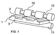
〔図1〕エンボスローラによって表面上に溝構造を設けた第1ポリマーフィルムの構造化を示す図である。 FIG. 1 is a diagram showing the structuring of a first polymer film in which a groove structure is provided on the surface by an embossing roller.
〔図2〕両側に溝構造を取り入れた第1ポリマーフィルムを示す図である。 FIG. 2 is a view showing a first polymer film incorporating a groove structure on both sides.
〔図3a〕構造化フィルムと第2の滑らかなフィルムからポリマーフィルムコンポジットを製造することを示す斜視図である。 FIG. 3a is a perspective view showing the production of a polymer film composite from a structured film and a second smooth film.
〔図3b〕両面を構造化したフィルムと2つの非構造化フィルムからポリマーフィルムコンポジットを製造することを示す斜視図である。 FIG. 3b is a perspective view showing the production of a polymer film composite from a film structured on both sides and two unstructured films.
〔図3c〕第1構造化フィルムと第2の同様に構造化したフィルムからポリマーフィルムコンポジットを製造することを示す斜視図である。 FIG. 3c is a perspective view showing the production of a polymer film composite from a first structured film and a second similarly structured film.
〔図3d〕2つの一方のみ構造化したフィルムと第3の非構造化フィルムからポリマーフィルムコンポジットを製造することを示す斜視図である。 FIG. 3d is a perspective view showing the production of a polymer film composite from two only one structured film and a third unstructured film.
〔図4a〜4g〕ポリマーフィルム内を構造化することによって形成される高さのある外形の各種形状を示す図である。 [FIGS. 4a to 4g] FIGS. 4A to 4G are views showing various shapes of a height formed by structuring the inside of a polymer film.
〔図5〕2つのポリカーボネートフィルムから成る本発明によるフェロエレクトレット多層コンポジットの拡大顕微鏡写真である。 FIG. 5 is an enlarged photomicrograph of a ferroelectret multilayer composite according to the present invention comprising two polycarbonate films.
図1は、エンボスローラ10によって、表面上に溝構造を設けた第1ポリマーフィルム1の構造化を模式的に示す。「エンボスローラ10」という用語によって、ローラはエンボスツールとして、その構造をポリマーフィルム上へ転写することができるものと理解される。たとえば、ポリマーフィルム1は、押出し直後に、エンボスローラ10と非構造化ガイドローラ11間に案内されてもよい。場合によっては、使用される装置内ではエンボスローラ10用の対向部品のために、ガイドローラ11に代えて非構造化プレートを用いることもできる。エンボスローラ10上の窪み12によって、相応に高さのある外形がポリマーフィルム1上に形成され得る。窪みによって、チャネルタイプの構造がポリマーフィルム上に形成され、これによって高さのある外形がバー2によって形成され、水平な基礎表面3上に、互いに平行で互いに分離されて配置され得る。構造化の示す形状は、本発明によれば、場合に従って適切な形状のダイを備えるスリットダイ押出しによっても得られ得る。使用されるエンボスローラは、好都合にも、形成されるべき所望の空隙形状に適切に合わせることができれば、他のエンボス構造を有してもよい。この構成では、ポリマーフィルム1の基礎表面3は、高さのある外形の反対側表面上に、ポリマーフィルム1の非構造化第2表面を形成する。示される態様の場合には、バー2は垂直な側面と水平なエッジで構成される。このような構造化ポリマーフィルム1を、本発明によれば、たとえば、図3aに示されるように、非構造化ポリマーフィルム5と接着して、長方形の断面を有するチャネルタイプの空隙4を形成することができる。溝構造は、示される実施の形態に限定されず、たとえば、窪みは半円状の断面を有するように形成されてもよい。但し、原理的には、本発明によれば、最終的に形成されるポリマーフィルムコンポジットの外向き表面は構造化されない。そして、分極の前および/または後に、電極をこれらの非構造化表面上に適用することができる。
FIG. 1 schematically shows the structuring of a
図2は、両側に形成された溝のある3次元構造を有する第1ポリマーフィルム1を示しており、この構造はたとえば、2つのエンボスローラ10がポリマーフィルム1に対して互いの上に配置され(ここでは図示しない)、ポリマーフィルム1が前記ローラ間に案内されることによって、組み込まれる。エンボスローラ10はこの場合には、各場合、円筒形状に構成された構造どうしが相互係合するように配置されてもよい。場合によっては、このように両面が構造化されたポリマーフィルム1の製造をたとえば、任意に予熱され形状形成された鋳ぐるみを備える成形ツール内で、任意に加熱されたポリマーフィルムに、圧力を印加することで変形させることによって、行うことができる。この場合のポリマーフィルム1では、ポリマーフィルム1の基礎表面3上には、図1に示されるような高さのある外形は配備されず、ポリマーフィルム1は全体的に3次元的に変形する。次に、図3bに示されるように、ポリマーフィルム1と非構造化フィルムとを、各場合、ポリマーフィルム1の両側表面上に両面から接着することによって、空隙4を形成することができる。本発明によれば、基礎表面3から出発して、高さのある外形を両面に形成するようにして、ポリマーフィルム1の両面に構造を作成することもできる。
FIG. 2 shows a
図3aは、図1と同様に製造された構造化ポリマーフィルム1と、第2の非構造化ポリマーフィルム5からの、本発明によるポリマーフィルムコンポジットの製造を模式的に示す。第2ポリマーフィルム5をポリマーフィルム1の表面上に配置することができ、ポリマーフィルム1上にはたとえば、高さのある外形がバー2の形態で形成されている。そこから形成される空隙4は、示される実施の形態では、長方形の断面を有し得る。2つのポリマーフィルム1および5の接着は、この場合には、ラミネート、粘着性接着、クリップ留め、クランプ締め、ネジ留め、リベット留めまたは溶接(たとえば、レーザ溶接、超音波溶接または振動溶接)により、行われもよい。
FIG. 3a schematically shows the production of a polymer film composite according to the invention from a structured
図3bは、図2に示される両面が構造化されたポリマーフィルム1と、2つの非構造化ポリマーフィルム5および5’からの、本発明によるポリマーフィルムコンポジットの製造を模式的に示す。非構造化ポリマーフィルム5および5’と構造化ポリマーフィルム1とを、表面側の矢印の方向に接着すると、各場合粘着性接着によって、空隙4および4’のラミネーションを形成することができる。示される実施の形態では、各場合、長方形の断面を有し得る。本発明によれば、空隙4および4’は原理的には、各場合、互いに独立して様々な形状および寸法に構成されてもよい。これは、作成されるポリマーフィルムコンポジットのラミネーション内の空隙4および4’でも保持される。本発明による空隙のラミネーションは、2つの独立したポリマーフィルム間に形成されるものであると理解され示される。形成されたポリマーフィルムコンポジット内の空隙によって、好都合にも、厚さ(すなわちポリマーフィルム1、5、5’の層方向に垂直)に伴って、より柔軟になるフェロエレクトレット多層コンポジットを製造することができ、したがって、その弾性係数を低減し、得られた空隙の分極処理を可能にすることができる。2つのポリマーフィルム1および5の接着は、この場合には、ラミネート、粘着性接着、クリップ留め、クランプ締め、ネジ留め、リベット留めまたは溶接(たとえば、レーザ溶接、超音波溶接または振動溶接)により、行われもよい。原理的には、分極は、ポリマーフィルムの接着後に、たとえば、既に設置されている電極に電圧を印加することにより直接帯電させることによって、行われてもよい。電極の設置前なら、空隙の反対側の分極を、たとえば、コロナ放電またはプラズマ法により実施することができる。
FIG. 3b schematically shows the production of a polymer film composite according to the invention from the double-sided
図3cは、図1と同様に製造された構造化ポリマーフィルム1と、第2の同様に構造化されたポリマーフィルム1’とからの、本発明によるポリマーフィルムコンポジットの製造を模式的に示す。ポリマーフィルム1および1’は共に、高さのある外形のために、基礎表面3上にバー2を有する。ポリマーフィルム1および1’は各場合、形成されたバーを有するその構造化表面側どうしを接着してもよい。この場合にはバー2は矢印の方向に正確に取り付けられるように互いの上に配置され、これによって長方形の断面を有するチャネルタイプの空隙4が、ポリマーフィルム1および1’の層方向に垂直に生じ得る。2つのポリマーフィルム1および1’の接着は、この場合には、ラミネート、粘着性接着、クリップ留め、クランプ締め、ネジ留め、リベット留めまたは溶接(たとえば、レーザ溶接、超音波溶接または振動溶接)により、行われもよい。
FIG. 3c schematically shows the production of a polymer film composite according to the invention from a structured
図3dは、図1と同様に製造された構造化ポリマーフィルム1と、第2の同様に構造化されたポリマーフィルム1’と、さらに非構造化ポリマーフィルム5とからの、本発明によるポリマーフィルムコンポジットの製造を模式的に示す。本発明によれば、示されるように、第2の構造化ポリマーフィルム1’のその非構造化表面を、ポリマーフィルム1の構造化表面側上に、矢印の方向に配置し、これをポリマーフィルム5に接着することができる。ポリマーフィルム1’とさらにポリマーフィルム5との接着によって、次に第2の空隙ラミネーションが形成され得る。示される実施の形態では、構造化フィルム1および1’は、その構造を同じ向きにして互いの上に配置され、その後互いに接着される。同様に構造は異なる向きであってもよい。たとえば、構造がバーの場合には、バーを互いに対して45°または90°の角度で配置し、これによって本発明によれば、互いに関して構造の角度または向きを違えて、全てを配置することができる。ポリマーフィルム1および1’の層順序については、1以上の構造化および/または非構造化ポリマーフィルムを様々に連続させて、様々に実施してもよい。好都合にも、空隙を有するいくつかのラミネーションを備えるフェロエレクトレット多層コンポジットの製造は、それ故様々な様式が可能であり、任意に半製品として実存のポリマーフィルムに採用されてもよく、または意図する用途および所望の特性、たとえば、弾性係数および圧電定数に適合させてもよい。
FIG. 3d shows a polymer film according to the invention from a structured
図4a〜4gは、ポリマーフィルム1内のエンボス構造の様々な実施の形態の上方図、すなわち、ポリマーフィルム1の層方向に対して右の角度での対応する空隙の基礎表面の可能な構造を示す。構造はたとえば、ポリマーフィルム1へと、エンボス加工によって、原理的にはポジ型またはネガ型形状に、すなわち凹凸として組み込まれる。示される構造の実施の形態および構成は単なる例を示し、本発明をいずれかの形態に制限することを意図するものではない。明瞭化のために、図4a〜4gでは各場合、形状の1つの窪みのみを例示的に参照の代表とする。
4a to 4g are top views of various embodiments of the embossed structure in the
図4aは凹部6を有する構造化ポリマーフィルム1を示し、凹部は円形の基礎表面を有する。凹部6は図4aに示されるように、さらに複数の小さい凹部6が形成されてもよい。
FIG. 4a shows a
図4bは凹部6を有する構造化ポリマーフィルム1を示し、凹部6は細長い長方形の基礎表面を有する。
FIG. 4 b shows a
図4cは凹部6を有する構造化ポリマーフィルム1を示し、凹部6は十字型の基礎表面を有する。
FIG. 4 c shows the structured
図4dは各種凹部6、6’を有する構造化ポリマーフィルムを示し、凹部は円形の基礎表面6の部分と菱形の基礎表面6’の部分とを有する。図4dは、円形6と菱形6’の断面を有する凹部が均一に分布した配置の場合には、好都合にも、全空隙容積を特に大きくすることができることを示している。
FIG. 4d shows a structured polymer film with
図4eは凹部6を有するポリマーフィルム1を示し、凹部6はハニカム型の基礎表面を有する。図4eは、もっぱらハニカム型断面を有する凹部6に基づく配置によって、同様に好都合にも、全空隙容積を大きくすることができることを示している。
FIG. 4e shows a
図4fは凹部6、6’、6”を有する構造化ポリマーフィルム1を示し、この構造は異なる形状および寸法で形成され、十字型6’、6”と実質的にハニカム型表面6を有する。さらに図4fは、凹部6、6’、6”は不均一に分布するように、かつ部分的に互いに接続するように形成されてもよいことを示している。
FIG. 4 f shows a
図4gは凹部6を有するポリマーフィルム1を示し、凹部6は、異なるドット厚さおよびライン厚さの異なる構造、特に六角形/ハニカム型、十字型およびドットを組み合わせて適用することによって形成される。図4gはさらに、本発明による製造処理の終了後に、連続的ポリマー層との接触で、1以上の封止された空隙が得られるように、連続的なポリマー層の縁取り領域が、構造を取り囲むように形成されてもよいことを示している。このようにして凝集型の空隙を形成することができる。さらに図4gは、本発明の範囲内では、「高さのある外形を有する構造化ポリマーフィルム1」という表現によって、ポリマーフィルムが1のみの凹部6を有するものと理解されてもよく、この場合には凹部6はいくつかの凹部の融合または結合と理解されてもよい、といったことを示している。
FIG. 4g shows a
図5は、2つのポリカーボネートフィルムから成る本発明によるフェロエレクトレット多層コンポジットの断面の拡大顕微鏡写真を示す。構造化ポリマーフィルム1は厚さ75μmのポリカーボネートフィルム(マクロホール・ベイヤー・マテリアル・サイエンスAG)であり、これを本目的のために、ちょうどガラス転移温度未満の130〜140℃に加熱した。この後、ポリカーボネートフィルム1を、溝の外形を有する成形ツール上に250barの空気圧でプレスした。成形ツールによって、ポリカーボネートフィルム1は変形して、半円筒形状の凹部を形成した。この場合には、ポリマーフィルム1の反対表面上に、相応の構造が、半円筒形状の高さのある外形として形成された。構造によって凹部を備えた構造化ポリカーボネートフィルム1のその表面側上に、75μmの厚さの滑らかなポリカーボネートフィルム5を配置し、第1フィルムにラミネートによって接着した。この手段によって、ポリマーフィルム1および5の層方向に垂直に半円状の断面を有する空隙が生じた。断面では、空隙4は100μmの高さを有していた。盛り上がりのあるポリマーフィルム1の緻密質の外側表面と、さらにはポリマーフィルム5の外向きの非構造化表面に、次に各場合、50nmの厚さのアルミニウム電極を設けた。内側空隙4の分極を、直接電圧を印加することによって行った。作成したコンポジットは、実施例5に従って得られた試験片の圧電活性に比べて、良好な圧電活性を示した。
FIG. 5 shows an enlarged micrograph of a cross section of a ferroelectret multilayer composite according to the invention consisting of two polycarbonate films. The structured
本発明を以下に記載する実施例によってさらに説明するが、これに限定されない。 The invention is further illustrated by the examples described below, but is not limited thereto.
(実施例1)
潤滑添加剤マスターバッチの製造
常套の二軸混練押出し成形機(たとえば、ZSK 32)を用いた、250℃〜330℃のポリカーボネートにとって一般的処理温度での、潤滑添加剤化合物の製造。
Example 1
Production of lubricant additive masterbatch Production of lubricant additive compounds using conventional twin screw kneader extruders (eg ZSK 32) at processing temperatures typical for polycarbonates between 250 ° C and 330 ° C.
以下の組成を有するマスターバッチを:
・ベイヤー・マテリアル・サイエンスAGによって製造されたポリカーボネート、マクローロン(Makrolon)2600 000000を、98重量%の割合で、
・ジ−イソプロピルジメチルアンモニウムパーフルオロブタンスルホネートを、無色のパウダーとして、2重量%の割合で、
製造した。
A masterbatch having the following composition:
• Polycarbonate manufactured by Bayer MaterialScience AG, Makrolon 2600 000000, in a proportion of 98% by weight,
Di-isopropyldimethylammonium perfluorobutane sulfonate as a colorless powder in a proportion of 2% by weight,
Manufactured.
(実施例2)
(フィルム押出し)
以下の組成の化合物を:
・実施例1による潤滑添加剤マスターバッチを20重量%の割合で、およびベイヤー・マテリアル・サイエンスAGによって製造されたポリカーボネート、マクローロン2600
を80.0重量%の割合で、
混合した。
(Example 2)
(Film extrusion)
A compound of the following composition:
• Polycarbonate, Macrolon 2600, manufactured by Bayer Material Science AG with 20% by weight of the lubricant additive masterbatch according to Example 1
At a ratio of 80.0% by weight,
Mixed.
フィルムの製造に使用される設備は、
・105mmの直径(D)と41×Dの長さのスクリューを備えるメイン押出し成形機;スクリューは脱気ゾーンを有する;
・1500mm幅の押出しスリットダイ;
・水平なローラ配置を有する3−ローラスムージングカレンダ、第3ローラは水平に関して+/−45°で旋回することができる;
・ローラトラック;
・保護フィルムを両面塗布するための装置;
・取出し装置;
・巻上げステーション
から成る。
The equipment used for film production is
A main extruder with a 105 mm diameter (D) and a 41 × D length screw; the screw has a degassing zone;
-1500 mm wide extrusion slit die;
A 3-roller smoothing calendar with a horizontal roller arrangement, the third roller can swivel +/− 45 ° with respect to the horizontal;
・ Roller track;
-Equipment for applying protective films on both sides;
・ Removal device;
-Consists of a winding station.
粒剤を押出し成形機の充填ファンネルに投入した。押出し成形機の可塑化システムのシリンダ/スクリューで、材料の溶融と運搬を行った。材料溶融物をスムージングカレンダに投入し、そのローラの温度を表1に記載した。(3つのローラから成る)スムージングカレンダで、フィルムを規定の形状にし、冷却を行った。 The granules were put into the filling funnel of the extrusion molding machine. The material was melted and transported by the cylinder / screw of the plasticizing system of the extruder. The material melt was charged into a smoothing calendar and the temperature of the roller is listed in Table 1. A smoothing calendar (consisting of 3 rollers) was used to cool the film to a defined shape.

フィルム表面の一方側を構造化する目的のために、この場合には、使用される設備において、ゴムローラを第1の位置で使用した。フィルム表面の構造化用に使用されるゴムローラは、ナウタ・ロール社(Nauta Roll Corporation)が持つ特許第US4,368,240号公報に開示される。 For the purpose of structuring one side of the film surface, in this case a rubber roller was used in the first position in the equipment used. A rubber roller used for structuring the film surface is disclosed in US Pat. No. 4,368,240 owned by Nauta Roll Corporation.
設備の第2の位置には、高度複合放物集光器(advanced−compound−parabolic concentrator)(ACPC)構造を用いて構造化された金属ローラを使用した。以下のパラメータ:受光角8°、短縮係数:0.05を有するACPC構造を使用した。 In the second position of the facility, a metal roller structured with an advanced-compound-parabolic concentrator (ACPC) structure was used. An ACPC structure with the following parameters: acceptance angle 8 °, shortening factor: 0.05 was used.
構造の複合放物集光器(CPC)領域を:
a)規定受光角によるフレネル方程式からの媒体の開口角θ1とθ2とを計算;
b)以下の方程式
による、媒体の開口角がθ1であるパラボラブランチ(parabola branch)P1の構築および媒体の開口角がθ2であるパラボラブランチP2の2つのパラボラブランチの構築;
c)パラボラブランチのエンドポイント(end−point)F1、F2およびE1、E2の計算;
d)媒体の開口角−θ1およびθ2周りのパラボラの回転およびパラボラP2のX軸に沿う並進;
e)任意に、θ1≠θ2の非対称変形の場合、ポイントE1とE2とによって規定される傾斜面の傾斜の決定;
f)工程a)〜e)において構築されるジオメトリーからの大気中における有効受光角の決定;
g)有効受光角と規定受光角との比較、ずれが0.001%よりも大きい場合、工程a)において規定受光角の代わりに修正受光角を用いた、工程a)〜f)の繰り返しであって、修正受光角が規定受光角と同じでなく、工程f)の有効受光角が規定受光角と一致するように修正受光角が選択される、工程a)〜f)の繰り返し;並びに
h)有効受光角の規定受光角からのずれ0.001%以下を達成すると、パラボラのy方向を短縮係数によって規定される程度に短縮すること;
によって決定することができた。
The compound parabolic concentrator (CPC) region of the structure:
a) calculating the aperture angles θ 1 and θ 2 of the medium from the Fresnel equation with the specified acceptance angle;
b) The following equation
In accordance the construction of the two parabola branches of the parabola branch P 2 is a second opening angle of the parabola branches (parabola branch) P 1 Construction and media theta is one opening angle of the medium theta;
c) calculation of the end-points F 1 , F 2 and E 1 , E 2 of the parabolic branch;
d) rotation of the parabola around the aperture angles of the medium −θ 1 and θ 2 and translation of the parabola P 2 along the X axis;
e) Optionally, in the case of an asymmetric deformation of θ1 ≠ θ2, determining the slope of the slope defined by points E 1 and E 2 ;
f) determination of the effective acceptance angle in the atmosphere from the geometry constructed in steps a) to e);
g) Comparison between the effective light receiving angle and the specified light receiving angle, and if the deviation is greater than 0.001%, repeat steps a) to f) using the modified light receiving angle instead of the specified light receiving angle in step a). The corrected light receiving angle is not the same as the specified light receiving angle, and the corrected light receiving angle is selected such that the effective light receiving angle in step f) matches the specified light receiving angle; and repetition of steps a) to f); and h ) When the deviation of the effective light receiving angle from the specified light receiving angle is 0.001% or less, the parabola y direction is shortened to the extent specified by the shortening factor;
Could be determined by.
上に示す構造の記載は非常に一般性を維持したものであるので、ACPC構造を有するローラは原理的には、様々な材料から製造されてもよい(媒体1:たとえば、PMMAまたはポリカーボネート)。さらに、ACPC領域を様々な環境で使用してもよい(媒体2:たとえば、空気または水)。すなわち、媒体1および媒体2のその屈折率を次に定められたフレネル方程式に代入する。
Since the description of the structure shown above is very general, a roller with an ACPC structure may in principle be manufactured from a variety of materials (media 1: eg PMMA or polycarbonate). Furthermore, the ACPC region may be used in various environments (medium 2: air or water, for example). That is, the refractive indexes of the
次にエンボス加工されたフィルムを取出し装置によって搬送した。この後、ポリエチレンから成る保護フィルムを両側に塗布し、フィルムの巻上げを行うことができた。ベース層が180μmの厚さを有するフィルムを得、その一方側上にACPC構造をエンボス加工し、他方側上に8μmの粗面度R3zの深さを有するテクスチャーを加工した。ベース層からのACPC構造の高さは73μmであり、間隔は135μmであった。言い換えれば、谷から谷まで135μmの間隔であり、谷からピーク頂点までは垂直に73μmの間隔である。 Next, the embossed film was taken out and conveyed by an apparatus. Thereafter, a protective film made of polyethylene was applied to both sides, and the film could be wound up. A film having a base layer thickness of 180 μm was obtained, an ACPC structure was embossed on one side, and a texture having a roughness R 3 z depth of 8 μm was processed on the other side. The height of the ACPC structure from the base layer was 73 μm and the spacing was 135 μm. In other words, the interval from the valley to the valley is 135 μm, and the interval from the valley to the peak apex is 73 μm vertically.
(実施例3)
ローラによって構造化された第1フィルムと、20μmの厚さを有する滑らかなポリカーボネートフィルムとからのフェロエレクトレット多層コンポジットの製造:
滑らかな20μmの厚さのポリカーボネートフィルムを、実施例1に記載されるような、ACPCローラの外形を備え、285μmの厚さを有するポリカーボネートフィルムの構造化された側上に配置した。次に、このフィルムコンポジットを205℃でラミネートした。ラミネート後、フィルムコンポジットは285μmの層厚を有する。ローラの外形がフィルムの深さの外形になり、2つのポリカーボネートフィルムのポリマーフィルムコンポジット内に空隙が形成される。断面では、これらの空隙は40μmの高さと25μmの幅を有する。空隙の間隔はエンボス加工ローラの外形によって予め定められる。しかし、ラミネート処理のために、ローラの外形は幾分平坦化されるので、空隙は当初のローラの外形の予め定められた高さより小さくなる。その結果、層スタック全体の厚さは、ラミネート処理前の個々のフィルムの層厚の合計より小さくなる。次に、フィルムコンポジットの両側表面上に、50nmの厚さのアルミニウム電極を設けた。内側空隙の分極は、17kV〜19kVの電圧を直接印加することによって行った。分極後、圧電効果を直接測定した。17kVでの分極の場合には、測定により、分極直後に4pC/Nのd33係数を得、19kVでの分極の場合には、5pC/Nのd33係数を得た。各試験片について5回の測定を行い、平均値を作成した。
(Example 3)
Production of a ferroelectret multilayer composite from a first film structured by a roller and a smooth polycarbonate film having a thickness of 20 μm:
A smooth 20 μm thick polycarbonate film was placed on the structured side of a polycarbonate film with an ACPC roller profile as described in Example 1 and having a thickness of 285 μm. Next, this film composite was laminated at 205 ° C. After lamination, the film composite has a layer thickness of 285 μm. The outer shape of the roller becomes the outer shape of the depth of the film, and voids are formed in the polymer film composite of the two polycarbonate films. In cross section, these voids have a height of 40 μm and a width of 25 μm. The gap interval is predetermined by the outer shape of the embossing roller. However, because of the laminating process, the outer shape of the roller is somewhat flattened so that the air gap is smaller than a predetermined height of the original roller shape. As a result, the total thickness of the layer stack is less than the sum of the individual layer thicknesses before the lamination process. Next, aluminum electrodes having a thickness of 50 nm were provided on both surfaces of the film composite. The polarization of the inner gap was performed by directly applying a voltage of 17 kV to 19 kV. After polarization, the piezoelectric effect was measured directly. In the case of polarization at 17 kV, the measurement gave a d33 coefficient of 4 pC / N immediately after the polarization, and in the case of polarization at 19 kV, a d33 coefficient of 5 pC / N was obtained. Each test piece was measured five times to create an average value.
(実施例4)
ローラ外形を有するポリカーボネートフィルムと、50μmの厚さの滑らかなポリカーボネートフィルムとからのフェロエレクトレット多層コンポジットの製造:
滑らかな50μmの厚さのポリカーボネートフィルムを、実施例1と同様のローラの外形を備え、285μmの全体厚さを有するフィルムの外形形成された側上に配置した。次に、このフィルムコンポジットを205℃でラミネートした。ラミネート後、フィルムコンポジットは320μmの厚さを有する。ローラの外形がフィルムの深さの外形になり、ポリマーフィルムスタック内に三角形の空隙が形成される。これらの空隙は約40μmの深さと60μmの幅を有する。空隙の間隔はエンボス加工ローラの外形によって予め定められる。ラミネート処理のために、50μmの厚さのポリカーボネート層はローラ外形内にプレスされるので、空隙は当初のローラの外形の予め定められた高さより小さくなる。その結果、ポリマーフィルムコンポジット全体の厚さは、ラミネート処理前の個々のフィルムの層厚の合計より小さくなる。次に、フィルムコンポジットの両側表面上に、50nmの厚さのアルミニウム電極を設けた。内側空隙の分極は、20kVの電圧を直接印加することによって行った。分極後、圧電効果を直接測定した。この実施例によれば、4cm×4cmの大きさの4つの試験片を作成し、それぞれ5回評価した。分極直後の測定値について平均値を得、これを表2に示す。
(Example 4)
Production of a ferroelectret multilayer composite from a polycarbonate film having a roller profile and a smooth polycarbonate film of 50 μm thickness:
A smooth 50 μm thick polycarbonate film was placed on the contoured side of the film with the same roller profile as in Example 1 and an overall thickness of 285 μm. Next, this film composite was laminated at 205 ° C. After lamination, the film composite has a thickness of 320 μm. The outer shape of the roller becomes the outer shape of the film depth, and triangular voids are formed in the polymer film stack. These voids have a depth of about 40 μm and a width of 60 μm. The gap interval is predetermined by the outer shape of the embossing roller. Due to the laminating process, a 50 μm thick polycarbonate layer is pressed into the roller profile, so that the gap is smaller than a predetermined height of the original roller profile. As a result, the total thickness of the polymer film composite is less than the sum of the individual film layer thicknesses before lamination. Next, aluminum electrodes having a thickness of 50 nm were provided on both surfaces of the film composite. The polarization of the inner gap was performed by directly applying a voltage of 20 kV. After polarization, the piezoelectric effect was measured directly. According to this example, four test pieces each having a size of 4 cm × 4 cm were prepared and evaluated each time five times. Average values were obtained for the measured values immediately after polarization, and are shown in Table 2.
(実施例5)
エンボスローラによって構造化された2つのポリカーボネートフィルムからのフェロエレクトレット多層コンポジットの製造:
各場合、全体(基礎表面と構造)で285μmの厚さを有し、ローラの外形を備える2つのフィルムの外形形成された側を、エンボス構造が交差するように、互いの上に配置した。次に、このフィルムコンポジットを205℃でラミネートした。ラミネート後、フィルムコンポジットは550μmの層厚を有する。ローラの外形がフィルムの深さの外形になり、層スタック内に空隙が形成される。空隙は交差構造に関して45°と評価され、断面では、これらの空隙は約50μmの高さと100μmの幅を有する。空隙の間隔は、45°と評価されるので、190μmに相当する。ラミネート処理のために、ローラの外形は平坦化されたので、空隙の寸法は当初のローラの外形の予め定められた高さより小さくなった。その結果、層スタック全体の厚さは、ラミネート処理前の個々のフィルムの層厚の合計より小さくなった。次に、フィルムコンポジットの外向きの両側表面上に、50nmの厚さのアルミニウム電極を設けた。内側の空隙の分極は、20kVの電圧を直接印加することによって行った。分極直接、圧電効果を測定した。この実施例によれば、4cm×4cmの大きさの9個の試験片を作成し、評価した。各場合、圧電定数の測定を5回行い、そこから平均値を作成した。分極直後の測定値についての値を得、これを表3に示す。
(Example 5)
Production of ferroelectret multilayer composite from two polycarbonate films structured by embossing rollers:
In each case, the contoured sides of the two films with a total thickness (base surface and structure) of 285 μm and comprising the contour of the roller were placed on top of each other so that the embossed structure intersected. Next, this film composite was laminated at 205 ° C. After lamination, the film composite has a layer thickness of 550 μm. The outer shape of the roller becomes the outer shape of the depth of the film, and voids are formed in the layer stack. The voids are evaluated at 45 ° with respect to the crossing structure, and in the cross section, these voids have a height of about 50 μm and a width of 100 μm. Since the gap interval is estimated to be 45 °, it corresponds to 190 μm. Because of the laminating process, the roller profile was flattened so that the size of the gap was less than the predetermined height of the original roller profile. As a result, the total thickness of the layer stack was less than the sum of the individual layer thicknesses before lamination. Next, an aluminum electrode having a thickness of 50 nm was provided on both outward facing surfaces of the film composite. The polarization of the inner gap was performed by directly applying a voltage of 20 kV. The direct polarization and piezoelectric effect was measured. According to this example, nine test pieces having a size of 4 cm × 4 cm were prepared and evaluated. In each case, the piezoelectric constant was measured five times, and an average value was created therefrom. Values for the measured values immediately after polarization were obtained and are shown in Table 3.
(実施例6)
成形ツール内で圧力を印加することによって構造化された第1フィルムと、滑らかなポリカーボネートフィルムからのフェロエレクトレット多層コンポジットの製造:
75μmの厚さを有するポリカーボネートフィルム(マクロホール・ベイヤー・マテリアル・サイエンスAG)を、ちょうどガラス転移温度未満の130〜140℃に加熱した。この後、ポリカーボネートフィルムを、250barの空気圧を用いて、溝型外形を有する成形ツール上にプレスした。ポリカーボネートフィルムは、それ自体がツールの鋳ぐるみに適合して、永久的に溝型に変形した。この場合には、フィルムはその全体が変形するので、高さのある外形は一方表面上に生じ、対応する溝型凹部はポリカーボネートの他方表面側上に生じた。この構造化ポリカーボネートフィルム上に、滑らかな75μmの厚さのポリカーボネートフィルムを配置し、構造化ポリカーボネートフィルムにラミネートによって接着した。空隙は、ポリマーフィルムの層方向に垂直に半円状の断面を有していた。断面では、空隙は100μmの高さを有していた。次に、フィルムコンポジットの両面上に50nmの厚さのアルミニウム電極を設けた。内側空隙の分極は、電圧を直接印加することによって行った。作成したコンポジットは、実施例5により得られた試験片の圧電活性に比べて、良好な圧電活性を示した。ポリマーフィルムコンポジットの空隙領域を詳細に拡大したものを図5に示す。
(Example 6)
Production of a ferroelectret multilayer composite from a first film structured by applying pressure in a molding tool and a smooth polycarbonate film:
A polycarbonate film (Macrohole Bayer Material Science AG) having a thickness of 75 μm was heated to 130-140 ° C., just below the glass transition temperature. After this, the polycarbonate film was pressed onto a molding tool with a grooved profile using an air pressure of 250 bar. The polycarbonate film itself adapted to the tool cast and was permanently transformed into a groove shape. In this case, since the entire film was deformed, a height profile was formed on one surface, and a corresponding groove-shaped recess was formed on the other surface side of the polycarbonate. On this structured polycarbonate film, a smooth 75 μm thick polycarbonate film was placed and adhered to the structured polycarbonate film by lamination. The voids had a semicircular cross section perpendicular to the layer direction of the polymer film. In the cross section, the voids had a height of 100 μm. Next, an aluminum electrode having a thickness of 50 nm was provided on both surfaces of the film composite. The polarization of the inner gap was performed by applying a voltage directly. The prepared composite showed better piezoelectric activity than that of the test piece obtained in Example 5. FIG. 5 shows an enlarged detail of the void region of the polymer film composite.
(実施例7)
エンボスパンチの外形を有するポリカーボネートフィルムと、滑らかな125μmの厚さのポリカーボネートフィルムから成るフェロエレクトレット多層コンポジット:
アルミニウムから成るエンボスパンチに溝構造を設けた。この関連で、溝は1mmの間隔、80μmの深さを有する。このエンボスパンチへと、ポリカーボネートフィルム(マクロホール DE 1−1、125μmの厚さ)を、ホットプレスでプレスし、溝構造を、高さのある外形の形態で、ポリカーボネートフィルム上に生じさせた。第2ポリカーボネートフィルム(マクロホール DE 1−1、125μmの厚さ)上に、Apec1800溶液(メシチレン、1メトキシ−2−プロパノールアセテート、1,2,4−トリメチルベンゼン、エチル−3−エトキシプロピオネート、クメンおよび溶媒ナフサ)をドクターブレードで塗布した。次に、溶媒が蒸発するまで、2つのフィルムを静かに互いにプレスし、このようにして互いに接着した。作成したコンポジットの外向き表面上に電極を設け、内側空隙4を分極した。ポリマーフィルムコンポジットは、実施例5により得られた試験片の圧電活性に比べて、良好な圧電活性を示した。
(Example 7)
A ferroelectret multilayer composite consisting of a polycarbonate film with an embossed punch profile and a smooth 125 μm thick polycarbonate film:
A groove structure was provided in an embossed punch made of aluminum. In this connection, the grooves have a spacing of 1 mm and a depth of 80 μm. To this embossing punch, a polycarbonate film (macro hole DE 1-1, thickness of 125 μm) was pressed with a hot press to produce a groove structure on the polycarbonate film in the form of a high profile. Apec 1800 solution (mesitylene, 1 methoxy-2-propanol acetate, 1,2,4-trimethylbenzene, ethyl-3-ethoxypropionate) on a second polycarbonate film (macrohole DE 1-1, thickness of 125 μm) , Cumene and solvent naphtha) were applied with a doctor blade. The two films were then gently pressed together until the solvent evaporated and thus adhered to each other. An electrode was provided on the outward surface of the composite prepared, and the
作成したフェロエレクトレット多層コンポジット系のd33圧電定数の機械的測定様式、および測定の実施:
測定装置について、原理的には、以下の3つの主要要素:応力発生器、応力測定装置および電荷測定装置が必要である。応力発生器には、ブルーエル&クジャー(Bruel & Kjar)によって製造された電気的振動励振器、タイプ4810を選択した。振動励振器によって、入力電圧に依存した規定の応力を出力することができる。この振動励振器を可動式プラットホームに取り付け、垂直方向におけるその位置を手動で調節することができる。振動励振器の高さの調節は、試験片をクランプするために、必要である。さらに、測定に必要な静止時予備圧力を、これによって調節することができる。振動励振器を制御するために、スタンフォード・リサーチ・システムズ(Stanford Research Systems)によって製造された関数発生器DS345を、ブルーエル&クジャーによって製造された出力増幅器、タイプ2718と共同で使用した。応力測定装置には、バースター(Burster)によって製造された応力センサー、タイプ8435を用いた。応力センサーは、0N〜200Nの範囲内での圧力測定と張力測定の両方用に設計されている。しかし、力の作用は垂直方向にしか生じ得ないので、横力と回転力はセンサーに作用しない。これを担保するために、応力センサーは円筒状の圧力案内レールを備え、ステンレススチールから成るボルトがほとんど摩擦がない状態でそこをスライドしていた。ボルトの自在端部には2センチメートル幅の研磨されたプレートが配置され、試験片表面を担持する役割を果たしていた。応力センサーからの信号を、バースターによって製造されたモジュール式増幅器、タイプ9243で記録し、オシロスコープ、GOULD 4094に送信する。
Mechanical measurement mode of d33 piezoelectric constant of the produced ferroelectret multilayer composite system, and implementation of measurement:
In principle, the measuring device requires three main elements: a stress generator, a stress measuring device and a charge measuring device. As the stress generator, an electrical vibration exciter, type 4810, manufactured by Bruel & Kjar was selected. The vibration exciter can output a specified stress depending on the input voltage. This vibration exciter can be attached to a movable platform and its position in the vertical direction can be adjusted manually. Adjustment of the height of the vibration exciter is necessary to clamp the specimen. Furthermore, the stationary pre-pressure required for the measurement can be adjusted thereby. To control the vibration exciter, a function generator DS345 manufactured by Stanford Research Systems was used in conjunction with an output amplifier, type 2718, manufactured by Blue L & Kuja. A stress sensor, type 8435, manufactured by Burster was used as the stress measuring device. The stress sensor is designed for both pressure and tension measurements in the range of 0N to 200N. However, since the action of force can only occur in the vertical direction, lateral force and rotational force do not act on the sensor. In order to ensure this, the stress sensor was provided with a cylindrical pressure guide rail, and a stainless steel bolt slid there with almost no friction. A polished plate having a width of 2 centimeters was disposed at the free end of the bolt, and served to support the surface of the test piece. The signal from the stress sensor is recorded with a modular amplifier manufactured by Burster, type 9243, and sent to an oscilloscope, GOLD 4094.
電荷測定装置には、ブルーエル&クジャーによって製造された電荷増幅器、タイプ2635を用いた。電荷増幅器によって、0.1pCまでの電荷を記録することができる。表面電荷の測定のために、試験片の両側を電荷増幅器に電気的に接続せねばならない。試験片の下側との電気的接触は、表面を担持することによって可能であり、そして構造全体に接続される。試験片の上側は、真鍮から成る加圧パンチによって電荷増幅器に接続した。パンチは、振動励振器上のプレキシガラスから成るアタッチメントによって、残りの構造からは電気的に絶縁され、ケーブルによって電荷増幅器に接続される。 The charge measuring device used was a charge amplifier type 2635 manufactured by Blue L & Kuja. Charge amplifiers can record charges up to 0.1 pC. For measurement of the surface charge, both sides of the specimen must be electrically connected to the charge amplifier. Electrical contact with the underside of the specimen is possible by carrying the surface and connected to the entire structure. The upper side of the test piece was connected to a charge amplifier by a pressure punch made of brass. The punch is electrically isolated from the rest of the structure by an attachment made of plexiglass on a vibration exciter and connected to the charge amplifier by a cable.
ケーブルは、機械的ストレスを排除し、そして測定結果の変造を排除するために、できる限り薄く柔軟であるべきである。測定信号は最終的に電荷増幅器からオシロスコープに送信される。基準として、3Nの予備圧力(静止時)を設定し、1Nの幅(動作時)で測定した。 The cable should be as thin and flexible as possible to eliminate mechanical stress and to avoid alteration of the measurement results. The measurement signal is finally transmitted from the charge amplifier to the oscilloscope. As a reference, a preliminary pressure of 3N (at rest) was set, and the measurement was performed with a width of 1N (at operation).
1 第1ポリマーフィルム、1’,5 第2ポリマーフィルム、4,4’ 空隙。 1 1st polymer film, 1 ', 5 2nd polymer film, 4, 4' gap.
Claims (11)
a)第1ポリマーフィルム(1)の少なくとも1つの第1表面を構造化し、高さのある外形を形成し、
b)工程a)で形成された第1ポリマーフィルムの構造化表面上に、少なくとも1つの第2ポリマーフィルム(5,1’)を適用し、
c)ポリマーフィルム(1,1’,5)を接着してポリマーフィルムコンポジットを生じさせ、空隙(4,4’)を形成し、
d)工程c)で形成された空隙(4,4’)の内側表面を、反対電荷を用いて帯電させること
を特徴とする製造方法。 A method for producing a ferroelectret two-layer or multilayer composite having voids, comprising the following steps:
a) structuring at least one first surface of the first polymer film (1) to form a height profile;
b) applying at least one second polymer film (5, 1 ') on the structured surface of the first polymer film formed in step a);
c) polymer film (1,1 ′, 5) is glued to form a polymer film composite, forming voids (4,4 ′);
d) A production method comprising charging the inner surface of the void (4, 4 ′) formed in step c) using an opposite charge.
Applications Claiming Priority (3)
| Application Number | Priority Date | Filing Date | Title |
|---|---|---|---|
| EP09009203A EP2286988A1 (en) | 2008-12-13 | 2009-07-15 | Ferroelectric dual and multiple layer compound and method for its manufacture |
| EP09009203.2 | 2009-07-15 | ||
| PCT/EP2009/008479 WO2010066348A2 (en) | 2008-12-13 | 2009-11-28 | Ferroelectret double and multilayer composite and method for production thereof |
Publications (3)
| Publication Number | Publication Date |
|---|---|
| JP2012532768A JP2012532768A (en) | 2012-12-20 |
| JP2012532768A5 JP2012532768A5 (en) | 2013-02-07 |
| JP5567030B2 true JP5567030B2 (en) | 2014-08-06 |
Family
ID=47528439
Family Applications (1)
| Application Number | Title | Priority Date | Filing Date |
|---|---|---|---|
| JP2011539920A Expired - Fee Related JP5567030B2 (en) | 2009-07-15 | 2009-11-28 | Ferro-electret two-layer and multilayer composite and method for producing the same |
Country Status (1)
| Country | Link |
|---|---|
| JP (1) | JP5567030B2 (en) |
Families Citing this family (2)
| Publication number | Priority date | Publication date | Assignee | Title |
|---|---|---|---|---|
| DK2376278T3 (en) * | 2008-12-13 | 2013-03-18 | Bayer Materialscience Ag | Ferroelectric Multilayer Composite Material and Process for Producing a Ferroelectric Multilayer Composite Material with Parallel Tubular Channels |
| EP2450974A1 (en) * | 2010-11-03 | 2012-05-09 | Bayer MaterialScience AG | Polymer layer structure with ferroelectric characteristics and method for producing same |
Family Cites Families (4)
| Publication number | Priority date | Publication date | Assignee | Title |
|---|---|---|---|---|
| US5702659A (en) * | 1995-11-30 | 1997-12-30 | Corning Incorporated | Honeycomb extrusion die and methods |
| KR20020076228A (en) * | 1999-09-27 | 2002-10-09 | 에스.씨. 존슨 앤드 선, 인코포레이티드 | Layered cleaning sheets |
| JP2002035520A (en) * | 2000-07-26 | 2002-02-05 | Mitsui Chemicals Inc | Filter |
| JP2008044332A (en) * | 2006-08-16 | 2008-02-28 | Yasuo Namita | Sheet material and product using the sheet |
-
2009
- 2009-11-28 JP JP2011539920A patent/JP5567030B2/en not_active Expired - Fee Related
Also Published As
| Publication number | Publication date |
|---|---|
| JP2012532768A (en) | 2012-12-20 |
Similar Documents
| Publication | Publication Date | Title |
|---|---|---|
| KR101515261B1 (en) | Ferroelectret double and multilayer composite and method for production thereof | |
| JP2011109095A (en) | Two- or multi-layer ferroelectrets and method for manufacturing the same | |
| US20140084747A1 (en) | Electromechanical converter having a two-layer base element, and process for the production of such an electromechanical converter | |
| JP2013513230A (en) | Piezoelectric polymer film element, in particular polymer foil, and method for producing the same | |
| WO2013118598A1 (en) | Piezoelectric element including fluororesin film | |
| US20140009039A1 (en) | Polymer layer composite with ferroelectret properties and method for producing said composite | |
| JP5628197B2 (en) | Ferro-electret multilayer composite and method for producing ferro-electret multilayer composite with parallel tubular channels | |
| TW202137591A (en) | Laminated piezoelectric element | |
| JP5567030B2 (en) | Ferro-electret two-layer and multilayer composite and method for producing the same | |
| US9832572B2 (en) | Electroactive sound transducer foil having a structured surface | |
| EP4277299A1 (en) | Piezoelectric film | |
| WO2023047958A1 (en) | Multilayer piezoelectric element and electroacoustic transducer | |
| EP2439000A1 (en) | Polymer layer composite with ferroelectric characteristics and method for producing same |
Legal Events
| Date | Code | Title | Description |
|---|---|---|---|
| A521 | Request for written amendment filed |
Free format text: JAPANESE INTERMEDIATE CODE: A523 Effective date: 20121023 |
|
| A621 | Written request for application examination |
Free format text: JAPANESE INTERMEDIATE CODE: A621 Effective date: 20121023 |
|
| A977 | Report on retrieval |
Free format text: JAPANESE INTERMEDIATE CODE: A971007 Effective date: 20130529 |
|
| A131 | Notification of reasons for refusal |
Free format text: JAPANESE INTERMEDIATE CODE: A131 Effective date: 20130618 |
|
| A601 | Written request for extension of time |
Free format text: JAPANESE INTERMEDIATE CODE: A601 Effective date: 20130917 |
|
| A602 | Written permission of extension of time |
Free format text: JAPANESE INTERMEDIATE CODE: A602 Effective date: 20130925 |
|
| A601 | Written request for extension of time |
Free format text: JAPANESE INTERMEDIATE CODE: A601 Effective date: 20131017 |
|
| A602 | Written permission of extension of time |
Free format text: JAPANESE INTERMEDIATE CODE: A602 Effective date: 20131024 |
|
| A601 | Written request for extension of time |
Free format text: JAPANESE INTERMEDIATE CODE: A601 Effective date: 20131115 |
|
| A602 | Written permission of extension of time |
Free format text: JAPANESE INTERMEDIATE CODE: A602 Effective date: 20131122 |
|
| RD04 | Notification of resignation of power of attorney |
Free format text: JAPANESE INTERMEDIATE CODE: A7424 Effective date: 20131219 |
|
| TRDD | Decision of grant or rejection written | ||
| A01 | Written decision to grant a patent or to grant a registration (utility model) |
Free format text: JAPANESE INTERMEDIATE CODE: A01 Effective date: 20140520 |
|
| A61 | First payment of annual fees (during grant procedure) |
Free format text: JAPANESE INTERMEDIATE CODE: A61 Effective date: 20140618 |
|
| R150 | Certificate of patent or registration of utility model |
Ref document number: 5567030 Country of ref document: JP Free format text: JAPANESE INTERMEDIATE CODE: R150 |
|
| LAPS | Cancellation because of no payment of annual fees |