JP5565965B2 - Gas stove - Google Patents
Gas stove Download PDFInfo
- Publication number
- JP5565965B2 JP5565965B2 JP2011012224A JP2011012224A JP5565965B2 JP 5565965 B2 JP5565965 B2 JP 5565965B2 JP 2011012224 A JP2011012224 A JP 2011012224A JP 2011012224 A JP2011012224 A JP 2011012224A JP 5565965 B2 JP5565965 B2 JP 5565965B2
- Authority
- JP
- Japan
- Prior art keywords
- gas stove
- heat insulating
- lower body
- insulating member
- upper body
- Prior art date
- Legal status (The legal status is an assumption and is not a legal conclusion. Google has not performed a legal analysis and makes no representation as to the accuracy of the status listed.)
- Expired - Fee Related
Links
Images


Landscapes
- Baking, Grill, Roasting (AREA)
Description
本発明は、ガスコンロに関し、例えばコンロ本体の厚さを薄く形成したガスコンロに関する。 The present invention relates to a gas stove, for example, a gas stove in which the thickness of a stove body is thin.
従来、加熱調理等に用いられるガスコンロとして、多様な形状のものが開発されており、例えば、移動、収納の容易性やデザイン性の向上を図るためにコンロ本体の厚さを薄く形成することがある。しかしながら、このようにコンロ本体を薄型に形成すると、ガスコンロに載置された調理器具やガスコンロのバーナからガスコンロの上面又は底面までの距離が短くなるため、ガスコンロの上面、底面あるいは内部が加熱されすぎる虞ある。そして、ガスコンロが加熱されすぎると、ガスコンロを載置される台の温度上昇や、内部あるいは外部に設けられた電池や基板等の部品の温度上昇による不具合が発生する虞がある。 Conventionally, various types of gas stoves used for cooking, etc. have been developed. For example, the thickness of the stove body can be made thin in order to improve the ease of movement and storage and the design. is there. However, if the stove body is formed thin in this way, the distance from the cooking utensil placed on the gas stove or the burner of the gas stove to the top or bottom surface of the gas stove becomes short, so the top, bottom or inside of the gas stove is heated too much There is a fear. If the gas stove is heated too much, there is a possibility that a malfunction may occur due to a temperature rise of a table on which the gas stove is placed or a temperature rise of components such as a battery and a board provided inside or outside.
そこで、例えば特許文献1に示されるように、ガスコンロの本体となる筐体の内側に円筒状バーナ本体の外周面にのみ炎孔を有するバーナを装着するとともに、バーナの下部周面に、火炎から下方への輻射熱を遮断する金属製フランジ板を取り付けたものが知られている。確かに、このようなガスコンロによれば、下方への輻射熱をフランジ板によってある程度遮断することができるとも考えられる。
Therefore, for example, as shown in
しかしながら、特許文献1に記載されたガスコンロは、輻射熱を受けて加熱されるフランジ板がコンロ本体の内側に配置されているため、これによって、ガスコンロの内部が加熱されてしまう虞がある。また、コンロ本体の内側にフランジ板を配置するためのスペースが必要であり、このスペース確保のために、一定以上の薄型化が困難となる。また、下方への輻射熱の対策としてフランジ板が設けられているのみであるため、ガスコンロの上面の加熱を抑制することができず、ガスコンロの上面が加熱される虞がある。
However, in the gas stove described in
そこで、本発明は、上記のような課題の少なくとも一つを解決することにより、従来に比しコンロ本体等の温度上昇を抑制したガスコンロを提供することを目的とする。 Then, this invention aims at providing the gas stove which suppressed the temperature rise of a stove main body etc. compared with the past by solving at least one of the above subjects.
このような課題を解決するため、本発明によるガスコンロは、コンロ本体内にバーナが収容されたガスコンロであって、前記コンロ本体は、前記バーナが固定される下部体と該下部体の上方に位置する上部体とからなり、前記下部体及び上部体は樹脂製の断熱部材を介して接合されており、前記上部体の外周縁の一部を切り欠くとともに、前記断熱部材の一部を上方に露出する切欠部と、前記切欠部から上方に露出する断熱部材の上面にスライド自在に設けられた前記バーナの操作部と、を備えていることを特徴とする。
また、前記上部体、下部体及び断熱部材は、樹脂製の固定手段によって接合されていることを特徴とする。
また、前記断熱部材は、前記上部体及び下部体の全周囲に設けられ、前記上部体、下部体及び断熱部材の外周縁が略面一に形成されていることを特徴とする。
また、前記操作部と上部体との間に空気層が形成されていることを特徴とする。
また、前記切欠部から上方に露出する断熱部材の上面に、前記操作部の移動をガイドするレールが設けられていることを特徴とする。
In order to solve such problems, a gas stove according to the present invention is a gas stove in which a burner is accommodated in a stove body, and the stove body is positioned above the lower body and the lower body to which the burner is fixed. The lower body and the upper body are joined via a heat insulating member made of resin, and a part of the outer peripheral edge of the upper body is cut out and a part of the heat insulating member is directed upward. It is characterized by comprising an exposed notch and an operating portion of the burner slidably provided on the upper surface of the heat insulating member exposed upward from the notch .
Further, the upper body, the lower body, and the heat insulating member are joined by a resin fixing means.
The heat insulating member is provided around the upper body and the lower body, and outer peripheral edges of the upper body, the lower body, and the heat insulating member are formed substantially flush with each other .
Further, an air layer is formed between the operation unit and the upper body.
Moreover, the rail which guides the movement of the said operation part is provided in the upper surface of the heat insulation member exposed upward from the said notch part, It is characterized by the above-mentioned.
本発明によれば、コンロ本体等の温度上昇を抑制したガスコンロを提供することができる。 ADVANTAGE OF THE INVENTION According to this invention, the gas stove which suppressed temperature rises, such as a stove main body, can be provided.
以下、本発明に係る実施の形態について図面を参照しながら具体的に説明する。便宜上、同一の構成要素には同一の符号を付け、その説明を省略する。なお、本発明は、多様な形状のガスコンロに広く適用可能であるが、ここでは本発明をコンロ本体の厚さが薄く形成されたガスコンロに適用した場合の一例について説明する。 Embodiments according to the present invention will be specifically described below with reference to the drawings. For convenience, the same components are denoted by the same reference numerals, and the description thereof is omitted. Note that the present invention can be widely applied to gas stoves having various shapes. Here, an example in which the present invention is applied to a gas stove in which the thickness of the stove body is thin will be described.
図1〜図4に示されるように、ガスコンロ1は、上面側の2箇所に略円形状の開口部11L,11R(総称するときは「開口部11」とする)が設けられた筐体であるコンロ本体100と、コンロ本体100の内側に収容され開口部11L,11Rに臨んで配置されるバーナ13L,13R(総称するときは「バーナ13」とする)と、開口部11L,11Rを囲繞するようにコンロ本体100の上面に載置される五徳15L,15R(総称するときは「五徳15」とする)とを備えている。なお、図示例における開口部11L,11Rには、外径が開口部11L,11Rの内径より大きく形成された円環板状の汁受け17L,17R(総称するときは「汁受け17」とする)が載置されている。また、コンロ本体100の正面側には左右にそれぞれバーナ13に対応した点火及び火力調節用のつまみである操作部45が設けられ、背面側にはガスコードを接続するためのソケット取付部51と電池ケース53とが設けられている。
As shown in FIGS. 1 to 4, the
コンロ本体100は、底面側を構成し内面にバーナ13L,13Rが固定される下部体20と、この下部体20の上方に配置され上面側を構成する上部体30と、下部体20と上部体30との中間に配置される中間部としての断熱部材40とによって構成される。なお、これら下部体20、上部体30及び断熱部材40の外形は、いずれも平面視において四隅が湾曲した略長方形状に形成されている。
The
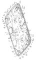
下部体20は、平面状に設けられた底面の周囲が上方側に徐々にせり上がるように形成されることで、内側になだらかな凹部が形成されている。底面にはガスコンロ1が載置された際に下部体20が載置台などに直接接触しないための脚部21が複数(図示例では5箇所)設けられている。図5に下部体20の斜視図を示す。下部体20にはバーナ13L,13R(下部体20の中央付近に設けられた突片23L,23Rに固定される)による燃焼のための空気を取り込む吸気孔25が複数設けられるとともに、下部体20の強度を補強するための補強壁部27(リブ)が複数箇所に設けられている。図示例では、下部体20の四隅と、短手辺の中間部とに一端がバーナに向かって立設される補強壁部27a,27b,27c,27d,27e,27fが設けられるとともに、下部体20の四隅における補強壁部27a〜27eに略直交する補強壁部27g、27h,27i,27j,27k,27lが設けられる。これら補強壁部27は上述のように下部体20の強度を補強する以外に、吸気孔25から取り込まれた空気の流れによって冷却されるため、いわゆる冷却フィンとしても機能し、コンロ本体100の内部温度の上昇及び下部体の加熱を抑制する。
The
そのため、複数設けられる吸気孔25のうちいくつかは、補強壁部27の近傍に設けられることが好ましく、図示例では、吸気孔25a,25b,25cが補強壁部27g、27hの、吸気孔25c、25dが補強壁部27eの、吸気孔25eが補強壁部27bの、吸気孔25fが補強壁部27iの、吸気孔25gが補強壁部27jの、吸気孔25hが補強壁部27cの、吸気孔25i、25jが補強壁部27fの、吸気孔25j,25k,25lが補強壁部27k、27lの、それぞれ近傍に設けられるものである。
Therefore, it is preferable that some of the plurality of
また、例えば補強壁部27e(27f)は吸気孔25c、25d(25i、25j)の近傍に設けられるとともに、吸気孔25c、25d(25i、25j)によって挟まれるように配置されることで、吸気孔25c、25d(25i、25j)から取り込まれた空気が補強壁部の両面側を流れるため、さらに冷却効果が高まるものである。また、図示例では補強壁部27a〜27fの一端側がバーナ13L,13R(突片23L,23R)に向かって配置されるため、これらの補強壁部によって吸気孔25からバーナに向かう空気の流れが過度に阻害されることがない。
Further, for example, the reinforcing
なお、下部体20は、熱伝導率が高く加工が容易な材料であるアルミニウムによって形成されるものである。これにより、例えばバーナ13L,13Rの直下が加熱された場合でも、加熱による熱が下部体全体に拡散(伝導)し易く、下部体20の温度分布が全体的になだらかになるため、一部分が過度に加熱され難くなっている。
The
図2〜図4に示されるように、上部体30は、平面状に設けられた上面の周囲が下方側に徐々に湾曲するように形成されており、上方側に向かってなだらかな凸状となっている。上部体30は、平面視において外形が下部体20と略同じとなっており、また材料も同様にアルミニウムとなっている。上部体30の上面には、中央付近に2箇所の開口部11L,11Rが長手方向(左右方向)に並んで設けられており、この開口部11L,11Rから下部体20に固定されたバーナ13L,13Rにおける複数の炎孔を有する燃焼部が臨むようになっている。図1に示すように、開口部11L,11Rには上述のように汁受け17L,17Rが載置されており、上部体30の上面には開口部11L,11R及び汁受け17L,17Rを囲繞するように五徳15L,15Rが載置される。
As shown in FIGS. 2 to 4, the
なお、図6に斜視図として示すように、汁受け17は平面視において中央にバーナ13が臨むための開口17cが設けられた円環板状であり、外周部17aが開口部11に掛止されるようになっている。図示例では、外周部17aにおいて下側に突き出した凸部17bが複数箇所(図示例では3箇所)設けられ、この凸部17bが開口部11周縁に接触することで汁受け17が上部体30に対して支持されるものである。そのため、凸部17b以外の部分では外周部17aが上部体30と接しておらず、これらの部分では汁受け17と上部体30との間に間隙が生じている。なお、上述の下部体20に設けられた吸気孔25から取り入れられた空気は、図7に矢印で示されるように、コンロ本体100の内側を流れて、汁受け17と上部体30との間に設けられた間隙を介してバーナ13の燃焼部に供給されるものである。
As shown in a perspective view in FIG. 6, the
図8に五徳15の下面側からの斜視図を、図9にガスコンロ1から五徳15を取り外した状態の平面図をそれぞれ示す。五徳15は、開口部11の周囲に設けられた複数の五徳載置部19の凹部19aに対して、この凹部19aに対応した五徳の凸部15aが支持されることで載置されるものである。これにより、上部体30における五徳15との接触部分は、この五徳載置部19のみとなる。このように接触部分が小面積に限定されることで加熱された五徳15からの熱が上部体30に伝導され難くなっている。そして、五徳載置部19は、断熱材によって形成されているため、さらに熱の伝導が小さくなっている。実施例における五徳載置部19は、開口部11の周囲に等間隔に4個設けられるものであり、例えばグラスファイバーによって形成されるものである。
FIG. 8 shows a perspective view from the lower surface side of the
図1〜図4に示されるように、断熱部材40は、平面視における外形が下部体20及び上部体30の外周縁と略同形を呈する枠状体であり、下部体20と上部体30との中間に配置されることによって、上部体30と下部体20とが接触せず熱の伝導が起こり難くなるようにしている。なお、外形が下部体20及び上部体30の外周縁と略同形であることにより、下部体20、上部体30及び断熱部材40の周面は略面一に形成されている。断熱部材40は例えばフェノール樹脂のような断熱性の高い樹脂材料によって形成される。
As shown in FIGS. 1 to 4, the
図10に斜視図として示すように、断熱部材40には、上下方向に貫通する貫通孔41が複数設けられている。そして、下部体20における、これらの貫通孔41に対応する位置には締結部22(図示例ではネジ孔)が設けられており、断熱部材40と下部体20とを重ね合わせた状態で断熱部材40側から貫通孔41及び締結部22に対して締結部材(例えばネジなど)を挿嵌することによって断熱部材40と下部体20とが締結される。
As shown in a perspective view in FIG. 10, the
また、下部体20は、図11に示される断面図に例示されるように、その四隅及び長手片の中間位置近傍に上部体30との締結用の貫通孔24が設けられ、上部体30には、これら貫通孔24に対応した位置に締結部34(図示例ではネジ孔)が設けられている。そして、上部体30の締結部34に対しては例えば樹脂製の断熱材によって形成された断熱スペーサ35が締結され、下部体20の底面外側から貫通孔24に挿通される締結部材29は断熱スペーサ35に挿嵌されることによって下部体20及び上部体30が断熱部材40及び断熱スペーサ35のみを介して接合されるものである。なお、図5に斜視図として示される下部体20は、断熱スペーサ35が取り付けられた状態で描画されているものである。
Further, as illustrated in the cross-sectional view shown in FIG. 11, the
図1に示すように、上部体30の外周縁は、その前面側の2箇所に切欠部31L,31R(総称するときは「切欠部31」とする)が設けられているため、上述のようにコンロ本体100が構成された際に、切欠部31から上方側に断熱部材40の一部が露出する。断熱部材40は、この露出した部分に長手方向に延びる一条の凹状のレール43L,43R(総称するときは「レール43」とする)が形成されている。このレール43には、バーナ13の着火や火加減の調節を行うための操作部45が、スライド自在に載置される。これにより、操作部45は、レール43をガイドとして長手方向に移動自在となる。なお、このように設けられた操作部45は、図12に示すように、断熱部材40とは接触するが、上部体30とは接触しないように、上部体30との間に所定の間隙Dが設けられ、この間隙Dによって操作部45と上部体30との間に空気層が形成される。これにより、上部体30からの熱が操作部45に対して直接的に伝導せず、操作部45が加熱され難くなっている。
As shown in FIG. 1, the outer peripheral edge of the
以上、本発明の実施の形態について図面を参照して詳述してきたが、具体的な構成は実施の形態に限られるものではなく、本発明の要旨を逸脱しない範囲の設計の変更等があっても本発明に含まれる。例えば、バーナ、吸気孔、補強壁部等の個数は一例であり、実施の形態に限定されるものではない。 The embodiment of the present invention has been described in detail with reference to the drawings. However, the specific configuration is not limited to the embodiment, and there are design changes and the like within the scope not departing from the gist of the present invention. Is included in the present invention. For example, the number of burners, intake holes, reinforcing wall portions, etc. is an example, and is not limited to the embodiment.
また、五徳載置部がグラスファイバーによって形成されている例を示したが、徳載置部は五徳からの熱が上部体に伝導し難くなるためのものであり、熱伝導率が小さければ有機材料、無機材料を含め、材料は特に限定されるものではない。 Moreover, although the example where the Gotoku placement part was formed with the glass fiber was shown, the Tokue placement part is for the heat from Gotoku to be difficult to conduct to the upper body, and it is organic if the thermal conductivity is small. Materials including materials and inorganic materials are not particularly limited.
上部体及び下部体がいずれもアルミニウムによって形成されている例を示したが、これに限定されない。例えば双方または一方をアルミニウム以外の金属材料や無機、有機材料を採用することとしても構わない。ただし、上部体及び下部体は、アルミニウムのような熱伝導率の高い材料を用いることにより、一部分が加熱された際にも熱が拡散しやすく局所的に加熱されることが抑制されるものであるため、アルミニウムのような熱伝導率の高い材料を用いることが好ましい。なお、アルミニウム以外にも熱伝導率が高い材料として銅などの他の材料を用いることを妨げないが、コスト面や加工性等からアルミニウムが好ましいものである。 Although the example in which the upper body and the lower body are both formed of aluminum is shown, the present invention is not limited to this. For example, both or one of them may adopt a metal material other than aluminum, an inorganic material, or an organic material. However, the upper body and the lower body are made of a material having high thermal conductivity such as aluminum, so that heat is easily diffused even when a part of the body is heated, and local heating is suppressed. Therefore, it is preferable to use a material having high thermal conductivity such as aluminum. In addition to aluminum, it is not prohibited to use other materials such as copper as a material having high thermal conductivity, but aluminum is preferable from the viewpoint of cost and workability.
1 ガスコンロ
11 開口部
13 バーナ
15 五徳
19 五徳載置部
20 下部体
25 吸気孔
27 補強壁部
30 上部体
31 切欠部
35 断熱スペーサ(固定手段)
40 断熱部材
43 レール
45 操作部
100 コンロ本体
DESCRIPTION OF
40 Heat insulation member 43
Claims (5)
前記コンロ本体は、前記バーナが固定される下部体と該下部体の上方に位置する上部体とからなり、
前記下部体及び上部体は樹脂製の断熱部材を介して接合されており、
前記上部体の外周縁の一部を切り欠くとともに、前記断熱部材の一部を上方に露出する切欠部と、
前記切欠部から上方に露出する断熱部材の上面にスライド自在に設けられた前記バーナの操作部と、を備えていることを特徴とするガスコンロ。 A gas stove with a burner contained in the stove body,
The stove body comprises a lower body to which the burner is fixed and an upper body located above the lower body,
The lower body and the upper body are joined via a heat insulating member made of resin ,
Notch part of the outer peripheral edge of the upper body, and a notch part exposing a part of the heat insulating member upward,
And a burner operating portion slidably provided on an upper surface of a heat insulating member exposed upward from the notch .
前記上部体、下部体及び断熱部材の外周縁が略面一に形成されていることを特徴とする請求項1又は2記載のガスコンロ。 The heat insulating member is provided around the entire upper body and lower body,
The gas stove according to claim 1 or 2, wherein outer peripheries of the upper body, the lower body, and the heat insulating member are substantially flush with each other.
Priority Applications (1)
| Application Number | Priority Date | Filing Date | Title |
|---|---|---|---|
| JP2011012224A JP5565965B2 (en) | 2011-01-24 | 2011-01-24 | Gas stove |
Applications Claiming Priority (1)
| Application Number | Priority Date | Filing Date | Title |
|---|---|---|---|
| JP2011012224A JP5565965B2 (en) | 2011-01-24 | 2011-01-24 | Gas stove |
Publications (2)
| Publication Number | Publication Date |
|---|---|
| JP2012154519A JP2012154519A (en) | 2012-08-16 |
| JP5565965B2 true JP5565965B2 (en) | 2014-08-06 |
Family
ID=46836435
Family Applications (1)
| Application Number | Title | Priority Date | Filing Date |
|---|---|---|---|
| JP2011012224A Expired - Fee Related JP5565965B2 (en) | 2011-01-24 | 2011-01-24 | Gas stove |
Country Status (1)
| Country | Link |
|---|---|
| JP (1) | JP5565965B2 (en) |
Family Cites Families (2)
| Publication number | Priority date | Publication date | Assignee | Title |
|---|---|---|---|---|
| JP3418113B2 (en) * | 1998-01-30 | 2003-06-16 | リンナイ株式会社 | Stove |
| JP2004251589A (en) * | 2003-02-21 | 2004-09-09 | Rinnai Corp | Cooking stove |
-
2011
- 2011-01-24 JP JP2011012224A patent/JP5565965B2/en not_active Expired - Fee Related
Also Published As
| Publication number | Publication date |
|---|---|
| JP2012154519A (en) | 2012-08-16 |
Similar Documents
| Publication | Publication Date | Title |
|---|---|---|
| US20180100658A1 (en) | Ventilation System for Induction Cooktop | |
| US8692169B2 (en) | Electrical apparatus having active heat-dissipating element and air circulating system having such electrical apparatus | |
| JP2013520834A (en) | Small multilayer radiant cooling case with hidden quick release snap | |
| TWI578911B (en) | Barbeque stove | |
| JP6022271B2 (en) | Cooker | |
| JP5565965B2 (en) | Gas stove | |
| JP5560211B2 (en) | Gas stove | |
| JP2012154517A (en) | Gas cooking stove | |
| JP2016085008A (en) | Air conditioner | |
| JP6189677B2 (en) | Cooker | |
| JP2015010756A (en) | Heating cooker | |
| CN104235886A (en) | Gas stove | |
| JP2017219288A (en) | Heating device | |
| JP6731729B2 (en) | Hob | |
| CN221055095U (en) | Heat insulation assembly and kitchen range | |
| JP6639161B2 (en) | Cooker | |
| JP6615693B2 (en) | Heating equipment | |
| JP2019152395A (en) | Built-in stove | |
| CN216114193U (en) | Cooking utensil | |
| JP6615694B2 (en) | Heating equipment | |
| JP2006010281A (en) | Mounting structure of top plate for cooking stove | |
| JP6721985B2 (en) | Hob | |
| JP2017176249A (en) | Cooking stove | |
| JP6227929B2 (en) | Cooker | |
| KR20160119668A (en) | Cap of gas range |
Legal Events
| Date | Code | Title | Description |
|---|---|---|---|
| A621 | Written request for application examination |
Free format text: JAPANESE INTERMEDIATE CODE: A621 Effective date: 20130221 |
|
| A977 | Report on retrieval |
Free format text: JAPANESE INTERMEDIATE CODE: A971007 Effective date: 20140220 |
|
| A131 | Notification of reasons for refusal |
Free format text: JAPANESE INTERMEDIATE CODE: A131 Effective date: 20140225 |
|
| A521 | Written amendment |
Free format text: JAPANESE INTERMEDIATE CODE: A523 Effective date: 20140416 |
|
| TRDD | Decision of grant or rejection written | ||
| A01 | Written decision to grant a patent or to grant a registration (utility model) |
Free format text: JAPANESE INTERMEDIATE CODE: A01 Effective date: 20140520 |
|
| A61 | First payment of annual fees (during grant procedure) |
Free format text: JAPANESE INTERMEDIATE CODE: A61 Effective date: 20140616 |
|
| R150 | Certificate of patent or registration of utility model |
Ref document number: 5565965 Country of ref document: JP Free format text: JAPANESE INTERMEDIATE CODE: R150 |
|
| R250 | Receipt of annual fees |
Free format text: JAPANESE INTERMEDIATE CODE: R250 |
|
| R250 | Receipt of annual fees |
Free format text: JAPANESE INTERMEDIATE CODE: R250 |
|
| R250 | Receipt of annual fees |
Free format text: JAPANESE INTERMEDIATE CODE: R250 |
|
| LAPS | Cancellation because of no payment of annual fees |