JP5563311B2 - Fluid torque converter - Google Patents
Fluid torque converter Download PDFInfo
- Publication number
- JP5563311B2 JP5563311B2 JP2009547742A JP2009547742A JP5563311B2 JP 5563311 B2 JP5563311 B2 JP 5563311B2 JP 2009547742 A JP2009547742 A JP 2009547742A JP 2009547742 A JP2009547742 A JP 2009547742A JP 5563311 B2 JP5563311 B2 JP 5563311B2
- Authority
- JP
- Japan
- Prior art keywords
- reactor
- vane
- turbine
- edge
- impeller
- Prior art date
- Legal status (The legal status is an assumption and is not a legal conclusion. Google has not performed a legal analysis and makes no representation as to the accuracy of the status listed.)
- Active
Links
- 239000012530 fluid Substances 0.000 title claims description 48
- 238000013459 approach Methods 0.000 claims description 11
- 230000005540 biological transmission Effects 0.000 claims description 4
- 230000007423 decrease Effects 0.000 description 5
- 238000004088 simulation Methods 0.000 description 4
- 230000001133 acceleration Effects 0.000 description 1
- 230000000712 assembly Effects 0.000 description 1
- 238000000429 assembly Methods 0.000 description 1
- 238000004364 calculation method Methods 0.000 description 1
- 238000006243 chemical reaction Methods 0.000 description 1
- 230000008878 coupling Effects 0.000 description 1
- 238000010168 coupling process Methods 0.000 description 1
- 238000005859 coupling reaction Methods 0.000 description 1
Images


Classifications
-
- F—MECHANICAL ENGINEERING; LIGHTING; HEATING; WEAPONS; BLASTING
- F16—ENGINEERING ELEMENTS AND UNITS; GENERAL MEASURES FOR PRODUCING AND MAINTAINING EFFECTIVE FUNCTIONING OF MACHINES OR INSTALLATIONS; THERMAL INSULATION IN GENERAL
- F16H—GEARING
- F16H41/00—Rotary fluid gearing of the hydrokinetic type
- F16H41/24—Details
-
- F—MECHANICAL ENGINEERING; LIGHTING; HEATING; WEAPONS; BLASTING
- F16—ENGINEERING ELEMENTS AND UNITS; GENERAL MEASURES FOR PRODUCING AND MAINTAINING EFFECTIVE FUNCTIONING OF MACHINES OR INSTALLATIONS; THERMAL INSULATION IN GENERAL
- F16H—GEARING
- F16H41/00—Rotary fluid gearing of the hydrokinetic type
- F16H41/04—Combined pump-turbine units
-
- F—MECHANICAL ENGINEERING; LIGHTING; HEATING; WEAPONS; BLASTING
- F16—ENGINEERING ELEMENTS AND UNITS; GENERAL MEASURES FOR PRODUCING AND MAINTAINING EFFECTIVE FUNCTIONING OF MACHINES OR INSTALLATIONS; THERMAL INSULATION IN GENERAL
- F16H—GEARING
- F16H41/00—Rotary fluid gearing of the hydrokinetic type
- F16H41/24—Details
- F16H41/26—Shape of runner blades or channels with respect to function
Landscapes
- Engineering & Computer Science (AREA)
- General Engineering & Computer Science (AREA)
- Mechanical Engineering (AREA)
- Control Of Fluid Gearings (AREA)
Description
本発明は、流体トルクコンバータに関し、より詳細には、自動変速機用に使用される流体トルクコンバータに関する。 The present invention relates to a fluid torque converter, and more particularly to a fluid torque converter used for an automatic transmission.
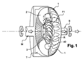
従来技術として、米国特許第5,168,702号の図1には、流体力学的クラッチとして自動車の分野で使用されるトルクコンバータが開示されている。このトルクコンバータは、
・エンジン(図示せず)に結合された入力シャフトMによって駆動され、1組のインペラーベーン1を備え、かつ軸線Aを有するインペラーIと、
・出力シャフトSを駆動し、前記インペラーベーン1の組に対向する、1組のタービンベーン2を備え、かつ軸線Aを有するタービンTと、
・前記軸線Aを中心としてフリーホイールに取り付けられ、前記タービンベーンの組と前記インペラーベーンの組との間に位置する1組のリアクタベーン3を有するリアクタRとを備えている。ここで、「フリーホイールに取り付けられ」という表現は、前記リアクタが、軸線Aを中心として一方向にしか回転できないことを意味し、反対の方向を「ロックされた方向」と呼ぶ。
As prior art, FIG. 1 of US Pat. No. 5,168,702 discloses a torque converter for use in the automotive field as a hydrodynamic clutch. This torque converter
An impeller I driven by an input shaft M coupled to an engine (not shown) and comprising a set of
A turbine T that drives the output shaft S and has a set of
A reactor R that is attached to a freewheel about the axis A and has a set of
インペラーベーン1、タービンベーン2、リアクタベーン3は、それぞれ内側縁11;21;31、外側縁12;22;32、後縁13;23;33、および前縁14;24;34を有し、タービンベーン21とリアクタベーン31は、軸線Aを中心とするこれらのベーンの回転中に、軸線Aを中心とする回転体40の内側コアを構成している。
これらベーンのアセンブリは、シールされたハウジング内に配置されており、シールされたハウジングには、粘性指標は小さいが、高密度である一定量の流体、一般にはオイルが入れられている。コンバータの場合、このシールされたハウジングは、前記流体によって完全に満たされている。 These vane assemblies are placed in a sealed housing that contains a certain amount of fluid, typically oil, that has a low viscosity index but a high viscosity. In the case of a converter, this sealed housing is completely filled with the fluid.
流体トルクコンバータは、自動車が徐々にスタートできるようにすると共に、タービンの回転速度とインペラーの回転速度との比iが小さいとき、例えば0.5より小さいとき、好ましくは0.2より小さいときに、トルクを増大させるようになっている。 The fluid torque converter allows the vehicle to start gradually and when the ratio i between the turbine rotational speed and the impeller rotational speed is small, for example smaller than 0.5, preferably smaller than 0.2. The torque is increased.
これら回転速度の比iは、
i=NT/NI
と定義される。
The ratio i of these rotational speeds is
i = N T / N I
It is defined as
ここで、NTおよびNIは、それぞれ、1分当たりの回転数を単位とするタービンの回転速度、およびインペラーの回転速度を示す。 Here, N T and N I, respectively, indicating the revolutions per minute speed of the turbine units, and the rotational speed of the impeller.
エンジンがアイドリング状態にあるとき、インペラーはエンジンと同じ速度で回転し、タービンは若干のスラスト力を受けるが、リアクタは回転しない。 When the engine is idling, the impeller rotates at the same speed as the engine and the turbine receives some thrust, but the reactor does not rotate.
エンジンが加速するが、自動車が停止状態のままであるか、または移動し始めるとき、インペラーの回転運動は、回転体40の内側コアを中心とする、矢印F1が示す螺旋運動をオイルに伝える。次に前記タービンは、オイルの流れを受け、オイルの運動エネルギーの大部分は、タービンに伝えられる。次にタービンは、出力シャフトにトルクを伝え、出力シャフトを回転させる。
As the engine accelerates but the car remains stationary or begins to move, the impeller's rotational motion imparts to the oil the spiral motion indicated by arrow F1 about the inner core of the rotating
リアクタは、タービンからのオイルの流れを好ましい角度で受け、リアクタベーン2を強制的にロック方向に移動させる。リアクタは、この流れをインペラーベーン2の背面に、バランスのとれた状態で送る。従って、インペラーベーン2の背面は、リアクタから誘導された流体を受け、インペラーは、この流体を再びタービンへ伝え、タービンのトルクが増大する。このステップは、コンバータフェーズと称される。好ましいことであるが、流体トルクコンバータは、コンバータフェーズ中に、エンジンのトルクを1以上の倍率で増大させる。従って、タービンのトルクは、インペラーのトルク以上となる。
The reactor receives the oil flow from the turbine at a preferred angle and forcibly moves the
タービンの回転速度が徐々に増加し、インペラーの速度に接近すると、オイルの流れは、異なる角度でリアクタの方向に送られる。リアクタは、リアクタベーン2の延長部内でオイルの流れを受け始め、次に、タービンがインペラーと実質的に同じ速度で回転すると、リアクタベーン2の背面で、オイルの流れを受け始める。リアクタベーン2の背面は、フリーホイールの自由方向にリアクタを共に駆動する流体を受ける。従って、リアクタは、軸線Aを中心として回転することができ、次にタービンおよびインペラーと実質的に同じ速度で回転させる。
As the turbine's rotational speed increases gradually and approaches the impeller speed, the oil flow is directed toward the reactor at different angles. The reactor begins to receive oil flow within the extension of the
一般に、作動フェーズを2つの作動フェーズ、すなわち、0〜0.8のレンジ内にある比iに広く対応するコンバータフェーズと称されるフェーズと、クラッチにロックされたときのレンジ0.8〜1にある比iに広く対応する継手フェーズとに区別できる。 In general, the operating phase is divided into two operating phases: a phase referred to as a converter phase that corresponds broadly to a ratio i in the range of 0 to 0.8, and a range of 0.8 to 1 when locked to the clutch. It can be distinguished from the joint phase that corresponds widely to the ratio i.
トルク変換が終了すると、流体トルクコンバータは、単なる流体継手として作動する。 When the torque conversion is completed, the fluid torque converter operates as a simple fluid coupling.
この流体トルクコンバータを使用すると、次のような利点が得られる。
・機械式クラッチを用いた場合よりも、漸増性およびフレキシビリティが良好となる。
・ギア切り替えの頻度が少なくなる。
・エンジンおよび変速機の機械的要素の寿命が長くなる。
The use of this fluid torque converter provides the following advantages.
-Gradual increase and flexibility are better than when a mechanical clutch is used.
・ The frequency of gear change decreases.
-The life of the mechanical elements of the engine and transmission is increased.
トルクコンバータでは、そのトルク比は、次のように定義される。
TR=CT/CP
CTは、タービンのトルクであり、CPは、インペラーのトルクである。トルクコンバータのトルク比は、上記のように定義される回転速度の比iを関数として変化する。
In the torque converter, the torque ratio is defined as follows.
TR = C T / C P
C T is the turbine torque, and C P is the impeller torque. The torque ratio of the torque converter changes as a function of the rotational speed ratio i defined as described above.
流体トルクコンバータのトルク容量MPは、インペラーが1000rpm-1で回転するときに、インペラーによって吸収されるトルク(単位Nm)として定められる。この流体トルクコンバータのトルク容量は、上記のように定義される速度の比iに応じて決まる。 Torque capacity M P of the fluid torque converter impeller when rotating at 1000 rpm -1, it is defined as the torque (unit Nm) that is absorbed by the impeller. The torque capacity of the fluid torque converter is determined according to the speed ratio i defined as described above.
コンバータのトルク容量は、エンジンのトルク特性に応じて選択される。トルク容量がエンジントルクに対して過度に大きい場合、自動車がスタートするときに、エンジンの回転速度は十分には増加せず、自動車はスムーズに発進しない。逆に、トルクコンバータのトルク容量がエンジントルクと比較して過度に小さい場合、エンジンは空回り状態となり、自動車は期待される加速性能を発揮しない。 The torque capacity of the converter is selected according to the engine torque characteristics. If the torque capacity is excessively large with respect to the engine torque, when the automobile starts, the engine speed does not increase sufficiently and the automobile does not start smoothly. Conversely, if the torque capacity of the torque converter is excessively small compared to the engine torque, the engine will run idle and the vehicle will not exhibit the expected acceleration performance.
従来、流体トルクコンバータは、高トルク比または高トルク容量のいずれかを有することが知られている。すなわち、コンバータがシェルによって構成されている回転体の内側コアを含むとき、容積が固定された場合にトルク容量が増加すれば、トルク比は減少する。例えば日本国公開特許出願第JP05-296344号に記載されているように、回転体の内側コアを有しないコンバータの場合、トルク比の増加に伴い、トルク容量が減少する。 Conventionally, fluid torque converters are known to have either a high torque ratio or a high torque capacity. That is, when the converter includes the inner core of the rotating body constituted by the shell, the torque ratio decreases if the torque capacity increases when the volume is fixed. For example, as described in Japanese Patent Application Publication No. JP05-296344, in the case of a converter that does not have an inner core of a rotating body, the torque capacity decreases as the torque ratio increases.
従って、最低トルク比を維持しながら、容積が固定された状態で、トルクコンバータのトルク容量を高めたいというニーズが存在する。 Accordingly, there is a need to increase the torque capacity of the torque converter while maintaining a minimum torque ratio and a fixed volume.
本発明の目的は、このニーズを満たすことにある。 The object of the present invention is to satisfy this need.
本発明は、
軸線Aに対して同心状に配置されており、各々インペラーベーン1、タービンベーン2、およびリアクタベーン3が設けられているインペラーIと、タービンTと、リアクタRとを備え、各ベーンは、内側縁部11;21;31と、外側縁部12;22;32と、後縁部13;23;33と、前縁部14;24;34とによって構成されており、
前記タービンベーン2の組は、タービンベーンが回転する間、タービンの包絡面52を構成し、前記包絡面52は、前記タービンベーンの回転中に、前記タービンベーン2のうちの内側縁部21、後縁部23および前縁部24によってそれぞれ構成されるタービンの内側表面62と、タービンの後方表面82と、タービンの前方表面92とを備え、
前記インペラー1の組は、インペラーが回転する間、インペラーの包絡面51を構成し、前記包絡面51は、前記タービンの回転中に、前記インペラー1のうちの内側縁部11、後縁部13および前縁部14によってそれぞれ構成されるインペラーの内側表面61と、インペラーの後方表面81と、インペラーの前方表面91とを備え、
前記リアクタベーン3の組は、リアクタベーンが回転する間、リアクタの包絡面53を構成し、前記包絡面53は、前記リアクタベーンの回転中に、前記リアクタベーン3のうちの内側縁部31、後縁部33および前縁部34によってそれぞれ構成されるリアクタの内側表面63と、リアクタの後方表面83と、タービンの前方表面93とを備え、
前記タービン、インペラー、およびリアクタの前記表面は、共に内側コアの包絡面を構成し、
前記インペラーの後方表面81は、前記タービンの前方表面92から軸方向外側に距離d1だけ離間しており、前記タービンの後方表面82は、前記リアクタの前方表面93から軸方向内側に距離d2だけ離間しており、前記軸方向外側距離と前記軸方向内側距離とは、互いに最も接近する対向ポイントにおける当該表面の間の軸方向最小距離にそれぞれ対応している、自動車用流体トルクコンバータであって、
前記流体トルクコンバータは、距離の比d2/d1が1.4以下であり、前記リアクタは、少なくとも1つのリアクタベーン3を備えており、リアクタベーン3の縁部(31,33,34)は、回転中にリアクタベーン3が占める最大容積を構成するリアクタの包絡面53を実質的に形成するようになっており、このリアクタベーン3の前縁部34は、回転中に前記リアクタの前方表面93を構成して、タービンの後方表面82に接近するようになっており、もって前記リアクタベーン3は、「縁部接近型」リアクタベーンとされていることを特徴とする、流体トルクコンバータを提供するものである。
The present invention
It is arranged concentrically with respect to the axis A, and includes an impeller I provided with an
The set of
The set of
The set of
The turbine, impeller, and reactor surfaces together form an inner core envelope,
The impeller
The fluid torque converter, the distance ratio of d2 / d1 is 1.4 or less, wherein the reactor is provided with at least one
本発明者たちは、リアクタベーンの前縁部を、タービンベーンの後縁部に接近させると、意外にも、満足できるトルク比を維持しながら、トルクコンバータのトルク容量を大幅に増大できることを発見した。 The inventors have unexpectedly discovered that bringing the reactor vane leading edge closer to the turbine vane trailing edge can significantly increase the torque capacity of the torque converter while maintaining a satisfactory torque ratio. did.
トルクコンバータのサイズ、およびタービン並びにインペラーの可撓性から、タービンとインペラーとの間の間隔d1が得られる。この間隔は、作動フェーズにもかかわらず、タービンベーンとインペラーベーンとが全く接触しないような大きさとなっている(トルクの増大(0<i<0.8)中のコンバータフェーズでは、インペラーの後縁部とタービンの前縁部とは互いに接近している)。この寸法上の基準は、主にトルクコンバータの幾何学的形状および剛性にリンクしていることが好ましく、コンバータの性能に大きくリンクしないことが望ましい。 From the size of the torque converter and the flexibility of the turbine and impeller, the distance d1 between the turbine and the impeller is obtained. This interval is so large that the turbine vane and the impeller vane do not contact at all in spite of the operation phase (in the converter phase during torque increase (0 <i <0.8), The edge and the front edge of the turbine are close together). This dimensional criterion is preferably linked primarily to the geometry and stiffness of the torque converter and preferably not significantly linked to converter performance.
パラメータ研究(有限要素計算)により、リアクタの前縁部をタービンの後縁部に接近させると、トルクコンバータのトルク容量を増加できることが実証された。このようなd2/d1の比を使用することにより、本発明によれば、好都合にも、このような接近とトルクコンバータの全体の寸法とが無関係になるという特性が得られる。更に、このような比は、部品が変形するときのリアクタに対するタービンの接近を考慮できることを意味する。(コンバータフェーズ中の)トルク増大中に、インペラーの後縁部がタービンの前縁部に接近すると、タービンの後縁部もリアクタの前縁部に接近する。d2/d1の比の下限は、タービンの後縁部とリアクタの前縁部の間の最小の間隙d2も考慮したものである。 Parametric studies (finite element calculations) have demonstrated that the torque capacity of the torque converter can be increased by bringing the reactor leading edge closer to the turbine trailing edge. By using such a ratio of d2 / d1, the present invention advantageously provides the property that such access is independent of the overall dimensions of the torque converter. Furthermore, such a ratio means that the turbine's proximity to the reactor as the part deforms can be taken into account. During the torque increase (during the converter phase), when the impeller trailing edge approaches the turbine leading edge, the turbine trailing edge also approaches the reactor leading edge. The lower limit of the ratio d2 / d1 also takes into account the minimum gap d2 between the turbine trailing edge and the reactor leading edge.
本発明のトルクコンバータは、複数の「縁部接近型」リアクタベーンを備えていることが望ましい。前記ベーンはリアクタの周辺に規則的に分布させていることが好ましい。リアクタベーンの組、すなわちすべてのリアクタベーンが縁部接近型であるのが望ましい。本発明のトルクコンバータは、「縁部接近型」リアクタベーンと、これの前縁部よりタービンの後縁部から遠くなるように形成された前縁部を有するリアクタベーンとが交互に配置された構成を有していてもよい。
The torque converter of the present invention, it is desirable to provide a plurality of "edge close type" Riakutabe down. The vanes are preferably distributed regularly around the reactor. Desirably, the set of reactor vanes, i.e. all reactor vanes, are edge- closed. In the torque converter of the present invention, “edge approaching” reactor vanes and reactor vanes having front edges formed so as to be farther from the rear edge of the turbine than the front edges thereof are alternately arranged. You may have a structure.
最後に、本発明は、上記本発明に係わる流体トルクコンバータを備えることを特徴とする自動車用自動変速機にも関する。
以下の説明および添付図面を検討すれば、本発明の上記以外の特徴および利点が明らかとなると思う。
Finally, the present invention also relates to an automatic transmission for an automobile characterized by including the fluid torque converter according to the present invention.
Other features and advantages of the present invention will become apparent from consideration of the following description and accompanying drawings.
次に、図2を参照する。この図2は、本発明に係わる流体トルクコンバータのインペラーベーン1と、タービンベーン2と、リアクタベーン3とを、高度に簡略化した状態で示している。
Reference is now made to FIG. FIG. 2 shows the
各インペラーベーン1は、内側縁部11と、外側縁部12と、後縁部13と、前縁部14を有している。
Each
各タービンベーン2は、内側縁部21と、外側縁部22と、後縁部23と、前縁部24とを有している。
Each
各リアクタベーン3は、内側縁部31と、外側縁部32と、後縁部33と、前縁部34とを有している。
Each
インペラー、タービン、およびリアクタベーンの内側縁部は、これらの軸線Aを中心とする回転中に、軸線Aを中心とする回転体40の内側コアを構成している。
The inner edges of the impeller, turbine, and reactor vane constitute the inner core of the
次に図3を参照する。インペラーベーン、リアクタベーン、およびタービンベーンは、それらが回転する間、それぞれインペラーの包絡面51、タービンの包絡面52、およびリアクタの包絡面53を構成する。
Reference is now made to FIG. The impeller vane, the reactor vane, and the turbine vane constitute an
「インペラーの包絡面、タービンの包絡面およびリアクタの包絡面」なる用語は、軸線Aを中心とするこれらの回転中に、それぞれインペラー、タービンおよびリアクタベーンが占める最大容積を構成する表面を意味する。 The terms “impeller envelope, turbine envelope and reactor envelope” refer to the surfaces that make up the maximum volume occupied by the impeller, turbine and reactor vanes, respectively, during their rotation about axis A. .
更に「縁部接近型」リアクタベーンなる用語は、これらベーンの回転中に前縁部がリアクタの包絡面における前方表面を実質的に形成するリアクタベーンを意味する。このリアクタは、前縁部が、「縁部接近型」ベーンの前縁部よりもタービンの後縁部から、遠くなっているベーンも含むことができる。このようなベーンの縁部は、回転中にリアクタの包絡面を形成することはない。
Furthermore, the term " edge approach " reactor vanes refers to reactor vanes in which the leading edge substantially forms the front surface of the reactor envelope during rotation of the vanes. The reactor may also include a vane whose leading edge is farther from the trailing edge of the turbine than the leading edge of the “ edge approaching ” vane. Such vane edges do not form the envelope of the reactor during rotation.
前記タービンの包絡面52は、タービンベーンの組が回転中にこれらタービンベーンの内側縁部、外側縁部、後縁部および前縁部によってそれぞれ構成されるタービンの内側表面62と、タービンの外側表面72と、タービンの後方表面82と、タービンの前方表面92とを含んでいる。
The
前記インペラーの包絡面51は、インペラーベーンの組が、回転中にこれらインペラーベーンの内側縁部、外側縁部、後縁部、および前縁部によってそれぞれ構成されるインペラーの内側表面61と、インペラーの外側表面71と、インペラーの後方表面81と、インペラーの前方表面91を含んでいる。
The
前記リアクタの包絡面53は、リアクタベーンの組が、回転中にこれらリアクタベーンの内側縁部、外側縁部、後縁部および前縁部によってそれぞれ構成されるリアクタの内側表面63と、リアクタの外側表面73と、リアクタの後方表面83と、リアクタの前方表面93を含んでいる。
The
軸方向距離d1は、互いに接近している前記対向表面のポイントにおける、インペラーの後方表面81とタービンの前方表面92との間のトルクコンバータの軸線Aに沿う最小距離である。
The axial distance d1 is the minimum distance along the axis A of the torque converter between the impeller
同様に、軸方向距離d2は、互いに接近している前記対向表面のポイントにおける、タービンの後方表面82とリアクタの前方表面93との間のトルクコンバータの軸線Aに沿う距離である。
Similarly, the axial distance d2 is the distance along the torque converter axis A between the turbine
本発明によれば、距離の比d2/d1は、1.4以下、好ましくは1.1以下であり、かつ好ましくは0.6以上、より好ましくは0.9以上である。距離d2/d1の比は、ほぼ1であることが好ましい。 According to the present invention, the distance ratio d2 / d1 is 1.4 or less, preferably 1.1 or less, and preferably 0.6 or more, more preferably 0.9 or more. The ratio of distance d2 / d1 is preferably approximately 1.
本発明によるd2/d1の上記の範囲は、図6から分かるように、最大トルク容量を得るためのゾーンを定めるのが好ましい。d2/d1の最小値を超えると、流体が剪断され、トルク容量は低下し、d2/d1の最大値を超えると、トルク容量は低下する。 The above range of d2 / d1 according to the present invention preferably defines a zone for obtaining the maximum torque capacity, as can be seen from FIG. When the minimum value of d2 / d1 is exceeded, the fluid is sheared and the torque capacity decreases, and when the maximum value of d2 / d1 is exceeded, the torque capacity decreases.
このような構成により、トルク比を満足できるレベルに維持しながら、トルク容量を高めることができることが分かった。 It has been found that such a configuration can increase the torque capacity while maintaining the torque ratio at a satisfactory level.
従って、図6は、d2/d1の比の関数として、(i=0のとき)本発明の流体トルクコンバータのストール時のトルク容量Mpを与えるシミュレーションの結果を示している。このことから、本発明に係わるd2/d1のレンジが分かる。 Accordingly, FIG. 6 shows the results of a simulation that gives the torque capacity Mp at stall of the fluid torque converter of the present invention (when i = 0) as a function of the ratio d2 / d1. From this, the d2 / d1 range according to the present invention can be understood.
図4は、速度比が0〜0.8の場合の3つのタイプの流体トルクコンバータにおけるシミュレートされたトルク容量Mpを示す。曲線101は、従来の流体トルクコンバータに対応するので、「縁部接近型」リアクタベーンは有していない。曲線102は、リアクタベーンのすべてが「縁部接近型」であり、この「縁部接近型」ベーンにおける距離の比d2/d1が0.61である流体トルクコンバータに対応し、曲線103は、「縁部接近型」リアクタベーンと、これの前縁部よりタービンの後縁部から遠くなるように形成された前縁部を有するリアクタベーンとが交互に配置されており、この「縁部接近型」ベーンでの距離の比d2/d1が0.61となっている流体トルクコンバータに対応している。図4および図5における距離のかかる比d2/d1は、d2/d1の提案されたレンジ内にある。かかる一定の比では、リアクタにおける2つの可能な構造の影響を予測できる。
FIG. 4 shows the simulated torque capacity Mp in three types of fluid torque converters for speed ratios from 0 to 0.8. Since
従来の流体トルクコンバータに対し、本発明の流体トルクコンバータによれば、40%までのトルク容量の改善が見られる。 Compared to the conventional fluid torque converter, according to the fluid torque converter of the present invention, the torque capacity is improved by 40%.
次に図5を参照し、図4と同じ3つの流体トルクコンバータにおけるシミュレートされたトルク比TRを検討する。 Next, referring to FIG. 5, consider the simulated torque ratio TR in the same three fluid torque converters as in FIG.
これら3つのタイプの流体トルクコンバータの間で、トルク比が極めて類似していることが観察される。 It is observed that the torque ratios are very similar between these three types of fluid torque converters.
従って、本発明のトルクコンバータは、高いトルク容量と、従来のトルクコンバータのトルク比に近いトルク比を有する。 Therefore, the torque converter of the present invention has a high torque capacity and a torque ratio close to the torque ratio of the conventional torque converter.
本発明は、説明のための非限定的な例と、図示した実施形態だけに限定されるものではなく、特に「縁部接近型」リアクタの分布を変えることができる。
The present invention is not limited to the illustrative non-limiting examples and illustrated embodiments, and in particular the distribution of the “ edge approach ” reactor can be varied.
I インペラー
T タービン
R リアクタ
M 入力シャフト
S 出力シャフト
1 インペラーベーン
2 タービンベーン
3 リアクタベーン
11、21、 31 内側縁部
12、22、 32 外側縁部
13、23、33 後縁部
14、24、34 前縁部
51、52、53 包絡面
61、62、63 内側表面
71、72、73 外側表面
81、82、83 後方表面
91、92、93 前方表面
I Impeller T Turbine R Reactor M Input shaft
Claims (9)
前記タービンベーン(2)の組は、このタービンベーンが回転する間、タービンの包絡面(52)を構成し、この包絡面(52)は、前記タービンベーンの回転中に、前記タービンベーン(2)のうちの内側縁部(21)、後縁部(23)、および前縁部(24)によってそれぞれ構成されるタービンの内側表面(62)と、タービンの後方表面(82)と、タービンの前方表面(92)とを備え、
前記インペラーベーン(1)の組は、このインペラーベーンが回転する間、インペラーの包絡面(51)を構成し、前記包絡面(51)は、前記タービンベーンの回転中に、前記インペラーベーン(1)のうちの内側縁部(11)、後縁部(13)、および前縁部(14)によってそれぞれ構成されるインペラーの内側表面(61)と、インペラーの後方表面(81)と、インペラーの前方表面(91)とを備え、
前記リアクタベーン(3)の組は、このリアクタベーンが回転する間、リアクタの包絡面(53)を構成し、前記包絡面(53)は、前記リアクタベーンの回転中に、前記リアクタベーン(3)のうちの内側縁部(31)、後縁部(33)、および前縁部(34)によってそれぞれ構成されるリアクタの内側表面(63)と、リアクタの後方表面(83)と、リアクタの前方表面(93)とを備え、
前記タービン、インペラー、およびリアクタの前記内側表面は、共に内側コアの包絡面を構成し、
前記インペラーの後方表面(81)は、前記タービンの前方表面(92)から軸方向外側に距離d1だけ離間しており、前記タービンの後方表面(82)は、前記リアクタの前方表面(93)から軸方向内側に距離d2だけ離間しており、前記軸方向外側距離と前記軸方向内側距離とは、互いに最も接近する対向ポイントにおける当該表面の間の軸方向最小距離にそれぞれ対応している、流体トルクコンバータであって、
前記距離の比d2/d1は、1.4以下であり、前記リアクタは、少なくとも1つの前記リアクタベーン(3)を備えており、前記リアクタベーン(3)の縁部(31,33,34)は、回転中に前記リアクタベーン(3)が占める最大容積を構成する前記リアクタの包絡面(53)を実質的に形成するようになっており、前記リアクタベーン(3)の前縁部(34)は、回転中に前記リアクタの前方表面(93)を構成して、前記タービンの後方表面(82)に接近するようになっており、もって前記リアクタベーン(3)は、「縁部接近型」リアクタベーンとされていることを特徴とする流体トルクコンバータ。 An impeller (I) arranged concentrically with respect to the axis A, each provided with an impeller vane (1), a turbine vane (2), and a reactor vane (3), a turbine (T), and a reactor (R), each vane having an inner edge (11; 21; 31), an outer edge (12; 22; 32), a rear edge (13; 23; 33), and a front edge (14; 24; 34) and
The set of turbine vanes (2) constitutes an envelope surface (52) of the turbine during rotation of the turbine vane, and the envelope surface (52) is the turbine vane (2) during rotation of the turbine vane. ), An inner surface (62) of the turbine, a rear surface (82) of the turbine, and a turbine rear surface (82), each of which is constituted by an inner edge (21), a rear edge (23), and a front edge (24). A front surface (92),
The set of impeller vanes (1) constitutes an impeller enveloping surface (51) while the impeller vane rotates, and the enveloping surface (51) is in the impeller vane (1) during the rotation of the turbine vane. ), The inner surface (61) of the impeller constituted by the inner edge portion (11), the rear edge portion (13) and the front edge portion (14), the rear surface (81) of the impeller, and the impeller A front surface (91),
The set of reactor vanes (3) constitutes the envelope surface (53) of the reactor while the reactor vane rotates, and the envelope surface (53) is the reactor vane (3) during the rotation of the reactor vane. ), The reactor inner surface (63), the reactor rear surface (83), the reactor rear surface (83), and the reactor rear surface (83) respectively. A front surface (93),
The turbine, impeller, and the inner surface of the reactor together constitute an envelope of the inner core,
The rear surface (81) of the impeller is spaced axially outward from the front surface (92) of the turbine by a distance d1, and the rear surface (82) of the turbine is separated from the front surface (93) of the reactor. A fluid separated axially inward by a distance d2, wherein the axially outer distance and the axially inner distance correspond respectively to a minimum axial distance between the surfaces at opposite points closest to each other. A torque converter,
The ratio d2 / d1 of the distance is 1.4 or less, wherein the reactor is provided with at least one of the reactors vane (3), said edge portion of the reactor vane (3) (31, 33) Substantially forms an envelope surface (53) of the reactor which constitutes the maximum volume occupied by the reactor vane (3) during rotation, and the leading edge (34 ) of the reactor vane (3) ) constitutes a front surface of the reactor during rotation (93) being adapted to approach the rear surface (82) of the turbine, have been the reactor vane (3), "edge close type A fluid torque converter characterized by being a reactor vane.
Applications Claiming Priority (3)
| Application Number | Priority Date | Filing Date | Title |
|---|---|---|---|
| FR0753034 | 2007-02-02 | ||
| FR0753034A FR2912196B1 (en) | 2007-02-02 | 2007-02-02 | HYDRAULIC TORQUE CONVERTER FOR MOTOR VEHICLE |
| PCT/FR2008/050168 WO2008104670A1 (en) | 2007-02-02 | 2008-02-01 | Hydraulic torque converter for automotive vehicle |
Publications (3)
| Publication Number | Publication Date |
|---|---|
| JP2010518327A JP2010518327A (en) | 2010-05-27 |
| JP2010518327A5 JP2010518327A5 (en) | 2013-05-09 |
| JP5563311B2 true JP5563311B2 (en) | 2014-07-30 |
Family
ID=38370830
Family Applications (1)
| Application Number | Title | Priority Date | Filing Date |
|---|---|---|---|
| JP2009547742A Active JP5563311B2 (en) | 2007-02-02 | 2008-02-01 | Fluid torque converter |
Country Status (7)
| Country | Link |
|---|---|
| US (1) | US8820062B2 (en) |
| JP (1) | JP5563311B2 (en) |
| KR (1) | KR101574804B1 (en) |
| DE (1) | DE112008000299T5 (en) |
| FR (1) | FR2912196B1 (en) |
| MX (1) | MX2009008278A (en) |
| WO (1) | WO2008104670A1 (en) |
Families Citing this family (5)
| Publication number | Priority date | Publication date | Assignee | Title |
|---|---|---|---|---|
| CN102324450A (en) * | 2011-09-09 | 2012-01-18 | 上海蓝光科技有限公司 | GaN-based light emitting diode chip and preparation method thereof |
| CN104166752B (en) * | 2014-07-04 | 2017-08-08 | 贵州大学 | The full runner Transient Numerical Simulation computational methods of fluid torque-converter |
| US9573579B2 (en) * | 2014-07-30 | 2017-02-21 | Ford Global Technologies, Llc | Methods and system for transitioning between control modes while creeping |
| US9970523B2 (en) * | 2015-08-28 | 2018-05-15 | Caterpillar Inc. | Torque converter and a method for cooling a clutch assembly of the torque converter |
| US10274081B2 (en) | 2017-03-31 | 2019-04-30 | Valeo Embrayages | Stator assembly of hydraukinetic torque converter with pivotable stator blades, and method for making the same |
Family Cites Families (23)
| Publication number | Priority date | Publication date | Assignee | Title |
|---|---|---|---|---|
| US2779292A (en) * | 1948-12-31 | 1957-01-29 | Borg Warner | Hydrodynamic coupling |
| US2855852A (en) * | 1955-07-15 | 1958-10-14 | Borg Warner | Hydrodynamic coupling devices |
| SE342778B (en) * | 1967-03-07 | 1972-02-21 | Fichtel & Sachs Ag | |
| US3503209A (en) * | 1967-09-02 | 1970-03-31 | Fichtel & Sachs Ag | Hydraulic torque converter |
| SU390747A1 (en) * | 1971-07-08 | 1974-02-25 | Центральный ордена Трудового Красного Знамени научнО исследовательский автомобильный , автомоторный институт | DESCRIPTION OF THE INVENTION390747 |
| JPS5279174A (en) * | 1975-12-26 | 1977-07-04 | Toyota Motor Corp | Fluid type torque converter with coupling clutch |
| JPS5986460U (en) * | 1982-12-02 | 1984-06-11 | 株式会社岡村製作所 | Coupling device for cover and pump in fluid torque converter, etc. |
| JPS60152865U (en) * | 1984-03-23 | 1985-10-11 | アイシン精機株式会社 | fluid torque converter |
| JPH0744841Y2 (en) * | 1988-04-08 | 1995-10-11 | マツダ株式会社 | Torque converter structure |
| JPH026847U (en) * | 1988-06-29 | 1990-01-17 | ||
| US5058027A (en) * | 1989-09-22 | 1991-10-15 | Ford Motor Company | Hydraulic torque converter |
| JPH03204434A (en) | 1989-12-28 | 1991-09-06 | Aisin Aw Co Ltd | Low-profile fluid torque convertor |
| US5224348A (en) * | 1990-07-27 | 1993-07-06 | Nissan Motor Co., Ltd. | Coreless torque converter |
| JPH05296344A (en) | 1992-04-22 | 1993-11-09 | Nissan Motor Co Ltd | Coreless torque converter |
| US5313793A (en) * | 1992-09-24 | 1994-05-24 | Borg-Warner Automotive, Inc. | Torque converter having axial type reactor |
| JP3295990B2 (en) * | 1992-12-08 | 2002-06-24 | アイシン精機株式会社 | Torque converter device |
| JPH10156465A (en) * | 1996-11-27 | 1998-06-16 | Honda Motor Co Ltd | Formation of drive plate |
| DE19910049B4 (en) * | 1998-03-13 | 2019-06-27 | Schaeffler Technologies AG & Co. KG | drive system |
| JP2001241532A (en) * | 2000-02-29 | 2001-09-07 | Okamura Corp | Torque converter |
| JP2002349666A (en) * | 2001-05-30 | 2002-12-04 | Okamura Corp | Torque converter with transmission |
| DE10257349B4 (en) * | 2002-12-06 | 2011-08-11 | ZF Sachs AG, 97424 | Hydrodynamic torque converter |
| JP2004353840A (en) * | 2003-05-30 | 2004-12-16 | Okamura Corp | Torque converter and vehicle using the same |
| US6996978B2 (en) * | 2004-05-05 | 2006-02-14 | Goerend David J | Torque converter stator |
-
2007
- 2007-02-02 FR FR0753034A patent/FR2912196B1/en active Active
-
2008
- 2008-02-01 KR KR1020097016205A patent/KR101574804B1/en active IP Right Grant
- 2008-02-01 US US12/521,504 patent/US8820062B2/en active Active
- 2008-02-01 JP JP2009547742A patent/JP5563311B2/en active Active
- 2008-02-01 MX MX2009008278A patent/MX2009008278A/en active IP Right Grant
- 2008-02-01 DE DE112008000299T patent/DE112008000299T5/en not_active Withdrawn
- 2008-02-01 WO PCT/FR2008/050168 patent/WO2008104670A1/en active Application Filing
Also Published As
| Publication number | Publication date |
|---|---|
| FR2912196B1 (en) | 2009-05-01 |
| DE112008000299T5 (en) | 2009-12-17 |
| WO2008104670A1 (en) | 2008-09-04 |
| US20110000204A1 (en) | 2011-01-06 |
| MX2009008278A (en) | 2009-08-12 |
| JP2010518327A (en) | 2010-05-27 |
| KR101574804B1 (en) | 2015-12-04 |
| FR2912196A1 (en) | 2008-08-08 |
| KR20090104850A (en) | 2009-10-06 |
| US8820062B2 (en) | 2014-09-02 |
Similar Documents
| Publication | Publication Date | Title |
|---|---|---|
| JP5563311B2 (en) | Fluid torque converter | |
| US5771691A (en) | Torque converter having spatially oriented flat turbine blades | |
| CN102124252A (en) | Torque converter | |
| JP3293463B2 (en) | One-way clutch mechanism for torque converter | |
| US8596053B2 (en) | Fluidic torque transfer device | |
| US20090308063A1 (en) | Hydrodynamic coupling | |
| JP2004205012A (en) | Torque converter | |
| JP2007298172A (en) | Outer plate equipped with arc spring driving tab for torque converter damper | |
| JP2009533614A (en) | Torus shape for torque converter | |
| JP2009533614A5 (en) | ||
| JP5845544B2 (en) | Torque converter stator structure | |
| US7083381B2 (en) | Hydrokinetic torque converter stator blade construction | |
| KR20040055634A (en) | Torque converter | |
| JP2007515608A (en) | Hydrodynamic coupling | |
| JP6476875B2 (en) | Torque converter stator wheel and torque converter | |
| JP2003106398A (en) | Torque converter | |
| JP5459978B2 (en) | 3-part stator blade | |
| JP5688005B2 (en) | Torque converter | |
| WO2010061739A1 (en) | Torque converter | |
| JPH02278052A (en) | Torque converter | |
| JP2009209979A (en) | Stator of torque converter | |
| JP3881152B2 (en) | Impeller and fluid torque transmission device | |
| JP2007321979A (en) | Fluid torque converter | |
| CN111795127A (en) | Stator for a hydrodynamic torque converter and hydrodynamic torque converter comprising such a stator | |
| JP2008151288A (en) | Stator supporting structure of torque converter |
Legal Events
| Date | Code | Title | Description |
|---|---|---|---|
| A621 | Written request for application examination |
Free format text: JAPANESE INTERMEDIATE CODE: A621 Effective date: 20110201 |
|
| A977 | Report on retrieval |
Free format text: JAPANESE INTERMEDIATE CODE: A971007 Effective date: 20121017 |
|
| A131 | Notification of reasons for refusal |
Free format text: JAPANESE INTERMEDIATE CODE: A131 Effective date: 20121023 |
|
| A601 | Written request for extension of time |
Free format text: JAPANESE INTERMEDIATE CODE: A601 Effective date: 20130121 |
|
| A602 | Written permission of extension of time |
Free format text: JAPANESE INTERMEDIATE CODE: A602 Effective date: 20130128 |
|
| A601 | Written request for extension of time |
Free format text: JAPANESE INTERMEDIATE CODE: A601 Effective date: 20130218 |
|
| A602 | Written permission of extension of time |
Free format text: JAPANESE INTERMEDIATE CODE: A602 Effective date: 20130225 |
|
| A524 | Written submission of copy of amendment under article 19 pct |
Free format text: JAPANESE INTERMEDIATE CODE: A524 Effective date: 20130322 |
|
| A131 | Notification of reasons for refusal |
Free format text: JAPANESE INTERMEDIATE CODE: A131 Effective date: 20130813 |
|
| A601 | Written request for extension of time |
Free format text: JAPANESE INTERMEDIATE CODE: A601 Effective date: 20131101 |
|
| A602 | Written permission of extension of time |
Free format text: JAPANESE INTERMEDIATE CODE: A602 Effective date: 20131111 |
|
| A521 | Request for written amendment filed |
Free format text: JAPANESE INTERMEDIATE CODE: A523 Effective date: 20140213 |
|
| TRDD | Decision of grant or rejection written | ||
| A01 | Written decision to grant a patent or to grant a registration (utility model) |
Free format text: JAPANESE INTERMEDIATE CODE: A01 Effective date: 20140603 |
|
| A61 | First payment of annual fees (during grant procedure) |
Free format text: JAPANESE INTERMEDIATE CODE: A61 Effective date: 20140612 |
|
| R150 | Certificate of patent or registration of utility model |
Ref document number: 5563311 Country of ref document: JP Free format text: JAPANESE INTERMEDIATE CODE: R150 |
|
| R250 | Receipt of annual fees |
Free format text: JAPANESE INTERMEDIATE CODE: R250 |
|
| R250 | Receipt of annual fees |
Free format text: JAPANESE INTERMEDIATE CODE: R250 |
|
| R250 | Receipt of annual fees |
Free format text: JAPANESE INTERMEDIATE CODE: R250 |
|
| R250 | Receipt of annual fees |
Free format text: JAPANESE INTERMEDIATE CODE: R250 |
|
| S111 | Request for change of ownership or part of ownership |
Free format text: JAPANESE INTERMEDIATE CODE: R313113 |
|
| R350 | Written notification of registration of transfer |
Free format text: JAPANESE INTERMEDIATE CODE: R350 |
|
| R250 | Receipt of annual fees |
Free format text: JAPANESE INTERMEDIATE CODE: R250 |
|
| R250 | Receipt of annual fees |
Free format text: JAPANESE INTERMEDIATE CODE: R250 |
|
| R250 | Receipt of annual fees |
Free format text: JAPANESE INTERMEDIATE CODE: R250 |
|
| R250 | Receipt of annual fees |
Free format text: JAPANESE INTERMEDIATE CODE: R250 |