JP5560552B2 - Inverter device and air conditioner using the same - Google Patents
Inverter device and air conditioner using the same Download PDFInfo
- Publication number
- JP5560552B2 JP5560552B2 JP2008278303A JP2008278303A JP5560552B2 JP 5560552 B2 JP5560552 B2 JP 5560552B2 JP 2008278303 A JP2008278303 A JP 2008278303A JP 2008278303 A JP2008278303 A JP 2008278303A JP 5560552 B2 JP5560552 B2 JP 5560552B2
- Authority
- JP
- Japan
- Prior art keywords
- relay
- inverter device
- reactor
- inverter
- relays
- Prior art date
- Legal status (The legal status is an assumption and is not a legal conclusion. Google has not performed a legal analysis and makes no representation as to the accuracy of the status listed.)
- Active
Links
Images


Landscapes
- Rectifiers (AREA)
- Control Of Ac Motors In General (AREA)
- Inverter Devices (AREA)
Description
本発明は、インバータ装置及びそれを用いた空調機に係る発明であって、特に、力率を改善するインバータ装置及びそれを用いた空調機に関するものである。 The present invention relates to an inverter device and an air conditioner using the inverter device, and particularly relates to an inverter device that improves the power factor and an air conditioner using the inverter device.
空調機に用いられるインバータ装置では、力率を改善し、高調波を抑制するために、ダイオードモジュールで整流した直流電圧が供給される直流部にリアクタを配置している。具体的に、直流部にリアクタを配置したインバータ装置の例が、特許文献1に開示されている。
In an inverter device used for an air conditioner, a reactor is arranged in a DC unit to which a DC voltage rectified by a diode module is supplied in order to improve a power factor and suppress harmonics. Specifically,
しかしながら、圧縮機等の負荷が大きくなりインバータが大型化すると、電流の2乗で損失が増加するので直流部に設ける主回路リレーやリアクタも大型化する必要がある。特に、主回路リレーが大型化して、直流部の基板上に実装できない場合、主回路リレーを基板とは別の場所に設け、主回路リレーと基板とをコンタクタで電気的に繋ぐ必要がある。このコンタクタは、大電流を流す必要性から大きく、且つ部品としては高価である。そのため、コンタクタを用いて主回路リレーと基板とを接続する構成のインバータ装置は、大型化し、且つ高コストとなる。 However, if the load of the compressor or the like increases and the inverter increases in size, the loss increases with the square of the current. Therefore, it is necessary to increase the size of the main circuit relay and reactor provided in the DC section. In particular, when the main circuit relay becomes large and cannot be mounted on the substrate of the DC part, it is necessary to provide the main circuit relay at a location different from the substrate and to electrically connect the main circuit relay and the substrate with a contactor. This contactor is large due to the necessity of flowing a large current, and is expensive as a part. Therefore, the inverter device configured to connect the main circuit relay and the substrate using the contactor is increased in size and cost.
そこで、本発明は、電流容量を確保しつつ、小型化、低コストのインバータ装置及びそれを用いた空調機を提供することを目的とする。 Therefore, an object of the present invention is to provide a small-sized and low-cost inverter device and an air conditioner using the same while ensuring a current capacity.
上記課題を解決するため、この発明のインバータ装置は、入力された交流電圧を直流電圧に整流するダイオードモジュールと、前記ダイオードモジュールへの前記交流電圧の入力を制御するリレーと、前記リレーとダイオードモジュールとの間に直列接続されたリアクタと、前記ダイオードモジュールで整流された前記直流電圧で充電されるコンデンサと、前記コンデンサの両端電圧に基づき負荷を駆動するインバータとを備え、前記リレーの開閉状態によらず、直列接続された前記リレーと前記リアクタとの組合せが複数並列して設けられている。 In order to solve the above problems, an inverter device according to the present invention includes a diode module that rectifies an input AC voltage into a DC voltage, a relay that controls input of the AC voltage to the diode module, and the relay and diode module. A reactor connected in series, a capacitor charged with the DC voltage rectified by the diode module, and an inverter that drives a load based on a voltage across the capacitor, and the relay is opened and closed. Regardless, a plurality of combinations of the relays and the reactors connected in series are provided in parallel.
また、複数並列に設けられた前記リレーは、一体として形成されているものを用いても良い。 A plurality of the relays provided in parallel may be integrally formed.
また、前記リレーのそれぞれは、複数の接点を有しているものを用いても良い。 Each of the relays may have a plurality of contacts.
さらに、上記課題を解決するため、この空調機は、請求項1乃至請求項3のいずれか1つに記載のインバータ装置と、前記インバータ装置により駆動される前記負荷である電動機と、前記電動機の動作により冷媒の圧縮を行う圧縮機とを備える。
Furthermore, in order to solve the said subject, this air conditioner is the inverter apparatus as described in any one of
この発明のインバータ装置によると、ダイオードモジュールへの前記交流電流の入力を制御するリレーと、前記リレーとダイオードモジュールとの間に直列接続されたリアクタとを備えているので、交流部に設けたリレーに対しても電流容量を確保しつつ、小型化及び低コスト化できる。
According to the inverter device of the present invention, a relay that controls an input of the alternating current to the diode module is provided with the series connected reactors between the relay and the diode module, provided to the AC portion The relay can be reduced in size and cost while securing a current capacity.
また、複数並列に設けられた前記リレーは、一体として形成されることにより、より小型化することができると共に、リレー間の接点抵抗のバラツキを小さくすることができる。 In addition, the plurality of relays provided in parallel can be reduced in size by being formed integrally, and variation in contact resistance between the relays can be reduced.
また、前記リレーのそれぞれは、複数の接点を有していることにより、より多くの電流容量を確保することができる。 In addition, each of the relays has a plurality of contacts, so that a larger current capacity can be secured.
さらに、この空調機によると、直列接続された前記リレーと前記リアクタとの組合せが複数並列するインバータ装置を採用するので、電流容量を確保しつつ、小型化及び低コスト化が可能となる。 Furthermore, according to this air conditioner, since an inverter device in which a plurality of combinations of the relays and the reactors connected in series are arranged in parallel is adopted, it is possible to reduce the size and cost while securing the current capacity.
(実施の形態1)
電流容量を確保しつつ、小型のリレーを用いる方法として、複数のリレーを並列に接続する方法が考えられる。しかし、単純に複数のリレーを並列にした場合、個々のリレー間で接点抵抗のバラツキが大きいため、並列にした複数のリレーのうち、いずれか1つのリレーに電流が集中し、十分な電流容量を確保することは困難である。具体的には、電流容量が20Aのリレーを2つ並列に接続した場合、理論的には20A×2=40Aの電流容量を確保することができるが、実際には接点抵抗のバラツキにより、どちらか一方のリレーにほとんどの電流が流れるため、22〜25A程度しか電流容量を確保できないと云われている。通電電流と接点抵抗との関係を示した一例を、図6に示す。図6に示すグラフから、リレーAとリレーBとに同じ通電電流を流しても接点抵抗が大きくばらつくことが分かる。
(Embodiment 1)
As a method of using a small relay while ensuring current capacity, a method of connecting a plurality of relays in parallel can be considered. However, when multiple relays are simply connected in parallel, the contact resistance varies greatly among the individual relays, so that current concentrates on one of the multiple relays connected in parallel, and sufficient current capacity is achieved. It is difficult to ensure. Specifically, when two relays with a current capacity of 20A are connected in parallel, theoretically, a current capacity of 20A × 2 = 40A can be ensured. Since most of the current flows through one of the relays, it is said that a current capacity of only about 22 to 25 A can be secured. An example showing the relationship between the energization current and the contact resistance is shown in FIG. It can be seen from the graph shown in FIG. 6 that the contact resistance varies greatly even when the same energization current is supplied to the relay A and the relay B.
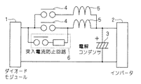
そこで、本実施の形態に係るインバータ装置では、図1に示す回路図のように構成することで、必要とされる電流容量を確保している。図1に示すインバータ装置では、交流電源(図示せず)から入力された交流電圧を直流電圧に整流するダイオードモジュール1と、負荷(図示せず)を駆動するインバータ2と、ダイオードモジュール1とインバータ2との間で直流電圧が供給される直流部とで構成されている。
Therefore, the inverter device according to the present embodiment is configured as shown in the circuit diagram of FIG. 1 to ensure the required current capacity. In the inverter device shown in FIG. 1, a
図1に示す直流部は、ダイオードモジュール1で整流された直流電圧で充電されるコンデンサ3と、ダイオードモジュール1とコンデンサ3との接続を制御するリレー4と、リレー4とコンデンサ3との間に直列接続されたリアクタ5とが設けられている。さらに、図1に示す直流部では、リレー4とリアクタ5との組合せが2つ並列して設けられている。
The DC unit shown in FIG. 1 includes a
なお、図1に示すインバータ装置には、リレー4と並列接続する形で突入電流防止回路6を設けている。この突入電流防止回路6は、リレー回路や抵抗等で構成され、インバータ2に突入電流が供給されることを防止している。
In addition, the inrush
また、ダイオードモジュール1は、図示していないが複数のダイオードを備え、入力する交流電圧を全波整流して、直流部の配線に直流電圧として供給する。コンデンサ3は、平滑コンデンサであり、ダイオードモジュール1からの直流電圧を平滑してインバータ2に出力する。インバータ2は、IGBT(insulated gate bipolar transistor)等の半導体スイッチを複数備え、当該半導体スイッチのスイッチングを制御することで任意の3相交流を生成し、負荷であるモータ等を駆動する。
The
次に、図1に示すインバータ装置では、二つのリレー4のそれぞれにリアクタ5を直列に接続し、直列接続されたリレー4とリアクタ5との組合せ(以下、単に「組合せ」と称す)が、相互に並列に接続されている。そのため、図1に示すインバータ装置は、リレー4間での接点抵抗のバラツキをリアクタ5の抵抗で吸収し、組合せが並列接続された全体としての電流容量をより多く確保できる。
Next, in the inverter device shown in FIG. 1, the
図7及び図8を用いて具体的に説明する。まず、図1に示したリレー4の接点抵抗は1mΩ程度で、異なるリレー4間での接点抵抗のバラツキは100%であるとする。そのため、図7に示すリレー4のうち一方のリレー4aが接点抵抗を1mΩとすると、他方のリレー4bの接点抵抗が2mΩとなる場合が考えられる。この場合、図7に示すようにリレー4aに流れる電流は40Aのうち26.7Aが流れ、他方のリレー4bに流れる電流(13.3A)の約2倍となる。
This will be specifically described with reference to FIGS. First, the contact resistance of the
しかし、本実施の形態に係るインバータ装置では、図8(a)に示すようにリレー4aにリアクタ5aを直列接続し、且つリレー4bにリアクタ5bを直列接続している。このリアクタ5a,5bの直流抵抗は、リレー4a,4bの接点抵抗に比べて十分大きく、例えば20mΩ程度ある。そして、リアクタ5a,5b間の直流抵抗のバラツキは小さく10%程度である。そのため、一方のリレー4aに直列接続されるリアクタ5aの直列抵抗を20mΩ、他方のリレー4bに直列接続されるリアクタ5bの直列抵抗を22mΩとすると、一方のリレー4aとリアクタ5aとの組合せによる抵抗値は1+20=21mΩ、他方のリレー4bとリアクタ5bとの組合せによる抵抗値は2+22=24mΩとなる。よって、図8(a)に示すように、リレー4aに流れる電流は40Aのうち18.7Aが流れ、他方のリレー4bに21.3Aの電流が流れることになるため、リレー4a,4b間の電流のアンバランスを図7の場合に比べて小さくできる。さらに、リレー4a,4bがそれぞれ20Aまでしか流せないリレーであれば、図8(b)のようにリレー4bに流れる電流が20Aとなるようにリレー4a,4b全体に流す電流を37.6A程度に抑える。
However, in the inverter device according to the present embodiment, as shown in FIG. 8A, the
従って、一方のリレー4aとリアクタ5aとの組合せと、他方のリレー4bとリアクタ5bとの組合せとの抵抗のバラツキは20%程度に抑えることができる。つまり、リレー4a,4bのそれぞれにリアクタ5a,5bを直列接続することで接点抵抗のバラツキを抑え、リレー4a,4b間の電流のアンバランスを小さくしている。リレー4a,4b間の電流のアンバランスを小さくすることで、リレー4a,4bを並列にすることによる電流容量の拡大が可能となる。具体的に、電流容量が20Aのリレー4a,4bを図7のように単純に2つ並列にした場合、25A程度しか電流容量を確保できなかったものが、図8(b)のように構成することで37.6A程度の電流容量を確保できる。そのため、安価で小型である電流容量の小さい(20A程度)リレー4を複数用いて、より大きい電流容量を確保できる。
Therefore, the variation in resistance between the combination of one
また、図1に示すようにリレー4のそれぞれにリアクタ5を直列接続するため、1つのリアクタ5に流れる電流を小さくすることができる。例えば、電流容量の大きい1つのリレー4に当該電流容量に見合うリアクタ5を1つ設ける場合や、電流容量の小さいリレー4を複数並列して、当該複数のリレー4に対して1つのリアクタ5を設ける場合に比べて1つのリアクタ5に流れる電流を小さくすることができる。リアクタ5に流れる電流を小さくできれば、リアクタ5自体を小型化でき、安価となる。
Further, since the
なお、本実施の形態に係るインバータ装置では、リレー4とリアクタ5との直列接続した組合せを2つ並列した例を説明したが、本発明はこれに限られず、3つ以上を並列した構成であっても良い。
In the inverter device according to the present embodiment, an example in which two series-connected combinations of the
(実施の形態2)
現在市販されているリレーには、複数の接点を1つのパッケージングしたものがある。このパッケージングしたリレー(以下、リレー回路ともいう)を利用して、図1に示すインバータ装置を構成すると、図2に示す回路構成となる。
(Embodiment 2)
Some relays currently on the market have a plurality of contacts in one package. When the packaged relay (hereinafter also referred to as a relay circuit) is used to configure the inverter device shown in FIG. 1, the circuit configuration shown in FIG. 2 is obtained.
図2に示すインバータ装置では、2つの接点をもつリレー回路40を用いている。このリレー回路40のそれぞれの接点をそれぞれリレー4として取り扱い、当該接点と、リアクタ5とを直列接続して、リレー4とリアクタ5との直列接続した組合せを2つ並列したインバータ装置を構成している。なお、図2に示すインバータ装置は、並列する2つのリレー4をリレー回路40に置き換えた以外は、図1に示すインバータ装置と同じ構成であるため、同一の符号を付して詳細な説明を省略する。
In the inverter device shown in FIG. 2, a
図2に示すインバータ装置のように、並列する2つのリレー4をリレー回路40に置き換えることで、個別のリレー4を基板に実装するよりも小型化できる利点を有している。さらに、個別のリレー4における接点抵抗のバラツキよりも、1つにパッケージングされたリレー回路40におけるリレー4それぞれの接点抵抗のバラツキの方が小さいので、リレー回路40を用いる図2に示すインバータ装置の方がより大きい電流容量を確保することができる利点を有している。
As in the inverter device shown in FIG. 2, by replacing the two
またリレー4を動作させるための電流供給も一つで足りる。
One current supply is sufficient to operate the
なお、図2に示すインバータ装置では、2つの接点をもつリレー回路40を用いる例を示したが、本発明はこれに限られず、3つの接点をもつリレー回路40を用いて、リレー4とリアクタ5との直列接続した組合せを3つ以上並列した構成でも良い。
2 shows an example in which the
(変形例)
さらに、本実施の形態に係るインバータ装置の変形例の回路図を図3に示す。図3に示すインバータ装置では、図1に示すインバータ装置のリレー4のそれぞれに、2つの接点を有するリレー回路を採用している。つまり、図3に示すリレー4は、接点4aと接点4bとが並列接続されたリレー回路で構成される。この2つの接点4a,4bを有するリレー4のそれぞれに対してリアクタ5が直列接続され、当該リレー4とリアクタ5との組合せが2つ並列した構成が図3に示すインバータ装置である。
(Modification)
Furthermore, a circuit diagram of a modification of the inverter device according to the present embodiment is shown in FIG. In the inverter device shown in FIG. 3, a relay circuit having two contacts is employed for each
接点4a及び接点4bにはそれぞれリアクタ5を接続しないため、両接点4a,4bの接点抵抗のバラツキは吸収されないので、両接点4a,4bを並列にした場合、いずれか1つの接点に電流が集中し、多くの電流容量を確保することはできない。しかし、2つの接点を並列にしたリレー4は、少なくとも1つの接点を有するリレー4に比べると電流容量は増加する。そのため、図1に示すインバータ装置のように、それぞれのリレー4が1つの接点を有する場合に比べて、図3に示すインバータ装置のように、それぞれのリレー4が2つの接点を有する場合の方が、より大きい電流容量を確保することができる。
Since the
また、2つの接点を有するリレー4を採用することで、1つの接点が故障したとしても装置全体としての動作には影響を与えないため、本変形例に係るインバータ装置はより信頼性の高い装置となる。
Further, by adopting the
なお、図3に示すインバータ装置では、2つの接点をもつリレー4を用いる例を示したが、本発明はこれに限られず、3つ以上の接点をもつリレー4を用いても良い。また、図3に示すインバータ装置では、2つの接点をもつリレー4とリアクタ5との直列接続した組合せを2つ並列した構成を示したが、本発明はこれに限られず、複数の接点をもつリレー4とリアクタ5との直列接続した組合せを3つ以上並列した構成でも良い。
In addition, although the example which uses the
さらに、本実施の形態及び変形例に係るインバータ装置では、インバータ2の半導体スイッチをOFFにして負荷に流れる電流を止めた状態にしてからリレー4のON・OFFの制御を行っている。
Further, in the inverter device according to the present embodiment and the modification, the
(実施の形態3)
実施の形態1,2に係るインバータ装置では、ダイオードモジュール1で整流された直流電圧が供給される直流部に、リレー4を設ける構成について説明したが、本発明はこれに限られない。本実施の形態に係るインバータ装置は、図4に示すようにダイオードモジュール1に交流電圧を供給する部分(以下、単に交流部ともいう)にリレー4を設ける構成である。
(Embodiment 3)
In the inverter devices according to the first and second embodiments, the configuration in which the
図4に示すインバータ装置は、交流部にリレー4とリアクタ5との直列接続した組合せを2つ並列した構成を備えている。一方、図4に示すインバータ装置の直流部には、図1等に示すインバータ装置と異なりリレー4等を設けていない。なお、図4に示すインバータ装置は、リレー4及びリアクタ5の配置以外は、図1に示すインバータ装置と同じ構成であるため、同一の符号を付して詳細な説明を省略する。
The inverter device shown in FIG. 4 includes a configuration in which two combinations of a
図4に示すインバータ装置でも、図1に示すインバータ装置と同様に、リレー4とリアクタ5との直列接続した組合せを2つ並列することで、より大きい電流容量を確保することができる。
Also in the inverter device shown in FIG. 4, as in the inverter device shown in FIG. 1, a larger current capacity can be ensured by paralleling two combinations of the
なお、図4に示すインバータ装置では、交流部に1つの接点をもつリレー4を用いる例を示したが、本発明はこれに限られず、2つ以上の接点をもつリレー4を用いても良い。また、図4に示すインバータ装置では、交流部にリレー4とリアクタ5との直列接続した組合せを2つ並列した構成を示したが、本発明はこれに限られず、リレー4とリアクタ5との直列接続した組合せを3つ以上並列した構成でも良い。
In the inverter device shown in FIG. 4, the example in which the
(実施の形態4)
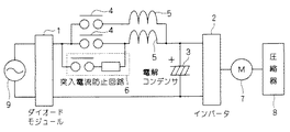
実施の形態1乃至3に係るインバータ装置は、空調機に用いることができる。具体的に、実施の形態1に係るインバータ装置を空調機に用いた場合は説明する。図5は、図1に示すインバータ装置を用いた空調機の回路ブロック図である。
(Embodiment 4)
The inverter device according to
図5に示す空調機では、図1に示すインバータ装置の構成に加えて、インバータ2により駆動されるモータ7と、モータ7により駆動されることで冷媒を圧縮する圧縮器8と、ダイオードモジュール1に交流電圧を供給する交流電源9とを備えている。
In the air conditioner shown in FIG. 5, in addition to the configuration of the inverter device shown in FIG. 1, the motor 7 driven by the
図5に示す空調機のように図1に示すインバータ装置を採用することで、必要な電流容量を確保しつつ、空調機全体も小型化、低コスト化できる。 By adopting the inverter device shown in FIG. 1 like the air conditioner shown in FIG. 5, the entire air conditioner can be reduced in size and cost while ensuring the necessary current capacity.
1 ダイオードモジュール
2 インバータ
3 コンデンサ
4 リレー
5 リアクタ
6 突入電流防止回路
7 モータ
8 圧縮器
9 交流電源
40 リレー回路
1
Claims (4)
前記ダイオードモジュール(1)への前記交流電圧の入力を制御するリレー(4)と、
前記リレー(4)とダイオードモジュール(1)との間に直列接続されたリアクタ(5)と、
前記ダイオードモジュール(1)で整流された前記直流電圧で充電されるコンデンサ(3)と、
前記コンデンサ(3)の両端電圧に基づき負荷を駆動するインバータ(2)とを備え、
前記リレーの開閉状態によらず、直列接続された前記リレー(4)と前記リアクタ(5)との組合せが複数並列して設けられているインバータ装置。 A diode module (1) for rectifying the input AC voltage into a DC voltage;
A relay (4) for controlling the input of the AC voltage to the diode module (1) ;
A series-connected reactors (5) between the front SL relay (4) and the diode module (1),
A capacitor (3) charged with the DC voltage rectified by the diode module (1);
An inverter (2) for driving a load based on the voltage across the capacitor (3),
An inverter device in which a plurality of combinations of the relay (4) and the reactor (5) connected in series are provided in parallel regardless of the open / closed state of the relay.
複数並列に設けられた前記リレー(4)が一体として形成されているインバータ装置。 The inverter device according to claim 1,
An inverter device in which a plurality of the relays (4) provided in parallel are integrally formed .
前記リレー(4)のそれぞれが、複数の接点を有しているインバータ装置。 The inverter device according to claim 1 or claim 2,
An inverter device in which each of the relays (4) has a plurality of contacts .
前記インバータ装置により駆動される前記負荷である電動機(7)と、
前記電動機(7)の動作により冷媒の圧縮を行う圧縮機(8)とを備える空調機。 An inverter apparatus according to any one of claims 1 to 3,
An electric motor (7) as the load driven by the inverter device;
An air conditioner comprising a compressor (8) that compresses refrigerant by an operation of the electric motor (7) .
Priority Applications (1)
| Application Number | Priority Date | Filing Date | Title |
|---|---|---|---|
| JP2008278303A JP5560552B2 (en) | 2008-10-29 | 2008-10-29 | Inverter device and air conditioner using the same |
Applications Claiming Priority (1)
| Application Number | Priority Date | Filing Date | Title |
|---|---|---|---|
| JP2008278303A JP5560552B2 (en) | 2008-10-29 | 2008-10-29 | Inverter device and air conditioner using the same |
Publications (2)
| Publication Number | Publication Date |
|---|---|
| JP2010110085A JP2010110085A (en) | 2010-05-13 |
| JP5560552B2 true JP5560552B2 (en) | 2014-07-30 |
Family
ID=42298977
Family Applications (1)
| Application Number | Title | Priority Date | Filing Date |
|---|---|---|---|
| JP2008278303A Active JP5560552B2 (en) | 2008-10-29 | 2008-10-29 | Inverter device and air conditioner using the same |
Country Status (1)
| Country | Link |
|---|---|
| JP (1) | JP5560552B2 (en) |
Families Citing this family (3)
| Publication number | Priority date | Publication date | Assignee | Title |
|---|---|---|---|---|
| JP5814841B2 (en) * | 2012-03-23 | 2015-11-17 | 株式会社日立産機システム | Power converter |
| US9614456B2 (en) | 2012-11-20 | 2017-04-04 | Mitsubishi Electric Corporation | Power conversion apparatus that prevents inrush current and air-conditioning apparatus using the same |
| EP2942862B1 (en) | 2013-01-07 | 2020-08-19 | Mitsubishi Electric Corporation | Electric power conversion device and air conditioning device using same |
Family Cites Families (7)
| Publication number | Priority date | Publication date | Assignee | Title |
|---|---|---|---|---|
| JPH0674535A (en) * | 1992-08-26 | 1994-03-15 | Hitachi Ltd | Air conditioner |
| JPH06303717A (en) * | 1993-04-09 | 1994-10-28 | Meidensha Corp | Automatic inspection system of protective relay device |
| JPH08126324A (en) * | 1994-10-28 | 1996-05-17 | Japan Steel Works Ltd:The | Converter circuit |
| JP3757745B2 (en) * | 2000-03-30 | 2006-03-22 | ダイキン工業株式会社 | Preheating power control method and preheating generation mechanism |
| JP2002095257A (en) * | 2000-09-13 | 2002-03-29 | Sony Corp | Power supply for electronic equipment |
| US6608770B2 (en) * | 2001-08-31 | 2003-08-19 | Vlt Corporation | Passive control of harmonic current drawn from an AC input by rectification circuitry |
| JP2008206280A (en) * | 2007-02-20 | 2008-09-04 | Yaskawa Electric Corp | Power converter |
-
2008
- 2008-10-29 JP JP2008278303A patent/JP5560552B2/en active Active
Also Published As
| Publication number | Publication date |
|---|---|
| JP2010110085A (en) | 2010-05-13 |
Similar Documents
| Publication | Publication Date | Title |
|---|---|---|
| JP5212303B2 (en) | Power converter | |
| JP6111520B2 (en) | Power converter | |
| CN103534920B (en) | Power conversion circuit and air conditioner | |
| JP5822792B2 (en) | Power supply circuit and air conditioner having the same | |
| CN104205602B (en) | Rectification circuit | |
| JP2011004449A (en) | Matrix converter circuit | |
| CN109863685B (en) | Air conditioner and drive device | |
| JP5660916B2 (en) | Power converter and air conditioner | |
| EP2768131B1 (en) | Inverter device | |
| JP2012165509A (en) | Inrush current prevention circuit for power supply apparatus | |
| WO2015098937A1 (en) | Overvoltage protection circuit and power conversion device provided therewith | |
| CN106463995A (en) | Power supplies for electrical appliances, especially battery chargers for charging electric vehicle batteries | |
| US10020768B2 (en) | Driving apparatus for an electric motor, a method for actuation thereof and a motor unit which comprises the driving apparatus | |
| JP5560552B2 (en) | Inverter device and air conditioner using the same | |
| WO2013099098A1 (en) | Converter circuit | |
| CN109756136B (en) | Switching power supply | |
| JP2014171370A (en) | Motor drive control device, air conditioner, ventilation fan, and heat pump type hot-water supplier | |
| JP6466023B2 (en) | Air conditioner | |
| JP6468114B2 (en) | Power supply device and switch control method thereof | |
| JP2014050166A (en) | Dc power supply | |
| JP5948706B2 (en) | Switch device | |
| CN103380338B (en) | Power circuit and heat pump unit | |
| CN105830302B (en) | Overvoltage protection circuit and power conversion device having the overvoltage protection circuit | |
| JP6690777B2 (en) | Main converter circuit, power converter and mobile unit | |
| JP2017215068A (en) | Power supply device and air conditioner |
Legal Events
| Date | Code | Title | Description |
|---|---|---|---|
| A621 | Written request for application examination |
Free format text: JAPANESE INTERMEDIATE CODE: A621 Effective date: 20110811 |
|
| A977 | Report on retrieval |
Free format text: JAPANESE INTERMEDIATE CODE: A971007 Effective date: 20130111 |
|
| A131 | Notification of reasons for refusal |
Free format text: JAPANESE INTERMEDIATE CODE: A131 Effective date: 20130122 |
|
| A521 | Written amendment |
Free format text: JAPANESE INTERMEDIATE CODE: A523 Effective date: 20130305 |
|
| A131 | Notification of reasons for refusal |
Free format text: JAPANESE INTERMEDIATE CODE: A131 Effective date: 20130903 |
|
| A521 | Written amendment |
Free format text: JAPANESE INTERMEDIATE CODE: A523 Effective date: 20131025 |
|
| A131 | Notification of reasons for refusal |
Free format text: JAPANESE INTERMEDIATE CODE: A131 Effective date: 20140304 |
|
| A521 | Written amendment |
Free format text: JAPANESE INTERMEDIATE CODE: A523 Effective date: 20140422 |
|
| TRDD | Decision of grant or rejection written | ||
| A01 | Written decision to grant a patent or to grant a registration (utility model) |
Free format text: JAPANESE INTERMEDIATE CODE: A01 Effective date: 20140513 |
|
| A61 | First payment of annual fees (during grant procedure) |
Free format text: JAPANESE INTERMEDIATE CODE: A61 Effective date: 20140526 |
|
| R151 | Written notification of patent or utility model registration |
Ref document number: 5560552 Country of ref document: JP Free format text: JAPANESE INTERMEDIATE CODE: R151 |