JP5557166B2 - Protective fence - Google Patents
Protective fence Download PDFInfo
- Publication number
- JP5557166B2 JP5557166B2 JP2011098542A JP2011098542A JP5557166B2 JP 5557166 B2 JP5557166 B2 JP 5557166B2 JP 2011098542 A JP2011098542 A JP 2011098542A JP 2011098542 A JP2011098542 A JP 2011098542A JP 5557166 B2 JP5557166 B2 JP 5557166B2
- Authority
- JP
- Japan
- Prior art keywords
- prevention structure
- horizontal rope
- falling
- rock
- wire
- Prior art date
- Legal status (The legal status is an assumption and is not a legal conclusion. Google has not performed a legal analysis and makes no representation as to the accuracy of the status listed.)
- Active
Links
- 230000001681 protective effect Effects 0.000 title claims description 49
- 239000000463 material Substances 0.000 claims description 81
- 230000002265 prevention Effects 0.000 claims description 73
- 238000009434 installation Methods 0.000 claims description 29
- 230000004888 barrier function Effects 0.000 claims 2
- 239000011435 rock Substances 0.000 description 113
- 238000000034 method Methods 0.000 description 10
- 229910000831 Steel Inorganic materials 0.000 description 8
- 239000010959 steel Substances 0.000 description 8
- 239000004575 stone Substances 0.000 description 8
- 230000000694 effects Effects 0.000 description 6
- 230000035939 shock Effects 0.000 description 6
- 239000002184 metal Substances 0.000 description 4
- 239000002689 soil Substances 0.000 description 4
- 239000006096 absorbing agent Substances 0.000 description 3
- 239000004570 mortar (masonry) Substances 0.000 description 3
- 230000009471 action Effects 0.000 description 2
- 230000008878 coupling Effects 0.000 description 2
- 238000010168 coupling process Methods 0.000 description 2
- 238000005859 coupling reaction Methods 0.000 description 2
- 230000000630 rising effect Effects 0.000 description 2
- 239000004576 sand Substances 0.000 description 2
- 239000002023 wood Substances 0.000 description 2
- 235000014036 Castanea Nutrition 0.000 description 1
- 241001070941 Castanea Species 0.000 description 1
- 238000009825 accumulation Methods 0.000 description 1
- 230000008859 change Effects 0.000 description 1
- 239000004744 fabric Substances 0.000 description 1
- 238000009415 formwork Methods 0.000 description 1
- JEIPFZHSYJVQDO-UHFFFAOYSA-N iron(III) oxide Inorganic materials O=[Fe]O[Fe]=O JEIPFZHSYJVQDO-UHFFFAOYSA-N 0.000 description 1
- 230000004048 modification Effects 0.000 description 1
- 238000012986 modification Methods 0.000 description 1
- 230000003449 preventive effect Effects 0.000 description 1
- 230000008439 repair process Effects 0.000 description 1
- 238000005096 rolling process Methods 0.000 description 1
- 239000013049 sediment Substances 0.000 description 1
- 239000012209 synthetic fiber Substances 0.000 description 1
- 229920002994 synthetic fiber Polymers 0.000 description 1
- 238000003466 welding Methods 0.000 description 1
- 239000002759 woven fabric Substances 0.000 description 1
Images


Landscapes
- Devices Affording Protection Of Roads Or Walls For Sound Insulation (AREA)
Description
本発明は、雪崩・落石等における防護柵に関する。 The present invention relates to a protective fence for avalanches, falling rocks and the like.
従来、この種の防護柵として、地上に間隔を置き建て込んだ端末パイプ支柱及び中間パイプ支柱に複数段のケーブルとともに金網を張設したものや、適宜の間隔を置き建て込んだH型鋼の端末支柱及び中間支柱と、これら支柱間に張設した複数段のケーブル及び金網とを備えた防護柵(例えば特許文献1)が知られている。
Conventionally, as this kind of protective fence, terminal pipe struts built on the ground at intervals and intermediate pipe struts with wire mesh stretched together with multiple stages of cables, and H-shaped steel terminals built at
また、ロープ材を保持する保持解除装置を備え、この保持解除装置は、常時または積雪の雪圧のような長期間にわたって作用する比較的小さい横力に対しては、中間ロープ材を中間支柱に保持した状態を維持し、かつ落石が衝突した時のような雪圧より大きい横力が作用した場合には中間ロープ材の保持を解除して中間ロープ材を落石等の衝突物の進入側と反対側に向けた大きな移動を許容する防護柵(例えば特許文献2)がある。 In addition, a holding release device for holding the rope material is provided, and this holding release device is used for the intermediate rope material as an intermediate strut for a relatively small lateral force that acts constantly or for a long time such as snow pressure of snow. When the holding force is maintained and a lateral force greater than snow pressure is applied, such as when a falling rock collides, the holding of the intermediate rope material is released and the intermediate rope material is moved away from the collision object such as falling rock. There is a protective fence (for example, Patent Document 2) that allows a large movement toward the opposite side.
また、支柱間に設ける横ロープ材を把持し、該横ロープ材に加わる張力を横ロープ材の摩擦摺動により吸収するロープ用緩衝具(例えば特許文献3)が提案されており、この緩衝具はUボルトを備え、このUボルトを連結する連結部を、前記支柱に設けている。 Further, a rope shock absorber (for example, Patent Document 3) that holds a horizontal rope material provided between struts and absorbs the tension applied to the horizontal rope material by frictional sliding of the horizontal rope material has been proposed. Has a U-bolt, and a connecting portion for connecting the U-bolt is provided on the support column.
上記の様に支柱間にロープ材を複数段に設け、前記ロープ材の両端を端末支柱に固定し、中間支柱においてはスライドを許容する防護柵では、下方に落石を受けると、最下段のロープ材が捲れあがったりして落石が通過する虞がある。 As described above, rope material is provided in multiple stages between struts, and both ends of the rope material are fixed to the terminal struts. There is a risk that the fallen stones will pass due to the material rolling up.
また、中間支柱にロープ用緩衝具により横ロープ材を連結するものでも、横ロープ材が緩衝具に摩擦摺動すると、横ロープ材が撓むため、同様に落石が通過する虞がある。 Moreover, even if the horizontal rope member is connected to the intermediate strut by the rope shock absorber, when the horizontal rope member frictionally slides on the shock absorber, the horizontal rope material is bent, and there is a possibility that the falling rocks may similarly pass.
そこで本発明は上述した問題点に鑑み、支柱下段における落石の通過を防止することができる防護柵を提供することを目的とする。 In view of the above-described problems, an object of the present invention is to provide a protective fence that can prevent the falling rocks from passing through the lower stage of the column.
また、支柱下段における落石の通過を防止しつつ、支柱下段における横ロープ材や金網で構成された防護面での落石の衝撃を緩和することができる防護柵を提供することを目的とする。 It is another object of the present invention to provide a protective fence that can mitigate the impact of falling rocks on a protective surface composed of a horizontal rope material and a wire net in the lower column of the column while preventing the falling rocks from passing through the column.
上記目的を達成するために、請求項1に係る発明は、設置面に左右に所定の間隔で複数の支柱を設け、前記支柱間に横ロープ材を多段に設けた防護柵において、前記設置面と下段の前記横ロープ材間を塞ぐ遮蔽部材を備え、前記遮蔽部材が、前記支柱の設置場所の斜面側前方が薄く後方が厚い傾斜を有する傾斜部を設けた抜け出し防止構造であることを特徴とする。
To achieve the above object, the invention according to
また、請求項2に係る発明は、前記抜け出し防止構造が蛇籠であることを特徴とする。
The invention according to
また、請求項3に係る発明は、前記支柱に前記抜け出し防止構造を固定することを特徴とする。
The invention according to
また、請求項4に係る発明は、前記設置面に前記抜け出し防止構造を固定することを特徴とする。
The invention according to
また、請求項5に係る発明は、前記支柱を支える控えワイヤと、前記控えワイヤを固定する控ワイヤ用アンカーを設けた防護柵において、前記控ワイヤ用アンカーより前記抜け出し防止構造を吊るすことを特徴とする。
The invention according to
また、請求項6に係る発明は、前記横ロープ材と金網で構成された防護面を設けた防護柵において、前記防護面に前記抜け出し防止構造を固定することを特徴とする。
The invention according to
また、請求項7に係る発明は、前記抜け出し防止構造が、前記横ロープ材に連結された袋体であることを特徴とする。
The invention according to
本発明の請求項1の構成によれば、落石により設置面と横ロープ材との間を落石が通過することを防止できる。また、落石が発生し抜け出し防止構造の傾斜部に落石が衝突した際、傾斜部の傾斜は山側である斜面側前方が薄く反山側である後方が厚い構成になっているので、落石の進行方向が上方向に誘導され、抜け出し防止構造により落石を適切に上方に導くことで、落石防護柵の設置面と横ロープ材との間を落石が通過することを防止でき、それに加えて横ロープ材や金網で構成された防護面は落石の衝撃を直接受けないので、防護面での落石の衝撃を緩和できる。
According to the structure of
また、本発明の請求項2の構成によれば、設置面と横ロープ材との間を落石が通過することを防止できると共に、蛇籠により落石の衝撃を吸収するので支柱下段における横ロープ材や金網で構成された防護面での落石の衝撃を緩和できる。 Further, according to the second aspect of the present invention, the horizontal rope materials in post lower with between setting surface and the horizontal rope materials can be prevented from passing through the falling rocks, because it absorbs the impact of the falling rock by gabion The impact of falling rocks on the protective surface made of metal mesh can be mitigated .
また本発明の請求項3の構成によれば、落石の衝突する際の衝撃で抜け出し防止構造の位置や傾斜部の傾斜角度がずれることがない。そのため、より確実に抜け出し防止構造により落石防護柵の設置面と横ロープ材との間を落石が通過することを防止でき、それに加えてより確実に横ロープ材や金網で構成された防護面での落石の衝撃を緩和できる。 According to the third aspect of the or invention, is never deviated inclination angle position and the inclined portion of the preventive structure coming off the impact when collision rock fall. For this reason, it is possible to prevent falling rocks from passing between the installation surface of the falling rock protection fence and the horizontal rope material with a structure that prevents falling out more reliably, and in addition to that, a protective surface made up of horizontal rope material and wire mesh more reliably. Can reduce the impact of falling rocks.
また本発明の請求項4の構成によれば、落石の衝突する際の衝撃で抜け出し防止構造の位置や傾斜部の傾斜角度がずれることがない。そのため、より確実に抜け出し防止構造により落石防護柵の設置面と横ロープ材との間を落石が通過することを防止でき、それに加えてより確実に横ロープ材や金網で構成された防護面での落石の衝撃を緩和できる。 Further, according to the configuration of the fourth aspect of the present invention, the position of the slip-out prevention structure and the inclination angle of the inclined portion are not shifted due to an impact when a falling rock collides. For this reason, it is possible to prevent falling rocks from passing between the installation surface of the falling rock protection fence and the horizontal rope material with a structure that prevents falling out more reliably, and in addition to that, a protective surface made up of horizontal rope material and wire mesh more reliably. Can reduce the impact of falling rocks.
また本発明の請求項5の構成によれば、落石の衝突する際の衝撃で抜け出し防止構造の位置や傾斜部の傾斜角度がずれることがない。そのため、より確実に抜け出し防止構造により落石防護柵の設置面と横ロープ材との間を落石が通過することを防止でき、それに加えてより確実に横ロープ材や金網で構成された防護面での落石の衝撃を緩和できる。 Further, according to the configuration of the fifth aspect of the present invention, the position of the slip-out prevention structure and the inclination angle of the inclined portion are not shifted due to an impact when a falling rock collides. For this reason, it is possible to prevent falling rocks from passing between the installation surface of the falling rock protection fence and the horizontal rope material with a structure that prevents falling out more reliably, and in addition to that, a protective surface made up of horizontal rope material and wire mesh more reliably. Can reduce the impact of falling rocks.
また本発明の請求項6の構成によれば、落石の衝突する際の衝撃で抜け出し防止構造の位置や傾斜部の傾斜角度がずれることがない。そのため、より確実に抜け出し防止構造により落石防護柵の設置面と横ロープ材との間を落石が通過することを防止でき、それに加えてより確実に横ロープ材や金網で構成された防護面での落石の衝撃を緩和できる。 According to the configuration of the sixth aspect of the present invention, the position of the slip-out prevention structure and the inclination angle of the inclined portion are not shifted due to an impact when a falling rock collides. For this reason, it is possible to prevent falling rocks from passing between the installation surface of the falling rock protection fence and the horizontal rope material with a structure that prevents falling out more reliably, and in addition to that, a protective surface made up of horizontal rope material and wire mesh more reliably. Can reduce the impact of falling rocks.
また、本発明の請求項7の構成によれば、設置面と横ロープ材との間を落石が通過することを防止できると共に、袋体により落石の衝撃を吸収するので支柱下段における横ロープ材や金網で構成された防護面での落石の衝撃を緩和できる。
Moreover, according to the structure of
以下、図面を参照して、本発明の防護柵の参考例1について説明する。
(参考例1)
Hereinafter, a reference example 1 of the protective fence of the present invention will be described with reference to the drawings.
(Reference Example 1)
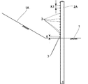
図1〜図7に示す様に、衝撃吸収柵である落石防護柵は設置場所である斜面1A下部の地面1に複数の支柱2,2A,2A,2が略垂直に立設されている。尚、端末支柱2,2の間に複数の中間支柱2A,2Aが配置されている。前記支柱2,2Aは、H型鋼,コンクリート柱,鋼管あるいはコンクリート充填鋼管などからなり、この例では鋼管を用い、その下端を前記地面1に建て込んで固定している。
As shown in FIG. 1 to FIG. 7, a rockfall protection fence, which is an impact absorbing fence, has a plurality of
前記支柱2,2A,2A,2間には横ロープ材3,3が上下段に設けられている。また、支柱2,2A,2A,2の間は金網9により遮蔽されている。また、金網9はバンド線などの結合材により横ロープ材3,7に結合されている。また、横ロープ材3,7を縦方向の間隔保持材10にそれぞれ係止し、この間隔保持材10により落石が衝突した場合でも、上下のロープ材の間隔が開いて落石が通過しない様になっている。尚、支柱2,2A,2A,2は上記の様に下部を地中に建て込んで固定してもよいし、コンクリート基礎等に固定してもよいし、下部を斜面などに位置固定すると共に、山側と谷側の控えロープ材により固定してもよい。また中間支柱2Aには、前記ロープ材3を係止する係止部4が設けられ、前記係止部4は横ロープ材3を係止する係止用フックなどにより構成され、横ロープ材3の長さ方向の移動を許容する。
Between the said support |
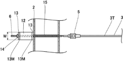
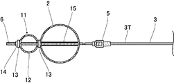
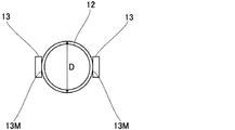
前記横ロープ材3は、その両端を前記端末支柱2に連結し、その途中を前記中間の支柱2Aに横方向移動可能に係止している。具体的には、前記横ロープ材3の端部3Tに連結具5により横杆6を連結し、この横杆6を衝撃吸収装置11により前記端末支柱2に連結している。図3〜図5に示す様に、前記衝撃吸収装置11は鋼管などからなるリング材12と、このリング材12を外周両側から挟むように配置される載荷部材たる載荷板13,13と、それら載荷板13,支柱2,リング材12及び載荷板13に挿通する前記横杆6と、この横杆6に設ける端末定着具たるナット14とを備え、前記横杆6にはナット14を螺合する雄ねじ部が形成されている。尚、前記載荷板13,13のリング材12の外周に当接する側の面が、載荷面13M,13Mであり、前記載荷面13Mは前記リング材12の長さ方向の幅とほぼ同一の幅を有し、又は大きな幅を有し、一方リング材12の直径方向の幅Wは、該リング材12の直径D寸法より小さい。また、前記リング材12はその中心軸を縦方向に向けているから、上下にスペースを取らずに配置することができる。また前記端末支柱2内には前記横杆6を挿通する管材15が設けられ、この管材15には鋼管などが用いられ、その管材15の端部を溶接などにより端末支柱2に固着している。
Both ends of the
そして、横ロープ材3に引張力が発生し、ナット14が支柱2側に移動すると、載荷面13M,13Mによりリング材12が押し潰され、これにより衝撃エネルギーを吸収し、対向する内面が当接するまでリング材12が潰れた後は、横ロープ材3が伸びることにより衝撃エネルギーを吸収することができる。
Then, when a tensile force is generated in the
前記支柱2,2A,2A,2の下段には横ロープ材7が2段に設けられ、前記横ロープ材7の両端は端末支柱2,2に固定されている。図1に示した様に、下段の前記横ロープ材7,7の間隔Kは上段側で上下に隣合う前記横ロープ材3,3の間隔K1より同等または狭く設定されている(K=<K1)。また最下段の横ロープ材7は、前記間隔Kより狭い間隔で地面1と近接して配置されている。
Two
前記横ロープ材7の両端は前記衝撃吸収装置11により端末支柱2,2に連結されたり、固定状態で連結される。また、前記横ロープ材7の中央は前記係止部4などにより中間支柱2Aに係止されている。
Both ends of the
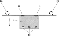
図6及び図7に示す様に、前記防護柵は前記下段の横ロープ材7,7間を遮蔽する遮蔽部材を備える。前記遮蔽部材にはジオグリッドやワイヤーネットなどの網状体51が用いられ、支柱2,2A,2A,2の中央において、前記横ロープ材7,7とこの上段の横ロープ材3に前記網状体51の一側を結合コイルなどの連結具52により連結し、前記網状体51の他側を前記地面1に敷設すると共に、他側端部を複数の固定用アンカー53により地面1又は斜面1Aに固定する。尚、網状体51の上部は横ロープ材7の上の横ロープ材3に連結されており、この横ロープ材3の上の横ロープ材3より下である。
As shown in FIGS. 6 and 7, the protective fence includes a shielding member that shields between the lower
この様に本参考例では、設置面たる地面1に左右に所定の間隔で複数の支柱2,2A,2を設け、支柱2,2A,2間に横ロープ材3,7を多段に設けた防護柵において、地面1と下段の横ロープ材7,7間を塞ぐ遮蔽部材たる網状体51を備えるから、地面1と下段の横ロープ材7との間を落石が通過することを防止できる。
In the present embodiment in this manner, setting
また、この様に本参考例では、遮蔽部材が網状体51であり、この網状体51の一側を前記下段の横ロープ材7,7に連結すると共に、該網状体51の他側を支柱2,2A,2の設置場所の斜面側前方に固定したから、下段の横ロープ材7,7と網状体51とにより落石を捕捉すると共に、設置面と横ロープ材7との間を落石が通過することを防止できる。
Further, in this reference example In this manner, a shielding蔽部material like
また、参考例上の効果として、網状体51により横ロープ材7の捲り上がりを防止すると共に、可撓性を有する網状体51が変形することにより落石の衝撃を吸収することができる。
(参考例2)
In addition, as an effect on the reference example, the net 51 can prevent the
(Reference Example 2)
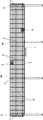
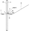
図8〜図9は本発明の参考例2を示し、上記参考例と同一部分に同一符号を付し、その詳細な説明を省略して詳述する。この例の遮蔽部材は鋼材などからなる線材枠61であり、この線材枠61は略L字型線材からなる枠材62と横線材63とを備え、その枠材62は前記横ロープ材7の前部に沿って設ける縦部62Tと前記横ロープ材7の前方の地面に設ける横部62Yとを有し、前記枠材62を横ロープ材7の長さ方向に略等間隔で複数配置し、その枠材62の縦部62Tと横部62Yに複数の前記横部材63を縦方向と前後方向に間隔をおいて一体に設けてなる。また縦部62Tにおける前記横部材63の上下間隔は、前記横ロープ材7の間隔より狭く、前記線材枠61は防護柵のほぼ全長に渡って設けられている。尚、線材枠61の上部は横ロープ材7の上の横ロープ材3に連結されており、この横ロープ材3の上の横ロープ材3より下である。
8 to 9 show a reference example 2 of the present invention, in which the same reference numerals are given to the same parts as in the reference example, and the detailed description thereof is omitted. The shielding member in this example is a
この様に本参考例では、遮蔽部材が線材枠61であり、この線材枠61は、下段の横ロープ材7,7の前面に沿って設けられると共に、左右方向に間隔をおいて設けられた複数の縦部62Tと、これら複数の縦部62Tに上下多段に設けた横部62Yとを備えるから、設置面と下段の横ロープ材7,7間を落石が通過することを防止できる。
In the present embodiment in this manner, a蔽部
また参考例上の効果として線状枠61を支柱2A,2A間の全長に設けたから、横ロープ材7の捲り上がりを一層効果的に防止することができる。
(参考例3)
Further, as an effect on the reference example, the
(Reference Example 3)
図10〜図11は本発明の参考例3を示し、上記各参考例と同一部分に同一符号を付し、その詳細な説明を省略して詳述する。この例の遮蔽部材は蛇籠71であり、網籠72に玉石や栗石を詰めてなる。また、蛇籠71の高さは、横ロープ材7の上の横ロープ材3の位置程度であり、この横ロープ材3の上の横ロープ材3より下である。
10 to 11 show a reference example 3 of the present invention. The same reference numerals are given to the same parts as those of the above-described reference examples, and detailed description thereof will be omitted. The shielding member in this example is a
この様に本参考例では、遮蔽部材が蛇籠71であるから蛇籠71により落石の衝撃を吸収すると共に、設置面と横ロープ材7との間を落石が通過することを防止できる。
(参考例4)
In the present embodiment in this manner, the shielding蔽部material absorbs the shock of falling rocks by
(Reference Example 4)
図12〜図13は本発明の参考例4を示し、上記各参考例と同一部分に同一符号を付し、その詳細な説明を省略して詳述する。この例の遮蔽部材は袋体81であり、袋82に砂,土,自然石,砕石などの土質材料あるいはモルタルコンクリートを詰めてなることが望ましいが、袋82に詰めるものはこれらに限定されるものではない。尚、袋体81は横ロープ材7や横ロープ材3に連結され、また袋体81の高さは横ロープ材7の上の横ロープ材3の位置程度であり、この横ロープ材3の上の横ロープ材3より下である。
12 to 13 show a reference example 4 of the present invention. The same reference numerals are given to the same parts as those of the above-mentioned reference examples, and detailed description thereof will be omitted. The shielding member in this example is a
この様に本参考例では、遮蔽部材が袋体81であるから袋体81により落石の衝撃を吸収すると共に、設置面と横ロープ材7との間を落石が通過することを防止できる。
In the present embodiment in this manner, the shielding蔽部material absorbs the shock of falling rocks by the
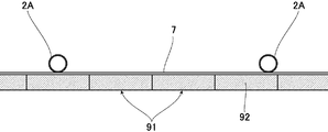
図14〜図17は本発明の実施例1を示し、上記各参考例と同一部分に同一符号を付し、その詳細な説明を省略して詳述する。この例の遮蔽部材は抜け出し防止構造91である。図15に示す様に、実施例1では抜け出し防止構造91は少なくても支柱2A,2Aの間隔以上の長さであるか、もしくは支柱2A,2Aの間隔以上の長さになるように連結されている。この時の連結方法としては、端面の連結や延長方向に設置するワイヤによる連結など、適宜選定可能である。尚、抜け出し防止構造91は落石防護柵のほぼ全長に渡って設けられている事が望ましい。
14 to 17
図14に示すように、抜け出し防止構造91の上面には支柱2,2Aの設置場所の斜面1A側前方(山側)が薄く横ロープ材3側である後方(反山側)が厚い傾斜を有する傾斜部92が設けられている。当該抜け出し防止構造91では、落石と衝突した際に横ロープ材3,7や金網9で構成された防護面90で落石の抜け出しが発生しない高さ(望ましくは防護面90の中央付近の高さ)にこの落石を誘導するように、傾斜部92の傾斜が調整されている。したがって落石が起こった際に、落石防護柵の地面1と横ロープ材7との間を落石が通過することを防止できる。それに加えて落石が抜け出し防止構造91に衝突した場合、防護面90は落石の衝撃を直接受けないので防護面90での落石の衝撃を緩和できる。さらに、本実施例では抜け出し防止構造91が落石のエネルギーを全て吸収せず、抜け出し防止構造91と防護面90との二箇所で落石のエネルギーを吸収するので、上述の参考例1〜4と比較すると遮蔽部材である抜け出し防止構造91の受けるエネルギーは小さくて済む。したがって上述の参考例1〜4と比較して、抜け出し防止構造91の小型化が可能になる。
As shown in FIG. 14, on the upper surface of the
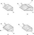
抜け出し防止構造91の断面形状は、抜け出し防止構造91に落石が衝突する場合には傾斜部92に衝突することが望ましいため、図16(a)に示すように矢印の方向から落石が衝突する場合には三角形が望ましい。しかし、例えば図16(b)や図16(c)に示すように、抜け出し防止構造91の断面形状が台形のときでも傾斜部92に矢印の方向から落石が衝突する場合には、断面形状が三角形の抜け出し防止構造91と同様の効果を得ることが可能であり、したがって抜け出し防止構造91の断面形状はこれらに限定されるものではない。また傾斜部92で矢印の方向からの衝撃の耐久力を向上させる為、図16(d)に示すように傾斜部92をアーチ状にしてもかまわない。
When the falling stone collides with the falling
抜け出し防止構造91の構成としては、前記蛇籠71の網籠72と砂,土,自然石,砕石などの土質材料を組み合わせたもの、前記袋体81と前記土質材料あるいはモルタルコンクリートを組み合わせたものなどが望ましいが、前記網籠72や前記袋体81の代わりに高強度プラスチック網(ジオグリッド)を用いたり、合成繊維を使用した軽量で高強度の二重織生地(布製型枠)内に生コンクリートやモルタルを注入することにより一定厚のコンクリート構造物を形成するという工法を用いたり、木材(間伐材)などの材料を用いてもかまわない。
The structure of the slip-out
次に上記構成についてその作用を説明すると、落石が発生し抜け出し防止構造91の傾斜部92に落石が衝突した際、傾斜部92の傾斜は山側である斜面1A側前方が薄く反山側である後方が厚い構成になっているので、落石の進行方向が上方向に誘導される。そして誘導された落石は、落石防護柵の横ロープ材3や金網9で構成された防護面90に捕捉される。
Next, the operation of the above configuration will be described. When a falling rock is generated and a falling rock collides with the
このとき傾斜部92の地面1からの傾斜角度がきつすぎると、落石が傾斜部92に衝突した後にうまく防護面90の中央部に誘導できない可能性が高くなってしまう。また抜け出し防止構造91の高さが高すぎると落石防護柵より上方に落石が誘導される可能性が高くなってしまい、反対に抜け出し防止構造91の高さが低すぎると、落石防護柵の地面1と横ロープ材7との間を落石が通過する可能性が高くなってしまう。しかも落石防護柵の立地条件によってはあまり抜け出し防止構造91の設置場所を確保できない場合もあり、その際抜け出し防止構造91の高さや傾斜部の地面1からの傾斜角度が自由に設定できない場合も想定される。したがって上記作用を得る為、想定される落石の大きさや衝突の際に想定されるエネルギー、落石防護柵の立地条件や種類、防護面90の高さや支柱2A,2Aの間隔、及び抜け出し防止構造91の材料や構成などの条件によって、抜け出し防止構造91の高さや傾斜部92の地面1からの傾斜角度が設定されることが望ましい。例えば想定される落石(球状と仮定する)の重量が3tで地面(落石防護柵の設置面)1からの高さを0〜2m、地面1Aの斜面角度を40度とすると、想定される落石防護柵の高さは4m程、支柱2A,2Aの間隔は3〜10m程になるが、この時の抜け出し防止構造91(断面形状が三角形で前記網籠72と土質材料を組み合わせた構成)の高さは0.5〜1m、地面1からの傾斜角度は約30度が望ましい。
At this time, if the inclination angle of the
なお例えば図16(b)や図16(c)のような断面形状の抜け出し防止構造91では、傾斜部92以外の場所である平坦部93に落石が衝突することも想定される。その際抜け出し防止構造91は、参考例3や4で上述した蛇籠71や袋体81と同様の効果を得ることが可能で、具体的には落石の衝撃を衝突した面である平坦部93で抜け出し防止構造91が吸収すると共に、地面1と横ロープ材7との間を落石が通過することを防止できる。
For example, in the
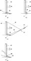
抜け出し防止構造91は設置するだけで固定しなくても、上述した効果のある程度は得ることができる。しかし、抜け出し防止構造91は落石が衝突することが前提になっているので、衝突の際の衝撃で抜け出し防止構造91の位置や傾斜部92の地面1からの傾斜角度がずれてしまう可能性もあり、その場合は上述した効果は確実には得られない。したがって、例えば落石防護柵の支柱2,2Aや地面1などに抜け出し防止構造91を固定することが望ましい。抜け出し防止構造91を固定した場合、固定していない場合と比較してより上記作用を確実に得ることができる。その為抜け出し防止構造91を固定した場合は、固定していない場合と比較して抜け出し防止構造91の小型化が可能になる。抜け出し防止構造91の固定方法の一例として、図17(a)に示すように支柱2,2Aに連結部材94で固定する方法、図17(b)に示すようにアンカー95で地面1に固定する方法、控ワイヤ96がある場合は図17(c)に示すように控ワイヤ用アンカー97から吊り下げ部材98によって抜け出し防止構造91を吊るす方法などが挙げられ、適宜選定可能である。また、抜け出し防止構造91の固定方法はこれらに限定されるものではなく、例えば落石防護柵の防護面90下端が固定されても問題がない場合は、図17(d)に示す様に防護面90下端の横ロープ材7にワイヤ99で固定する方法もある。上記の固定方法(a)〜(d)は複数選択することも可能であり、複数の方法で抜け出し防止構造91を固定した際は、より確実に落石防護柵の地面1と横ロープ材7との間を落石が通過することを防止できる。
Even if the pull-out
このように、本実施例では請求項1に対応して、遮蔽部材が、支柱2,2Aの設置場所の斜面1A側前方(山側)が薄く横ロープ材3側である後方(反山側)が厚い傾斜を有する傾斜部92を設けた抜け出し防止構造91であるから、落石が発生し抜け出し防止構造91の傾斜部92に落石が衝突した際、傾斜部92の傾斜は山側である斜面1A側前方が薄く反山側である後方が厚い構成になっているので、落石の進行方向が上方向に誘導され、抜け出し防止構造91により落石防護柵の地面1と横ロープ材7との間を落石が通過することを防止でき、それに加えて落石が抜け出し防止構造91に衝突した場合、防護面90は落石の衝撃を直接受けないので、支柱2,2A下段における横ロープ材3,7や金網9で構成された防護面90での落石の衝撃を緩和できる。
Thus, in the present embodiment , corresponding to claim 1 , the shielding member is thin on the
また別の本実施例では請求項2に対応して、抜け出し防止構造91が蛇籠71であるから蛇籠71により落石の衝撃を吸収すると共に、設置面と横ロープ材7との間を落石が通過することを防止できる。 In another embodiment, corresponding to claim 2, the
また別の本実施例では請求項7に対応して、抜け出し防止構造91が袋体81であるから袋体81により落石の衝撃を吸収すると共に、設置面と横ロープ材7との間を落石が通過することを防止できる。 In another embodiment, corresponding to claim 7, the slip-out
また、このように本実施例では請求項3に対応して、抜け出し防止構造91を支柱2,2Aに固定しているから、落石の衝突する際の衝撃で抜け出し防止構造91の位置や傾斜部92の地面1からの傾斜角度がずれることがない。そのため、より確実に抜け出し防止構造91により落石防護柵の地面1と横ロープ材7との間を落石が通過することを防止でき、それに加えて横ロープ材3,7や金網9で構成された防護面90での落石の衝撃を緩和できる。
Further, in this embodiment, in accordance with the third aspect of the present invention, since the
また別の本実施例では請求項4に対応して、抜け出し防止構造91を設置面である地面1に固定しているから、落石の衝突する際の衝撃で抜け出し防止構造91の位置や傾斜部92の地面1からの傾斜角度がずれることがない。そのため、より確実に抜け出し防止構造91により落石防護柵の地面1と横ロープ材7との間を落石が通過することを防止でき、それに加えて横ロープ材3,7や金網9で構成された防護面90での落石の衝撃を緩和できる。
In another embodiment, corresponding to claim 4 , the
さらに別の本実施例では請求項5に対応して、支柱2,2Aを支える控えワイヤ96と、控えワイヤ96を固定する控ワイヤ用アンカー97を設けた防護柵において、控ワイヤ用アンカー97より抜け出し防止構造91を吊るしているから、落石の衝突する際の衝撃で抜け出し防止構造81の位置や傾斜部92の地面1からの傾斜角度がずれることがない。そのため、より確実に抜け出し防止構造91により落石防護柵の地面1と横ロープ材7との間を落石が通過することを防止でき、それに加えて横ロープ材3,7や金網9で構成された防護面90での落石の衝撃を緩和できる。
In yet another embodiment, corresponding to claim 5 , a guard fence provided with a
そして別の本実施例では請求項6に対応して、横ロープ材3,7や金網9で構成された防護面90を設けた防護柵において、防護面90に抜け出し防止構造91を固定しているから、落石の衝突する際の衝撃で抜け出し防止構造91の位置や傾斜部92の地面1からの傾斜角度がずれることがない。そのため、より確実に抜け出し防止構造91により落石防護柵の地面1と横ロープ材7との間を落石が通過することを防止でき、それに加えて横ロープ材3,7や金網9で構成された防護面90での落石の衝撃を緩和できる。
In another embodiment, corresponding to claim 6 , in the protective fence provided with the
また、抜け出し防止構造91は構成がシンプルなので安価に製作でき、設置に必要なスペースが少なく、さらに補修や取り替えが容易である。しかも落石防護柵の新設時はもちろん既設の落石防護柵にも抜け出し防止構造91を新たに設置でき、その上防護面90が変形することによって落石の衝撃を吸収する構造の落石防護柵にも対応できるので汎用性が高い。そして落石の衝突する傾斜部92は錆やクリープ,積雪や堆積物などの影響を受け難く、したがって抜け出し防止構造91の性能の経時変化が少ない。
Further, the pull-out
尚、本発明は、本実施例に限定されるものではなく、本発明の要旨の範囲内で種々の変形実施が可能である。例えば、端末支柱に下段の横ロープ材の端部を固定して連結してもよいし、緩衝金具などにより摩擦摺動可能に連結してもよく、下段の横ロープ材と各支柱との係止及び連結構造は適宜選定可能である。さらにコンクリートなどの基礎がある構造の落石防護柵では、落石防護柵の山側の基礎部分を落石防護柵の設置面と下段の横ロープ材間を塞ぐことができる高さに形成し、さらにその山側の基礎部分に山側が薄く反山側が厚い傾斜を有する傾斜部を設けて抜け出し防止構造としてもかまわない。 The present invention is not limited to this embodiment, and various modifications can be made within the scope of the gist of the present invention. For example, the lower the terminal post to the end of the horizontal rope materials may be connected and fixed, may be linked to more friction sliding like a buffer metal, and lower horizontal rope materials and each strut The locking and connecting structure can be selected as appropriate. Furthermore, in rockfall protection fences with a foundation such as concrete, the foundation part on the mountain side of the rockfall protection fence is formed to a height that can block between the installation surface of the rockfall protection fence and the lower horizontal rope material, and the mountain side It is also possible to provide a structure for preventing the slipping out by providing an inclined portion having a slope with a thin mountain side and a thick anti-mountain side at the base portion.
1 地面(設置面)
2 端末支柱
2A 中間支柱
3 横ロープ材
7 横ロープ材
51 網状体(遮蔽部材)
61 線材枠
62 枠材
62T 縦部
62Y 横部
63 横線材
71 蛇籠
81 袋体(遮蔽部材)
91 抜け出し防止構造(遮蔽部材)
1 Ground (installation surface)
2
51 Mesh (shielding member)
61 Wire frame
62 Frame material
62T Vertical
62Y Horizontal
63 Horizontal wire
71 Gabion
81 Bag (shielding member)
91 Pull-out prevention structure (shielding member)
Claims (7)
Priority Applications (1)
| Application Number | Priority Date | Filing Date | Title |
|---|---|---|---|
| JP2011098542A JP5557166B2 (en) | 2010-09-17 | 2011-04-26 | Protective fence |
Applications Claiming Priority (3)
| Application Number | Priority Date | Filing Date | Title |
|---|---|---|---|
| JP2010210064 | 2010-09-17 | ||
| JP2010210064 | 2010-09-17 | ||
| JP2011098542A JP5557166B2 (en) | 2010-09-17 | 2011-04-26 | Protective fence |
Publications (2)
| Publication Number | Publication Date |
|---|---|
| JP2012082677A JP2012082677A (en) | 2012-04-26 |
| JP5557166B2 true JP5557166B2 (en) | 2014-07-23 |
Family
ID=46241828
Family Applications (1)
| Application Number | Title | Priority Date | Filing Date |
|---|---|---|---|
| JP2011098542A Active JP5557166B2 (en) | 2010-09-17 | 2011-04-26 | Protective fence |
Country Status (1)
| Country | Link |
|---|---|
| JP (1) | JP5557166B2 (en) |
Families Citing this family (6)
| Publication number | Priority date | Publication date | Assignee | Title |
|---|---|---|---|---|
| JP6007147B2 (en) * | 2013-05-01 | 2016-10-12 | 株式会社ビーセーフ | Maintenance structure and maintenance method of the lower end of the pillar in the protective fence |
| JP6523075B2 (en) * | 2015-06-30 | 2019-05-29 | 東京製綱株式会社 | Rockfall fence |
| JP6611320B2 (en) * | 2015-10-23 | 2019-11-27 | Jfe建材株式会社 | Flotage capture fence |
| JP6130092B1 (en) * | 2017-03-07 | 2017-05-17 | 株式会社シビル | Shock absorber |
| CN111549804B (en) * | 2020-05-26 | 2021-08-10 | 中国电建集团成都勘测设计研究院有限公司 | Cutting slope reinforced passive protection system and construction method thereof |
| CN112982998B (en) * | 2021-03-10 | 2022-07-12 | 枣庄昊德新型材料科技有限公司 | Sand pile control device for building construction |
Family Cites Families (7)
| Publication number | Priority date | Publication date | Assignee | Title |
|---|---|---|---|---|
| JPS5120003Y2 (en) * | 1971-06-08 | 1976-05-26 | ||
| JPS5453806U (en) * | 1977-09-21 | 1979-04-13 | ||
| JPS6042087Y2 (en) * | 1981-11-18 | 1985-12-23 | 瀬戸内金網商工株式会社 | Rockfall protection fence |
| JP3954414B2 (en) * | 2002-03-11 | 2007-08-08 | 開発コンクリート株式会社 | Protective body using net |
| JP5118930B2 (en) * | 2007-10-01 | 2013-01-16 | Jfe建材株式会社 | Rock fall protection wall |
| JP5311198B2 (en) * | 2007-11-06 | 2013-10-09 | 株式会社天商 | Device for preventing small animals from entering motorways |
| JP4808226B2 (en) * | 2008-02-06 | 2011-11-02 | 株式会社プロテックエンジニアリング | Shock absorbing fence |
-
2011
- 2011-04-26 JP JP2011098542A patent/JP5557166B2/en active Active
Also Published As
| Publication number | Publication date |
|---|---|
| JP2012082677A (en) | 2012-04-26 |
Similar Documents
| Publication | Publication Date | Title |
|---|---|---|
| KR101470685B1 (en) | Shock absorbing fence | |
| KR102081865B1 (en) | Tunnel type rockfall protection structure having variable pole part for shock absorbing | |
| KR101351936B1 (en) | Protection barriers for absorbing impulse | |
| JP5557166B2 (en) | Protective fence | |
| JP6228946B2 (en) | Protective fence | |
| JP5830747B2 (en) | Protective fence | |
| JP2013155493A (en) | Guard fence | |
| JP5953281B2 (en) | Protective fence | |
| JP3143816U (en) | Rock fall protection net structure | |
| JP2907214B1 (en) | Shock absorbing fence | |
| JP5123224B2 (en) | Reinforcement structure of existing rockfall protection fence | |
| JP2016166461A (en) | Impact absorption fence | |
| JP7027124B2 (en) | Protective facilities, energy absorbing surface materials and energy absorbing devices | |
| JP6934768B2 (en) | Guard rail | |
| JP5414555B2 (en) | Protective fence | |
| JP5793633B1 (en) | Protective fence | |
| JP5080373B2 (en) | Transmission type dam | |
| JP2003003425A (en) | Shock absorbing protective fence | |
| JP3639950B2 (en) | Shock absorbing fence | |
| JP5490670B2 (en) | Rock fall protection net structure | |
| JP3844970B2 (en) | Preventive facilities such as falling rocks, earth and sand, driftwood, avalanches and their protection methods | |
| JP4996198B2 (en) | Shock absorbing fence | |
| JP7697132B2 (en) | Rockfall and avalanche prevention fence | |
| JP6990474B1 (en) | Guard rail | |
| KR102908443B1 (en) | Falling stone prevention fence of dual row connection structure with improved buffering performance |
Legal Events
| Date | Code | Title | Description |
|---|---|---|---|
| A621 | Written request for application examination |
Free format text: JAPANESE INTERMEDIATE CODE: A621 Effective date: 20130729 |
|
| A977 | Report on retrieval |
Free format text: JAPANESE INTERMEDIATE CODE: A971007 Effective date: 20140225 |
|
| A131 | Notification of reasons for refusal |
Free format text: JAPANESE INTERMEDIATE CODE: A131 Effective date: 20140304 |
|
| A521 | Request for written amendment filed |
Free format text: JAPANESE INTERMEDIATE CODE: A523 Effective date: 20140422 |
|
| TRDD | Decision of grant or rejection written | ||
| A01 | Written decision to grant a patent or to grant a registration (utility model) |
Free format text: JAPANESE INTERMEDIATE CODE: A01 Effective date: 20140512 |
|
| R150 | Certificate of patent or registration of utility model |
Ref document number: 5557166 Country of ref document: JP Free format text: JAPANESE INTERMEDIATE CODE: R150 |
|
| A61 | First payment of annual fees (during grant procedure) |
Free format text: JAPANESE INTERMEDIATE CODE: A61 Effective date: 20140525 |
|
| R250 | Receipt of annual fees |
Free format text: JAPANESE INTERMEDIATE CODE: R250 |
|
| R250 | Receipt of annual fees |
Free format text: JAPANESE INTERMEDIATE CODE: R250 |
|
| R250 | Receipt of annual fees |
Free format text: JAPANESE INTERMEDIATE CODE: R250 |
|
| R250 | Receipt of annual fees |
Free format text: JAPANESE INTERMEDIATE CODE: R250 |
|
| R250 | Receipt of annual fees |
Free format text: JAPANESE INTERMEDIATE CODE: R250 |
|
| R250 | Receipt of annual fees |
Free format text: JAPANESE INTERMEDIATE CODE: R250 |
|
| R250 | Receipt of annual fees |
Free format text: JAPANESE INTERMEDIATE CODE: R250 |
|
| R250 | Receipt of annual fees |
Free format text: JAPANESE INTERMEDIATE CODE: R250 |
|
| R250 | Receipt of annual fees |
Free format text: JAPANESE INTERMEDIATE CODE: R250 |