JP5556291B2 - Developer cartridge - Google Patents

Developer cartridge Download PDF

Info

Publication number
JP5556291B2
JP5556291B2 JP2010068573A JP2010068573A JP5556291B2 JP 5556291 B2 JP5556291 B2 JP 5556291B2 JP 2010068573 A JP2010068573 A JP 2010068573A JP 2010068573 A JP2010068573 A JP 2010068573A JP 5556291 B2 JP5556291 B2 JP 5556291B2
Authority
JP
Japan
Prior art keywords
detected
gear
developing cartridge
rotating body
axis
Prior art date
Legal status (The legal status is an assumption and is not a legal conclusion. Google has not performed a legal analysis and makes no representation as to the accuracy of the status listed.)
Active
Application number
JP2010068573A
Other languages
Japanese (ja)
Other versions
JP2011203363A (en
Inventor
猛行 高木
Current Assignee (The listed assignees may be inaccurate. Google has not performed a legal analysis and makes no representation or warranty as to the accuracy of the list.)
Brother Industries Ltd
Original Assignee
Brother Industries Ltd
Priority date (The priority date is an assumption and is not a legal conclusion. Google has not performed a legal analysis and makes no representation as to the accuracy of the date listed.)
Filing date
Publication date
Application filed by Brother Industries Ltd filed Critical Brother Industries Ltd
Priority to JP2010068573A priority Critical patent/JP5556291B2/en
Priority to ES11002316.5T priority patent/ES2544460T3/en
Priority to DE202011110659.8U priority patent/DE202011110659U1/en
Priority to DE202011110668.7U priority patent/DE202011110668U1/en
Priority to US13/053,074 priority patent/US8676064B2/en
Priority to PL11002316T priority patent/PL2369421T3/en
Priority to EP11002316.5A priority patent/EP2369421B1/en
Priority to EP15160556.5A priority patent/EP2905660B1/en
Priority to CN201110077194.1A priority patent/CN102200726B/en
Priority to CN201410562527.3A priority patent/CN104360586B/en
Priority to PCT/JP2011/057128 priority patent/WO2011118690A1/en
Publication of JP2011203363A publication Critical patent/JP2011203363A/en
Priority to US14/189,305 priority patent/US9104172B2/en
Application granted granted Critical
Publication of JP5556291B2 publication Critical patent/JP5556291B2/en
Priority to US14/790,388 priority patent/US9405266B2/en
Priority to US15/186,970 priority patent/US9709926B2/en
Active legal-status Critical Current
Anticipated expiration legal-status Critical

Links

Images

Classifications

    • GPHYSICS
    • G03PHOTOGRAPHY; CINEMATOGRAPHY; ANALOGOUS TECHNIQUES USING WAVES OTHER THAN OPTICAL WAVES; ELECTROGRAPHY; HOLOGRAPHY
    • G03GELECTROGRAPHY; ELECTROPHOTOGRAPHY; MAGNETOGRAPHY
    • G03G15/00Apparatus for electrographic processes using a charge pattern
    • G03G15/06Apparatus for electrographic processes using a charge pattern for developing
    • G03G15/08Apparatus for electrographic processes using a charge pattern for developing using a solid developer, e.g. powder developer
    • G03G15/0822Arrangements for preparing, mixing, supplying or dispensing developer
    • G03G15/0887Arrangements for conveying and conditioning developer in the developing unit, e.g. agitating, removing impurities or humidity
    • G03G15/0889Arrangements for conveying and conditioning developer in the developing unit, e.g. agitating, removing impurities or humidity for agitation or stirring
    • GPHYSICS
    • G03PHOTOGRAPHY; CINEMATOGRAPHY; ANALOGOUS TECHNIQUES USING WAVES OTHER THAN OPTICAL WAVES; ELECTROGRAPHY; HOLOGRAPHY
    • G03GELECTROGRAPHY; ELECTROPHOTOGRAPHY; MAGNETOGRAPHY
    • G03G21/00Arrangements not provided for by groups G03G13/00 - G03G19/00, e.g. cleaning, elimination of residual charge
    • G03G21/16Mechanical means for facilitating the maintenance of the apparatus, e.g. modular arrangements
    • G03G21/1604Arrangement or disposition of the entire apparatus
    • G03G21/1623Means to access the interior of the apparatus
    • GPHYSICS
    • G03PHOTOGRAPHY; CINEMATOGRAPHY; ANALOGOUS TECHNIQUES USING WAVES OTHER THAN OPTICAL WAVES; ELECTROGRAPHY; HOLOGRAPHY
    • G03GELECTROGRAPHY; ELECTROPHOTOGRAPHY; MAGNETOGRAPHY
    • G03G15/00Apparatus for electrographic processes using a charge pattern
    • G03G15/06Apparatus for electrographic processes using a charge pattern for developing
    • G03G15/08Apparatus for electrographic processes using a charge pattern for developing using a solid developer, e.g. powder developer
    • G03G15/0822Arrangements for preparing, mixing, supplying or dispensing developer
    • G03G15/0865Arrangements for supplying new developer
    • GPHYSICS
    • G03PHOTOGRAPHY; CINEMATOGRAPHY; ANALOGOUS TECHNIQUES USING WAVES OTHER THAN OPTICAL WAVES; ELECTROGRAPHY; HOLOGRAPHY
    • G03GELECTROGRAPHY; ELECTROPHOTOGRAPHY; MAGNETOGRAPHY
    • G03G15/00Apparatus for electrographic processes using a charge pattern
    • G03G15/06Apparatus for electrographic processes using a charge pattern for developing
    • G03G15/08Apparatus for electrographic processes using a charge pattern for developing using a solid developer, e.g. powder developer
    • G03G15/0896Arrangements or disposition of the complete developer unit or parts thereof not provided for by groups G03G15/08 - G03G15/0894
    • GPHYSICS
    • G03PHOTOGRAPHY; CINEMATOGRAPHY; ANALOGOUS TECHNIQUES USING WAVES OTHER THAN OPTICAL WAVES; ELECTROGRAPHY; HOLOGRAPHY
    • G03GELECTROGRAPHY; ELECTROPHOTOGRAPHY; MAGNETOGRAPHY
    • G03G21/00Arrangements not provided for by groups G03G13/00 - G03G19/00, e.g. cleaning, elimination of residual charge
    • G03G21/16Mechanical means for facilitating the maintenance of the apparatus, e.g. modular arrangements
    • G03G21/1642Mechanical means for facilitating the maintenance of the apparatus, e.g. modular arrangements for connecting the different parts of the apparatus
    • G03G21/1647Mechanical connection means
    • GPHYSICS
    • G03PHOTOGRAPHY; CINEMATOGRAPHY; ANALOGOUS TECHNIQUES USING WAVES OTHER THAN OPTICAL WAVES; ELECTROGRAPHY; HOLOGRAPHY
    • G03GELECTROGRAPHY; ELECTROPHOTOGRAPHY; MAGNETOGRAPHY
    • G03G21/00Arrangements not provided for by groups G03G13/00 - G03G19/00, e.g. cleaning, elimination of residual charge
    • G03G21/16Mechanical means for facilitating the maintenance of the apparatus, e.g. modular arrangements
    • G03G21/18Mechanical means for facilitating the maintenance of the apparatus, e.g. modular arrangements using a processing cartridge, whereby the process cartridge comprises at least two image processing means in a single unit
    • G03G21/1875Mechanical means for facilitating the maintenance of the apparatus, e.g. modular arrangements using a processing cartridge, whereby the process cartridge comprises at least two image processing means in a single unit provided with identifying means or means for storing process- or use parameters, e.g. lifetime of the cartridge
    • G03G21/1896Mechanical means for facilitating the maintenance of the apparatus, e.g. modular arrangements using a processing cartridge, whereby the process cartridge comprises at least two image processing means in a single unit provided with identifying means or means for storing process- or use parameters, e.g. lifetime of the cartridge mechanical or optical identification means, e.g. protrusions, bar codes
    • GPHYSICS
    • G03PHOTOGRAPHY; CINEMATOGRAPHY; ANALOGOUS TECHNIQUES USING WAVES OTHER THAN OPTICAL WAVES; ELECTROGRAPHY; HOLOGRAPHY
    • G03GELECTROGRAPHY; ELECTROPHOTOGRAPHY; MAGNETOGRAPHY
    • G03G2221/00Processes not provided for by group G03G2215/00, e.g. cleaning or residual charge elimination
    • G03G2221/16Mechanical means for facilitating the maintenance of the apparatus, e.g. modular arrangements and complete machine concepts
    • G03G2221/163Mechanical means for facilitating the maintenance of the apparatus, e.g. modular arrangements and complete machine concepts for the developer unit
    • GPHYSICS
    • G03PHOTOGRAPHY; CINEMATOGRAPHY; ANALOGOUS TECHNIQUES USING WAVES OTHER THAN OPTICAL WAVES; ELECTROGRAPHY; HOLOGRAPHY
    • G03GELECTROGRAPHY; ELECTROPHOTOGRAPHY; MAGNETOGRAPHY
    • G03G2221/00Processes not provided for by group G03G2215/00, e.g. cleaning or residual charge elimination
    • G03G2221/16Mechanical means for facilitating the maintenance of the apparatus, e.g. modular arrangements and complete machine concepts
    • G03G2221/1651Mechanical means for facilitating the maintenance of the apparatus, e.g. modular arrangements and complete machine concepts for connecting the different parts
    • G03G2221/1654Locks and means for positioning or alignment
    • GPHYSICS
    • G03PHOTOGRAPHY; CINEMATOGRAPHY; ANALOGOUS TECHNIQUES USING WAVES OTHER THAN OPTICAL WAVES; ELECTROGRAPHY; HOLOGRAPHY
    • G03GELECTROGRAPHY; ELECTROPHOTOGRAPHY; MAGNETOGRAPHY
    • G03G2221/00Processes not provided for by group G03G2215/00, e.g. cleaning or residual charge elimination
    • G03G2221/16Mechanical means for facilitating the maintenance of the apparatus, e.g. modular arrangements and complete machine concepts
    • G03G2221/18Cartridge systems
    • G03G2221/183Process cartridge
    • G03G2221/1892Presence detection

Description

本発明は、レーザプリンタなどの画像形成装置の装置本体内に着脱可能に装着される現像カートリッジに関する。   The present invention relates to a developing cartridge that is detachably mounted in an apparatus main body of an image forming apparatus such as a laser printer.

レーザプリンタなどの画像形成装置には、たとえば、装置本体内に現像カートリッジが着脱可能に装着されるタイプのものがある。現像カートリッジ内には、トナーが収容されている。現像カートリッジ内のトナーがなくなると、その現像カートリッジは、装置本体内から取り出される。そして、新品の現像カートリッジが装置本体内に装着される。また、装置本体内で用紙のジャムが発生したときに、装置本体内から現像カートリッジが取り出され、ジャムの解消後、その現像カートリッジが装置本体内に再び装着されることがある。   An image forming apparatus such as a laser printer includes a type in which a developing cartridge is detachably mounted in the apparatus main body. The developing cartridge contains toner. When the toner in the developing cartridge runs out, the developing cartridge is taken out from the apparatus main body. Then, a new developing cartridge is mounted in the apparatus main body. Further, when a paper jam occurs in the apparatus main body, the developing cartridge may be taken out from the apparatus main body, and after the jam is resolved, the developing cartridge may be mounted in the apparatus main body again.

このタイプの画像形成装置において、当接突起を備える検出ギヤが現像カートリッジの側面に配置され、装置本体内に現像カートリッジが装着されたときに、検出ギヤの回転に基づいて、その現像カートリッジに関する情報を取得するものが提案されている。   In this type of image forming apparatus, when a detection gear having a contact protrusion is disposed on a side surface of the developing cartridge and the developing cartridge is mounted in the apparatus main body, information on the developing cartridge is based on the rotation of the detecting gear. Something to get is proposed.

検出ギヤは、現像カートリッジの側面と直交する方向に延びる軸線を中心に回転可能に設けられている。検出ギヤの周面には、その一部を除いて、ギヤ歯が形成されている。すなわち、検出ギヤは、欠け歯ギヤである。また、現像カートリッジの側面には、伝達ギヤが検出ギヤの軸線と間隔を空けて平行に延びる軸線を中心に回転可能に設けられている。伝達ギヤの周面には、その全周にわたって、ギヤ歯が形成されている。現像カートリッジが新品の状態では、検出ギヤのギヤ歯に伝達ギヤのギヤ歯が噛合している。新品の現像カートリッジが装置本体内に装着されて、伝達ギヤにモータの駆動力が入力されると、その駆動力が伝達ギヤから検出ギヤにそれらのギヤ歯を介して伝達される。   The detection gear is provided to be rotatable around an axis extending in a direction orthogonal to the side surface of the developing cartridge. Gear teeth are formed on the peripheral surface of the detection gear except for a part thereof. That is, the detection gear is a chipped gear. In addition, a transmission gear is provided on the side surface of the developing cartridge so as to be rotatable about an axis extending parallel to the axis of the detection gear. Gear teeth are formed on the circumferential surface of the transmission gear over the entire circumference. When the developing cartridge is new, the gear teeth of the transmission gear are engaged with the gear teeth of the detection gear. When a new developing cartridge is mounted in the apparatus main body and the driving force of the motor is input to the transmission gear, the driving force is transmitted from the transmission gear to the detection gear via the gear teeth.

これにより、検出ギヤが回転し、この検出ギヤの回転に伴って、当接突起が移動する。装置本体内には、当接突起の通過を検出するセンサが設けられている。そして、モータの駆動開始から一定時間内に、センサにより当接突起の通過が検出されたか否かに基づいて、現像カートリッジが新品であるか旧品であるかが判別される。検出ギヤの回転が進み、検出ギヤの欠け歯部分が伝達ギヤのギヤ歯と対向すると、伝達ギヤのギヤ歯と検出ギヤのギヤ歯との噛合が解除され、検出ギヤの回転が停止する。   As a result, the detection gear rotates, and the contact protrusion moves as the detection gear rotates. A sensor for detecting the passage of the contact protrusion is provided in the apparatus main body. Then, it is determined whether the developing cartridge is a new product or an old product based on whether or not the passage of the contact protrusion is detected by the sensor within a certain time from the start of driving of the motor. When the rotation of the detection gear advances and the missing tooth portion of the detection gear faces the gear teeth of the transmission gear, the meshing between the gear teeth of the transmission gear and the gear teeth of the detection gear is released, and the rotation of the detection gear stops.

特開2006−267994号公報JP 2006-267994 A

本発明の目的は、検知ギヤなどの被検知回転体を備えながら、従来よりも便利な現像カートリッジを提供することである。   SUMMARY OF THE INVENTION An object of the present invention is to provide a developing cartridge that is more convenient than conventional ones while including a detected rotating body such as a detection gear.

前記の目的を達成するため、本発明は、画像形成装置の装置本体内に着脱可能に装着される現像カートリッジであって、互いに対向して配置される第1側壁および第2側壁を有し、内部に現像剤を収容する筺体と、前記第1側壁の外側に、前記第1側壁および前記第2側壁の対向方向に延びる第1軸線を中心に回転可能に設けられ、前記装置本体内に備えられた駆動出力部材が接続されて、前記駆動出力部材から駆動力を受ける受動部材と、前記第1側壁と前記第2側壁との間に、前記第1軸線と間隔を空けて平行に延びる第2軸線を中心に回転可能に設けられ、前記受動部材が受ける駆動力により回転する現像ローラと、前記第1側壁の外側に、前記第1軸線と間隔を空けて平行に延びる第3軸線を中心に回転可能に設けられ、前記装置本体内に備えられた検知部材の検知対象である被検知部、および前記被検知部に対して前記第3軸線を中心とする回転方向に間隔を空けて配置される接触部を有し、当該現像カートリッジが前記装置本体内に装着される過程において、前記接触部が前記装置本体内に固定的に配置された干渉部材に接触することにより、退避位置から前記受動部材が受ける駆動力により回転可能となる初期位置まで回転する被検知回転体とを備えることを特徴としている。   In order to achieve the above-described object, the present invention provides a developing cartridge that is detachably mounted in a main body of an image forming apparatus, and includes a first side wall and a second side wall that are arranged to face each other. Provided inside the apparatus main body is a housing that accommodates a developer therein, and is provided outside the first side wall so as to be rotatable about a first axis that extends in the opposing direction of the first side wall and the second side wall. And a second member extending between the first side wall and the second side wall in parallel with a space between the first side wall and the second side wall. A developing roller that is rotatable about two axes and rotates by a driving force received by the passive member, and a third axis that extends outside the first side wall and extends in parallel with the first axis at a distance. The device book is rotatably provided A development portion having a detection portion that is a detection target of a detection member provided in the inside, and a contact portion that is disposed with a space in the rotation direction about the third axis with respect to the detection portion; In the process of mounting the cartridge in the apparatus main body, the contact portion comes into contact with an interference member fixedly arranged in the apparatus main body, so that it can be rotated by the driving force received by the passive member from the retracted position. And a detected rotating body that rotates to an initial position.

本発明によれば、筺体の第1側壁の外側には、受動部材および被検知回転体がそれぞれ第1軸線および第3軸線を中心に回転可能に設けられている。また、第1側壁と第2側壁との間には、現像ローラが第1軸線と平行に延びる第2軸線を中心に回転可能に設けられている。   According to the present invention, the passive member and the detected rotating body are rotatably provided around the first axis and the third axis on the outside of the first side wall of the housing. A developing roller is provided between the first side wall and the second side wall so as to be rotatable about a second axis extending parallel to the first axis.

受動部材には、装置本体内に備えられた駆動出力部材が接続されて、駆動出力部材から駆動力が入力される。この受動部材に入力される駆動力(受動部材が駆動出力部材から受ける駆動力)により、現像ローラが回転する。   A driving output member provided in the apparatus main body is connected to the passive member, and driving force is input from the driving output member. The developing roller is rotated by the driving force input to the passive member (the driving force received by the passive member from the drive output member).

被検知回転体は、被検知部および接触部を有している。接触部は、現像カートリッジが前記装置本体内に装着される過程において、装置本体内に固定的に配置された干渉部材に接触する。これにより、被検知回転体は、退避位置から初期位置まで回転し、受動部材が受ける駆動力により回転可能となる。   The detected rotating body has a detected portion and a contact portion. The contact portion contacts an interference member fixedly disposed in the apparatus main body in the process of mounting the developing cartridge in the apparatus main body. Thereby, the detected rotating body rotates from the retracted position to the initial position, and can be rotated by the driving force received by the passive member.

そして、現像カートリッジが装置本体内に装着される前においては、被検知回転体の回転位置が退避位置であり、被検知回転体は、受動部材から駆動が切り離され、受動部材が受ける駆動力により回転しない。   Before the developing cartridge is mounted in the apparatus main body, the rotational position of the detected rotating body is the retracted position, and the detected rotating body is separated from the passive member by the driving force received by the passive member. Does not rotate.

たとえば、現像カートリッジの製造ラインにおいて、現像カートリッジの組立後に、現像カートリッジの動作確認が行われることがある。この動作確認のために受動部材に駆動力が入力され、これにより被検知回転体が回転し、被検知部が移動すると、新品の現像カートリッジであっても、装置本体内に装着されたときに、検知部材による被検知部の検知結果に基づいて、現像カートリッジが旧品であると判定されてしまうおそれがある。   For example, in the developing cartridge manufacturing line, the operation of the developing cartridge may be checked after the developing cartridge is assembled. To confirm the operation, a driving force is input to the passive member. As a result, the detected rotating body rotates and the detected part moves. Based on the detection result of the detected part by the detection member, the developing cartridge may be determined to be an old product.

被検知回転体の回転位置が退避位置であるときには、受動部材に駆動力が入力されても、被検知回転体が回転しないので、現像カートリッジの組立後に、被検知回転体を回転させることなく、現像カートリッジの動作確認を行うことができる。したがって、現像カートリッジの動作確認が行われても、現像カートリッジが装置本体内に装着された後に、検知部材による被検知部の検知結果に基づいて、現像カートリッジが新品であるか旧品であるかなど、現像カートリッジに関する情報を良好に取得することができる。   When the rotational position of the detected rotating body is the retracted position, even if a driving force is input to the passive member, the detected rotating body does not rotate. The operation of the developing cartridge can be confirmed. Therefore, even if the operation of the developing cartridge is checked, whether the developing cartridge is new or old based on the detection result of the detected part by the detecting member after the developing cartridge is mounted in the apparatus main body. For example, information regarding the developing cartridge can be acquired favorably.

よって、本発明に係る現像カートリッジは、被検知回転体を備えながら、従来の現像カートリッジよりも便利である。   Therefore, the developing cartridge according to the present invention is more convenient than the conventional developing cartridge while including the detected rotating body.

また、被検知部と接触部とが分けて形成されているので、これらが同一部として形成された構成と比較して、被検知部の摩耗ならびに被検知部および接触部の各位置精度の点で優れている。すなわち、被検知部が接触部を兼ねていると、被検知部が装置本体内の干渉部材との接触により摩耗するおそれがある。また、被検知部および接触部の各部の機能が良好に満たされるように、それらの配置を個別に決定して、被検知部および接触部をその決定した各位置に精度よく配置することができる。   In addition, since the detected part and the contact part are formed separately, the wear of the detected part and the positional accuracy of the detected part and the contact part are compared with the structure in which these parts are formed as the same part. Is excellent. That is, if the detected portion also serves as the contact portion, the detected portion may be worn due to contact with the interference member in the apparatus main body. In addition, the arrangement of the parts to be detected and the contact part can be determined separately so that the functions of the parts of the part to be detected and the contact part can be satisfactorily satisfied, and the part to be detected and the contact part can be accurately arranged at the determined positions. .

図1は、本発明の一実施形態に係る現像カートリッジが装着されたレーザプリンタの断面図である。FIG. 1 is a sectional view of a laser printer equipped with a developing cartridge according to an embodiment of the present invention. 図2Aは、現像カートリッジの左後方から見た斜視図である。FIG. 2A is a perspective view of the developing cartridge as viewed from the left rear. 図2Bは、図2Aに示す現像カートリッジの左側面図であり、ギヤカバーが取り付けられた状態を示す。2B is a left side view of the developing cartridge shown in FIG. 2A and shows a state where a gear cover is attached. 図2Cは、図2Aに示す現像カートリッジの左側面図である。2C is a left side view of the developing cartridge shown in FIG. 2A. 図2Dは、図2Aに示す現像カートリッジの左側面図であり、被検知回転体の一部を欠落させた状態を示す。FIG. 2D is a left side view of the developing cartridge shown in FIG. 2A and shows a state where a part of the detected rotating body is missing. 図2Eは、図2Aに示す現像カートリッジの一部の斜視図であり、その一部を拡大して示す。FIG. 2E is a perspective view of a part of the developing cartridge shown in FIG. 2A, and shows a part thereof in an enlarged manner. 図3Aは、現像カートリッジの左後方から見た斜視図であり、本体ケーシング内に装着された直後の状態を示す。FIG. 3A is a perspective view of the developing cartridge as viewed from the left rear, and shows a state immediately after being mounted in the main body casing. 図3Bは、図3Aに示す現像カートリッジの左側面図であり、ギヤカバーが取り付けられた状態を示す。FIG. 3B is a left side view of the developing cartridge shown in FIG. 3A and shows a state where a gear cover is attached. 図3Cは、図3Aに示す現像カートリッジの左側面図である。3C is a left side view of the developing cartridge shown in FIG. 3A. 図3Dは、図3Aに示す現像カートリッジの左側面図であり、被検知回転体の一部を欠落させた状態を示す。FIG. 3D is a left side view of the developing cartridge shown in FIG. 3A and shows a state where a part of the detected rotating body is missing. 図4Aは、現像カートリッジの左後方から見た斜視図であり、図3Aに示す状態の次の状態を示す。4A is a perspective view of the developing cartridge as viewed from the left rear side, and shows a state next to the state shown in FIG. 3A. 図4Bは、図4Aに示す現像カートリッジの左側面図であり、ギヤカバーが取り付けられた状態を示す。FIG. 4B is a left side view of the developing cartridge shown in FIG. 4A and shows a state where a gear cover is attached. 図4Cは、図4Aに示す現像カートリッジの左側面図である。4C is a left side view of the developing cartridge shown in FIG. 4A. 図4Dは、図4Aに示す現像カートリッジの左側面図であり、被検知回転体の一部を欠落させた状態を示す。FIG. 4D is a left side view of the developing cartridge shown in FIG. 4A and shows a state in which a part of the detected rotating body is missing. 図5Aは、現像カートリッジの左後方から見た斜視図であり、図4Aに示す状態の次の状態を示す。FIG. 5A is a perspective view of the developing cartridge as viewed from the left rear side, and shows a state next to the state shown in FIG. 4A. 図5Bは、図5Aに示す現像カートリッジの左側面図であり、ギヤカバーが取り付けられた状態を示す。FIG. 5B is a left side view of the developing cartridge shown in FIG. 5A and shows a state where a gear cover is attached. 図5Cは、図5Aに示す現像カートリッジの左側面図である。FIG. 5C is a left side view of the developing cartridge shown in FIG. 5A. 図5Dは、図5Aに示す現像カートリッジの左側面図であり、被検知回転体の一部を欠落させた状態を示す。FIG. 5D is a left side view of the developing cartridge shown in FIG. 5A and shows a state in which a part of the detected rotating body is missing. 図6Aは、現像カートリッジの左後方から見た斜視図であり、図5Aに示す状態の次の状態を示す。6A is a perspective view of the developing cartridge as viewed from the left rear side, and shows a state next to the state shown in FIG. 5A. 図6Bは、図6Aに示す現像カートリッジの左側面図であり、ギヤカバーが取り付けられた状態を示す。FIG. 6B is a left side view of the developing cartridge shown in FIG. 6A and shows a state where a gear cover is attached. 図6Cは、図6Aに示す現像カートリッジの左側面図である。6C is a left side view of the developing cartridge shown in FIG. 6A. 図6Dは、図67Aに示す現像カートリッジの左側面図であり、被検知回転体の一部を欠落させた状態を示す。FIG. 6D is a left side view of the developing cartridge shown in FIG. 67A and shows a state in which a part of the detected rotating body is missing. 図7Aは、現像カートリッジの左後方から見た斜視図であり、図6Aに示す状態の次の状態を示す。FIG. 7A is a perspective view of the developing cartridge as seen from the left rear side, and shows a state next to the state shown in FIG. 6A. 図7Bは、図7Aに示す現像カートリッジの左側面図であり、ギヤカバーが取り付けられた状態を示す。FIG. 7B is a left side view of the developing cartridge shown in FIG. 7A and shows a state where a gear cover is attached. 図7Cは、図7Aに示す現像カートリッジの左側面図である。FIG. 7C is a left side view of the developing cartridge shown in FIG. 7A. 図7Dは、図7Aに示す現像カートリッジの左側面図であり、被検知回転体の一部を欠落させた状態を示す。FIG. 7D is a left side view of the developing cartridge shown in FIG. 7A and shows a state in which a part of the detected rotating body is missing. 図7Eは、図7Aに示す現像カートリッジの一部の斜視図であり、その一部を拡大して示す。FIG. 7E is a perspective view of a part of the developing cartridge shown in FIG. 7A, and shows an enlarged part thereof. 図8Aは、現像カートリッジの左後方から見た斜視図であり、図7Aに示す状態の次の状態を示す。FIG. 8A is a perspective view of the developing cartridge as viewed from the left rear side, and shows a state next to the state shown in FIG. 7A. 図8Bは、図8Aに示す現像カートリッジの左側面図であり、ギヤカバーが取り付けられた状態を示す。FIG. 8B is a left side view of the developing cartridge shown in FIG. 8A and shows a state where a gear cover is attached. 図8Cは、図8Aに示す現像カートリッジの左側面図である。FIG. 8C is a left side view of the developing cartridge shown in FIG. 8A. 図8Dは、図8Aに示す現像カートリッジの左側面図であり、被検知回転体の一部を欠落させた状態を示す。FIG. 8D is a left side view of the developing cartridge shown in FIG. 8A and shows a state in which a part of the detected rotating body is missing. 図9Aは、現像カートリッジの左後方から見た斜視図であり、図8Aに示す状態の次の状態を示す。FIG. 9A is a perspective view of the developing cartridge as viewed from the left rear side, and shows a state next to the state shown in FIG. 8A. 図9Bは、図9Aに示す現像カートリッジの左側面図であり、ギヤカバーが取り付けられた状態を示す。FIG. 9B is a left side view of the developing cartridge shown in FIG. 9A and shows a state where a gear cover is attached. 図9Cは、図9Aに示す現像カートリッジの左側面図である。FIG. 9C is a left side view of the developing cartridge shown in FIG. 9A. 図9Dは、図9Aに示す現像カートリッジの左側面図であり、被検知回転体の一部を欠落させた状態を示す。FIG. 9D is a left side view of the developing cartridge shown in FIG. 9A and shows a state in which a part of the detected rotating body is missing. 図10Aは、現像カートリッジの左後方から見た斜視図であり、図9Aに示す状態の次の状態を示す。FIG. 10A is a perspective view of the developing cartridge as viewed from the left rear side, and shows a state next to the state shown in FIG. 9A. 図10Bは、図10Aに示す現像カートリッジの左側面図であり、ギヤカバーが取り付けられた状態を示す。FIG. 10B is a left side view of the developing cartridge shown in FIG. 10A and shows a state where a gear cover is attached. 図10Cは、図10Aに示す現像カートリッジの左側面図である。FIG. 10C is a left side view of the developing cartridge shown in FIG. 10A. 図10Dは、図10Aに示す現像カートリッジの左側面図であり、被検知回転体の一部を欠落させた状態を示す。FIG. 10D is a left side view of the developing cartridge shown in FIG. 10A and shows a state in which a part of the detected rotating body is missing. 図11Aは、現像カートリッジの左後方から見た斜視図であり、図10Aに示す状態の次の状態を示す。FIG. 11A is a perspective view of the developing cartridge as viewed from the left rear side, and shows a state next to the state shown in FIG. 10A. 図11Bは、図11Aに示す現像カートリッジの左側面図であり、ギヤカバーが取り付けられた状態を示す。FIG. 11B is a left side view of the developing cartridge shown in FIG. 11A and shows a state where a gear cover is attached. 図11Cは、図11Aに示す現像カートリッジの左側面図である。FIG. 11C is a left side view of the developing cartridge shown in FIG. 11A. 図11Dは、図11Aに示す現像カートリッジの左側面図であり、被検知回転体の一部を欠落させた状態を示す。FIG. 11D is a left side view of the developing cartridge shown in FIG. 11A and shows a state where a part of the detected rotating body is missing. 図12は、現像カートリッジの装着検出および新品検出時の主要部の動作タイミングを示すタイミングチャートである。FIG. 12 is a timing chart showing the operation timing of the main part at the time of detecting the mounting of the developing cartridge and detecting the new article. 図13は、現像カートリッジの装着検出および新品検出時の主要部の他の動作タイミング(第3検知部が省略された構成でのタイミング)を示すタイミングチャートである。FIG. 13 is a timing chart showing other operation timings of main parts (timing in a configuration in which the third detection unit is omitted) at the time of detecting the mounting of the developing cartridge and detecting the new article. 図14は、係合部がアジテータギヤと別体に形成された構成(変形例1)を示す平面図である。FIG. 14 is a plan view showing a configuration (Modification 1) in which the engaging portion is formed separately from the agitator gear. 図15は、係合部がアジテータギヤと別のギヤと一体的に形成された構成(変形例2)を示す図解的な側面図である。FIG. 15 is an illustrative side view showing a configuration (Modification 2) in which the engaging portion is formed integrally with an agitator gear and another gear. 図16は、第1被検知部と第2被検知部とが一体化された構成(変形例3)を示す側面図である。FIG. 16 is a side view showing a configuration (Modification 3) in which the first detected portion and the second detected portion are integrated. 図17は、被検知回転体の欠け歯ギヤ部に代わる構成(変形例4)を示す図解的な側面図である。FIG. 17 is a schematic side view showing a configuration (Modification 4) instead of the chipped gear portion of the detected rotating body. 図18は、現像カートリッジの装着検出および新品検出のためのフローチャートの一例(モータ駆動前に現像カートリッジの装着の有無が判別される例)である。FIG. 18 is an example of a flowchart for detecting the mounting of a developing cartridge and detecting a new product (an example of determining whether a developing cartridge is mounted before driving a motor). 図19は、現像カートリッジの装着検出および新品検出のためのフローチャートの他の例(モータ駆動後に現像カートリッジの装着の有無が判別される例)である。FIG. 19 is another example of the flowchart for detecting the mounting of the developing cartridge and detecting the new article (an example in which the presence or absence of the mounting of the developing cartridge is determined after the motor is driven).

以下では、本発明の実施の形態について、添付図面を参照しつつ詳細に説明する。
1.レーザプリンタの全体構成
図1に示されるように、画像形成装置の一例としてのレーザプリンタ1は、装置本体の一例としての本体ケーシング2を備えている。本体ケーシング2の一方側壁には、カートリッジ着脱口3が形成され、このカートリッジ着脱口3を開閉するフロントカバー4が設けられている。
Hereinafter, embodiments of the present invention will be described in detail with reference to the accompanying drawings.
1. As shown in FIG. 1, a laser printer 1 as an example of an image forming apparatus includes a main body casing 2 as an example of an apparatus main body. A cartridge attaching / detaching port 3 is formed on one side wall of the main body casing 2, and a front cover 4 for opening and closing the cartridge attaching / detaching port 3 is provided.

なお、以下の説明において、フロントカバー4が設けられている側をレーザプリンタ1の前側とする。レーザプリンタ1の上下左右に関しては、レーザプリンタ1を前側から見たときを基準とする。また、後述する現像カートリッジ7の前後については、本体ケーシング2に装着された状態を基準とし、その上下左右については、現像カートリッジ7を前側から見たときを基準とする。   In the following description, the side on which the front cover 4 is provided is the front side of the laser printer 1. With respect to the top, bottom, left and right of the laser printer 1, the laser printer 1 is taken as a reference when viewed from the front side. Further, the front and rear of the developing cartridge 7 to be described later are based on the state where the developing cartridge 7 is mounted, and the upper, lower, left and right thereof are based on the time when the developing cartridge 7 is viewed from the front side.

本体ケーシング2内の中央より少し前側の位置には、プロセスカートリッジ5が装着されている。プロセスカートリッジ5は、フロントカバー4を開いた状態で、カートリッジ着脱口3を介して、本体ケーシング2内に装着され、また、本体ケーシング2内から離脱される。   A process cartridge 5 is mounted at a position slightly ahead of the center in the main casing 2. The process cartridge 5 is mounted in the main body casing 2 via the cartridge attaching / detaching port 3 with the front cover 4 opened, and is detached from the main body casing 2.

プロセスカートリッジ5は、ドラムカートリッジ6と、そのドラムカートリッジ6に着脱自在に装着される現像カートリッジ7とからなる。   The process cartridge 5 includes a drum cartridge 6 and a developing cartridge 7 that is detachably attached to the drum cartridge 6.

ドラムカートリッジ6は、ドラムフレーム8を備えている。ドラムフレーム8の後端部には、感光ドラム9が回転可能に保持されている。また、ドラムフレーム8には、帯電器10および転写ローラ11が保持されている。帯電器10および転写ローラ11は、それぞれ感光ドラム9の後方および下方に配置されている。   The drum cartridge 6 includes a drum frame 8. A photosensitive drum 9 is rotatably held at the rear end of the drum frame 8. The drum frame 8 holds a charger 10 and a transfer roller 11. The charger 10 and the transfer roller 11 are disposed behind and below the photosensitive drum 9, respectively.

ドラムフレーム8における感光ドラム9よりも前側の部分は、現像カートリッジ装着部12とされており、この現像カートリッジ装着部12に、現像カートリッジ7が装着される。   A portion of the drum frame 8 in front of the photosensitive drum 9 is a developing cartridge mounting portion 12, and the developing cartridge 7 is mounted on the developing cartridge mounting portion 12.

現像カートリッジ7は、トナーを収容する筐体13を備えている。筐体13の内部には、互いに連通するトナー収容室14および現像室15が前後に隣接して形成されている。   The developing cartridge 7 includes a housing 13 that accommodates toner. Inside the housing 13, a toner storage chamber 14 and a developing chamber 15 that are in communication with each other are formed adjacent to each other in the front-rear direction.

トナー収容室14には、アジテータ16が左右方向に延びるアジテータ回転軸線17を中心に回転可能に設けられている。アジテータ16の回転により、トナー収容室14内に収容されているトナーが攪拌されつつ、トナー収容室14から現像室15へ送られる。   An agitator 16 is provided in the toner storage chamber 14 so as to be rotatable about an agitator rotation axis 17 extending in the left-right direction. As the agitator 16 rotates, the toner stored in the toner storage chamber 14 is agitated and sent from the toner storage chamber 14 to the developing chamber 15.

現像室15には、現像ローラ18および供給ローラ19がそれぞれ左右方向に延びる現像回転軸線20および供給回転軸線21を中心に回転可能に設けられている。現像ローラ18は、その周面の一部が筐体13の後端部から露出するように配置されている。現像カートリッジ7は、現像ローラ18の周面が感光ドラム9の周面と接触するように、ドラムカートリッジ6に装着される。供給ローラ19は、その周面が現像ローラ18の周面に対して前下方から接触するように配置されている。現像室15内のトナーは、供給ローラ19により現像ローラ18の周面に供給され、現像ローラ18の周面上に薄層となって担持される。   A developing roller 18 and a supply roller 19 are provided in the developing chamber 15 so as to be rotatable about a developing rotation axis 20 and a supply rotation axis 21 extending in the left-right direction, respectively. The developing roller 18 is disposed so that a part of the peripheral surface thereof is exposed from the rear end portion of the housing 13. The developing cartridge 7 is mounted on the drum cartridge 6 so that the peripheral surface of the developing roller 18 is in contact with the peripheral surface of the photosensitive drum 9. The supply roller 19 is arranged so that the peripheral surface thereof is in contact with the peripheral surface of the developing roller 18 from the front lower side. The toner in the developing chamber 15 is supplied to the peripheral surface of the developing roller 18 by the supply roller 19 and is carried as a thin layer on the peripheral surface of the developing roller 18.

また、本体ケーシング2内には、プロセスカートリッジ5の上方に、レーザなどを備える露光器22が配置されている。   In the main casing 2, an exposure unit 22 including a laser is disposed above the process cartridge 5.

画像形成時には、感光ドラム9が図1における時計回りに一定速度で回転される。感光ドラム9の回転に伴って、感光ドラム9の周面(表面)は、帯電器10からの放電により、一様に帯電される。一方、プリンタ1に接続されたパーソナルコンピュータ(図示せず)から受信する画像データに基づいて、露光器22からレーザビームが出射される。レーザビームは、帯電器10と現像カートリッジ7との間を通り、一様に正帯電された感光ドラム9の周面に照射され、感光ドラム9の周面を選択的に露光する。これにより、感光ドラム9の露光された部分から電荷が選択的に除去され、感光ドラム9の周面に静電潜像が形成される。感光ドラム9の回転により、静電潜像が現像ローラ18に対向すると、現像ローラ18から静電潜像にトナーが供給される。これによって、感光ドラム9の周面にトナー像が形成される。   At the time of image formation, the photosensitive drum 9 is rotated at a constant speed clockwise in FIG. As the photosensitive drum 9 rotates, the peripheral surface (surface) of the photosensitive drum 9 is uniformly charged by the discharge from the charger 10. On the other hand, a laser beam is emitted from the exposure device 22 based on image data received from a personal computer (not shown) connected to the printer 1. The laser beam passes between the charger 10 and the developing cartridge 7 and is irradiated onto the circumferential surface of the uniformly positively charged photosensitive drum 9 to selectively expose the circumferential surface of the photosensitive drum 9. As a result, charges are selectively removed from the exposed portion of the photosensitive drum 9, and an electrostatic latent image is formed on the peripheral surface of the photosensitive drum 9. When the electrostatic latent image faces the developing roller 18 by the rotation of the photosensitive drum 9, toner is supplied from the developing roller 18 to the electrostatic latent image. As a result, a toner image is formed on the peripheral surface of the photosensitive drum 9.

本体ケーシング2の底部には、用紙Pを収容する給紙カセット23が配置されている。給紙カセット23の上方には、給紙カセット23から用紙を送り出すためのピックアップローラ24が設けられている。   A paper feed cassette 23 that accommodates the paper P is disposed at the bottom of the main casing 2. Above the paper feed cassette 23, a pickup roller 24 for feeding paper from the paper feed cassette 23 is provided.

また、本体ケーシング2内には、側面視S字状の搬送路25が形成されている。この搬送路25は、給紙カセット23から感光ドラム9と転写ローラ11との間を経由して、本体ケーシング2の上面に形成された排紙トレイ26に至る。搬送路25上には、互いに対向配置される分離ローラ27および分離パッド28、1対の給紙ローラ29、1対のレジストローラ30ならびに1対の排紙ローラ31が設けられている。   Further, a conveyance path 25 having an S-shape in side view is formed in the main body casing 2. The conveyance path 25 reaches from the paper feed cassette 23 to the paper discharge tray 26 formed on the upper surface of the main body casing 2 via the space between the photosensitive drum 9 and the transfer roller 11. A separation roller 27 and a separation pad 28, a pair of paper feed rollers 29, a pair of registration rollers 30, and a pair of paper discharge rollers 31 are provided on the transport path 25 so as to face each other.

給紙カセット23から送り出された用紙Pは、分離ローラ27と分離パッド28との間を通過し、その際に1枚ずつに捌かれる。その後、用紙Pは、給紙ローラ29により、レジストローラ30に向けて搬送される。そして、その用紙Pは、レジストローラ30によるレジスト後に、レジストローラ30により、感光ドラム9と転写ローラ11との間に向けて搬送される。   The paper P sent out from the paper feed cassette 23 passes between the separation roller 27 and the separation pad 28, and at that time, is fed one by one. Thereafter, the paper P is conveyed toward the registration roller 30 by the paper supply roller 29. Then, after the registration by the registration roller 30, the sheet P is conveyed by the registration roller 30 toward the photosensitive drum 9 and the transfer roller 11.

感光ドラム9の周面上のトナー像は、感光ドラム9の回転により、感光ドラム9と転写ローラ11との間を通過する用紙Pと対向したときに、転写ローラ11により電気的に引き寄せられて、用紙Pに転写される。   The toner image on the circumferential surface of the photosensitive drum 9 is electrically attracted by the transfer roller 11 when the photosensitive drum 9 rotates and faces the paper P passing between the photosensitive drum 9 and the transfer roller 11. And transferred to the paper P.

搬送路25上には、転写ローラ11に対して用紙Pの搬送方向の下流側に、定着器32が設けられている。トナー像が転写された用紙Pは、搬送路25を搬送されて、定着器32を通過する。定着器32では、加熱および加圧により、トナー像が画像となって用紙Pに定着される。   On the conveyance path 25, a fixing device 32 is provided on the downstream side in the conveyance direction of the paper P with respect to the transfer roller 11. The paper P on which the toner image has been transferred is transported through the transport path 25 and passes through the fixing device 32. In the fixing device 32, the toner image becomes an image and is fixed on the paper P by heating and pressing.

このプリンタ1は、動作モードとして、用紙Pの片面に画像(トナー像)を形成する片面モードと、用紙Pの一方面に画像を形成した後、その用紙Pの一方面と反対の他方面に画像を形成する両面モードとを有している。   The printer 1 has, as operation modes, a single-side mode in which an image (toner image) is formed on one side of the paper P, and an image formed on one side of the paper P and then on the other side opposite to the one side of the paper P. And a duplex mode for forming an image.

片面モードでは、一方面に画像が形成された用紙Pは、排紙ローラ31により、排紙トレイ26に排出される。   In the single-sided mode, the paper P on which an image is formed on one side is discharged to the paper discharge tray 26 by the paper discharge roller 31.

両面モードを実現するための構成として、本体ケーシング2内には、反転搬送路33が形成されている。反転搬送路33は、排紙ローラ31の近傍から搬送路25と給紙カセット23との間を延び、搬送路25における給紙ローラ29とレジストローラ30との間の部分に接続されている。反転搬送路33上には、1対の第1反転搬送ローラ34および1対の第2反転搬送ローラ35が設けられている。   As a configuration for realizing the double-sided mode, a reverse conveyance path 33 is formed in the main body casing 2. The reverse conveyance path 33 extends from the vicinity of the paper discharge roller 31 between the conveyance path 25 and the paper feed cassette 23, and is connected to a portion of the conveyance path 25 between the paper feed roller 29 and the registration roller 30. On the reverse conveyance path 33, a pair of first reverse conveyance rollers 34 and a pair of second reverse conveyance rollers 35 are provided.

両面モードでは、用紙Pの一方面に画像が形成された後、その用紙Pは、排紙トレイ26に排出されずに、反転搬送路33に送り込まれる。そして、用紙Pは、第1反転搬送ローラ34および第2反転搬送ローラ35により、反転搬送路33を搬送され、その表裏が反転されて、画像が形成されていない他方面が感光ドラム9の周面と対向する姿勢で搬送路25に送り込まれる。そして、用紙Pの他方面に画像が形成されることにより、用紙Pの両面への画像の形成が達成される。
2.現像カートリッジ
(1)筐体
図2Aに示されるように、現像カートリッジ7の筐体13は、後側が開放されたボックス形状に形成されている。具体的には、筐体13は、第1側壁41および第2側壁42を備えている。第1側壁41および第2側壁42は、左右方向に互いに対向し、それぞれ前後方向に延びる板状をなしている。また、筐体13は、第1側壁41および第2側壁の各上端部間に架設される上壁43と、第1側壁41および第2側壁の各下端部間に架設される下壁44とを備えている。下壁44の前端部は、湾曲しつつ上方に延び、上壁43の前端部に接続されている。
(2)ギヤ
左側の第1側壁41の外側(左側)には、図2A,2Cに示されるように、受動部材の一例としての入力ギヤ45、現像ギヤ46、供給ギヤ47、中間ギヤ48、中間回転体の一例としてのアジテータギヤ49および被検知回転体50が設けられている。
(2−1)入力ギヤ
入力ギヤ45は、第1側壁41の後端上部に配置されている。入力ギヤ45は、左右方向に延びる入力ギヤ回転軸51を中心に回転可能に設けられている。入力ギヤ回転軸51は、第1側壁41に回転不能に保持されている。
In the duplex mode, after an image is formed on one side of the paper P, the paper P is sent to the reverse conveyance path 33 without being discharged to the paper discharge tray 26. Then, the sheet P is transported through the reverse transport path 33 by the first reverse transport roller 34 and the second reverse transport roller 35, the front and back are reversed, and the other surface on which the image is not formed is the periphery of the photosensitive drum 9. It is fed into the conveyance path 25 in a posture facing the surface. Then, an image is formed on both sides of the paper P by forming an image on the other side of the paper P.
2. Developing Cartridge (1) Housing As shown in FIG. 2A, the housing 13 of the developing cartridge 7 is formed in a box shape with the rear side opened. Specifically, the housing 13 includes a first side wall 41 and a second side wall 42. The 1st side wall 41 and the 2nd side wall 42 have comprised the plate shape which mutually opposes in the left-right direction and each extends in the front-back direction. The housing 13 includes an upper wall 43 constructed between the upper ends of the first side wall 41 and the second side wall, and a lower wall 44 constructed between the lower ends of the first side wall 41 and the second side wall. It has. The front end portion of the lower wall 44 extends upward while being curved, and is connected to the front end portion of the upper wall 43.
(2) Gear On the outer side (left side) of the left first side wall 41, as shown in FIGS. 2A and 2C, an input gear 45, a developing gear 46, a supply gear 47, an intermediate gear 48, which are examples of passive members, An agitator gear 49 and a detected rotating body 50 are provided as an example of an intermediate rotating body.
(2-1) Input Gear The input gear 45 is disposed at the upper rear end of the first side wall 41. The input gear 45 is provided to be rotatable about an input gear rotation shaft 51 extending in the left-right direction. The input gear rotation shaft 51 is held on the first side wall 41 so as not to rotate.

そして、入力ギヤ45は、大径ギヤ部52、小径ギヤ部53およびカップリング部54を一体的に有している。大径ギヤ部52、小径ギヤ部53およびカップリング部54は、第1側壁41側からこの順に並んでいる。   The input gear 45 integrally includes a large-diameter gear portion 52, a small-diameter gear portion 53, and a coupling portion 54. The large diameter gear portion 52, the small diameter gear portion 53, and the coupling portion 54 are arranged in this order from the first side wall 41 side.

大径ギヤ部52は、入力ギヤ回転軸51と中心軸線が一致する円板状に形成されている。大径ギヤ部52の周面には、その全周にわたって、ギヤ歯(たとえば、斜歯)が形成されている。   The large-diameter gear portion 52 is formed in a disc shape whose center axis coincides with the input gear rotation shaft 51. Gear teeth (for example, inclined teeth) are formed on the circumferential surface of the large-diameter gear portion 52 over the entire circumference.

小径ギヤ部53は、入力ギヤ回転軸51と中心軸線が一致する円板状をなし、大径ギヤ部52よりも小径に形成されている。小径ギヤ部53の周面には、その全周にわたって、ギヤ歯(たとえば、斜歯)が形成されている。   The small-diameter gear portion 53 has a disk shape whose center axis coincides with the input gear rotation shaft 51 and has a smaller diameter than the large-diameter gear portion 52. Gear teeth (for example, inclined teeth) are formed on the circumferential surface of the small-diameter gear portion 53 over the entire circumference.

カップリング部54は、入力ギヤ回転軸51と中心軸線が一致する円柱状をなし、小径ギヤ部53の周面よりも小径の周面を有している。カップリング部54の左側面には、結合凹部55が形成されている。現像カートリッジ7が本体ケーシング2内に装着された状態で、結合凹部55には、本体ケーシング2内に備えられる駆動出力部材56(図2A参照)の先端部が挿入される。   The coupling portion 54 has a cylindrical shape whose center axis coincides with the input gear rotation shaft 51, and has a peripheral surface having a smaller diameter than the peripheral surface of the small diameter gear portion 53. A coupling recess 55 is formed on the left side surface of the coupling portion 54. In a state where the developing cartridge 7 is mounted in the main body casing 2, the front end portion of the drive output member 56 (see FIG. 2A) provided in the main body casing 2 is inserted into the coupling recess 55.

駆動出力部材56は、左右方向に進退可能に設けられている。現像カートリッジ7が本体ケーシング2内に装着された状態で、駆動出力部材56は、入力ギヤ回転軸51の中心軸線に沿って右方に進出し、その先端部が結合凹部55に挿入される。これにより、駆動出力部材56と結合凹部55とが相対回転不能に結合される。よって、本体ケーシング2内のモータ(図示せず)からの駆動力により、駆動出力部材56が回転されると、その駆動出力部材56の回転力が駆動力として入力ギヤ45に受けられ、駆動出力部材56とともに入力ギヤ45が回転する。
(2−2)現像ギヤ
現像ギヤ46は、入力ギヤ45の後下方に配置されている。現像ギヤ46は、現像ローラ18が有する現像ローラ軸57に相対回転不能に取り付けられている。現像ローラ軸57は、第1側壁41に対して回転可能に設けられており、その中心軸線が現像ローラ18の回転軸線である第2軸線の一例としての現像回転軸線20(図1参照)となる。現像ギヤ46の周面には、その全周にわたって、ギヤ歯が形成されており、このギヤ歯は、入力ギヤ45の大径ギヤ部52のギヤ歯と噛合している。
(2−3)供給ギヤ
供給ギヤ47は、入力ギヤ45の下方に配置されている。供給ギヤ47は、供給ローラ19(図1参照)が有する供給ローラ軸58に相対回転不能に取り付けられている。供給ローラ軸58は、第1側壁41に対して回転可能に設けられており、その中心軸線が供給ローラ19の回転軸線である供給回転軸線21(図1参照)となる。供給ギヤ47の周面には、その全周にわたって、ギヤ歯が形成されており、このギヤ歯は、入力ギヤ45の小径ギヤ部53のギヤ歯と噛合している。
(2−4)中間ギヤ
中間ギヤ48は、入力ギヤ45の前方に配置されている。中間ギヤ48は、左右方向に延びる中間ギヤ回転軸59を中心に回転可能に設けられている。中間ギヤ回転軸59は、第1側壁41に回転不能に保持されている。
The drive output member 56 is provided so as to be able to advance and retract in the left-right direction. With the developing cartridge 7 mounted in the main casing 2, the drive output member 56 advances to the right along the central axis of the input gear rotation shaft 51, and its tip is inserted into the coupling recess 55. As a result, the drive output member 56 and the coupling recess 55 are coupled so as not to be relatively rotatable. Therefore, when the drive output member 56 is rotated by the drive force from the motor (not shown) in the main body casing 2, the rotational force of the drive output member 56 is received as the drive force by the input gear 45, and the drive output The input gear 45 rotates together with the member 56.
(2-2) Developing Gear The developing gear 46 is disposed below the input gear 45. The developing gear 46 is attached to a developing roller shaft 57 of the developing roller 18 so as not to be relatively rotatable. The developing roller shaft 57 is provided so as to be rotatable with respect to the first side wall 41, and a developing rotation axis 20 (see FIG. 1) as an example of a second axis whose central axis is the rotation axis of the developing roller 18. Become. On the peripheral surface of the developing gear 46, gear teeth are formed over the entire circumference, and the gear teeth mesh with the gear teeth of the large-diameter gear portion 52 of the input gear 45.
(2-3) Supply Gear The supply gear 47 is disposed below the input gear 45. The supply gear 47 is attached to a supply roller shaft 58 of the supply roller 19 (see FIG. 1) so as not to be relatively rotatable. The supply roller shaft 58 is provided so as to be rotatable with respect to the first side wall 41, and the central axis thereof is the supply rotation axis 21 (see FIG. 1) that is the rotation axis of the supply roller 19. Gear teeth are formed on the peripheral surface of the supply gear 47 over the entire circumference, and these gear teeth mesh with the gear teeth of the small-diameter gear portion 53 of the input gear 45.
(2-4) Intermediate Gear The intermediate gear 48 is disposed in front of the input gear 45. The intermediate gear 48 is provided to be rotatable about an intermediate gear rotation shaft 59 extending in the left-right direction. The intermediate gear rotation shaft 59 is held on the first side wall 41 so as not to rotate.

そして、中間ギヤ48は、相対的に小さい外径を有する円板状に形成された小径部60と、相対的に大きい外径を有する円筒状に形成された大径部61とを一体的に有している。小径部60および大径部61は、第1側壁41側からこの順に並んでいる。小径部60および大径部61の各中心軸線は、中間ギヤ回転軸59の中心軸線と一致している。   The intermediate gear 48 integrally has a small-diameter portion 60 formed in a disc shape having a relatively small outer diameter and a large-diameter portion 61 formed in a cylindrical shape having a relatively large outer diameter. Have. The small diameter part 60 and the large diameter part 61 are arranged in this order from the first side wall 41 side. The central axes of the small diameter part 60 and the large diameter part 61 coincide with the central axis of the intermediate gear rotation shaft 59.

小径部60の周面には、その全周にわたって、ギヤ歯が形成されている。   Gear teeth are formed on the circumferential surface of the small diameter portion 60 over the entire circumference.

大径部61の周面には、その全周にわたって、ギヤ歯が形成されている。大径部61のギヤ歯は、入力ギヤ45の小径ギヤ部53のギヤ歯と噛合している。
(2−5)アジテータギヤ
アジテータギヤ49は、中間ギヤ48の前下方に配置されている。アジテータギヤ49は、図2Cに示されるように、アジテータ回転軸62に相対回転不能に取り付けられている。具体的には、アジテータ回転軸62は、第1側壁41を左右方向に貫通している。筐体13内において、アジテータ回転軸62には、アジテータ16が取り付けられている。アジテータ回転軸62の左端部は、その周面の一部が切り落とされた側面視D字状にDカット加工されている。そして、第1側壁41の外側において、アジテータ回転軸62の左端部がアジテータギヤ49を左右方向に貫通して形成された側面視D字状の軸挿通孔63に挿通されることにより、アジテータギヤ49がアジテータ回転軸62に相対回転不能に取り付けられている。
Gear teeth are formed on the circumferential surface of the large-diameter portion 61 over the entire circumference. The gear teeth of the large diameter portion 61 mesh with the gear teeth of the small diameter gear portion 53 of the input gear 45.
(2-5) Agitator Gear The agitator gear 49 is disposed on the front lower side of the intermediate gear 48. As shown in FIG. 2C, the agitator gear 49 is attached to the agitator rotating shaft 62 so as not to be relatively rotatable. Specifically, the agitator rotating shaft 62 penetrates the first side wall 41 in the left-right direction. In the housing 13, the agitator 16 is attached to the agitator rotating shaft 62. The left end portion of the agitator rotating shaft 62 is D-cut processed into a D-shape in a side view with a part of its peripheral surface cut off. Then, on the outside of the first side wall 41, the left end portion of the agitator rotating shaft 62 is inserted into a shaft insertion hole 63 having a D-shape in side view formed by penetrating the agitator gear 49 in the left-right direction. 49 is attached to the agitator rotating shaft 62 so as not to be relatively rotatable.

アジテータ回転軸62は、第1側壁41および第2側壁42(図2A参照)に回転可能に保持されている。これにより、アジテータ16およびアジテータギヤ49は、アジテータ回転軸62の中心軸線をアジテータ回転軸線17(図1参照)として、アジテータ回転軸62と一体的に回転可能になっている。   The agitator rotating shaft 62 is rotatably held by the first side wall 41 and the second side wall 42 (see FIG. 2A). Thereby, the agitator 16 and the agitator gear 49 can rotate integrally with the agitator rotating shaft 62 with the central axis of the agitator rotating shaft 62 as the agitator rotating axis 17 (see FIG. 1).

また、アジテータギヤ49は、大径ギヤ部64、小径ギヤ部65および係合部66を一体的に有している。   Further, the agitator gear 49 has a large-diameter gear portion 64, a small-diameter gear portion 65, and an engaging portion 66 integrally.

大径ギヤ部64は、アジテータ回転軸62と中心軸線が一致する円板状をなしている。大径ギヤ部64の周面には、その全周にわたって、ギヤ歯が形成されている。この大径ギヤ部64のギヤ歯は、中間ギヤ48の小径部60のギヤ歯と噛合している。   The large-diameter gear portion 64 has a disc shape whose center axis coincides with the agitator rotation shaft 62. Gear teeth are formed on the circumferential surface of the large-diameter gear portion 64 over the entire circumference. The gear teeth of the large diameter gear portion 64 mesh with the gear teeth of the small diameter portion 60 of the intermediate gear 48.

小径ギヤ部65は、大径ギヤ部64に対して第1側壁41と反対側に形成され、アジテータ回転軸62と中心軸線が一致する円板状をなし、大径ギヤ部64よりも小径に形成されている。小径ギヤ部65の周面には、その全周にわたって、第1ギヤ歯の一例としてのギヤ歯67が形成されている。   The small diameter gear portion 65 is formed on the opposite side to the first side wall 41 with respect to the large diameter gear portion 64, has a disk shape whose center axis coincides with the agitator rotation shaft 62, and has a smaller diameter than the large diameter gear portion 64. Is formed. Gear teeth 67 as an example of first gear teeth are formed on the circumferential surface of the small-diameter gear portion 65 over the entire circumference.

係合部66は、小径ギヤ部65の左端面に設けられている。係合部66は、左右方向に高さを有し、小径ギヤ部65の径方向に延びる側面視略三角形状をなしている。係合部66のアジテータ回転軸62側と反対側の端部は、小径ギヤ部65の1つのギヤ歯67と側面視で同形状に形成され、1つのギヤ歯67と左右方向において完全にオーバラップしている。
(2−6)被検知回転体
被検知回転体50は、アジテータギヤ49の前方に配置されている。被検知回転体50は、図2A〜2Dに示されるように、左右方向に延びる回転軸68を中心に回転可能に設けられている。回転軸68は、第1側壁41に回転不能に保持されている。
The engaging portion 66 is provided on the left end surface of the small diameter gear portion 65. The engaging portion 66 has a height in the left-right direction and has a substantially triangular shape in side view extending in the radial direction of the small-diameter gear portion 65. The end of the engaging portion 66 opposite to the agitator rotating shaft 62 side is formed in the same shape as one gear tooth 67 of the small-diameter gear portion 65 in a side view, and completely exceeds one gear tooth 67 in the left-right direction. Wrapping.
(2-6) Detected Rotating Body The detected rotating body 50 is disposed in front of the agitator gear 49. As shown in FIGS. 2A to 2D, the detected rotating body 50 is provided to be rotatable around a rotating shaft 68 that extends in the left-right direction. The rotating shaft 68 is held on the first side wall 41 so as not to rotate.

そして、被検知回転体50は、欠け歯ギヤ部69、嵩上げ部70、円筒部71、被検知部の一例としての第1被検知部72、接触部の一例としての第2被検知部73および第3被検知部74を一体的に有している。   And the to-be-detected rotating body 50 includes a chipped gear portion 69, a raised portion 70, a cylindrical portion 71, a first detected portion 72 as an example of a detected portion, a second detected portion 73 as an example of a contact portion, and The third detected portion 74 is integrally provided.

欠け歯ギヤ部69は、図2Dに示されるように、回転軸68と中心軸線が一致する2重円筒状をなしている。   As shown in FIG. 2D, the chipped gear portion 69 has a double cylindrical shape in which the rotation axis 68 and the center axis coincide with each other.

外側の円筒状部分の周面、つまり欠け歯ギヤ部69の最外周面には、その一部に第2ギヤ歯の一例としてのギヤ歯76が形成されている。具体的には、欠け歯ギヤ部69の最外周面には、中心角が約230°をなす部分を欠け歯部分77として、その欠け歯部分77以外の中心角が約130°をなす部分に、ギヤ歯76が形成されている。ギヤ歯76は、アジテータギヤ49の小径ギヤ部65のギヤ歯67よりも歯幅が大きく、その右端面がギヤ歯67の右端面と同一面上に配置されている。これにより、ギヤ歯76の左端部は、被検知回転体50の回転位置に関係なく、ギヤ歯67と噛合せず、ギヤ歯76の左端部以外の部分は、被検知回転体50の回転位置によっては、ギヤ歯67と噛合する。   Gear teeth 76 as an example of the second gear teeth are formed on a part of the outer peripheral surface of the cylindrical portion, that is, the outermost peripheral surface of the chipped gear portion 69. Specifically, on the outermost peripheral surface of the missing tooth gear portion 69, a portion having a central angle of about 230 ° is defined as a missing tooth portion 77, and a portion other than the missing tooth portion 77 has a central angle of about 130 °. The gear teeth 76 are formed. The gear teeth 76 have a larger tooth width than the gear teeth 67 of the small-diameter gear portion 65 of the agitator gear 49, and the right end surface thereof is disposed on the same plane as the right end surface of the gear teeth 67. Thus, the left end portion of the gear tooth 76 does not mesh with the gear tooth 67 regardless of the rotational position of the detected rotating body 50, and the portion other than the left end portion of the gear tooth 76 is the rotational position of the detected rotating body 50. Depending on the gear teeth 67.

また、欠け歯部分77には、被検知回転体50の回転方向(図2Dにおける反時計回り)の上流側端部に、被係合部78が形成されている。被係合部78は、図2Eに示されるように、被検知回転体の径方向にギヤ歯76の高さとほぼ同じ長さで延びる側面視三角形状をなし、ギヤ歯76の歯列における回転方向の最下流端に配置されたギヤ歯76の左端部に対して回転方向に間隔を空けて対向している。ここで、被係合部78は、ギヤ歯76の歯列における回転方向の最下流端に配置されたギヤ歯76の右端部(具体的には、ギヤ歯76におけるギヤ歯67と噛合しない左端部(前述)より右側の部分)に対しては回転方向において対向していない。これにより、被係合部78は、被検知回転体50の回転位置に関係なく、アジテータギヤ49の小径ギヤ部65のギヤ歯67に当接しない。また、被検知回転体50の回転時に被係合部78が描く回転軌跡は、アジテータギヤ49の回転時に係合部66が描く回転軌跡と一部重なっている。   Further, in the missing tooth portion 77, an engaged portion 78 is formed at the upstream end portion in the rotation direction of the detected rotating body 50 (counterclockwise in FIG. 2D). As shown in FIG. 2E, the engaged portion 78 has a triangular shape in a side view extending in the radial direction of the detected rotating body at substantially the same length as the height of the gear teeth 76, and the gear teeth 76 rotate in the dentition. It faces the left end portion of the gear tooth 76 disposed at the most downstream end in the direction with an interval in the rotational direction. Here, the engaged portion 78 is the right end portion of the gear tooth 76 disposed at the most downstream end in the rotational direction of the tooth row of the gear tooth 76 (specifically, the left end that does not mesh with the gear tooth 67 of the gear tooth 76). It does not oppose the part (the part on the right side from the above) in the rotation direction. Thus, the engaged portion 78 does not contact the gear teeth 67 of the small diameter gear portion 65 of the agitator gear 49 regardless of the rotational position of the detected rotating body 50. The rotation locus drawn by the engaged portion 78 when the detected rotating body 50 rotates partially overlaps the rotation locus drawn by the engaging portion 66 when the agitator gear 49 rotates.

欠け歯ギヤ部69の内側の円筒状部分には、被押圧部79が一体的に形成されている。被押圧部79は、内側の円筒状部分の周面から径方向に延びる第1径方向延設部80と、第1径方向延設部80の先端部から被検知回転体50の回転方向の下流側に向かって、その回転方向に延びる回転方向延設部81と、回転方向延設部81の先端部から円筒状部分の周面に向かって延びる第2径方向延設部82とを有している。第1径方向延設部80は、ギヤ歯76のうちの最下流側に配置されたギヤ歯76と回転軸68とを結ぶ線分に対してほぼ直交する方向(詳細には、その線分に対して約85°の角度をなす方向)に延びている。また、回転方向延設部81は、回転軸68の中心軸線を中心とする中心角が約80°の円弧に沿って形成され、欠け歯部分77に対向している。   A pressed portion 79 is formed integrally with a cylindrical portion inside the chipped gear portion 69. The pressed portion 79 includes a first radially extending portion 80 extending in the radial direction from the peripheral surface of the inner cylindrical portion, and a rotational direction of the detected rotating body 50 from the tip portion of the first radially extending portion 80. A rotating direction extending portion 81 extending in the rotating direction toward the downstream side and a second radial extending portion 82 extending from the tip end portion of the rotating direction extending portion 81 toward the peripheral surface of the cylindrical portion are provided. doing. The first radially extending portion 80 is in a direction substantially perpendicular to a line segment connecting the gear tooth 76 disposed on the most downstream side of the gear teeth 76 and the rotating shaft 68 (specifically, the line segment Extending in an angle of about 85 ° with respect to the angle. Further, the rotation direction extending portion 81 is formed along an arc whose central angle about the central axis of the rotation shaft 68 is about 80 °, and faces the chipped portion 77.

嵩上げ部70は、回転軸68と中心軸線が一致する円柱状に形成されている。嵩上げ部70には、その中心軸線に沿って貫通孔(図示せず)が形成されており、その貫通孔に、回転軸68が挿通されている。   The raised portion 70 is formed in a cylindrical shape whose center axis coincides with the rotation shaft 68. A through hole (not shown) is formed in the raised portion 70 along its central axis, and the rotary shaft 68 is inserted through the through hole.

円筒部71は、嵩上げ部70の左端面から突出する円筒状をなしている。円筒部71には、回転軸68の左端部が挿入されている。   The cylindrical portion 71 has a cylindrical shape protruding from the left end surface of the raised portion 70. The left end portion of the rotation shaft 68 is inserted into the cylindrical portion 71.

第1被検知部72は、嵩上げ部70の左端面上を円筒部71から嵩上げ部70の径方向に延びている。被検知回転体50の回転方向において、第1被検知部72の先端部は、欠け歯ギヤ部69のギヤ歯76の歯列の中央部とほぼ同じ位置に配置されている。   The first detected portion 72 extends from the cylindrical portion 71 in the radial direction of the raised portion 70 on the left end surface of the raised portion 70. In the rotational direction of the detected rotating body 50, the distal end portion of the first detected portion 72 is disposed at substantially the same position as the central portion of the tooth row of the gear teeth 76 of the chipped gear portion 69.

第2被検知部73は、嵩上げ部70の左端面上を円筒部71から第1被検知部72とほぼ正反対の方向に延びている。被検知回転体50の回転方向において、第2被検知部73の先端部73Aは、欠け歯ギヤ部69の欠け歯部分77の中央部とほぼ同じ位置に配置されている。また、その先端部73Aは、被検知回転体50の回転時に第1被検知部72が描く回転軌跡外に突出し、後述する干渉部材91が当接する被当接部をなしている。   The second detected portion 73 extends on the left end surface of the raised portion 70 from the cylindrical portion 71 in a direction almost opposite to the first detected portion 72. In the rotational direction of the detected rotating body 50, the distal end portion 73 </ b> A of the second detected portion 73 is disposed at substantially the same position as the center portion of the missing tooth portion 77 of the missing tooth gear portion 69. Further, the distal end portion 73A protrudes outside the rotation locus drawn by the first detected portion 72 when the detected rotating body 50 rotates, and forms a contacted portion with which an interference member 91 described later contacts.

第3被検知部74は、被検知回転体50の回転方向(図2Bにおける反時計回り)において、第1被検知部72の上流側かつ第2被検知部73の下流側に設けられ、第1被検知部72が延びる方向および第2被検知部73が延びる方向と直交する方向に延びている。
(3)線ばね
また、第1側壁41の外側には、図2Dに示されるように、被検知回転体50の前方において、円柱状のボス83が突出して形成されている。ボス83には、保持部材の一例としての線ばね84が巻回されている。線ばね84の一端部は、第1側壁41に固定されている。線ばね84の他端部は、被検知回転体50の回転軸68側に延び、途中部が屈曲して、その先端部が欠け歯ギヤ部69の被押圧部79に前側から当接し、被押圧部79を後方に押圧している。
(4)ギヤカバー
そして、図2Bに示されるように、第1側壁41の外側には、ギヤカバー85が取り付けられている。ギヤカバー85は、入力ギヤ45、供給ギヤ47、中間ギヤ48、アジテータギヤ49、被検知回転体50および線ばね84を一括して覆っている。このギヤカバー85には、入力ギヤ45のカップリング部54を露出させるための開口86と、被検知回転体50の嵩上げ部70、円筒部71、第1被検知部72、第2被検知部73および第3被検知部74を露出させるための開口87とが形成されている。
3.干渉部材
本体ケーシング2内には、図3Aに示されるように、現像カートリッジ7の第1側壁41と左右方向に対向し、かつ、第2被検知部73と上下方向に対向する位置に、干渉部材91が設けられている。干渉部材91は、上下方向に厚さを有し、前後方向に延びる板状の支持部92と、支持部92の上面における前後方向の途中部から後上方に傾斜して延び、屈曲して、支持部92と間隔を空けて後方にさらに延びる板状の操作部93とを備えている。
4.検出機構
また、本体ケーシング2内には、図3A〜3Cに示されるように、第1被検知部72、第2被検知部72および第3被検知部74を検出するための検出機構が備えられている。この検出機構は、アクチュエータ94および検知部材の一例としての光センサ95とを含む。
The third detected portion 74 is provided upstream of the first detected portion 72 and downstream of the second detected portion 73 in the rotation direction of the detected rotating body 50 (counterclockwise in FIG. 2B). It extends in a direction orthogonal to the direction in which the first detected portion 72 extends and the direction in which the second detected portion 73 extends.
(3) Wire Spring As shown in FIG. 2D, a cylindrical boss 83 is formed on the outside of the first side wall 41 so as to protrude in front of the detected rotating body 50. A wire spring 84 as an example of a holding member is wound around the boss 83. One end of the wire spring 84 is fixed to the first side wall 41. The other end portion of the wire spring 84 extends toward the rotating shaft 68 of the detected rotating body 50, the middle portion thereof is bent, and its tip portion abuts against the pressed portion 79 of the chipped gear portion 69 from the front side. The pressing part 79 is pressed backward.
(4) Gear Cover As shown in FIG. 2B, a gear cover 85 is attached to the outside of the first side wall 41. The gear cover 85 collectively covers the input gear 45, the supply gear 47, the intermediate gear 48, the agitator gear 49, the detected rotating body 50 and the wire spring 84. The gear cover 85 has an opening 86 for exposing the coupling portion 54 of the input gear 45, a raised portion 70 of the detected rotating body 50, a cylindrical portion 71, a first detected portion 72, and a second detected portion 73. And the opening 87 for exposing the 3rd to-be-detected part 74 is formed.
3. Interference member In the main casing 2, as shown in FIG. 3A, interference occurs at a position facing the first side wall 41 of the developing cartridge 7 in the left-right direction and facing the second detected portion 73 in the up-down direction. A member 91 is provided. The interference member 91 has a thickness in the up-down direction, extends in the front-rear direction, and has a plate-like support portion 92 extending from the middle portion in the front-rear direction on the upper surface of the support portion 92 to be inclined rearward and bent, A support portion 92 and a plate-like operation portion 93 that further extends rearward at an interval are provided.
4). Detection Mechanism Further, as shown in FIGS. 3A to 3C, a detection mechanism for detecting the first detected part 72, the second detected part 72, and the third detected part 74 is provided in the main body casing 2. It has been. This detection mechanism includes an actuator 94 and an optical sensor 95 as an example of a detection member.

アクチュエータ94は、左右方向に延びる揺動軸96と、揺動軸96の右端部から下方に延びる当接レバー97と、揺動軸96における当接レバー97が結合した部分に対して左側に間隔を空けた部分から上方に延びる遮光レバー98とを一体的に備えている。揺動軸96は、たとえば、本体ケーシング2の図示しない内壁部に回転可能に保持されている。当接レバー97と遮光レバー98とは、揺動軸96を中心として約130°の角度をなして交差している。   The actuator 94 is spaced to the left with respect to a portion where the swinging shaft 96 extending in the left-right direction, a contact lever 97 extending downward from the right end of the swinging shaft 96, and the contact lever 97 of the swinging shaft 96 are coupled. A light shielding lever 98 extending upward from the portion where the space is left is integrally provided. The swing shaft 96 is rotatably held on, for example, an inner wall portion (not shown) of the main body casing 2. The contact lever 97 and the light shielding lever 98 intersect each other at an angle of about 130 ° with the swing shaft 96 as the center.

そして、アクチュエータ94は、図3Cに示されるように、当接レバー97が揺動軸96からほぼ鉛直下方に延び、遮光レバー98が揺動軸96から前上方に延びる検知姿勢と、図9Cに示されるように、遮光レバー98が揺動軸96からほぼ鉛直上方に延び、当接レバー97が揺動軸96から前下方に延びる非検知姿勢とに揺動可能であり、図示しないばねのばね力により、そのばね力以外の外力が加わらない状態で被検知姿勢となるように付勢されている。   As shown in FIG. 3C, the actuator 94 has a detection posture in which the contact lever 97 extends substantially vertically downward from the swing shaft 96 and the light shielding lever 98 extends forward and upward from the swing shaft 96. As shown in the drawing, the light shielding lever 98 extends substantially vertically upward from the swing shaft 96, and the contact lever 97 can swing to a non-detection posture extending from the swing shaft 96 to the front and lower. The force is biased so that the detected posture is obtained in a state where no external force other than the spring force is applied.

光センサ95は、左右方向に互いに対向して配置される発光素子および受光素子を備えている。そして、光センサ95は、発光素子から受光素子に至る光路が検知姿勢のアクチュエータ94の遮光レバー98により遮られる位置に配置されている。光センサ95は、発光素子から受光素子に至る光路が遮光レバー98により遮られている間、オン信号を出力し、その光路が遮られていない間(発光素子からの光が受光素子に到達している間)は、オフ信号を出力する。
5.現像カートリッジの装着検出および新品検出
図2A〜2Cに示されるように、新品の現像カートリッジ7では、第2被検知部73が円筒部71から鉛直下方に延びている。また、図2Dに示されるように、新品の現像カートリッジ7では、被係合部78がアジテータギヤ49の回転時に係合部66が描く回転軌跡外の位置、具体的には、側面視において、アジテータギヤ49の小径ギヤ部65の上端部と前後方向に対向する位置に配置されている。
The optical sensor 95 includes a light emitting element and a light receiving element that are disposed to face each other in the left-right direction. The optical sensor 95 is disposed at a position where the optical path from the light emitting element to the light receiving element is blocked by the light shielding lever 98 of the actuator 94 in the detection posture. The optical sensor 95 outputs an ON signal while the light path from the light emitting element to the light receiving element is blocked by the light shielding lever 98, and while the light path is not blocked (light from the light emitting element reaches the light receiving element). During this period, an off signal is output.
5. As shown in FIGS. 2A to 2C, in the new developer cartridge 7, the second detected portion 73 extends vertically downward from the cylindrical portion 71. Further, as shown in FIG. 2D, in the new developing cartridge 7, the engaged portion 78 is positioned outside the rotation locus drawn by the engaging portion 66 when the agitator gear 49 rotates, specifically, in a side view. The small-diameter gear portion 65 of the agitator gear 49 is disposed at a position facing the upper end portion in the front-rear direction.

なお、このときの被検知回転体50の回転位置が、退避位置の一例である。   Note that the rotational position of the detected rotating body 50 at this time is an example of a retracted position.

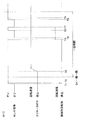
本体ケーシング2内への現像カートリッジ7の装着は、フロントカバー7が開かれた状態で行われる。新品の現像カートリッジ7が本体ケーシング2内に装着される場合、その装着の途中で、図3A〜3Cに示されるように、第2被検知部73の先端部73Aが干渉部材91の操作部93における傾斜した部分の上面に当接する。そして、その装着に伴う現像カートリッジ7の後方への移動により、第2被検知部73の先端部73Aは、操作部93の傾斜した部分の上面を摺擦しつつ、その傾斜に従って上方に持ち上げられる。これにより、被検知回転体50が図3B〜3Dにおける時計回りに約10°回転し(図12のT1−T2)、図3Dに示されるように、被係合部78が係合部66の回転軌跡上に配置される。   The developing cartridge 7 is mounted in the main casing 2 while the front cover 7 is opened. When a new developing cartridge 7 is mounted in the main casing 2, the tip end portion 73 </ b> A of the second detected portion 73 becomes the operating portion 93 of the interference member 91 as shown in FIGS. It contacts the upper surface of the inclined portion. Then, due to the backward movement of the developing cartridge 7 accompanying the mounting, the tip end portion 73A of the second detected portion 73 is lifted upward according to the inclination while rubbing the upper surface of the inclined portion of the operation portion 93. . As a result, the detected rotating body 50 rotates about 10 ° in the clockwise direction in FIGS. 3B to 3D (T1-T2 in FIG. 12), and as shown in FIG. Arranged on the rotation trajectory.

現像カートリッジ7の装着が完了すると、図3A〜3Cに示されるように、第1被検知部72の先端部がアクチュエータ94の当接レバー97の下端部に当接して、その下端部を後方へ押圧し、アクチュエータ94が検知姿勢となる。その結果、光センサ95の発光素子から受光素子に至る光路が遮光レバー98により遮られ、光センサ95からオン信号が出力される(図12のT1)。これにより、光センサ95による第1被検知部72の間接的な検出が達成される。   When the mounting of the developing cartridge 7 is completed, as shown in FIGS. 3A to 3C, the tip end portion of the first detected portion 72 comes into contact with the lower end portion of the contact lever 97 of the actuator 94, and the lower end portion is moved backward. By pressing, the actuator 94 becomes the detection posture. As a result, the optical path from the light emitting element to the light receiving element of the optical sensor 95 is blocked by the light shielding lever 98, and an ON signal is output from the optical sensor 95 (T1 in FIG. 12). Thereby, the indirect detection of the 1st to-be-detected part 72 by the optical sensor 95 is achieved.

なお、このときの被検知回転体50の回転位置が、第1被検知部72が光センサ95に検知される初期位置の一例である。   The rotational position of the detected rotating body 50 at this time is an example of the initial position at which the first detected unit 72 is detected by the optical sensor 95.

現像カートリッジ7の装着が完了し、フロントカバー4が閉じられると、レーザプリンタ1のウォームアップ動作が開始される。このウォームアップ動作では、入力ギヤ45の結合凹部55に駆動出力部材56(図2A参照)が挿入されて、駆動出力部材56から入力ギヤ45に駆動力が入力され、入力ギヤ45が回転する。そして、入力ギヤ45の回転に伴って、現像ギヤ46、供給ギヤ47および中間ギヤ48が回転し、現像ローラ18および供給ローラ19が回転する。また、中間ギヤ48の回転に伴って、アジテータギヤ49が回転し(図12のT3)、アジテータ16(図1参照)が回転する。このアジテータ16の回転により、現像カートリッジ7内のトナーがほぐされる。   When the mounting of the developing cartridge 7 is completed and the front cover 4 is closed, the warm-up operation of the laser printer 1 is started. In this warm-up operation, the drive output member 56 (see FIG. 2A) is inserted into the coupling recess 55 of the input gear 45, the drive force is input from the drive output member 56 to the input gear 45, and the input gear 45 rotates. As the input gear 45 rotates, the developing gear 46, the supply gear 47, and the intermediate gear 48 rotate, and the developing roller 18 and the supply roller 19 rotate. As the intermediate gear 48 rotates, the agitator gear 49 rotates (T3 in FIG. 12), and the agitator 16 (see FIG. 1) rotates. The rotation of the agitator 16 loosens the toner in the developing cartridge 7.

アジテータギヤ49は、図4C,5C,6Cにその回転位置が順に示されるように、図4C,5C,6Cにおける時計回りに回転する。このとき、係合部66と被係合部78とが接触しておらず、また、アジテータギヤ49の欠け歯ギヤ部69のギヤ歯76とアジテータギヤ49のギヤ歯67とが噛合していないので、図4A〜4D,5A〜5D,6A〜6Dに示されるように、被検知回転体50は回転せず、被検知回転体50の回転位置は変わらない。   The agitator gear 49 rotates clockwise in FIGS. 4C, 5C, and 6C so that the rotational positions thereof are sequentially shown in FIGS. 4C, 5C, and 6C. At this time, the engaging portion 66 and the engaged portion 78 are not in contact with each other, and the gear tooth 76 of the chipped gear portion 69 of the agitator gear 49 and the gear tooth 67 of the agitator gear 49 are not meshed with each other. Therefore, as shown in FIGS. 4A to 4D, 5A to 5D, and 6A to 6D, the detected rotating body 50 does not rotate, and the rotational position of the detected rotating body 50 does not change.

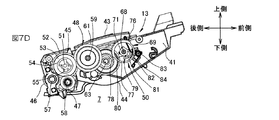
アジテータギヤ49の回転が進むと、図7A,7C,7Dに示されるように、係合部66が被係合部78に当接する。具体的には、図7Eに示されるように、係合部66が被係合部78に対して上方から当接する。   When the rotation of the agitator gear 49 proceeds, the engaging portion 66 contacts the engaged portion 78 as shown in FIGS. 7A, 7C, and 7D. Specifically, as shown in FIG. 7E, the engaging portion 66 contacts the engaged portion 78 from above.

そして、アジテータギヤ49の回転がさらに進むと、図8A,8C,8Dに示されるように、係合部66により被係合部78が押圧され、被検知回転体50が図8A,8C,8Dにおける反時計回りに回転し(図12のT4)、被検知回転体50の欠け歯ギヤ部69のギヤ歯76がアジテータギヤ49のギヤ歯67と噛合する。   When the rotation of the agitator gear 49 further proceeds, as shown in FIGS. 8A, 8C, and 8D, the engaged portion 78 is pressed by the engaging portion 66, and the detected rotating body 50 is moved to FIGS. 8A, 8C, and 8D. (T4 in FIG. 12), the gear teeth 76 of the chipped gear portion 69 of the detected rotating body 50 mesh with the gear teeth 67 of the agitator gear 49.

その後は、アジテータギヤ49の回転に従動して、ギヤ歯76が移動し、被検知回転体50が回転する。被検知回転体50の回転により、図9A〜9Cに示されるように、第1被検知部72の先端部がアクチュエータ94の当接レバー97から離れ、アクチュエータ94が検知姿勢から非検知姿勢となる。その結果、光センサ95の発光素子から受光素子に至る光路上から遮光レバー98が外れ、光センサ95からオフ信号が出力される(図12のT5)。   Thereafter, following the rotation of the agitator gear 49, the gear teeth 76 move, and the detected rotating body 50 rotates. 9A to 9C, the tip of the first detected portion 72 is separated from the contact lever 97 of the actuator 94, and the actuator 94 changes from the detection posture to the non-detection posture. . As a result, the light shielding lever 98 is removed from the optical path from the light emitting element to the light receiving element of the optical sensor 95, and an off signal is output from the optical sensor 95 (T5 in FIG. 12).

その後、アジテータギヤ49および被検知回転体50の回転が進むと、図10A〜10Cに示されるように、第3被検知部74の先端部がアクチュエータ94の当接レバー97の下端部に当接して、その下端部を後方へ押圧し、アクチュエータ94が非検知姿勢から再び検知姿勢となる。その結果、光センサ95の発光素子から受光素子に至る光路が遮光レバー98により遮られ、光センサ95からオン信号が出力される(図12のT6)。これにより、光センサ95による第3被検知部74の間接的な検出が達成される。   Thereafter, when the rotation of the agitator gear 49 and the detected rotating body 50 proceeds, the tip end portion of the third detected portion 74 comes into contact with the lower end portion of the contact lever 97 of the actuator 94 as shown in FIGS. The lower end of the actuator 94 is pushed rearward, and the actuator 94 changes from the non-detection posture to the detection posture again. As a result, the optical path from the light emitting element to the light receiving element of the optical sensor 95 is blocked by the light shielding lever 98, and an ON signal is output from the optical sensor 95 (T6 in FIG. 12). Thereby, the indirect detection of the 3rd to-be-detected part 74 by the optical sensor 95 is achieved.

アジテータギヤ49および被検知回転体50の回転がさらに進むと、第3被検知部74の先端部がアクチュエータ94の当接レバー97から離れ、アクチュエータ94が検知姿勢から再び非検知姿勢となる。その結果、光センサ95の発光素子から受光素子に至る光路上から遮光レバー98が外れ、光センサ95からオフ信号が出力される(図12のT7)。   When the rotation of the agitator gear 49 and the detected rotating body 50 further proceeds, the tip end portion of the third detected portion 74 moves away from the contact lever 97 of the actuator 94, and the actuator 94 changes from the detection posture to the non-detection posture again. As a result, the light shielding lever 98 is removed from the optical path from the light emitting element to the light receiving element of the optical sensor 95, and an off signal is output from the optical sensor 95 (T7 in FIG. 12).

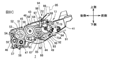
この後、アジテータギヤ49および被検知回転体50の回転がさらに進むと、図11A〜11Cに示されるように、第2被検知部73の先端部73Aがアクチュエータ94の当接レバー97の下端部に当接して、その下端部を後方へ押圧し、アクチュエータ94が非検知姿勢から再び検知姿勢となる。その結果、光センサ95の発光素子から受光素子に至る光路が遮光レバー98により遮られ、光センサ95からオン信号が出力される(図12のT8)。これにより、光センサ95による第2被検知部73の間接的な検出が達成される。   Thereafter, when the rotation of the agitator gear 49 and the detected rotating body 50 further proceeds, as shown in FIGS. 11A to 11C, the distal end portion 73A of the second detected portion 73 becomes the lower end portion of the contact lever 97 of the actuator 94. , The lower end of the actuator 94 is pressed backward, and the actuator 94 changes from the non-detection posture to the detection posture again. As a result, the optical path from the light emitting element to the light receiving element of the optical sensor 95 is blocked by the light shielding lever 98, and an ON signal is output from the optical sensor 95 (T8 in FIG. 12). Thereby, the indirect detection of the 2nd to-be-detected part 73 by the optical sensor 95 is achieved.

そして、図11Dに示されるように、アジテータギヤ49および被検知回転体50の回転がさらに進み、被検知回転体50のギヤ歯76がアジテータギヤ49のギヤ歯67との噛合が解除されると、被検知回転体50の回転が停止する(図12のT9)。その後は、線ばね84が被検知回転体50の被押圧部79を後方に向けて押圧することにより、被検知回転体50の回転位置がギヤ歯76とギヤ歯67との噛合が解除された時の回転位置に保持され、被検知回転体50が回転することはない。   Then, as shown in FIG. 11D, when the rotation of the agitator gear 49 and the detected rotating body 50 further proceeds and the meshing of the gear teeth 76 of the detected rotating body 50 with the gear teeth 67 of the agitator gear 49 is released. Then, the rotation of the detected rotating body 50 stops (T9 in FIG. 12). Thereafter, the wire spring 84 presses the pressed portion 79 of the detected rotating body 50 toward the rear, so that the rotational position of the detected rotating body 50 is disengaged from the gear teeth 76 and the gear teeth 67. The detected rotation body 50 is not rotated by being held at the rotation position at the time.

フロントカバー7が閉じられてから一定時間が経過すると、ウォームアップ動作が終了となり、駆動出力部材56を回転させるモータ(図示せず)が停止されて、駆動出力部材56から入力ギヤ45への駆動力の入力が停止する。   When a certain period of time has elapsed after the front cover 7 is closed, the warm-up operation is terminated, the motor (not shown) that rotates the drive output member 56 is stopped, and driving from the drive output member 56 to the input gear 45 is performed. Force input stops.

このように、新品の現像カートリッジ7が本体ケーシング2に初めて装着されると、光センサ95からオフ信号が出力される状態が2回生じる。したがって、現像カートリッジ2が本体ケーシング2に装着された後、光センサ95からオフ信号が出力される状態が2回生じた場合には、その現像カートリッジ2が新品であると判断することができる。   As described above, when a new developing cartridge 7 is first attached to the main casing 2, a state where an off signal is output from the optical sensor 95 occurs twice. Therefore, when the state where the OFF signal is output from the optical sensor 95 occurs twice after the developing cartridge 2 is mounted on the main casing 2, it can be determined that the developing cartridge 2 is new.

さらに、現像カートリッジ7が新品である場合には、現像カートリッジ7が本体ケーシング2内に装着されると、第1被検知部72の先端部がアクチュエータ94の当接レバー97の下端部を後方へ押圧し、アクチュエータ94が検知姿勢となり、光センサ95からオン信号が出力される。また、現像カートリッジ7が旧品であっても、現像カートリッジ7が本体ケーシング2内に装着されると、第2被検知部73の先端部73Aがアクチュエータ94の当接レバー97の下端部を後方へ押圧し、アクチュエータ94が検知姿勢となり、光センサ95からオン信号が出力される。よって、現像カートリッジ7が新品であるか旧品であるかにかかわらず、現像カートリッジ7が本体ケーシング2内に装着された状態では、光センサ95からオン信号が出力されるので、これに基づいて、本体ケーシング2内に現像カートリッジ7が装着されているか否かを判別することができる。   Further, when the developing cartridge 7 is new, when the developing cartridge 7 is mounted in the main casing 2, the tip of the first detected portion 72 moves the lower end of the contact lever 97 of the actuator 94 backward. The actuator 94 is in a detection posture, and an ON signal is output from the optical sensor 95. Even if the developing cartridge 7 is an old product, when the developing cartridge 7 is mounted in the main casing 2, the distal end portion 73 </ b> A of the second detected portion 73 moves the lower end portion of the contact lever 97 of the actuator 94 backward. The actuator 94 is in a detection posture, and an ON signal is output from the optical sensor 95. Therefore, regardless of whether the developing cartridge 7 is a new product or an old product, an ON signal is output from the optical sensor 95 when the developing cartridge 7 is mounted in the main casing 2. It can be determined whether or not the developing cartridge 7 is mounted in the main casing 2.

なお、第3被検知部74は、省略されてもよい。第3被検知部74が省略される場合、新品の現像カートリッジ2が本体ケーシング2に装着されると、図13に示すように、時間T6−T7において光センサ95からオン信号が出力されず、光センサ95からオフ信号が出力される状態が1回のみ生じる。したがって、光センサ95からオフ信号が出力される状態が1回生じたことにより、その現像カートリッジ2が新品であると判別することができる。   Note that the third detected portion 74 may be omitted. When the third detected portion 74 is omitted, when a new developing cartridge 2 is mounted on the main casing 2, an on signal is not output from the optical sensor 95 at time T <b> 6-T <b> 7, as shown in FIG. 13. A state in which an off signal is output from the optical sensor 95 occurs only once. Therefore, it can be determined that the developing cartridge 2 is new when the state in which the off signal is output from the optical sensor 95 occurs once.

たとえば、第3被検知部74が設けられている現像カートリッジ2の筐体13内には、トナーが相対的に多量に収容され、第3被検知部74が省略された現像カートリッジ2の筐体13内には、トナーが相対的に少量に収容されて、これらが選択的に本体ケーシング2内に装着される場合、新品の現像カートリッジ2が装着された後に、光センサ95からオフ信号が出力される状態が生じた回数により、その現像カートリッジ7の種別を判別することができる。   For example, a relatively large amount of toner is accommodated in the housing 13 of the developing cartridge 2 in which the third detected portion 74 is provided, and the housing of the developing cartridge 2 in which the third detected portion 74 is omitted. 13 contains a relatively small amount of toner, and when these are selectively mounted in the main casing 2, an off signal is output from the optical sensor 95 after the new developing cartridge 2 is mounted. The type of the developing cartridge 7 can be determined based on the number of occurrences of the developed state.

このような現像カートリッジ7の装着の有無および現像カートリッジ7の新旧の判別は、マイクロコンピュータを備える制御部(図示せず)により行われる。具体的には、現像カートリッジ7の装着の有無および現像カートリッジ7の新旧の判別のために、制御部により、たとえば、図18のフローチャートに示される処理が実行される。   Whether the developing cartridge 7 is mounted or not and whether the developing cartridge 7 is new or old is determined by a control unit (not shown) including a microcomputer. Specifically, for example, the processing shown in the flowchart of FIG. 18 is executed by the control unit in order to determine whether or not the developing cartridge 7 is mounted and whether the developing cartridge 7 is new or old.

図18のフローチャートは、フロントカバー7が閉じられたことに応答して実行される。   The flowchart of FIG. 18 is executed in response to the front cover 7 being closed.

フロントカバー7が閉じられると、まず、光センサ95の出力信号がオン信号(ON)であるか否かが調べられる(S1)。   When the front cover 7 is closed, it is first checked whether or not the output signal of the optical sensor 95 is an ON signal (ON) (S1).

光センサ95の出力信号がオン信号であれば(S1:YES)、ウォームアップ動作が開始され、入力ギヤ45の結合凹部55に駆動出力部材56が結合した状態で、駆動出力部材56を回転させるためのモータ(図示せず)の駆動が開始される(S2)。   If the output signal of the optical sensor 95 is an ON signal (S1: YES), the warm-up operation is started and the drive output member 56 is rotated in a state where the drive output member 56 is coupled to the coupling recess 55 of the input gear 45. The driving of a motor (not shown) is started (S2).

モータの駆動中は、光センサ95の出力信号の状態が常に監視されている(S3)。すなわち、制御部により、光センサ95の出力信号が一定周期でサンプリングされ、光センサ95の出力信号がオン信号であるかオフ信号であるかが繰り返し調べられている。光センサ95の出力信号がオン信号からオフ信号に切り替わると、その度に制御部内のカウンタの値がインクリメント(+1)される。カウンタの値は、この処理の開始時に零にリセットされている。   While the motor is being driven, the state of the output signal of the optical sensor 95 is constantly monitored (S3). That is, the control unit samples the output signal of the optical sensor 95 at a constant cycle, and repeatedly checks whether the output signal of the optical sensor 95 is an on signal or an off signal. Each time the output signal of the optical sensor 95 is switched from the on signal to the off signal, the value of the counter in the control unit is incremented (+1). The counter value is reset to zero at the start of this process.

モータの駆動開始から一定時間が経過すると(S4:YES)、モータの駆動が停止され、ウォームアップ動作が終了となる。   When a certain time has elapsed from the start of motor driving (S4: YES), the motor driving is stopped and the warm-up operation ends.

そして、モータが駆動されていた期間(モニタ期間)における光センサ95からのオフ信号の出力の有無が調べられる(S5)。具体的には、制御部内のカウンタの値が1または2であるか零であるかが調べられる。   Then, it is checked whether or not an off signal is output from the optical sensor 95 during the period in which the motor is driven (monitoring period) (S5). Specifically, it is checked whether the value of the counter in the control unit is 1 or 2 or zero.

カウンタの値が1または2であれば、現像カートリッジ7が新品であると判別される(S6)。より詳細な一例では、カウンタの値が1であれば、現像カートリッジ7が新品かつ相対的に少ない量のトナーを収容したものであると判別され、カウンタの値が2であれば、現像カートリッジ7が新品かつ相対的に多い量のトナーを収容したものであると判別される。   If the value of the counter is 1 or 2, it is determined that the developing cartridge 7 is new (S6). In a more detailed example, if the counter value is 1, it is determined that the developing cartridge 7 is new and contains a relatively small amount of toner, and if the counter value is 2, the developing cartridge 7 Is new and contains a relatively large amount of toner.

一方、カウンタの値が零であれば、現像カートリッジ7が旧品であると判別される(S7)。   On the other hand, if the value of the counter is zero, it is determined that the developing cartridge 7 is an old product (S7).

また、フロントカバー7が閉じられた直後の光センサ95の出力信号がオフ信号である場合(S1:NO)、本体ケーシング2内に現像カートリッジ7が装着されていないと判別される(S8)。
6.作用効果
(1)作用効果1
以上のように、筺体13の第1側壁41の外側には、入力ギヤ45および被検知回転体50がそれぞれ互いに平行に延びる入力ギヤ回転軸51および回転軸68の各中心軸線を中心に回転可能に設けられている。入力ギヤ回転軸51および回転軸68の中心軸線は、それぞれ第1軸線および第3軸線の一例である。また、第1側壁41と第2側壁42との間には、現像ローラ18が現像回転軸線20を中心に回転可能に設けられている。
If the output signal of the optical sensor 95 immediately after the front cover 7 is closed is an off signal (S1: NO), it is determined that the developing cartridge 7 is not mounted in the main casing 2 (S8).
6). Function and Effect (1) Function and Effect 1
As described above, on the outside of the first side wall 41 of the housing 13, the input gear 45 and the detected rotating body 50 can rotate around the central axes of the input gear rotating shaft 51 and the rotating shaft 68 extending in parallel with each other. Is provided. The center axes of the input gear rotation shaft 51 and the rotation shaft 68 are examples of the first axis and the third axis, respectively. Further, the developing roller 18 is provided between the first side wall 41 and the second side wall 42 so as to be rotatable about the developing rotation axis 20.

入力ギヤ45には、本体ケーシング2内に備えられた駆動出力部材56が接続されて、駆動出力部材56から駆動力が入力される。この入力ギヤ45に入力される駆動力(入力ギヤ45が駆動出力部材56から受ける駆動力)により、現像ローラ18が回転する。   A drive output member 56 provided in the main casing 2 is connected to the input gear 45, and a drive force is input from the drive output member 56. The developing roller 18 is rotated by the driving force input to the input gear 45 (the driving force received by the input gear 45 from the drive output member 56).

被検知回転体50は、第1被検知部72および第2被検知部73を有している。第2被検知部73は、現像カートリッジ7が本体ケーシング2内に装着される過程において、本体ケーシング2内に固定的に配置された干渉部材91に接触する。これにより、被検知回転体50は、図2A〜2Dに示される回転位置である退避位置から、図3A〜3Dに示される回転位置である初期位置まで回転する。その結果、被検知回転体50が入力ギヤ45からの駆動力により回転可能な状態(係合部66が被係合部78に当接可能な状態)となる。   The detected rotating body 50 includes a first detected unit 72 and a second detected unit 73. The second detected portion 73 contacts the interference member 91 that is fixedly disposed in the main casing 2 in the process in which the developing cartridge 7 is mounted in the main casing 2. Accordingly, the detected rotating body 50 rotates from the retracted position that is the rotational position shown in FIGS. 2A to 2D to the initial position that is the rotational position shown in FIGS. As a result, the detected rotating body 50 can be rotated by the driving force from the input gear 45 (the engaging portion 66 can contact the engaged portion 78).

そして、現像カートリッジ7が本体ケーシング2内に装着される前においては、被検知回転体50の回転位置が退避位置であり、被検知回転体50は、入力ギヤ45から駆動が切り離され、入力ギヤ45が受ける駆動力により回転しない。   Before the developing cartridge 7 is mounted in the main casing 2, the rotational position of the detected rotating body 50 is the retracted position, and the detected rotating body 50 is disconnected from the input gear 45 and the input gear 45 is driven. It does not rotate due to the driving force that 45 receives.

現像カートリッジ7の製造ラインにおいて、現像カートリッジ7の組立後に、現像カートリッジ7の動作確認が行われることがある。この動作確認のために入力ギヤ45に駆動力が入力され、これにより被検知回転体50が回転すると、被検知回転体50の回転位置が適正な位置から外れるため、現像カートリッジ7に関する情報が誤って取得されるおそれがある。たとえば、現像カートリッジ7の動作確認時に、被検知回転体50が図11B,11Cに示される回転位置を越える回転位置まで回転されると、現像カートリッジ7が新品であるか旧品であるかの判別さえも不可能となる。すなわち、新品の現像カートリッジ7であっても、本体ケーシング2内に装着されたときに、光センサ95からオフ信号が1度も出力されず、現像カートリッジ7が旧品であると判定されてしまうおそれがある。   In the production line of the developing cartridge 7, the operation of the developing cartridge 7 may be confirmed after the assembling of the developing cartridge 7. When the driving force is input to the input gear 45 to check the operation and the detected rotating body 50 rotates as a result, the rotational position of the detected rotating body 50 deviates from the proper position. May be acquired. For example, when the detected rotating body 50 is rotated to a rotational position exceeding the rotational position shown in FIGS. 11B and 11C when the operation of the developing cartridge 7 is confirmed, it is determined whether the developing cartridge 7 is a new product or an old product. Even impossible. That is, even if it is a new developing cartridge 7, when it is mounted in the main body casing 2, an off signal is not output from the optical sensor 95, and it is determined that the developing cartridge 7 is an old product. There is a fear.

被検知回転体50の回転位置が退避位置であるときには、入力ギヤ45に駆動力が入力されても、被検知回転体50が回転しないので、現像カートリッジ7の組立後に、被検知回転体50を回転させることなく、現像カートリッジ7の動作確認を行うことができる。したがって、現像カートリッジ7の動作確認が行われても、被検知回転体50が意図しない位置に回転することがない。そのため、動作確認後においても、被検知回転体50の第1被検知部72、第2被検知部73および第3被検知部74が適正な位置に維持される。そのため、現像カートリッジ7が本体ケーシング2内に装着された後に、光センサ95により第1被検知部72を検知することができ、これに基づいて、現像カートリッジ7に関する情報(現像カートリッジ7の装着の有無)を良好に取得することができる。   When the rotational position of the detected rotating body 50 is the retracted position, the detected rotating body 50 does not rotate even if a driving force is input to the input gear 45. The operation of the developing cartridge 7 can be confirmed without rotating. Therefore, even if the operation of the developing cartridge 7 is confirmed, the detected rotating body 50 does not rotate to an unintended position. Therefore, even after the operation is confirmed, the first detected portion 72, the second detected portion 73, and the third detected portion 74 of the detected rotating body 50 are maintained at appropriate positions. Therefore, after the developing cartridge 7 is mounted in the main casing 2, the first detected portion 72 can be detected by the optical sensor 95, and based on this information (information regarding the mounting of the developing cartridge 7). Presence / absence) can be acquired well.

よって、現像カートリッジ7は、被検知回転体50を備えながら、従来の現像カートリッジよりも便利である。   Therefore, the developing cartridge 7 is more convenient than the conventional developing cartridge while including the detected rotating body 50.

また、第1被検知部72と第2被検知部73とが分けて形成されているので、これらが同一部として形成された構成と比較して、第1被検知部72の摩耗ならびに第1被検知部72および第2被検知部73の各位置精度の点で優れている。   Further, since the first detected part 72 and the second detected part 73 are formed separately, the wear of the first detected part 72 and the first are compared with the configuration in which these parts are formed as the same part. It is excellent in terms of positional accuracy of the detected part 72 and the second detected part 73.

すなわち、第1被検知部72が第2被検知部73を兼ねていると、第1被検知部72が本体ケーシング2内の干渉部材91との接触により摩耗するおそれがある。第1被検知部72が摩耗すると、第1被検知部72とアクチュエータ94の当接レバー97との当接状態が不安定となり、光センサ95による第1被検知部72の検知精度が低下するおそれがある。第1被検知部72と第2被検知部73とが別々に形成されていれば、干渉部材91との接触による第1被検知部72の磨耗がないので、光センサ95による第1被検知部72の良好な検知を達成することができる。   That is, if the first detected part 72 also serves as the second detected part 73, the first detected part 72 may be worn by contact with the interference member 91 in the main body casing 2. When the first detected part 72 is worn, the contact state between the first detected part 72 and the contact lever 97 of the actuator 94 becomes unstable, and the detection accuracy of the first detected part 72 by the optical sensor 95 decreases. There is a fear. If the first detected portion 72 and the second detected portion 73 are formed separately, the first detected portion 72 due to contact with the interference member 91 is not worn, so the first detected by the optical sensor 95 is detected. Good detection of the part 72 can be achieved.

また、第1被検知部72および第2被検知部73の各部の機能が良好に発揮されるように、それらの配置を個別に決定して、第1被検知部72および第2被検知部73をその決定した各位置に精度よく配置することができる。その結果、光センサ95による第1被検知部72の良好な検知および第2被検知部73と干渉部材91との良好な接触を達成することができる。
(2)作用効果2
第1側壁41の外側には、アジテータギヤ49が第4軸線、第5軸線および第6軸線の一例としてのアジテータ回転軸62の中心軸線を中心に回転可能に設けられている。アジテータギヤ49は、入力ギヤ45が受ける駆動力により回転する。アジテータギヤ49には、係合部66が形成されている。
Further, the arrangement of the first detected unit 72 and the second detected unit 73 is determined individually so that the functions of the first detected unit 72 and the second detected unit 73 are performed well. 73 can be accurately placed at each determined position. As a result, good detection of the first detected portion 72 by the optical sensor 95 and good contact between the second detected portion 73 and the interference member 91 can be achieved.
(2) Action effect 2
An agitator gear 49 is provided outside the first side wall 41 so as to be rotatable about a central axis of an agitator rotation shaft 62 as an example of a fourth axis, a fifth axis, and a sixth axis. The agitator gear 49 is rotated by the driving force received by the input gear 45. An engaging portion 66 is formed in the agitator gear 49.

一方、被検知回転体50は、被係合部78を有している。被係合部78は、被検知回転体50の回転時に描く回転軌跡が係合部66が描く回転軌跡と一部重なるように設けられている。   On the other hand, the detected rotating body 50 has an engaged portion 78. The engaged portion 78 is provided so that the rotation locus drawn when the detected rotating body 50 rotates partially overlaps the rotation locus drawn by the engaging portion 66.

被検知回転体50の回転位置が退避位置であるときには、被係合部78は、係合部66の回転軌跡外に配置されている。したがって、この状態でアジテータギヤ49(係合部66)が回転しても、係合部66が被係合部78に係合しない。そして、被検知回転体50が退避位置から初期位置まで回転すると、被係合部78が係合部66の回転軌跡上に配置される。この状態で、アジテータギヤ49が回転すると、係合部66が被係合部78に係合し、係合部66から被係合部78に力が加えられて、被検知回転体50が回転する。   When the rotation position of the detected rotating body 50 is the retracted position, the engaged portion 78 is disposed outside the rotation locus of the engaging portion 66. Therefore, even if the agitator gear 49 (engaging portion 66) rotates in this state, the engaging portion 66 does not engage with the engaged portion 78. When the detected rotating body 50 rotates from the retracted position to the initial position, the engaged portion 78 is disposed on the rotation locus of the engaging portion 66. When the agitator gear 49 rotates in this state, the engaging portion 66 engages with the engaged portion 78, and force is applied from the engaging portion 66 to the engaged portion 78, so that the detected rotating body 50 rotates. To do.

よって、係合部66および被係合部78を含む簡素な構成により、被検知回転体50の回転位置が退避位置であるときには、確実に、入力ギヤ45が受ける駆動力により被検知回転体50が回転しない状態とすることができる。そして、被検知回転体50が退避位置から初期位置まで回転されたときに、確実に、入力ギヤ45が受ける駆動力により被検知回転体50が回転する状態にすることができる。
(3)作用効果3
アジテータギヤ49の小径ギヤ部65の周面には、ギヤ歯67が形成されている。
Therefore, with the simple configuration including the engaging portion 66 and the engaged portion 78, when the rotational position of the detected rotating body 50 is the retracted position, the detected rotating body 50 is surely received by the driving force received by the input gear 45. Can be in a non-rotating state. When the detected rotating body 50 is rotated from the retracted position to the initial position, the detected rotating body 50 can be reliably rotated by the driving force received by the input gear 45.
(3) Effect 3
Gear teeth 67 are formed on the peripheral surface of the small diameter gear portion 65 of the agitator gear 49.

一方、被検知回転体50の欠け歯ギヤ部69の周面には、一部を欠け歯部分77として、欠け歯部分77以外の部分に、ギヤ歯67と噛合可能なギヤ歯76が形成されている。   On the other hand, on the peripheral surface of the missing tooth gear portion 69 of the detected rotating body 50, a gear tooth 76 that can mesh with the gear tooth 67 is formed in a portion other than the missing tooth portion 77 as a part of the missing tooth portion 77. ing.

そして、被検知回転体50の回転位置が退避位置および初期位置であるときに、被検知回転体50の欠け歯部分77がアジテータギヤ49のギヤ歯67に対向する。そのため、被検知回転体50の回転位置が退避位置および初期位置であるときには、入力ギヤ45が受ける駆動力により、アジテータギヤ49が回転しても、直ちには、被検知回転体50のギヤ歯76がアジテータギヤ49のギヤ歯67と噛合しない。よって、被検知回転体50の回転位置が退避位置および初期位置であるときに、被検知回転体50がアジテータギヤ49の回転に直ちに従動して回転することを防止できる。
(4)作用効果4
現像カートリッジ7には、アジテータ16が備えられている。そのため、アジテータ16により、筺体13内に収容されているトナーを攪拌することができる。
When the rotational position of the detected rotating body 50 is the retracted position and the initial position, the missing tooth portion 77 of the detected rotating body 50 faces the gear teeth 67 of the agitator gear 49. Therefore, when the rotational position of the detected rotating body 50 is the retracted position and the initial position, even if the agitator gear 49 is rotated by the driving force received by the input gear 45, the gear teeth 76 of the detected rotating body 50 are immediately used. Does not mesh with the gear teeth 67 of the agitator gear 49. Therefore, when the rotational position of the detected rotating body 50 is the retracted position and the initial position, it is possible to prevent the detected rotating body 50 from being immediately driven by the rotation of the agitator gear 49 and rotating.
(4) Action effect 4
The developing cartridge 7 is provided with an agitator 16. Therefore, the toner contained in the housing 13 can be agitated by the agitator 16.

新品の現像カートリッジ7では、筐体13内のトナーが固まっている場合がある。この場合、新品の現像カートリッジ7が本体ケーシング2内に装着されて、入力ギヤ45が駆動出力部材56から受ける駆動力によりアジテータギヤ49が回転し始めた直後は、アジテータギヤ49と一体的に回転するアジテータ16に大きな負荷(抵抗)が加わる。そして、トナーがほぐれ始めると、アジテータ16に加わる負荷が小さくなり、その負荷の大きさがほぼ一定に落ち着く。したがって、アジテータギヤ49が回転し始めてからトナーがほぐれるまでの間は、アジテータギヤ49の回転が不安定になる。   In the new developing cartridge 7, the toner in the housing 13 may be hardened. In this case, immediately after the new developing cartridge 7 is mounted in the main casing 2 and the agitator gear 49 starts to rotate by the driving force received by the input gear 45 from the driving output member 56, the developing cartridge 7 rotates integrally with the agitator gear 49. A large load (resistance) is applied to the agitator 16 to be operated. When the toner starts to loosen, the load applied to the agitator 16 becomes small, and the magnitude of the load settles almost constant. Accordingly, the rotation of the agitator gear 49 becomes unstable after the agitator gear 49 starts rotating until the toner is loosened.

被検知回転体50は、駆動出力部材56の始動直後(入力ギヤ45への駆動力の入力開始直後)は、アジテータギヤ49の回転に従動せず、駆動出力部材56の始動から係合部66が被係合部78に係合するまでに要する時間が経過した後、アジテータギヤ49の回転に従動する。よって、筐体内のトナーがほぐれた後に、被検知回転体50をアジテータギヤ49の回転に従動させることができる。その結果、被検知回転体50の回転を一層安定させることができ、第1被検知部72をより安定した速度で移動させることができる。   The detected rotating body 50 does not follow the rotation of the agitator gear 49 immediately after the drive output member 56 is started (immediately after the drive force input to the input gear 45 is started). After the time required for engaging the engaged portion 78, the rotation of the agitator gear 49 is followed. Therefore, the detected rotating body 50 can be driven by the rotation of the agitator gear 49 after the toner in the casing is loosened. As a result, the rotation of the detected rotating body 50 can be further stabilized, and the first detected portion 72 can be moved at a more stable speed.

また、筺体13内のトナーが固まっていない場合でも、駆動出力部材56の始動直後は、その駆動出力部材56から入力ギヤ45に入力される駆動力の大きさが不安定である。したがって、駆動出力部材56の始動から係合部66が被係合部78に係合するまでに要する時間が経過した後に、被検知回転体50が回転し始めることにより、被検知回転体50を安定した大きさの駆動力により回転させることができ、第1被検知部72をより一層安定した速度で移動させることができる。
(5)作用効果5
第1被検知部72および第2被検知部73は、被検知回転体50の回転半径方向に延びている。第2被検知部73は、被検知回転体50の回転時に第1被検知部72が描く回転軌跡外に突出し、その突出する先端部73Aは、本体ケーシング2内への現像カートリッジ7の装着時に干渉部材91が当接する被当接部とされている。これにより、第2被検知部73に干渉部材91を確実に当接させることができながら、被検知回転体50の回転時に、第1被検知部72が干渉部材91に当接することを防止できる。
(6)作用効果6
また、第1被検知部72と第2被検知部73とが被検知回転体50の回転方向に互いに離れて配置されているので、被検知回転体50が360°回転しなくても、その回転位置が第1被検知部72が光センサ95に検知される初期位置から第2被検知部73が光センサ95に検知される位置に変位する。そのため、被検知回転体50が欠け歯ギヤ部69を備えることにより、第2被検知部73が光センサ95に検知される位置まで被検知回転体50が回転したときに、アジテータギヤ49から被検知回転体50への駆動力の伝達を遮断することができながら、第1被検知部72および第2被検知部73を備えることにより、被検知回転体50を360°回転させずに、光センサ95による第1被検知部72および第2被検知部73の検知を達成することができる。
Even if the toner in the housing 13 is not solidified, the magnitude of the driving force input from the driving output member 56 to the input gear 45 is unstable immediately after the driving output member 56 is started. Therefore, after the time required from when the drive output member 56 is started until the engaging portion 66 is engaged with the engaged portion 78 has elapsed, the detected rotating body 50 starts to rotate, so that the detected rotating body 50 is moved. It can be rotated by a driving force having a stable magnitude, and the first detected portion 72 can be moved at a more stable speed.
(5) Action effect 5
The first detected portion 72 and the second detected portion 73 extend in the rotational radius direction of the detected rotating body 50. The second detected portion 73 protrudes out of the rotation locus drawn by the first detected portion 72 when the detected rotating body 50 rotates, and the protruding tip 73A is when the developing cartridge 7 is mounted in the main casing 2. It is set as the to-be-contacted part which the interference member 91 contacts. Thereby, while the interference member 91 can be reliably brought into contact with the second detected portion 73, the first detected portion 72 can be prevented from coming into contact with the interference member 91 when the detected rotating body 50 is rotated. .
(6) Action effect 6
Further, since the first detected unit 72 and the second detected unit 73 are arranged away from each other in the rotation direction of the detected rotating body 50, even if the detected rotating body 50 does not rotate 360 °, The rotational position is shifted from the initial position where the first detected portion 72 is detected by the optical sensor 95 to the position where the second detected portion 73 is detected by the optical sensor 95. For this reason, since the detected rotating body 50 includes the chipped gear portion 69, when the detected rotating body 50 rotates to a position where the second detected portion 73 is detected by the optical sensor 95, the agitator gear 49 detects the detected rotating body 50. While the transmission of the driving force to the detection rotating body 50 can be interrupted, the first detected portion 72 and the second detected portion 73 are provided, so that the detected rotating body 50 is rotated without rotating 360 °. Detection of the first detected part 72 and the second detected part 73 by the sensor 95 can be achieved.

たとえば、第2被検知部73を省略して、光センサ95による第1被検知部72の検知のみにより、現像カートリッジ7が新品であるか否かの判別と、現像カートリッジ7が本体ケーシング2内に装着されているか否かの判別との両方を行うことが考えられる。   For example, the second detected portion 73 is omitted, and it is determined whether or not the developing cartridge 7 is new by only detecting the first detected portion 72 by the optical sensor 95, and the developing cartridge 7 is in the main casing 2. It is conceivable to perform both of the determination as to whether or not it is attached to the camera.

この場合、新品の現像カートリッジ7が本体ケーシング2内に装着された時点で、第1被検知部72がアクチュエータ94の当接レバー97に当接し、第1被検知部72が光センサ95により検知される必要がある。そして、被検知回転体50の回転により、第1被検知部72が当接レバー97から一旦離れた後、被検知回転体50が現像カートリッジ7の装着時から360°回転して、第1被検知部72が当接レバー97に再び当接し、第1被検知部72が光センサ95により検知される必要がある。さらに、被検知回転体50が360°回転した時点で、アジテータギヤ49から被検知回転体50への駆動力の伝達を遮断しなければならない。   In this case, when a new developing cartridge 7 is mounted in the main casing 2, the first detected portion 72 comes into contact with the contact lever 97 of the actuator 94, and the first detected portion 72 is detected by the optical sensor 95. Need to be done. Then, after the first detected portion 72 is once separated from the contact lever 97 by the rotation of the detected rotating body 50, the detected rotating body 50 rotates 360 ° from the time when the developing cartridge 7 is mounted, and the first detected section 72 is rotated. The detection unit 72 needs to contact the contact lever 97 again, and the first detected unit 72 needs to be detected by the optical sensor 95. Furthermore, transmission of the driving force from the agitator gear 49 to the detected rotating body 50 must be interrupted when the detected rotating body 50 rotates 360 °.

これら3つの要件は、欠け歯ギヤ部69を備える構成では満たすことができず、それらの要件を満たすためには、クラッチ機構などの複雑な機構を備えなければならず、現像カートリッジ7(レーザプリンタ1)の構成が複雑になるうえ、そのコストが増大する。   These three requirements cannot be satisfied by the configuration including the chipped gear portion 69, and in order to satisfy these requirements, a complicated mechanism such as a clutch mechanism must be provided, and the developing cartridge 7 (laser printer) The structure of 1) becomes complicated and the cost increases.

第1被検知部72と別に第2被検知部73を備え、欠け歯ギヤ部69を備えることにより、現像カートリッジ7の構成の複雑化およびコストの増大を押さえることができながら、現像カートリッジ7の新品/旧品および本体ケーシング2内における現像カートリッジ7の装着の有無を良好に判別するための3つの要件を満たすことができる。
7.変形例
(1)変形例1
レーザプリンタ1では、アジテータギヤ49の小径ギヤ部65に係合部66が一体的に形成されている。しかしながら、図14に示すように、小径ギヤ部65と別部材として、たとえば、円柱状の結合部材141が設けられて、この結合部材141に係合部66がその周面から突出するように形成され、結合部材141が小径ギヤ部65に対して一体的に回転可能なように(相対回転不能に)結合されていてもよい。
Since the second detected portion 73 is provided separately from the first detected portion 72 and the chipped gear portion 69 is provided, the configuration of the developing cartridge 7 and the increase in cost can be suppressed, while the developing cartridge 7 can be reduced. It is possible to satisfy three requirements for favorably discriminating whether the developing cartridge 7 is installed in the new / old product and the main casing 2.
7). Modification (1) Modification 1
In the laser printer 1, the engaging portion 66 is integrally formed with the small diameter gear portion 65 of the agitator gear 49. However, as shown in FIG. 14, for example, a cylindrical coupling member 141 is provided as a separate member from the small-diameter gear portion 65, and the engaging portion 66 is formed on the coupling member 141 so as to protrude from the peripheral surface. The coupling member 141 may be coupled to the small-diameter gear portion 65 so as to be integrally rotatable (non-relatively rotatable).

この場合、小径ギヤ部65と結合部材141とは、図14に示されるように、たとえば、結合部材141において小径ギヤ部65側に延びる2つのボス142を小径ギヤ部65に設けられた凹部143に嵌め合わせることにより、一体的に回転することが可能になる。
(2)変形例2
また、図15に示すように、係合部66は、中間ギヤ48から駆動力が伝達される別のギヤ151にその先端がギヤ151の周面から突出するように形成され、ギヤ151の回転により被係合部78を押圧してもよい。この場合、被検知回転体50は、まず、ギヤ151に設けられた係合部66と被係合部78と接触することにより、欠け歯ギヤ部69がアジテータ49の小径ギヤ部65から駆動を受ける位置に回転することになる。
(3)変形例3
第1被検知部72と第2被検知部73とは、一体化されていてもよい。たとえば、図16に示すように、第1被検知部72と第3被検知部74との間および第3被検知部74と第2被検知部73との間に、それぞれ円筒部71の外周面に沿って延びる非検知部の一例としての連結部161,162が形成されて、第1被検知部72、第2被検知部73および第3被検知部74が一体化されていてもよい。
In this case, as shown in FIG. 14, the small-diameter gear portion 65 and the coupling member 141 include, for example, a recess 143 provided in the small-diameter gear portion 65 with two bosses 142 extending toward the small-diameter gear portion 65 in the coupling member 141. It is possible to rotate as a whole by fitting together.
(2) Modification 2
Further, as shown in FIG. 15, the engaging portion 66 is formed on another gear 151 to which the driving force is transmitted from the intermediate gear 48 so that its tip protrudes from the peripheral surface of the gear 151, and the rotation of the gear 151. The engaged portion 78 may be pressed by the above. In this case, the detected rotating body 50 first drives the chipped gear portion 69 from the small-diameter gear portion 65 of the agitator 49 by contacting the engaging portion 66 and the engaged portion 78 provided on the gear 151. It will rotate to the receiving position.
(3) Modification 3
The first detected unit 72 and the second detected unit 73 may be integrated. For example, as shown in FIG. 16, the outer periphery of the cylindrical portion 71 is between the first detected portion 72 and the third detected portion 74 and between the third detected portion 74 and the second detected portion 73, respectively. The connection parts 161 and 162 as an example of the non-detection part extending along the surface may be formed, and the first detection part 72, the second detection part 73, and the third detection part 74 may be integrated. .

この場合、検知回転体50が回転する間、アクチュエータ94の当接レバー97が連結部161,162に当接する構成としてもよい。このような構成においては、連結部161,162の高さ(被検知回転体50の回転半径方向の長さ)は、第1被検知部72および第2被検知部73の長さよりも小さく、アクチュエータ94の当接レバー97が連結部161,162に当接しても、アクチュエータ94の遮光レバー98が光センサ95の光路上から外れない程度に形成される。
(4)変形例4
レーザプリンタ1では、被検知回転体50に、欠け歯ギヤ部69が備えられ、その欠け歯ギヤ部69の最外周面に、ギヤ歯76が形成されている。しかしながら、欠け歯ギヤ部69の外側の円筒状部分に代えて、たとえば、図17に示すように、被検知回転体50の回転軸68を中心とする扇形板状の本体171と、少なくとも外周面がゴムなどの摩擦係数が比較的大きい材料により形成され、本体171の周縁に沿って立設された壁部172の外周に巻回される抵抗付与部材173とが設けられてもよい。この場合、アジテータギヤ49の小径ギヤ部65の周面には、ギヤ歯67が形成されていてもよいし、ギヤ歯67が形成されていなくてもよい。そして、本体171および抵抗付与部材173は、抵抗付与部材173の外周面における2つの平面のなす角度が約230°であり、それらの平面が小径ギヤ部65と接触せず、その外周面における円弧面が小径ギヤ部65の周面が小径ギヤ部65の周面と接触するサイズに形成される。
(5)変形例5
現像カートリッジ7の装着の有無および現像カートリッジ7の新旧の判別のために、図18のフローチャートに示される処理に代えて、制御部により、図19のフローチャートに示される処理が実行される。
In this case, the contact lever 97 of the actuator 94 may be in contact with the connecting portions 161 and 162 while the detection rotating body 50 rotates. In such a configuration, the height of the connecting portions 161 and 162 (the length in the rotational radius direction of the detected rotating body 50) is smaller than the length of the first detected portion 72 and the second detected portion 73, Even if the contact lever 97 of the actuator 94 contacts the connecting portions 161 and 162, the light shielding lever 98 of the actuator 94 is formed so as not to deviate from the optical path of the optical sensor 95.
(4) Modification 4
In the laser printer 1, the detected rotating body 50 is provided with a chipped gear portion 69, and gear teeth 76 are formed on the outermost peripheral surface of the chipped gear portion 69. However, instead of the cylindrical portion outside the chipped gear portion 69, for example, as shown in FIG. There may be provided a resistance imparting member 173 formed of a material having a relatively large friction coefficient such as rubber and wound around the outer periphery of the wall portion 172 erected along the peripheral edge of the main body 171. In this case, gear teeth 67 may be formed on the peripheral surface of the small-diameter gear portion 65 of the agitator gear 49 or the gear teeth 67 may not be formed. The main body 171 and the resistance applying member 173 have an angle formed by two planes on the outer peripheral surface of the resistance applying member 173 of about 230 °, and these planes do not come into contact with the small-diameter gear portion 65. The surface is formed in a size such that the peripheral surface of the small-diameter gear portion 65 is in contact with the peripheral surface of the small-diameter gear portion 65.
(5) Modification 5
In order to determine whether or not the developing cartridge 7 is attached and whether the developing cartridge 7 is new or old, the control unit executes the process shown in the flowchart of FIG. 19 instead of the process shown in the flowchart of FIG.

図19のフローチャートは、フロントカバー7が閉じられたことに応答して実行される。   The flowchart of FIG. 19 is executed in response to the front cover 7 being closed.

フロントカバー7が閉じられると、ウォームアップ動作が開始され、入力ギヤ45の結合凹部55に駆動出力部材56が結合した状態で、駆動出力部材56を回転させるためのモータ(図示せず)の駆動が開始される(S11)。   When the front cover 7 is closed, a warm-up operation is started and a motor (not shown) is driven to rotate the drive output member 56 in a state where the drive output member 56 is coupled to the coupling recess 55 of the input gear 45. Is started (S11).

モータの駆動中は、光センサ95の出力信号の状態が常に監視されている(S12)。すなわち、制御部により、光センサ95の出力信号が一定周期でサンプリングされ、光センサ95の出力信号がオン信号であるかオフ信号であるかが繰り返し調べられている。光センサ95の出力信号がオン信号からオフ信号に切り替わると、その度に制御部内のカウンタの値がインクリメント(+1)される。カウンタの値は、この処理の開始時に零にリセットされている。   While the motor is being driven, the state of the output signal of the optical sensor 95 is constantly monitored (S12). That is, the control unit samples the output signal of the optical sensor 95 at a constant cycle, and repeatedly checks whether the output signal of the optical sensor 95 is an on signal or an off signal. Each time the output signal of the optical sensor 95 is switched from the on signal to the off signal, the value of the counter in the control unit is incremented (+1). The counter value is reset to zero at the start of this process.

モータの駆動開始から一定時間が経過すると(S13:YES)、モータの駆動が停止され、ウォームアップ動作が終了となる。   When a certain time has elapsed from the start of motor driving (S13: YES), the motor driving is stopped and the warm-up operation ends.

この後、光センサ95の出力信号がオン信号(ON)であるか否かが調べられる(S14)。   Thereafter, it is checked whether or not the output signal of the optical sensor 95 is an ON signal (ON) (S14).

光センサ95の出力信号がオン信号であれば(S14:YES)、つづいて、モータが駆動されていた期間(モニタ期間)における光センサ95からのオフ信号の出力の有無が調べられる(S15)。具体的には、制御部内のカウンタの値が1または2であるか零であるかが調べられる。   If the output signal of the optical sensor 95 is an ON signal (S14: YES), the presence / absence of an output of an OFF signal from the optical sensor 95 during the period during which the motor is driven (monitoring period) is checked (S15). . Specifically, it is checked whether the value of the counter in the control unit is 1 or 2 or zero.

カウンタの値が1または2であれば、現像カートリッジ7が新品であると判別される(S16)。より詳細な一例では、カウンタの値が1であれば、現像カートリッジ7が新品かつ相対的に少ない量のトナーを収容したものであると判別され、カウンタの値が2であれば、現像カートリッジ7が新品かつ相対的に多い量のトナーを収容したものであると判別される。   If the value of the counter is 1 or 2, it is determined that the developing cartridge 7 is new (S16). In a more detailed example, if the counter value is 1, it is determined that the developing cartridge 7 is new and contains a relatively small amount of toner, and if the counter value is 2, the developing cartridge 7 Is new and contains a relatively large amount of toner.

一方、カウンタの値が零であれば、現像カートリッジ7が旧品であると判別される(S17)。   On the other hand, if the value of the counter is zero, it is determined that the developing cartridge 7 is an old product (S17).

また、ウォームアップ動作が終了した時点での光センサ95の出力信号がオフ信号である場合(S14:NO)、本体ケーシング2内に現像カートリッジ7が装着されていないと判別される(S18)。   If the output signal of the optical sensor 95 at the time when the warm-up operation is completed is an off signal (S14: NO), it is determined that the developing cartridge 7 is not mounted in the main body casing 2 (S18).

その他、特許請求の範囲に記載された事項の範囲で種々の設計変更を施すことが可能である。   In addition, various design changes can be made within the scope of matters described in the claims.

1 レーザプリンタ
2 本体ケーシング
7 現像カートリッジ
13 筐体
16 アジテータ
17 アジテータ回転軸線
18 現像ローラ
20 現像回転軸線
41 第1側壁
42 第2側壁
45 入力ギヤ
49 アジテータギヤ
50 被検知回転体
51 入力ギヤ回転軸
56 駆動出力部材
62 アジテータ回転軸
66 係合部
67 ギヤ歯
68 回転軸
72 第1被検知部
73 第2被検知部
76 ギヤ歯
77 欠け歯部分
78 被係合部
73A 先端部
91 干渉部材
95 光センサ
DESCRIPTION OF SYMBOLS 1 Laser printer 2 Main body casing 7 Developing cartridge 13 Housing | casing 16 Agitator 17 Agitator rotation axis 18 Developing roller 20 Developing rotation axis 41 First side wall 42 Second side wall 45 Input gear 49 Agitator gear 50 Detected rotating body 51 Input gear rotation shaft 56 Drive output member 62 Agitator rotating shaft 66 Engaging portion 67 Gear teeth 68 Rotating shaft 72 First detected portion 73 Second detected portion 76 Gear teeth 77 Missing tooth portion 78 Engaged portion 73A Tip portion 91 Interference member 95 Optical sensor

Claims (7)

画像形成装置の装置本体内に着脱可能に装着される現像カートリッジであって、
互いに対向して配置される第1側壁および第2側壁を有し、内部に現像剤を収容する筺体と、
前記第1側壁の外側に、前記第1側壁および前記第2側壁の対向方向に延びる第1軸線を中心に回転可能に設けられ、前記装置本体内に備えられた駆動出力部材が接続されて、前記駆動出力部材から駆動力を受ける受動部材と、
前記第1側壁と前記第2側壁との間に、前記第1軸線と間隔を空けて平行に延びる第2軸線を中心に回転可能に設けられ、前記受動部材が受ける駆動力により回転する現像ローラと、
前記第1側壁の外側に、前記第1軸線と間隔を空けて平行に延びる第3軸線を中心に回転可能に設けられ、前記装置本体内に備えられた検知部材の検知対象である被検知部、および前記被検知部に対して前記第3軸線を中心とする回転方向に間隔を空けて配置される接触部を有し、当該現像カートリッジが前記装置本体内に装着される過程において、前記接触部が前記装置本体内に固定的に配置され、かつ、前記検知部材とは異なる位置に配置された干渉部材に接触することにより、退避位置から前記受動部材が受ける駆動力により回転可能となる初期位置まで回転する被検知回転体とを備える、現像カートリッジ。
A developing cartridge that is detachably mounted in the main body of the image forming apparatus,
A housing having a first side wall and a second side wall arranged to face each other, and containing a developer therein;
A drive output member provided inside the apparatus main body is connected to the outside of the first side wall so as to be rotatable about a first axis extending in the opposing direction of the first side wall and the second side wall, A passive member that receives a driving force from the driving output member;
A developing roller which is provided between the first side wall and the second side wall so as to be rotatable about a second axis extending in parallel with the first axis and spaced by a driving force received by the passive member. When,
A detected portion which is provided on the outside of the first side wall so as to be rotatable around a third axis extending in parallel with the first axis and is a detection target of a detection member provided in the apparatus main body. And in the process in which the developing cartridge is mounted in the apparatus main body, the contact portion is disposed with a space in the rotation direction about the third axis with respect to the detected portion. Initially, the portion is fixedly disposed in the apparatus main body and can be rotated by the driving force received by the passive member from the retracted position by contacting an interference member disposed at a position different from the detection member. A developing cartridge comprising a detected rotating body that rotates to a position.
前記第1側壁の外側において、前記第1軸線と間隔を空けて平行に延びる第4軸線を中心に回転可能に設けられ、前記受動部材が受ける駆動力により回転する係合部を備え、
前記被検知回転体は、当該被検知回転体の回転時に描く回転軌跡が前記係合部が描く回転軌跡と一部重なるように、前記第3軸線上から外れた位置に設けられた被係合部を有し、
前記被係合部は、前記被検知回転体の回転位置が前記退避位置であるときに、前記係合部の回転軌跡外に配置され、前記被検知回転体の回転位置が前記初期位置であるときに、前記係合部の回転軌跡上に配置される、請求項1に記載の現像カートリッジ。
Outside the first side wall, provided with an engaging portion that is rotatably provided around a fourth axis that extends in parallel with the first axis, and that rotates by a driving force received by the passive member;
The detected rotating body is provided at a position deviated from the third axis so that a rotation locus drawn when the detected rotating body rotates partially overlaps a rotation locus drawn by the engaging portion. Part
The engaged portion is disposed outside the rotation locus of the engaging portion when the rotation position of the detected rotation body is the retracted position, and the rotation position of the detected rotation body is the initial position. The developing cartridge according to claim 1, wherein the developing cartridge is sometimes disposed on a rotation locus of the engaging portion.
前記第1側壁の外側に、前記第1軸線と間隔を空けて平行に延びる第5軸線を中心に回転可能に設けられ、前記受動部材が受ける駆動力により回転する中間回転体を備え、
前記係合部は、前記中間回転体に設けられ、
前記第5軸線は、前記第4軸線と同一の軸線である、請求項2に記載の現像カートリッジ。
Outside the first side wall, provided with an intermediate rotator that is rotatably provided around a fifth axis extending in parallel with the first axis and spaced by a driving force received by the passive member,
The engaging portion is provided on the intermediate rotating body,
The developing cartridge according to claim 2, wherein the fifth axis is the same axis as the fourth axis.
前記中間回転体は、前記第5軸線を中心とする周面に形成された第1ギヤ歯を有し、
前記被検知回転体は、前記第3軸線を中心とする周面の一部を欠け歯部分として、当該周面における前記欠け歯部分以外の部分に形成された第2ギヤ歯を有し、
前記被検知回転体の回転位置が前記初期位置であるときに、前記欠け歯部分が前記第1ギヤ歯に対向する、請求項3に記載の現像カートリッジ。
The intermediate rotating body has first gear teeth formed on a circumferential surface centered on the fifth axis,
The detected rotating body has a second gear tooth formed on a portion other than the chipped portion on the peripheral surface, with a part of the peripheral surface centering on the third axis as a chipped portion.
The developing cartridge according to claim 3, wherein the missing tooth portion faces the first gear teeth when the rotation position of the detected rotating body is the initial position.
前記筺体に前記第1軸線と間隔を空けて平行に延びる第6軸線を中心に回転可能に保持され、前記受動部材が受ける駆動力により回転し、前記筺体内に収容されている現像剤を攪拌するアジテータを備えている、請求項3または4に記載の現像カートリッジ。   The housing is rotatably held around a sixth axis extending parallel to the first axis at a distance from the housing, and is rotated by a driving force received by the passive member to stir the developer contained in the housing. The developing cartridge according to claim 3, further comprising an agitator. 前記第5軸線は、前記第6軸線と同一の軸線であり、
前記中間回転体は、前記アジテータと一体的に回転するアジテータギヤである、請求項5に記載の現像カートリッジ。
The fifth axis is the same axis as the sixth axis,
The developing cartridge according to claim 5, wherein the intermediate rotating body is an agitator gear that rotates integrally with the agitator.
前記被検知部および前記接触部は、前記被検知回転体の回転半径方向に延び、
前記接触部は、前記被検知回転体の回転時に前記被検知部が描く回転軌跡外に突出し、前記干渉部材に当接する被当接部を有している、請求項1〜6のいずれか一項に記載の現像カートリッジ。
The detected portion and the contact portion extend in a rotational radius direction of the detected rotating body,
The contact portion includes a contacted portion that protrudes out of a rotation locus drawn by the detected portion when the detected rotating body rotates and contacts the interference member. The developing cartridge according to Item.
JP2010068573A 2010-03-24 2010-03-24 Developer cartridge Active JP5556291B2 (en)

Priority Applications (14)

Application Number Priority Date Filing Date Title
JP2010068573A JP5556291B2 (en) 2010-03-24 2010-03-24 Developer cartridge
DE202011110659.8U DE202011110659U1 (en) 2010-03-24 2011-03-21 developer cartridge
DE202011110668.7U DE202011110668U1 (en) 2010-03-24 2011-03-21 developer cartridge
US13/053,074 US8676064B2 (en) 2010-03-24 2011-03-21 Detecting a developing cartridge
PL11002316T PL2369421T3 (en) 2010-03-24 2011-03-21 Developing cartridge
EP11002316.5A EP2369421B1 (en) 2010-03-24 2011-03-21 Developing cartridge
EP15160556.5A EP2905660B1 (en) 2010-03-24 2011-03-21 Developing cartridge
ES11002316.5T ES2544460T3 (en) 2010-03-24 2011-03-21 Developing cartridge
CN201110077194.1A CN102200726B (en) 2010-03-24 2011-03-24 Developing cartridge
CN201410562527.3A CN104360586B (en) 2010-03-24 2011-03-24 Delevoping cartridge
PCT/JP2011/057128 WO2011118690A1 (en) 2010-03-24 2011-03-24 Developer cartridge
US14/189,305 US9104172B2 (en) 2010-03-24 2014-02-25 Detecting a developing cartridge
US14/790,388 US9405266B2 (en) 2010-03-24 2015-07-02 Detecting a developing cartridge
US15/186,970 US9709926B2 (en) 2010-03-24 2016-06-20 Detecting a developing cartridge

Applications Claiming Priority (1)

Application Number Priority Date Filing Date Title
JP2010068573A JP5556291B2 (en) 2010-03-24 2010-03-24 Developer cartridge

Related Child Applications (1)

Application Number Title Priority Date Filing Date
JP2014117346A Division JP5807703B2 (en) 2014-06-06 2014-06-06 Developer cartridge

Publications (2)

Publication Number Publication Date
JP2011203363A JP2011203363A (en) 2011-10-13
JP5556291B2 true JP5556291B2 (en) 2014-07-23

Family

ID=44065492

Family Applications (1)

Application Number Title Priority Date Filing Date
JP2010068573A Active JP5556291B2 (en) 2010-03-24 2010-03-24 Developer cartridge

Country Status (8)

Country Link
US (4) US8676064B2 (en)
EP (2) EP2905660B1 (en)
JP (1) JP5556291B2 (en)
CN (2) CN104360586B (en)
DE (2) DE202011110668U1 (en)
ES (1) ES2544460T3 (en)
PL (1) PL2369421T3 (en)
WO (1) WO2011118690A1 (en)

Cited By (1)

* Cited by examiner, † Cited by third party
Publication number Priority date Publication date Assignee Title
US9946220B2 (en) 2015-10-02 2018-04-17 Brother Kogyo Kabushiki Kaisha Developer cartridge having gear with protruding part in which movement of protruding part can be delayed

Families Citing this family (28)

* Cited by examiner, † Cited by third party
Publication number Priority date Publication date Assignee Title
JP5556291B2 (en) * 2010-03-24 2014-07-23 ブラザー工業株式会社 Developer cartridge
JP5556290B2 (en) 2010-03-24 2014-07-23 ブラザー工業株式会社 Developer cartridge
JP5440310B2 (en) 2010-03-24 2014-03-12 ブラザー工業株式会社 Developer cartridge
JP4919124B2 (en) 2010-03-31 2012-04-18 ブラザー工業株式会社 cartridge
JP5115607B2 (en) 2010-08-31 2013-01-09 ブラザー工業株式会社 Caps and cartridges
JP5884436B2 (en) 2011-11-24 2016-03-15 ブラザー工業株式会社 cartridge
CA3141014A1 (en) 2012-06-15 2013-12-19 Canon Kabushiki Kaisha Cartridge, process cartridge and electrophotographic image forming apparatus
JP6102573B2 (en) 2013-06-28 2017-03-29 ブラザー工業株式会社 cartridge
JP6127779B2 (en) 2013-06-28 2017-05-17 ブラザー工業株式会社 cartridge
CN104281027B (en) * 2013-07-02 2019-02-12 纳思达股份有限公司 A kind of the counting mechanism repositioning method and its Delevoping cartridge of Delevoping cartridge
JP6060866B2 (en) * 2013-09-20 2017-01-18 ブラザー工業株式会社 Image forming apparatus
JP6064867B2 (en) 2013-10-31 2017-01-25 ブラザー工業株式会社 cartridge
JP6136938B2 (en) 2014-01-06 2017-05-31 ブラザー工業株式会社 Developer cartridge
JP6137027B2 (en) 2014-03-31 2017-05-31 ブラザー工業株式会社 cartridge
JP6137029B2 (en) 2014-03-31 2017-05-31 ブラザー工業株式会社 cartridge
JP6137028B2 (en) 2014-03-31 2017-05-31 ブラザー工業株式会社 cartridge
JP6079688B2 (en) 2014-03-31 2017-02-15 ブラザー工業株式会社 cartridge
JP6135583B2 (en) 2014-03-31 2017-05-31 ブラザー工業株式会社 cartridge
JP6079687B2 (en) 2014-03-31 2017-02-15 ブラザー工業株式会社 cartridge
JP6221905B2 (en) 2014-03-31 2017-11-01 ブラザー工業株式会社 cartridge
JP6337792B2 (en) 2015-02-06 2018-06-06 ブラザー工業株式会社 Developer cartridge
CN106383432B (en) * 2015-08-04 2023-10-24 江西镭博钛电子科技有限公司 Developing box
ES2706973T3 (en) 2015-09-29 2019-04-02 Brother Ind Ltd Developer cartridge
JP2017067886A (en) * 2015-09-29 2017-04-06 ブラザー工業株式会社 Developing cartridge
JP2019174625A (en) * 2018-03-28 2019-10-10 ブラザー工業株式会社 Developing cartridge
WO2020196256A1 (en) * 2019-03-26 2020-10-01 Brother Kogyo Kabushiki Kaisha Developing cartridge
JP7306009B2 (en) 2019-03-26 2023-07-11 ブラザー工業株式会社 developer cartridge
JP6996587B2 (en) * 2020-04-20 2022-01-17 ブラザー工業株式会社 Develop cartridge

Family Cites Families (21)

* Cited by examiner, † Cited by third party
Publication number Priority date Publication date Assignee Title
JP3108174B2 (en) 1992-01-27 2000-11-13 株式会社リコー Image forming device
JP3149605B2 (en) 1992-08-17 2001-03-26 富士ゼロックス株式会社 Image forming device
JP4320571B2 (en) 2003-08-07 2009-08-26 ブラザー工業株式会社 Developing cartridge, process device, and image forming apparatus
JP2006163304A (en) 2004-12-10 2006-06-22 Fuji Xerox Co Ltd Image forming apparatus
JP4635645B2 (en) 2005-02-28 2011-02-23 ブラザー工業株式会社 Image forming apparatus and toner cartridge
JP4348632B2 (en) 2005-02-28 2009-10-21 ブラザー工業株式会社 Image forming apparatus and developing cartridge
JP4310703B2 (en) 2005-02-28 2009-08-12 ブラザー工業株式会社 Image forming apparatus and developing cartridge
JP4310702B2 (en) 2005-02-28 2009-08-12 ブラザー工業株式会社 Image forming apparatus
JP5029066B2 (en) * 2007-02-28 2012-09-19 ブラザー工業株式会社 Image forming apparatus
JP4636037B2 (en) 2007-02-28 2011-02-23 ブラザー工業株式会社 Developer container
WO2008105556A1 (en) 2007-02-28 2008-09-04 Brother Kogyo Kabushiki Kaisha Cartridge
JP4458122B2 (en) * 2007-06-29 2010-04-28 ブラザー工業株式会社 cartridge
JP2009244562A (en) * 2008-03-31 2009-10-22 Brother Ind Ltd Developing cartridge
JP4577401B2 (en) * 2008-04-25 2010-11-10 ブラザー工業株式会社 Image forming apparatus and process cartridge
JP5320916B2 (en) 2008-09-09 2013-10-23 株式会社明電舎 Generator vibration suppression control device
JP5071492B2 (en) * 2010-02-26 2012-11-14 ブラザー工業株式会社 Image forming apparatus
JP5440310B2 (en) 2010-03-24 2014-03-12 ブラザー工業株式会社 Developer cartridge
JP5556291B2 (en) * 2010-03-24 2014-07-23 ブラザー工業株式会社 Developer cartridge
JP5556290B2 (en) 2010-03-24 2014-07-23 ブラザー工業株式会社 Developer cartridge
JP5464490B2 (en) 2010-05-12 2014-04-09 株式会社リコー Image forming apparatus manufacturing method and image forming apparatus
US8494380B2 (en) 2011-03-25 2013-07-23 Brother Kogyo Kabushiki Kaisha Developer storage unit and method for manufacturing recycling product

Cited By (1)

* Cited by examiner, † Cited by third party
Publication number Priority date Publication date Assignee Title
US9946220B2 (en) 2015-10-02 2018-04-17 Brother Kogyo Kabushiki Kaisha Developer cartridge having gear with protruding part in which movement of protruding part can be delayed

Also Published As

Publication number Publication date
US20160299457A1 (en) 2016-10-13
DE202011110668U1 (en) 2015-06-30
CN102200726A (en) 2011-09-28
EP2369421B1 (en) 2015-06-24
EP2369421A1 (en) 2011-09-28
US9104172B2 (en) 2015-08-11
PL2369421T3 (en) 2015-12-31
ES2544460T3 (en) 2015-08-31
DE202011110659U1 (en) 2015-06-30
CN104360586B (en) 2019-08-23
US8676064B2 (en) 2014-03-18
US20110236066A1 (en) 2011-09-29
EP2905660A1 (en) 2015-08-12
WO2011118690A1 (en) 2011-09-29
CN104360586A (en) 2015-02-18
US20150301478A1 (en) 2015-10-22
JP2011203363A (en) 2011-10-13
EP2905660B1 (en) 2019-10-09
CN102200726B (en) 2014-11-26
US9709926B2 (en) 2017-07-18
US20140241756A1 (en) 2014-08-28
US9405266B2 (en) 2016-08-02

Similar Documents

Publication Publication Date Title
JP5556291B2 (en) Developer cartridge
JP5556290B2 (en) Developer cartridge
JP5440310B2 (en) Developer cartridge
JP5720769B2 (en) Developer cartridge
JP5807704B2 (en) Developer cartridge
JP5807703B2 (en) Developer cartridge

Legal Events

Date Code Title Description
A621 Written request for application examination

Free format text: JAPANESE INTERMEDIATE CODE: A621

Effective date: 20120312

A131 Notification of reasons for refusal

Free format text: JAPANESE INTERMEDIATE CODE: A131

Effective date: 20131119

A521 Request for written amendment filed

Free format text: JAPANESE INTERMEDIATE CODE: A523

Effective date: 20140116

TRDD Decision of grant or rejection written
A01 Written decision to grant a patent or to grant a registration (utility model)

Free format text: JAPANESE INTERMEDIATE CODE: A01

Effective date: 20140507

A61 First payment of annual fees (during grant procedure)

Free format text: JAPANESE INTERMEDIATE CODE: A61

Effective date: 20140520

R150 Certificate of patent or registration of utility model

Ref document number: 5556291

Country of ref document: JP

Free format text: JAPANESE INTERMEDIATE CODE: R150