以下、本発明の好適な実施の形態を図面に基づいて説明する。
図1は、本発明の一実施形態の遊技機の説明図である。
DESCRIPTION OF EXEMPLARY EMBODIMENTS Hereinafter, preferred embodiments of the invention will be described with reference to the drawings.
FIG. 1 is an explanatory diagram of a gaming machine according to an embodiment of the present invention.
〔第1実施形態〕
本実施形態の遊技機10は前面枠12を備え、当該前面枠12は本体枠(外枠)11にヒンジ13を介して開閉回動可能に組み付けられている。遊技盤30は前面枠12の表側に形成された収納部(図示省略)に収納されている。また、前面枠(内枠)12には、遊技盤30の前面を覆うカバーガラス(透明部材)14を備えたガラス枠15が取り付けられている。
[First Embodiment]
The gaming machine 10 of the present embodiment includes a front frame 12, and the front frame 12 is assembled to a main body frame (outer frame) 11 through a hinge 13 so as to be capable of opening and closing. The game board 30 is stored in a storage portion (not shown) formed on the front side of the front frame 12. Further, a glass frame 15 having a cover glass (transparent member) 14 covering the front surface of the game board 30 is attached to the front frame (inner frame) 12.
また、ガラス枠15の上部には、内部にランプ及びモータを内蔵した照明装置(ムービングライト)16や払出異常報知用のランプ(LED)17が設けられている。また、ガラス枠15の左右には内部にランプ等を内蔵し装飾や演出のための発光をする枠装飾装置18や、音響(例えば、効果音)を発するスピーカ(上スピーカ)19aが設けられている。さらに、前面枠12の下部にもスピーカ(下スピーカ)19bが設けられている。
Further, an illuminating device (moving light) 16 having a built-in lamp and motor and a lamp (LED) 17 for paying out abnormality notification are provided in the upper part of the glass frame 15. Further, on the left and right sides of the glass frame 15, there are provided a frame decoration device 18 with a built-in lamp and the like for emitting light for decoration and production, and a speaker (upper speaker) 19a for emitting sound (for example, sound effects). Yes. Further, a speaker (lower speaker) 19 b is also provided below the front frame 12.
また、前面枠12の下部には、図示しない打球発射装置に遊技球を供給する上皿21、遊技機10の裏面側に設けられている球払出装置54から払い出された遊技球が流出する上皿球出口22、上皿21が一杯になった状態で払い出された遊技球を貯留する下皿23及び打球発射装置の操作部24等が設けられている。さらに、上皿21の上縁部には、遊技者からの操作入力を受け付けるための操作スイッチを内蔵した演出ボタン25が設けられている。さらに、前面枠12下部右側には、前面枠12を開放したり施錠したりするための鍵26が設けられている。
In addition, the game balls paid out from the upper plate 21 for supplying game balls to a not-shown hitting ball launching device and the ball payout device 54 provided on the back side of the gaming machine 10 flow out to the lower part of the front frame 12. An upper plate ball outlet 22, a lower plate 23 for storing game balls paid out in a state where the upper plate 21 is full, an operation unit 24 of a ball hitting device, and the like are provided. Further, an effect button 25 having a built-in operation switch for receiving an operation input from the player is provided on the upper edge of the upper plate 21. Further, a key 26 for opening and locking the front frame 12 is provided on the lower right side of the front frame 12.
この実施形態の遊技機10においては、遊技者が上記操作部24を回動操作することによって、打球発射装置が、上皿21から供給される遊技球を遊技盤30前面の遊技領域に向かって発射する。また、遊技者が演出ボタン25を操作することによって、表示装置(図示省略)における変動表示ゲーム(飾り特図変動表示ゲーム)において、遊技者の操作を介入させた演出等を行わせることができる。さらに、上皿21上方のガラス枠15の前面には、遊技者が隣接する球貸機から球貸しを受ける場合に操作する球貸ボタン27、球貸機のカードユニットからプリペイドカードを排出させるために操作する排出ボタン28、プリペイドカードの残高を表示する残高表示部(図示省略)等が設けられている。
In the gaming machine 10 of this embodiment, when the player rotates the operation unit 24, the hitting ball launching device causes the game ball supplied from the upper plate 21 to move toward the game area on the front surface of the game board 30. Fire. Further, when the player operates the effect button 25, it is possible to perform an effect in which the player's operation is intervened in a variable display game (decoration special map variable display game) on a display device (not shown). . Further, on the front surface of the glass frame 15 above the upper plate 21, a ball lending button 27 that is operated when a player receives a ball lending from an adjacent ball lending machine, and a prepaid card to be discharged from the card unit of the ball lending machine. A discharge button 28 for operating the balance, a balance display section (not shown) for displaying the balance of the prepaid card, and the like are provided.
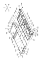
図2には、遊技機10の裏面の構造が示されている。
前面枠12の裏面上部には、払出し前の遊技球を貯留する貯留タンク51と、外部への情報(例えば、図柄確定信号、大当り信号、確率変動信号、賞球信号、貸球信号等)を出力する外部情報端子板41と、が設けられている。また、貯留タンク51の底部には、緩やかな傾斜を有し遊技球を遊技機10の一側へ向けて誘導するシュート52が接続され、シュート52の終端には、遊技球の流下方向を水平方向から垂直方向へと変換する屈曲流路装置53が接続されている。そして、この屈曲流路装置53の下端に駆動源を有する球払出装置54が配設され、この球払出装置54によって所定数の遊技球を払出し可能に構成されている。
FIG. 2 shows the structure of the back surface of the gaming machine 10.
A storage tank 51 for storing game balls before paying out and information to the outside (for example, a symbol confirmation signal, a jackpot signal, a probability variation signal, a winning ball signal, a rental signal, etc.) are provided on the upper rear surface of the front frame 12. An external information terminal board 41 for outputting is provided. In addition, a chute 52 having a gentle inclination and guiding the game ball toward one side of the gaming machine 10 is connected to the bottom of the storage tank 51. A bent channel device 53 that converts the direction to the vertical direction is connected. A ball payout device 54 having a drive source is disposed at the lower end of the bent flow passage device 53, and a predetermined number of game balls can be paid out by the ball payout device 54.
さらに、前面枠12の裏面中央部には、表示装置(画像表示装置)における変動表示ゲームの演出の制御を行う演出制御装置80と、演出制御装置80等の各種装置を統括制御する遊技制御装置100と、等が配設されている。
また、前面枠12の裏面下部には、球払出装置54を制御する払出制御装置60と、遊技機10側とカードユニット側とで授受される信号を中継するカードユニット中継基板70と、遊技制御装置100等の各種制御装置に電源供給を行う電源装置90と、等が設けられている。
Furthermore, in the center of the rear surface of the front frame 12, an effect control device 80 that controls the effect of the variable display game on the display device (image display device), and a game control device that performs overall control of various devices such as the effect control device 80. 100 and the like are arranged.
Further, at the lower back of the front frame 12, a payout control device 60 for controlling the ball payout device 54, a card unit relay board 70 for relaying signals exchanged between the gaming machine 10 side and the card unit side, and game control A power supply device 90 that supplies power to various control devices such as the device 100, and the like are provided.
次に、本実施形態の遊技機10が特徴とする遊技制御装置100(制御装置)について説明する。
遊技制御装置100は、例えば図3、図4に示すように、遊技機10の動作制御等を行うことで遊技の進行を統括的に制御する遊技制御基板110(制御基板)と、当該遊技制御基板110を内部に収納するための基板ボックス120と、を備えて構成される。
そして、遊技制御装置100においては、予め記憶された固有の識別情報を発信可能な電子タグ131を有する電子タグシール130や、当該遊技制御装置100の管理番号等が印字された管理番号シール140、当該遊技制御装置100を備える遊技機10の機種等が印字された機種シール150などが、基板ボックス120(具体的には、基板ボックス120が備える第1ケース部材200(後述)等)に貼着されている。
Next, a game control device 100 (control device) characterized by the gaming machine 10 of the present embodiment will be described.
For example, as shown in FIGS. 3 and 4, the game control device 100 includes a game control board 110 (control board) that performs overall control of the game by performing operation control of the gaming machine 10, and the game control. And a substrate box 120 for accommodating the substrate 110 therein.
In the game control device 100, an electronic tag sticker 130 having an electronic tag 131 capable of transmitting unique identification information stored in advance, a management number sticker 140 on which a management number of the game control device 100 is printed, A model seal 150 or the like on which the model or the like of the gaming machine 10 including the game control device 100 is printed is attached to a substrate box 120 (specifically, a first case member 200 (described later) included in the substrate box 120). ing.
遊技制御装置100は、遊技盤30の背面に取り付けられて当該遊技盤30が前面枠12に取り付けられることによって、例えば図2に示すように、遊技機10の背面側から視認可能に配されている。したがって、以下の説明では、遊技機10の背面側に配された遊技制御装置100を遊技機10の背面側から見た場合(図2参照)に、遊技機10の背面側から視認可能な側を上側、遊技盤30に取り付けられた側を下側とし、上になる側を後側、下になる側を前側とし、左になる側を左側、右になる側を右側とする。
The game control device 100 is attached to the back surface of the game board 30 and the game board 30 is attached to the front frame 12, so that, for example, as shown in FIG. Yes. Therefore, in the following description, when the game control device 100 arranged on the back side of the gaming machine 10 is viewed from the back side of the gaming machine 10 (see FIG. 2), the side that is visible from the back side of the gaming machine 10 Is the upper side, the side attached to the game board 30 is the lower side, the upper side is the rear side, the lower side is the front side, the left side is the left side, and the right side is the right side.
遊技制御基板110は、例えば図4、図14、図15(a),(b)に示すように、その外形が矩形状を呈してなる面実装タイプの基板である。すなわち、遊技制御基板110は、一方向(左右方向)に長尺な基板であり、当該遊技制御基板110の表面110aに、遊技制御用の電子部品111,111,…及びコネクタ(コネクタ端子)116,116,…が面実装されている。
なお、図面では、遊技機10の出荷前における遊技制御装置100の検査時に使用される検査用端子117がコネクタの一種として遊技制御基板110に実装されているが、当該検査用端子117は、遊技機10の出荷時には遊技制御基板110から取り外される。したがって、本実施形態において、コネクタ116は、検査用端子117以外のコネクタを指すものとする。
The game control board 110 is a surface-mounting type board whose outer shape is rectangular as shown in FIGS. 4, 14, 15 (a) and 15 (b), for example. That is, the game control board 110 is a board that is long in one direction (left-right direction), and game control electronic components 111, 111,... And connectors (connector terminals) 116 are provided on the surface 110 a of the game control board 110. 116,... Are surface mounted.
In the drawing, an inspection terminal 117 used when inspecting the game control device 100 before the gaming machine 10 is shipped is mounted on the game control board 110 as a kind of connector. When the machine 10 is shipped, it is removed from the game control board 110. Therefore, in this embodiment, the connector 116 refers to a connector other than the inspection terminal 117.
遊技制御基板110においては、例えば図14に示すように、当該遊技制御基板110の表面110aのうちの後部にコネクタ116が実装されており、当該遊技制御基板110の表面110aのうちの後部以外の部分(前後方向中央部及び前部)に電子部品111が実装されている。
すなわち、遊技制御基板110は、当該遊技制御基板110の長手方向(左右方向)に沿った一方の端部(後端部)側に、他の装置と接続するためのコネクタ116が実装されている。
また、遊技制御基板110は、当該遊技制御基板110の長手方向に沿った他方の端部(前端部)側に、遊技機10の動作に関する電気的制御を実行するための電子部品111が実装されている。
In the game control board 110, for example, as shown in FIG. 14, a connector 116 is mounted on the rear part of the surface 110a of the game control board 110, and other than the rear part of the surface 110a of the game control board 110. The electronic component 111 is mounted on the portion (the central portion in the front-rear direction and the front portion).
That is, the game control board 110 is mounted with a connector 116 for connecting to another device on one end (rear end) side along the longitudinal direction (left-right direction) of the game control board 110. .
In addition, the game control board 110 has an electronic component 111 mounted on the other end (front end) side in the longitudinal direction of the game control board 110 for executing electrical control related to the operation of the gaming machine 10. ing.
電子部品111には、例えば図14に示すように、記憶された遊技プログラムに従って遊技の制御を行う制御デバイス112(遊技用マイクロコンピュータ)と、実装時の高さが当該制御デバイス112よりも低いその他の電子部品111と、が含まれている。
制御デバイス112には、CPU、ROM、RAM等を1チップ化したアミューズチップが内蔵されており、側面に当該制御デバイス112を識別するための識別情報が付されたZIP(Zigzag Inline Package)タイプの電子部品である。そのため、制御デバイス112は、面実装部品であるその他の電子部品111とは異なり、遊技制御基板110に立設されている。したがって、遊技制御基板110に実装されている制御デバイス112は、遊技制御基板110に実装されているその他の電子部品111よりも高さが高く、上方に突出している。
For example, as shown in FIG. 14, the electronic component 111 includes a control device 112 (game microcomputer) that controls a game in accordance with a stored game program, and other components whose mounting height is lower than that of the control device 112. The electronic component 111 is included.
The control device 112 has a built-in amusement chip in which a CPU, ROM, RAM, etc. are integrated into one chip, and is of a ZIP (Zigzag Inline Package) type with identification information for identifying the control device 112 on the side surface. It is an electronic component. Therefore, unlike the other electronic components 111 that are surface-mounted components, the control device 112 is erected on the game control board 110. Therefore, the control device 112 mounted on the game control board 110 is higher than the other electronic components 111 mounted on the game control board 110 and protrudes upward.
また、制御デバイス112は、一方向に長尺な電子部品であり、遊技制御基板110の短手方向(すなわち、第1ケース部材200に対する第2ケース部材300のスライド方向(後述))に沿って、遊技制御基板110に実装されている。そして、制御デバイス112が遊技制御基板110に実装された状態において、当該制御デバイス112の印字面112a(すなわち、当該制御デバイス112を識別するための識別情報等が印字された面)は、遊技制御基板110の短手方向に沿った互いに対向する側方のうちの何れか一方(本実施形態では右側方)を向いている。
The control device 112 is an electronic component that is long in one direction, and is along the short side direction of the game control board 110 (that is, the sliding direction of the second case member 300 with respect to the first case member 200 (described later)). The game control board 110 is mounted. In a state where the control device 112 is mounted on the game control board 110, the print surface 112a of the control device 112 (that is, the surface on which identification information for identifying the control device 112 is printed) It faces either one of the sides facing each other along the short direction of the substrate 110 (right side in this embodiment).
ここで、本実施形態では、制御デバイス112の近傍に、その他の電子部品111を実装しないよう構成されている。
すなわち、遊技制御基板110の表面110aにおいては、制御デバイス112が実装された領域の周囲に、何れの電子部品111も実装されていない非実装領域が設けられている。
そして、例えば図14に示すように、非実装領域のうちの右側(すなわち、制御デバイス112の印字面112a側)の幅(左右方向の長さ)L12は、左側の幅L11よりも大きくなるよう設定されている。
Here, in the present embodiment, the other electronic component 111 is not mounted in the vicinity of the control device 112.
That is, on the surface 110a of the game control board 110, a non-mounting area where no electronic component 111 is mounted is provided around the area where the control device 112 is mounted.
For example, as shown in FIG. 14, the width (length in the left-right direction) L12 on the right side (that is, the printing surface 112a side of the control device 112) in the non-mounting area is larger than the width L11 on the left side. Is set.
コネクタ116には、例えば図14に示すように、遊技者に付与する遊技価値に影響を及ぼす信号(具体的には、遊技の結果に関する信号等)を入出力する端子の他に、遊技制御装置100を電源装置90と接続するための電源用端子118や、遊技機10の出荷後における遊技制御装置100の検査時に使用される外部通信端子119が含まれている。
ここで、本実施形態では、複数のコネクタ116のうちの外部通信端子119が最も上方に突出するよう構成されている。
For example, as shown in FIG. 14, the connector 116 has a game control device in addition to a terminal for inputting / outputting a signal (specifically, a signal related to the result of the game) affecting the game value given to the player. 100 includes a power supply terminal 118 for connecting 100 to the power supply device 90 and an external communication terminal 119 used when the gaming control apparatus 100 is inspected after the gaming machine 10 is shipped.
Here, in the present embodiment, the external communication terminal 119 of the plurality of connectors 116 is configured to protrude most upward.
また、本実施形態では、例えば図14に示すように、遊技制御基板110のうちの、最も左側に実装されたコネクタ116(本実施形態では外部通信端子119)よりも外側の位置と、最も右側に実装されたコネクタ116(本実施形態では電源用端子118)よりも外側の位置と、のそれぞれに、なべネジ170(図18(a)参照)の軸部が上下方向に挿通可能なネジ孔110bが設けられている。
In the present embodiment, for example, as shown in FIG. 14, the position on the outermost side of the connector 116 (external communication terminal 119 in the present embodiment) mounted on the leftmost side of the game control board 110 and the rightmost side. A screw hole through which the shaft portion of the pan screw 170 (see FIG. 18A) can be inserted in the vertical direction at each of the positions outside the connector 116 (the power supply terminal 118 in this embodiment) mounted on 110b is provided.
基板ボックス120は、例えば図3、図4に示すように、遊技制御基板110を収納するための閉止空間Sを画成する第1ケース部材200及び第2ケース部材300と、第1ケース部材200と第2ケース部材300とを合体させて閉止空間Sを画成する閉止状態を保持したまま、第1ケース部材200と第2ケース部材300とを離反不能に結合することが可能な封止手段(左側端封止手段400、右側端封止手段500、挿入端封止手段600)と、電子タグシール130を貼着するための貼着領域R(図22(a)において網掛けされた領域)と、貼着領域Rに貼着された電子タグシール130を保護するための保護カバー部材700と、を備えて構成される。
For example, as shown in FIGS. 3 and 4, the board box 120 includes a first case member 200 and a second case member 300 that define a closed space S for housing the game control board 110, and the first case member 200. The first case member 200 and the second case member 300 can be connected to each other in an inseparable manner while maintaining the closed state in which the closed case S is defined by combining the first case member 300 and the second case member 300. (Left end sealing means 400, right end sealing means 500, insertion end sealing means 600) and a sticking area R for sticking the electronic tag seal 130 (shaded area in FIG. 22A) And a protective cover member 700 for protecting the electronic tag seal 130 attached to the attachment region R.
第1ケース部材200は、例えば図4、図20に示すように、一側部(後側部)に挿入開口200aを有する凹室状の収納空間S*を画成している。
第2ケース部材300は、例えば図4、図20に示すように、遊技制御基板110を収納空間S*内に配置した状態で第1ケース部材200と合体することが可能であるとともに、当該合体した状態で挿入開口200aの縁部と接合して当該挿入開口200aを閉塞することが可能となるよう構成されている。具体的には、第2ケース部材300は、遊技制御基板110を取り付けることが可能となるよう構成されている。また、第2ケース部材300は、収納空間S*を閉止する閉止状態への変換時に挿入開口200aから収納空間S*内へとスライド挿入されて、閉止状態において挿入開口200aの縁部と接合して当該挿入開口200aを閉塞することにより第1ケース部材200とともに閉止空間S(閉止された収納空間S*)を画成することが可能となるよう構成されている。
As shown in FIGS. 4 and 20, for example, the first case member 200 defines a concave chamber-shaped storage space S * having an insertion opening 200a on one side (rear side).
For example, as shown in FIGS. 4 and 20, the second case member 300 can be combined with the first case member 200 in a state where the game control board 110 is disposed in the storage space S * . In this state, the insertion opening 200a can be closed by being joined to the edge of the insertion opening 200a. Specifically, the second case member 300 is configured to allow the game control board 110 to be attached. In addition, the second case member 300 is slid into the storage space S * from the insertion opening 200a during the conversion to the closed state in which the storage space S * is closed, and joined to the edge of the insertion opening 200a in the closed state. By closing the insertion opening 200a, the closed space S (closed storage space S * ) can be defined together with the first case member 200.
すなわち、例えば図20に示すように、第2ケース部材300に遊技制御基板110を取り付けた状態で、第2ケース部材300を、挿入開口200aから第1ケース部材200の内部(収納空間S*内)へと、第1ケース部材200の短手方向(前後方向)に沿って前向きにスライド挿入して、例えば図3に示すように、第1ケース部材200と第2ケース部材300とを合体させると、第1ケース部材200の挿入開口200aが第2ケース部材300(具体的には、第2ケース部材300の開口閉塞部310(後述))で閉塞されて、収納空間S*が閉止された閉止状態(閉止空間Sが画成された状態)となる。
That is, for example, as shown in FIG. 20, with the game control board 110 attached to the second case member 300, the second case member 300 is inserted into the first case member 200 from the insertion opening 200a (inside the storage space S * ), The first case member 200 and the second case member 300 are united as shown in FIG. 3, for example, as shown in FIG. Then, the insertion opening 200a of the first case member 200 is closed by the second case member 300 (specifically, an opening closing portion 310 (described later) of the second case member 300), and the storage space S * is closed. A closed state (a state in which a closed space S is defined) is obtained.
遊技制御基板110は、閉止状態への変換時には、当該遊技制御基板110が取り付けられた第2ケース部材300とともに挿入開口200aから収納空間S*内へとスライド挿入され、閉止状態においては、閉止空間S(閉止された収納空間S*)内に配置されることになる。閉止状態においては、遊技制御基板110が基板ボックス120に完全に内包された状態となるので、当該閉止状態を保持したまま、封止手段(左側端封止手段400、右側端封止手段500、挿入端封止手段600)によって第1ケース部材200と第2ケース部材300とを離反不能に結合すると、大当りの抽選や遊技の進行制御などの遊技に関する種々の処理を実行する遊技制御基板110に対する不正行為等を回避することが可能となる。
また、第1ケース部材200や第2ケース部材300は、例えば透光性の合成樹脂で形成されており、基板ボックス120に内包された遊技制御基板110を遊技制御装置100の外部から視認できるようになっている。
When the game control board 110 is converted to a closed state, the game control board 110 is slid into the storage space S * from the insertion opening 200a together with the second case member 300 to which the game control board 110 is attached. In the closed state, the game control board 110 is closed. It is arranged in S (closed storage space S * ). In the closed state, since the game control board 110 is completely contained in the board box 120, the sealing means (left end sealing means 400, right end sealing means 500, When the first case member 200 and the second case member 300 are unseparably coupled by the insertion end sealing means 600), the game control board 110 that executes various processes relating to the game such as a big win lottery or a game progress control is performed. It is possible to avoid cheating.
The first case member 200 and the second case member 300 are made of, for example, a light-transmitting synthetic resin so that the game control board 110 contained in the board box 120 can be visually recognized from the outside of the game control apparatus 100. It has become.
まず、基板ボックス120が備える第1ケース部材200について説明する。
第1ケース部材200は、例えば図4、図5(a),(b)に示すように、その外形が遊技制御基板110の外形に対応する一方向(左右方向)に長尺な直方体形状を呈してなる部材であり、当該第1ケース部材200の長手方向(左右方向)に沿った互いに対向する側部のうちの何れか一方(後側部)に挿入開口200aが形成されている。
First, the first case member 200 provided in the substrate box 120 will be described.
The first case member 200 has a rectangular parallelepiped shape whose outer shape is long in one direction (left-right direction) corresponding to the outer shape of the game control board 110 as shown in FIGS. 4, 5 (a), (b), for example. The insertion opening 200a is formed in any one (rear side portion) of the side portions facing each other along the longitudinal direction (left-right direction) of the first case member 200.
具体的には、第1ケース部材200は、例えば図5(a),(b)に示すように、遊技制御装置100の下面をなす左右方向に長尺な矩形状の下壁210と、遊技制御装置100の上面の一部(前後方向中央部及び前部)をなす左右方向に長尺な矩形状の上壁220と、遊技制御装置100の左側面の一部(前後方向中央部及び前部)をなし、上壁220の左端部全域から下側に向けて突設されて上壁220の左端部と下壁210の左端部とを連結する左側壁230と、遊技制御装置100の右側面の一部(前後方向中央部及び前部)をなし、上壁220の右端部全域から下側に向けて突設されて上壁220の右端部と下壁210の右端部とを連結する右側壁240と、遊技制御装置100の前側面をなし、上壁220の前端部全域から下側に向けて突設されて上壁220の前端部と下壁210の前端部とを連結する前側壁250と、により構成されている。
Specifically, the first case member 200 includes, for example, a rectangular lower wall 210 that is long in the left-right direction and forms a lower surface of the game control device 100, as shown in FIGS. 5 (a) and 5 (b). A rectangular upper wall 220 that is part of the upper surface of the control device 100 (the central portion and the front portion in the front-rear direction), and a part of the left side surface of the game control device 100 (the central portion and the front portion in the front-rear direction). Left side wall 230 that protrudes downward from the entire left end portion of the upper wall 220 and connects the left end portion of the upper wall 220 and the left end portion of the lower wall 210, and the right side of the game control device 100 It forms a part of the surface (front and rear direction center and front) and projects downward from the entire right end of the upper wall 220 to connect the right end of the upper wall 220 and the right end of the lower wall 210. The right side wall 240 and the front side of the game control device 100 are formed, and the lower side from the entire front end portion of the upper wall 220 A side wall 250 before connecting the front end portion of the front end portion and the lower wall 210 of the top wall 220 is projected toward, and is composed of.
ここで、下壁210の短手方向(前後方向)の長さは、遊技制御基板110の短手方向の長さよりも若干長くなるよう設定されているとともに、下壁210の長手方向(左右方向)の長さは、遊技制御基板110の長手方向の長さよりも若干長くなるよう設定されている。
また、上壁220の長手方向(左右方向)の長さは、下壁210(具体的には、下壁210の前後方向中央部及び前部)の長手方向の長さと同一となるよう設定されており、上壁220の短手方向(前後方向)の長さは、下壁210の短手方向の長さよりも短くなるよう設定されている。
また、左側壁230及び右側壁240の前後方向の長さは、上壁220の短手方向の長さと同一となるよう設定されている。
すなわち、挿入開口200aは、第1ケース部材200の側部(具体的には、左側部の一部(後部)、後側部及び右側部の一部(後部))から第1ケース部材200の上部の一部(後部)にかけて開口している。
Here, the length of the lower wall 210 in the short direction (front-back direction) is set to be slightly longer than the length of the game control board 110 in the short direction, and the length of the lower wall 210 (left-right direction) ) Is set to be slightly longer than the length of the game control board 110 in the longitudinal direction.
Further, the length of the upper wall 220 in the longitudinal direction (left-right direction) is set to be the same as the length of the lower wall 210 (specifically, the central portion and the front portion of the lower wall 210 in the front-rear direction). The length of the upper wall 220 in the short direction (front-rear direction) is set to be shorter than the length of the lower wall 210 in the short direction.
The lengths of the left and right walls 230 and 240 in the front-rear direction are set to be the same as the length of the upper wall 220 in the short direction.
In other words, the insertion opening 200a extends from the side of the first case member 200 (specifically, a part of the left side (rear part), a part of the rear side and a part of the right side (rear part)). It opens to a part of the upper part (rear part).
また、上壁220の長手方向の長さは、下壁210(具体的には、下壁210の前後方向中央部及び前部)の長手方向の長さと同一であるとともに、上壁220の短手方向の長さは、下壁210の短手方向の長さよりも短いので、閉止空間Sに遊技制御基板110を収納した状態(収納空間S*内に遊技制御基板110を配置した状態)において、下壁210は、当該遊技制御基板110の裏面(下面)全体を被覆可能であるのに対し、上壁220は、当該遊技制御基板110の表面110a(上面)のうちの前後方向中央部及び前部(すなわち、電子部品111,111,…が実装された部分)のみを被覆して、当該遊技制御基板110の表面110aのうちの後部(すなわち、コネクタ116,116,…が実装された部分)は被覆しないよう構成されている。すなわち、閉止空間Sに遊技制御基板110を収納した状態において、当該遊技制御基板110の前後方向中央部及び前部は収納空間S*内に配置され、当該遊技制御基板110の後部は収納空間S*内に配置されないよう構成されている。
The length in the longitudinal direction of the upper wall 220 is the same as the length in the longitudinal direction of the lower wall 210 (specifically, the central portion and the front portion in the front-rear direction of the lower wall 210) and the short length of the upper wall 220. Since the length in the hand direction is shorter than the length in the short direction of the lower wall 210, the game control board 110 is stored in the closed space S (the game control board 110 is placed in the storage space S * ). The lower wall 210 can cover the entire back surface (lower surface) of the game control board 110, whereas the upper wall 220 is a front-rear central portion of the surface 110a (upper surface) of the game control board 110 and Only the front portion (that is, the portion on which the electronic components 111, 111,... Are mounted) is covered, and the rear portion (that is, the portion on which the connectors 116, 116,... Are mounted) on the surface 110a of the game control board 110. ) Is not covered Configured. That is, in a state where the game control board 110 is stored in the closed space S, the center and front part in the front-rear direction of the game control board 110 are arranged in the storage space S * , and the rear part of the game control board 110 is stored in the storage space S. * It is configured not to be placed inside.
また、下壁210は、例えば図5(a),(b)に示すように、当該下壁210の後部(すなわち、当該下壁210のうちの上壁220と対向しない部分)の長手方向の長さが、当該下壁210の後部以外の部分(すなわち、当該下壁210の前後方向中央部及び前部であり、当該下壁210のうちの上壁220と対向する部分)の長手方向の長さよりも短くなるよう形成されている。
Further, the lower wall 210 is, for example, in the longitudinal direction of the rear portion of the lower wall 210 (that is, the portion of the lower wall 210 not facing the upper wall 220) as shown in FIGS. The length of the portion other than the rear portion of the lower wall 210 (that is, the central portion and the front portion in the front-rear direction of the lower wall 210 and the portion facing the upper wall 220 of the lower wall 210) It is formed to be shorter than the length.
また、下壁210には、例えば図5(b)に示すように、第1ケース部材200(特に下壁210)を補強するための補強リブ211が設けられている。
なお、本実施形態では、補強リブ211を、下壁210の下面のうちの左端部分全域に設けられたリブと、下壁210の下面のうちの右端部分全域に設けられたリブと、下壁210の下面のうちの後端部分左側に設けられて左端部分全域のリブと連結するリブと、下壁210の下面のうちの後端部分右側に設けられて右端部分全域のリブと連結するリブと、下壁210の下面のうちの前端部分中央部に設けられたリブと、後端部分左側のリブと前端部分中央部のリブとを連結するリブと、後端部分右側のリブと前端部分中央部のリブとを連結するリブと、により構成したが、これに限ることはなく、補強リブ211によって第1ケース部材200(特に下壁210)を補強できるのであれば、補強リブ211の構成は任意である。
In addition, the lower wall 210 is provided with reinforcing ribs 211 for reinforcing the first case member 200 (particularly the lower wall 210) as shown in FIG. 5B, for example.
In the present embodiment, the reinforcing ribs 211 are provided in the entire left end portion of the lower surface of the lower wall 210, the rib provided in the entire right end portion of the lower surface of the lower wall 210, and the lower wall. A rib provided on the left side of the rear end portion of the lower surface of 210 and connected to the ribs in the entire left end portion, and a rib provided on the right side of the rear end portion of the lower surface of lower wall 210 and connected to the ribs in the entire right end portion A rib provided at the center of the front end portion of the lower surface of the lower wall 210, a rib connecting the rib on the left side of the rear end portion and the rib on the center portion of the front end portion, the rib on the right side of the rear end portion, and the front end portion However, the present invention is not limited to this, and if the first case member 200 (particularly the lower wall 210) can be reinforced by the reinforcing rib 211, the reinforcing rib 211 is configured. Is optional.
上壁220は、例えば図5(a)、図7(a)に示すように、閉止状態において第2ケース部材300の囲繞カバー本体部331(後述)に対応する位置に、当該上壁220の挿入開口200a側の端部(後端部)から前端部までに亘って、収納空間S*の奥行き方向(前後方向)に沿って設けられた露出用切欠部221を有している。
また、上壁220は、例えば図5(a)、図7(a)に示すように、当該上壁220のうちの露出用切欠部221の左右の縁部に収納空間S*の奥行き方向(前後方向)に延設されたスライドガイド溝部222を有している。具体的には、スライドガイド溝部222は、上壁220のうちの露出用切欠部221を挟む左右両側の所定幅の領域それぞれが折曲されて、下方及び後方に開口するよう形成されており、閉止状態への変換時及び閉止状態時に第2ケース部材300のスライドガイド壁332a(後述)と係合可能となっている。そして、上壁220には、例えば図7(a),(b)に示すように、右側のスライドガイド溝部222の形成に伴って上壁220の外面(上面)に形成された左右の角部のうちの左側の角部が面取りされて面取り部222aが形成されている。
For example, as shown in FIGS. 5A and 7A, the upper wall 220 is located at a position corresponding to the surrounding cover main body 331 (described later) of the second case member 300 in the closed state. An exposure notch 221 is provided along the depth direction (front-rear direction) of the storage space S * from the end (rear end) on the insertion opening 200a side to the front end.
Further, as shown in FIGS. 5A and 7A, for example, the upper wall 220 is formed in the depth direction of the storage space S * at the left and right edges of the exposure notch 221 in the upper wall 220 (see FIG. It has a slide guide groove 222 extending in the front-rear direction). Specifically, the slide guide groove portion 222 is formed such that each region of a predetermined width on both the left and right sides of the upper wall 220 sandwiching the notch 221 for exposure is bent and opened downward and rearward. It can be engaged with a slide guide wall 332a (described later) of the second case member 300 at the time of conversion to the closed state and at the closed state. The upper wall 220 has left and right corners formed on the outer surface (upper surface) of the upper wall 220 with the formation of the right slide guide groove 222, for example, as shown in FIGS. The left corner is chamfered to form a chamfered portion 222a.
また、上壁220には、例えば図5(a)、図7(a)に示すように、露出用切欠部221のうちの挿入開口200a側とは反対側の部分を閉塞する侵入防止壁223が設けられている。
また、右側壁240には、例えば図5(a)に示すように、当該右側壁240の上端部のうちの後端から前後方向中央よりも前側の所定位置までに亘って、右側端封止手段500に取り付けられた保護カバー部材700の位置ズレを規制するためのストッパー241が設けられている。
また、挿入開口200aに対向する前側壁250(奥側壁)は、例えば図6(a),(b)、図7(b)に示すように、左右方向中央よりも左側の所定位置と右側の所定位置とのそれぞれに、前第2固着部620(後述)を挿通可能な挿通口251を有している。
Further, for example, as shown in FIGS. 5A and 7A, the upper wall 220 has an intrusion prevention wall 223 that closes a portion of the exposure notch 221 opposite to the insertion opening 200a. Is provided.
Further, as shown in FIG. 5A, for example, the right side wall 240 is sealed on the right side from the rear end of the upper side of the right side wall 240 to a predetermined position in front of the center in the front-rear direction. A stopper 241 for restricting the displacement of the protective cover member 700 attached to the means 500 is provided.
Further, the front side wall 250 (back side wall) facing the insertion opening 200a has a predetermined position on the left side of the center in the left-right direction and the right side as shown in FIGS. 6A, 6B, and 7B, for example. Each of the predetermined positions has an insertion port 251 through which the front second fixing portion 620 (described later) can be inserted.
次に、基板ボックス120が備える第2ケース部材300について説明する。
第2ケース部材300は、例えば図4、図8(a),(b)に示すように、遊技制御基板110を下方から取り付けることが可能であるとともに、当該第2ケース部材300に取り付けられた遊技制御基板110の外周を囲繞することが可能な枠状を呈してなる部材である。
Next, the second case member 300 provided in the substrate box 120 will be described.
For example, as shown in FIGS. 4, 8 </ b> A, and 8 </ b> B, the second case member 300 can be attached to the game control board 110 from below and is attached to the second case member 300. This is a member having a frame shape that can surround the outer periphery of the game control board 110.
具体的には、第2ケース部材300は、第1ケース部材200と合体した状態で挿入開口200aの縁部と接合して当該挿入開口200aを閉塞することが可能な開口閉塞部310と、当該第2ケース部材300に取り付けられた遊技制御基板110を支持することが可能な基板支持部(挿入部)320と、当該第2ケース部材300に取り付けられた遊技制御基板110に実装されている制御デバイス112の周囲を囲繞することが可能な囲繞カバー部330と、を備えて構成される。
そして、第2ケース部材300においては、例えば図25に示すように、開口閉塞部310(具体的には、開口閉塞部310の側方閉塞部316(後述))と、基板支持部(挿入部)320と、によって当該第2ケース部材300に取り付けられた遊技制御基板110の外周を囲繞するよう構成されている。
Specifically, the second case member 300 is joined to the edge of the insertion opening 200a in a state of being combined with the first case member 200, and the opening closing portion 310 that can close the insertion opening 200a; A board support part (insertion part) 320 capable of supporting the game control board 110 attached to the second case member 300 and a control mounted on the game control board 110 attached to the second case member 300. And a surrounding cover portion 330 that can surround the periphery of the device 112.
In the second case member 300, as shown in FIG. 25, for example, an opening blocking portion 310 (specifically, a side blocking portion 316 (described later) of the opening blocking portion 310) and a substrate support portion (insertion portion). ) 320 to surround the outer periphery of the game control board 110 attached to the second case member 300.
ここで、本実施形態において挿入開口200aの縁部とは、第1ケース部材200において、下壁210の後端部と、下壁210の左端部のうちの後部と、左側壁230の後端部と、上壁220の後端部と、右側壁240の後端部と、下壁210の右端部のうちの後部と、よりなる一続きの部分である。そして、閉止状態において、第1ケース部材200における当該一続きの部分と、第2ケース部材300と、の重合境界が、第1ケース部材200と第2ケース部材300との接合部分になる。
Here, in this embodiment, the edge of the insertion opening 200a refers to the rear end of the lower wall 210, the rear of the left end of the lower wall 210, and the rear end of the left side wall 230 in the first case member 200. And a rear end portion of the upper wall 220, a rear end portion of the right side wall 240, and a rear portion of the right end portion of the lower wall 210. In the closed state, the overlapping boundary between the continuous portion of the first case member 200 and the second case member 300 becomes a joint portion between the first case member 200 and the second case member 300.
第2ケース部材300の左右方向の長さは、収納空間S*の左右方向の長さと略同一となるよう設定されている。
また、第2ケース部材300の前後方向中央部及び前部をなす基板支持部(挿入部)320の前後方向の長さは、収納空間S*の前後方向の長さと略同一となるよう設定されているとともに、基板支持部(挿入部)320の上下方向の長さは、収納空間S*の上下方向の長さと略同一となるよう設定されている。すなわち、第2ケース部材300のうちの基板支持部(挿入部)320のみが、閉止状態において収納空間S*内に配置されるよう構成されている。
また、第2ケース部材300の後部をなす開口閉塞部310の前後方向の長さは、下壁210の後部の前後方向の長さよりも若干長くなるよう設定されている。具体的には、閉止状態において、開口閉塞部310(具体的には、開口閉塞部310の当接部311a(後述))が、第1ケース部材200を構成する上壁220の後端部に対して後側から当接するとともに、開口閉塞部310(具体的には、開口閉塞部310の側方閉塞部316(後述)を構成する後側壁部)が、第1ケース部材200を構成する下壁210の後端部に対して後側から当接するよう構成されている。
The length of the second case member 300 in the left-right direction is set to be substantially the same as the length of the storage space S * in the left-right direction.
Further, the length in the front-rear direction of the substrate support part (insertion part) 320 that forms the center part and the front part in the front-rear direction of the second case member 300 is set to be substantially the same as the length in the front-rear direction of the storage space S *. In addition, the vertical length of the substrate support portion (insertion portion) 320 is set to be substantially the same as the vertical length of the storage space S * . That is, only the substrate support part (insertion part) 320 of the second case member 300 is configured to be disposed in the storage space S * in the closed state.
Further, the length in the front-rear direction of the opening blocking portion 310 that forms the rear portion of the second case member 300 is set to be slightly longer than the length in the front-rear direction of the rear portion of the lower wall 210. Specifically, in the closed state, the opening blocking portion 310 (specifically, the contact portion 311a (described later) of the opening blocking portion 310) is formed at the rear end portion of the upper wall 220 constituting the first case member 200. The opening closing part 310 (specifically, the rear side wall part constituting the side closing part 316 (described later) of the opening closing part 310) is in contact with the rear side of the lower case part of the first case member 200. It is comprised so that it may contact | abut from the rear side with respect to the rear-end part of the wall 210. FIG.
開口閉塞部310は、例えば図8(a),(b)に示すように、挿入開口200aを第1ケース部材200の上部の一部側(後部側)から閉塞することが可能な上方閉塞部311と、遊技制御装置100の左側面の一部(後部)と後面と右側面の一部(後部)とをなし、挿入開口200aを第1ケース部材200の側部側(具体的には、左側部の一部(後部)側、後側部側及び右側部の一部(後部)側)から閉塞することが可能な側方閉塞部316と、により構成されている。
ここで、遊技制御基板110は、例えば図4に示すように、当該遊技制御基板110に実装されているコネクタ116が開口閉塞部310側に位置し、かつ、当該遊技制御基板110の表面110aが当該開口閉塞部310(具体的には、当該開口閉塞部310の下面)に対向するよう第2ケース部材300に取り付けられる。すなわち、開口閉塞部310は、第2ケース部材300に遊技制御基板110を取り付けた状態において、当該開口閉塞部310の下面が、当該遊技制御基板110の表面110aのうちの後部に対向するよう構成されている。
For example, as shown in FIGS. 8A and 8B, the opening blocking portion 310 is an upper blocking portion that can block the insertion opening 200 a from a part of the upper side of the first case member 200 (rear side). 311, part of the left side (rear part) of the game control device 100, rear part and part of the right side (rear part), and the insertion opening 200 a on the side part side of the first case member 200 (specifically, It is comprised by the side obstruction | occlusion part 316 which can be obstruct | occluded from a part (rear part) side of the left side part, a rear side part side, and a part (rear part) side of the right side part.
Here, in the game control board 110, for example, as shown in FIG. 4, the connector 116 mounted on the game control board 110 is located on the opening closing portion 310 side, and the surface 110a of the game control board 110 is It is attached to the second case member 300 so as to face the opening blocking portion 310 (specifically, the lower surface of the opening blocking portion 310). That is, the opening closing portion 310 is configured such that the lower surface of the opening closing portion 310 faces the rear portion of the surface 110a of the game control substrate 110 in a state where the game control board 110 is attached to the second case member 300. Has been.
上方閉塞部311は、例えば図8(a),(b)に示すように、左右方向に長尺な矩形状を呈してなり、第2ケース部材300に取り付けられた遊技制御基板110に実装されているコネクタ116,116,…に対応する位置に、閉止状態において当該コネクタ116,116,…を基板ボックス120の外部に露出させるためのコネクタ用開口312,312,…を有している。
また、上方閉塞部311は、例えば図8(b)に示すように、当該上方閉塞部311の下面のうちのコネクタ用開口312の縁部の周囲に、端子カバー部材160(後述)を囲繞するための端子カバー囲繞壁313を有している。
For example, as shown in FIGS. 8A and 8B, the upper blocking portion 311 has a rectangular shape that is long in the left-right direction, and is mounted on the game control board 110 attached to the second case member 300. Are provided with connector openings 312, 312,... For exposing the connectors 116, 116,... To the outside of the board box 120 in the closed state.
Further, for example, as shown in FIG. 8B, the upper closing portion 311 surrounds a terminal cover member 160 (described later) around the edge of the connector opening 312 on the lower surface of the upper closing portion 311. The terminal cover surrounding wall 313 is provided.
ここで、本実施形態では、基板ボックス120は、例えば図17(a)に示すように、コネクタ116の脚部(端子部)116a,116a,…を保護することが可能な端子カバー部材160を備えており、例えば図17(b)、図18(a),(b)に示すように、コネクタ116に端子カバー部材160を装着した状態で、遊技制御基板110を第2ケース部材300に取り付けるよう構成されている。
これにより、脚部116aの破損や脚部116aへの不正アクセスなどを回避することが可能となる。すなわち、本実施形態では、コネクタ116,116,…が遊技制御基板110に面実装されているので、例えば図17(a)に示すように、コネクタ116の脚部116a,116a,…は、当該コネクタ116本体部の下端部から側方に突設されており、遊技制御基板110の表面110aから突出している。そのため、このままでは、脚部116aの破損や脚部116aへの不正アクセスなどの不都合が発生し易いが、本実施形態では、独立した各端子カバー部材160により脚部116a,116a,…を保護しているので、当該不都合を回避することができる。
In this embodiment, the board box 120 includes a terminal cover member 160 capable of protecting the leg portions (terminal portions) 116a, 116a,... Of the connector 116, as shown in FIG. For example, as shown in FIGS. 17B, 18A, and 18B, the game control board 110 is attached to the second case member 300 in a state where the terminal cover member 160 is attached to the connector 116. It is configured as follows.
As a result, it is possible to avoid damage to the leg portion 116a and unauthorized access to the leg portion 116a. That is, in this embodiment, since the connectors 116, 116,... Are surface-mounted on the game control board 110, for example, as shown in FIG. 17 (a), the legs 116a, 116a,. The connector 116 protrudes laterally from the lower end of the main body and protrudes from the surface 110 a of the game control board 110. Therefore, in this state, inconveniences such as breakage of the leg portion 116a and unauthorized access to the leg portion 116a are likely to occur. However, in this embodiment, the leg portions 116a, 116a,. Therefore, the inconvenience can be avoided.
なお、本実施形態では、例えば図14、図18(a)に示すように、遊技者に付与する遊技価値に影響を及ぼす信号を入出力するコネクタ116(具体的には、電源用端子118や外部通信端子119以外のコネクタ116)の脚部116aのみが表面110aから突出しており、脚部116aが表面110aから突出しているコネクタ116に端子カバー部材160を装着するよう構成したが、これに限ることはなく、例えば、脚部116aが表面110aから突出しているコネクタ116のうちの特定のコネクタ116のみに端子カバー部材160を装着するよう構成しても良いし、脚部116aが表面110aから突出しているか否かにかかわらず全てのコネクタ116に端子カバー部材160を装着するよう構成しても良い。
In the present embodiment, as shown in FIGS. 14 and 18A, for example, a connector 116 (specifically, a power supply terminal 118 or a terminal for inputting / outputting a signal that affects the game value given to the player). Only the leg portion 116a of the connector 116) other than the external communication terminal 119 protrudes from the surface 110a, and the terminal cover member 160 is attached to the connector 116 from which the leg portion 116a protrudes from the surface 110a. For example, the terminal cover member 160 may be mounted only on a specific connector 116 out of the connectors 116 whose legs 116a protrude from the surface 110a, or the legs 116a protrude from the surface 110a. The terminal cover members 160 may be attached to all the connectors 116 regardless of whether or not they are provided.
端子カバー部材160は、例えば図16(a),(b)に示すように、第2ケース部材300の開口閉塞部310と遊技制御基板110との間に挟持されてコネクタ116の脚部116a,116a,…を保護するための端子カバー本体部161と、端子カバー本体部161の上面に立設された起立壁部162と、により構成されている。
For example, as shown in FIGS. 16A and 16B, the terminal cover member 160 is sandwiched between the opening closing portion 310 of the second case member 300 and the game control board 110, and the leg portions 116a, 116a,... Are configured by a terminal cover main body part 161 for protecting the terminal cover main body part 161, and a standing wall part 162 standing on the upper surface of the terminal cover main body part 161.
端子カバー本体部161は、その外形が直方体形状を呈してなり、その内部に下部に開口を有する凹室状の空間が形成されている。また、端子カバー本体部161は、当該端子カバー本体部161を構成する上壁部に、対応するコネクタ116(コネクタ116本体部)の上面視外形と同一形状のコネクタ挿入口を有している。そして、端子カバー本体部161は、例えば図24(a),(b)に示すように、端子カバー部材160をコネクタ116に装着した状態(すなわち、端子カバー本体部161の下端部が遊技制御基板110の表面110aに接した状態)において、コネクタ116の脚部116aに接することなく、端子カバー本体部161の内部(凹室状の空間内)に、当該コネクタ116の脚部116a,116a,…を収納可能となるよう構成されている。
The terminal cover main body 161 has a rectangular parallelepiped outer shape, and a concave chamber-like space having an opening in the lower portion is formed therein. Further, the terminal cover main body portion 161 has a connector insertion port having the same shape as the top view outer shape of the corresponding connector 116 (connector 116 main body portion) on the upper wall portion constituting the terminal cover main body portion 161. The terminal cover main body 161 is in a state where the terminal cover member 160 is attached to the connector 116 as shown in FIGS. 24A and 24B, for example (the lower end of the terminal cover main body 161 is the game control board. 110 in a state of being in contact with the front surface 110a of the connector 110), without contacting the leg portion 116a of the connector 116, the leg portions 116a, 116a,. It is comprised so that storage is possible.
起立壁部162は、端子カバー本体部161を構成する上壁部の上面のうちのコネクタ挿入口の縁部から上側に向けて突設されている。
ここで、本実施形態では、例えば図19(a)、図24(a),(b)に示すように、基板に対するコネクタ116の取り付けガタ等に対応できるよう、コネクタ用開口312のサイズが、対応するコネクタ116(コネクタ116本体部)の上面視外形よりも大きく設定されており、コネクタ用開口312の端面と、コネクタ116本体部の外側面と、の間には隙間が生じている。また、端子カバー本体部161のコネクタ挿入口の形状は対応するコネクタ116(コネクタ116本体部)の上面視外形と同一であり、起立壁部162は当該コネクタ挿入口の縁部から突設されているので、端子カバー部材160をコネクタ116に装着した状態において、起立壁部162は、コネクタ用開口312の端面と、当該コネクタ116本体部の外側面と、の間に生じている隙間に配置された状態で、当該起立壁部162の内面が当該コネクタ116本体部の外側面と当接している。
このように、起立壁部162を設けることにより、コネクタ116に端子カバー部材160を的確に取り付けることが可能となる。
また、端子カバー本体部161が有するコネクタ挿入口は、対応するコネクタ116(コネクタ116本体部)の上面視外形と同一形状であり、端子カバー部材160をコネクタ116に装着した状態において、当該コネクタ挿入口の端面と、当該コネクタ116本体部の外側面と、は当接している。そのため、当該コネクタ挿入口から針金やピアノ線などを挿入することは困難であるが、さらに本実施形態では、起立壁部162を設けることによって、当該コネクタ挿入口からの針金やピアノ線などの挿入を一層困難にしているので、脚部116aへの不正アクセス等を十分に回避することが可能となる。
The standing wall 162 projects upward from the edge of the connector insertion slot on the upper surface of the upper wall constituting the terminal cover main body 161.
Here, in this embodiment, for example, as shown in FIG. 19A, FIG. 24A, and FIG. The outer shape of the corresponding connector 116 (connector 116 main body) is set to be larger than the top view, and a gap is generated between the end surface of the connector opening 312 and the outer surface of the connector 116 main body. Further, the shape of the connector insertion port of the terminal cover main body 161 is the same as the top view of the corresponding connector 116 (connector 116 main body), and the upright wall 162 projects from the edge of the connector insertion port. Therefore, in a state where the terminal cover member 160 is attached to the connector 116, the standing wall 162 is disposed in a gap generated between the end surface of the connector opening 312 and the outer surface of the connector 116 main body. In this state, the inner surface of the standing wall 162 is in contact with the outer surface of the connector 116 main body.
As described above, by providing the standing wall 162, the terminal cover member 160 can be accurately attached to the connector 116.
Further, the connector insertion opening of the terminal cover main body 161 has the same shape as the top view of the corresponding connector 116 (connector 116 main body), and when the terminal cover member 160 is attached to the connector 116, the connector insertion port The end face of the mouth is in contact with the outer surface of the main body of the connector 116. Therefore, although it is difficult to insert a wire, a piano wire, or the like from the connector insertion port, in the present embodiment, by providing a standing wall 162, insertion of a wire, a piano wire, or the like from the connector insertion port is possible. Therefore, unauthorized access to the leg portion 116a can be sufficiently avoided.
また、起立壁部162には、例えば図16(a),(b)に示すように、当該起立壁部162の上端部のうちの外側の角部が面取りされてテーパ部162aが形成されている。
すなわち、起立壁部162の上端部には、外側に向けて下り傾斜するテーパ部162aが設けられているので、端子カバー部材160が装着されたコネクタ116を、コネクタ用開口312の下方から挿入し易くなり、第2ケース部材300に遊技制御基板110を取り付ける際の作業性が向上する。
Further, as shown in FIGS. 16A and 16B, for example, the outer corner of the upper end of the standing wall 162 is chamfered on the standing wall 162 to form a tapered portion 162a. Yes.
In other words, the upper end portion of the standing wall portion 162 is provided with a tapered portion 162a that is inclined downward toward the outside, so that the connector 116 to which the terminal cover member 160 is attached is inserted from below the connector opening 312. It becomes easy and workability | operativity at the time of attaching the game control board 110 to the 2nd case member 300 improves.
端子カバー囲繞壁313は、例えば図19(a)、図24(a),(b)に示すように、第2ケース部材300に遊技制御基板110を取り付けた状態において、当該端子カバー囲繞壁313の先端部(下端部)が当該遊技制御基板110の表面110aと当接し、かつ、上方閉塞部311の下面(具体的には、上方閉塞部311の下面のうちのコネクタ用開口312の縁部)が端子カバー部材160の端子カバー本体部161の上面と当接するよう、上方閉塞部311の下面のうちのコネクタ用開口312の縁部の周囲から下側に向けて突設されている。
これにより、遊技制御基板110への不正アクセス等を回避することが可能となる。すなわち、本実施形態では、基板に対するコネクタ116の取り付けガタ等に対応できるよう、コネクタ用開口312のサイズが、対応するコネクタ116に装着される端子カバー部材160の起立壁部162の上面視外形よりも若干大きく設定されており、コネクタ用開口312の端面と、起立壁部162の外側面と、の間に隙間が生じているので、当該隙間から針金やピアノ線などが挿入される虞れがある。本実施形態では、上方閉塞部311の下面と端子カバー本体部161の上面とが当接しているので、当該隙間から挿入された針金やピアノ線などが基板ボックス120の内部(閉止空間S内)へと侵入することは困難であるが、さらに本実施形態では、先端部が遊技制御基板110の表面110aと当接する端子カバー囲繞壁313でコネクタ用開口312の周囲を囲むことによって、当該侵入を一層困難にしているので、遊技制御基板110への不正アクセス等を十分に回避することが可能となる。
For example, as shown in FIG. 19A, FIG. 24A, and FIG. 24B, the terminal cover surrounding wall 313 is the terminal cover surrounding wall 313 when the game control board 110 is attached to the second case member 300. And the lower end of the upper closing part 311 (specifically, the edge part of the connector opening 312 in the lower face of the upper closing part 311). ) Protrudes from the periphery of the edge of the connector opening 312 on the lower surface of the upper closing portion 311 toward the lower side so as to contact the upper surface of the terminal cover main body 161 of the terminal cover member 160.
As a result, unauthorized access to the game control board 110 can be avoided. That is, in the present embodiment, the size of the connector opening 312 is larger than that of the standing wall portion 162 of the terminal cover member 160 attached to the corresponding connector 116 so as to cope with the mounting looseness of the connector 116 with respect to the board. Is set to be slightly larger, and a gap is formed between the end surface of the connector opening 312 and the outer surface of the upright wall portion 162. Therefore, there is a possibility that a wire, a piano wire, or the like is inserted from the gap. is there. In the present embodiment, since the lower surface of the upper closing portion 311 and the upper surface of the terminal cover main body portion 161 are in contact with each other, the wire inserted from the gap, the piano wire, or the like is inside the substrate box 120 (in the closed space S). However, in this embodiment, the intrusion is prevented by surrounding the connector opening 312 with a terminal cover surrounding wall 313 whose tip is in contact with the surface 110a of the game control board 110. Since it is made more difficult, unauthorized access to the game control board 110 can be sufficiently avoided.
また、端子カバー囲繞壁313は、第2ケース部材300に遊技制御基板110を取り付けた状態において、当該端子カバー囲繞壁313の内側面が、端子カバー部材160の端子カバー本体部161の外側面と当接しない位置に設けられている。
これにより、基板に対するコネクタ116の取り付けガタ等に十分に対応することが可能となる。すなわち、第2ケース部材300に遊技制御基板110を取り付けた状態において、端子カバー囲繞壁313の内側面と、端子カバー本体部161の外側面と、が当接するように端子カバー囲繞壁313が設けられている場合、遊技制御基板110を第2ケース部材300に取り付ける際に、取り付けガタ等の影響で、端子カバー部材160が装着されたコネクタ116をコネクタ用開口312に的確に挿入できない等の虞れがある。これに対し、本実施形態では、第2ケース部材300に遊技制御基板110を取り付けた状態において、端子カバー囲繞壁313の内側面と、端子カバー本体部161の外側面と、が当接しないように端子カバー囲繞壁313を設けているので、取り付けガタ等が生じていても、遊技制御基板110を第2ケース部材300に取り付ける際に、端子カバー部材160が装着されたコネクタ116をコネクタ用開口312に的確に挿入することができることとなって、当該取り付けガタ等に十分に対応することが可能となる。
In addition, the terminal cover surrounding wall 313 is configured so that the inner side surface of the terminal cover surrounding wall 313 is in contact with the outer side surface of the terminal cover main body portion 161 of the terminal cover member 160 when the game control board 110 is attached to the second case member 300. It is provided at a position where it does not contact.
As a result, it is possible to sufficiently cope with the mounting looseness of the connector 116 with respect to the substrate. That is, the terminal cover surrounding wall 313 is provided so that the inner side surface of the terminal cover surrounding wall 313 and the outer side surface of the terminal cover main body portion 161 come into contact with each other when the game control board 110 is attached to the second case member 300. If the game control board 110 is attached to the second case member 300, the connector 116 to which the terminal cover member 160 is attached may not be accurately inserted into the connector opening 312 due to the influence of attachment play or the like. There is. On the other hand, in the present embodiment, in a state where the game control board 110 is attached to the second case member 300, the inner side surface of the terminal cover surrounding wall 313 and the outer side surface of the terminal cover main body portion 161 do not come into contact with each other. Since the terminal cover surrounding wall 313 is provided, the connector 116 to which the terminal cover member 160 is attached can be opened when the game control board 110 is attached to the second case member 300 even if mounting play or the like occurs. Since it can be inserted into 312 accurately, it is possible to sufficiently cope with the mounting play.
なお、本実施形態では、例えば図8(b)、図11(a),(b),(c)、図19(a)に示すように、隣接するコネクタ用開口312同士の間隔が所定の閾値以下であり、かつ、当該コネクタ用開口312同士の前後方向の長さが略同一であれば、端子カバー囲繞壁313で当該コネクタ用開口312同士を一緒に囲むことによって端子カバー囲繞壁313がシンプルなものとなるよう構成したが、これに限ることはなく、例えば、各コネクタ用開口312を端子カバー囲繞壁313で一つずつ囲むよう構成しても良いし、コネクタ用開口312同士の間隔や前後方向の長さにかかわらず複数のコネクタ用開口312を端子カバー囲繞壁313で一緒に囲むことによって端子カバー囲繞壁313が一層シンプルなものとなるよう構成しても良い。
In this embodiment, for example, as shown in FIG. 8B, FIG. 11A, FIG. 11B, FIG. 19C, and FIG. If the lengths in the front-rear direction of the connector openings 312 are substantially the same as the threshold value or less, the terminal cover surrounding wall 313 is surrounded by the terminal cover surrounding walls 313 together. However, the present invention is not limited to this. For example, each connector opening 312 may be surrounded by the terminal cover surrounding wall 313 one by one, or the distance between the connector openings 312 may be The terminal cover surrounding wall 313 is configured to be simpler by surrounding the connector openings 312 together with the terminal cover surrounding wall 313 regardless of the length in the front-rear direction. Good.
また、本実施形態では、端子カバー部材160が装着されるコネクタ116(図4参照)に対応するコネクタ用開口312の周囲のみに端子カバー囲繞壁313を設けるよう構成したが、これに限ることはなく、例えば、端子カバー部材160が装着されるコネクタ116に対応するコネクタ用開口312のうちの特定のコネクタ用開口312の周囲のみに端子カバー囲繞壁313を設けるよう構成しても良いし、端子カバー部材160が装着されるコネクタ116に対応するか否かにかかわらず全てのコネクタ用開口312の周囲に端子カバー囲繞壁313を設けるよう構成しても良い。
In the present embodiment, the terminal cover surrounding wall 313 is provided only around the connector opening 312 corresponding to the connector 116 (see FIG. 4) to which the terminal cover member 160 is attached. However, the present invention is not limited to this. For example, the terminal cover surrounding wall 313 may be provided only around the specific connector opening 312 of the connector openings 312 corresponding to the connector 116 to which the terminal cover member 160 is mounted, The terminal cover surrounding wall 313 may be provided around all the connector openings 312 regardless of whether the cover member 160 corresponds to the connector 116 to which the cover member 160 is attached.
また、上方閉塞部311は、例えば図8(a),(b)、図18(a),(b)に示すように、閉止状態において第1ケース部材200の上壁220のうちの挿入開口200a側の端部(すなわち、上壁220の後端部)と当接する当接部311aを有している。
当接部311aは、閉止状態において、当該当接部311aの上端部が第1ケース部材200の上壁220の外面(上面)よりも上方に突出するよう、上方閉塞部311の前端部から上側に向けて突設されている。すなわち、第2ケース部材300は、当接部311aによって、閉止状態において挿入開口200aの縁部(具体的には、上壁220の後端部)と接合するよう構成されている。
そして、例えば図8(a),(b)、図18(a),(b)に示すように、当接部311aの前面には、閉止状態において、第1ケース部材200の上壁220を下方から支持する下方支持部311bと、上壁220を上方から支持する上方支持部311cと、が設けられている。
Further, the upper closing portion 311 has an insertion opening in the upper wall 220 of the first case member 200 in the closed state as shown in FIGS. 8A, 8B, 18A, and 18B, for example. An abutting portion 311a that abuts against an end portion on the 200a side (that is, a rear end portion of the upper wall 220) is provided.
In the closed state, the contact portion 311a is located above the front end portion of the upper closing portion 311 so that the upper end portion of the contact portion 311a protrudes above the outer surface (upper surface) of the upper wall 220 of the first case member 200. It is projecting toward. That is, the second case member 300 is configured to be joined to the edge portion of the insertion opening 200a (specifically, the rear end portion of the upper wall 220) in the closed state by the contact portion 311a.
For example, as shown in FIGS. 8A, 8 </ b> B, 18 </ b> A and 18 </ b> B, the upper wall 220 of the first case member 200 is formed on the front surface of the contact portion 311 a in the closed state. A lower support portion 311b that supports from below and an upper support portion 311c that supports the upper wall 220 from above are provided.
なお、本実施形態では、下方支持部311b及び上方支持部311cを、互いに対向しない位置に設けるよう構成したが、これに限ることはなく、下方支持部311bによって上壁220の下方への変形を抑制できるとともに、上方支持部311cによって上壁220の上方への変形を抑制でき、かつ、下方支持部311b及び上方支持部311cによって第1ケース部材200と第2ケース部材300との接合部分(具体的には、上壁220と当接部311aとの接合部分)に生じる隙間を閉塞できるのであれば、下方支持部311b及び上方支持部311cを設ける位置は任意であり、例えば、下方支持部311bを、当接部311aの前面のうちの下端部分全域に亘って設けるとともに、上方支持部311cを、当接部311aの前面のうちの上端部分全域に亘って設けるよう構成しても良い。
In the present embodiment, the lower support portion 311b and the upper support portion 311c are configured to be provided at positions that do not face each other. However, the present invention is not limited to this, and the lower support portion 311b allows the upper wall 220 to be deformed downward. The upper support portion 311c can suppress the upper wall 220 from being deformed upward, and the lower support portion 311b and the upper support portion 311c can connect the first case member 200 and the second case member 300 (specifically Specifically, the position where the lower support portion 311b and the upper support portion 311c are provided is arbitrary as long as a gap generated in the upper wall 220 and the contact portion 311a can be closed, for example, the lower support portion 311b. Is provided over the entire lower end portion of the front surface of the contact portion 311a, and the upper support portion 311c is provided on the front surface of the contact portion 311a. It may be configured to provided over the upper end portion throughout the house.
また、例えば図8(a),(b)、図18(a)に示すように、上方閉塞部311のうちの、第2ケース部材300に遊技制御基板110を取り付けた状態において当該遊技制御基板110に設けられた左右のネジ孔110bのそれぞれに対応する位置には、なべネジ170(図18(a)参照)用のネジ受部として、上方閉塞部311に開口を有するネジ受部311dが設けられている。
Further, for example, as shown in FIGS. 8A, 8B, and 18A, the game control board 110 in a state where the game control board 110 is attached to the second case member 300 in the upper closing portion 311. A screw receiving portion 311d having an opening in the upper closing portion 311 is provided as a screw receiving portion for a pan screw 170 (see FIG. 18A) at a position corresponding to each of the left and right screw holes 110b provided in 110. Is provided.
側方閉塞部316は、例えば図8(a),(b)に示すように、上面視略コ字形状を呈してなり、上方閉塞部311が有する当接部311aとともに、上方閉塞部311を取り囲んでいる。
また、側方閉塞部316は、例えば図8(b)に示すように、上方閉塞部311の下面よりも下方に突出しており、閉止状態において当該側方閉塞部316の下端部が第1ケース部材200の補強リブ211の下端部と略面一となるよう設定されている。すなわち、第2ケース部材300は、側方閉塞部316によって、閉止状態において挿入開口200aの縁部(具体的には、下壁210の後端部、下壁210の左端部のうちの後部及び下壁210の右端部のうちの後部)と接合するよう構成されている。
For example, as shown in FIGS. 8A and 8B, the side blocking portion 316 has a substantially U-shape when viewed from above, and the upper blocking portion 311 is formed together with the contact portion 311 a included in the upper blocking portion 311. Surrounding.
Further, as shown in FIG. 8B, for example, the side blocking portion 316 protrudes downward from the lower surface of the upper blocking portion 311. In the closed state, the lower end portion of the side blocking portion 316 is the first case. It is set to be substantially flush with the lower end of the reinforcing rib 211 of the member 200. That is, the second case member 300 is closed by the side blocking portion 316 in the closed state (specifically, the rear end portion of the lower wall 210, the rear end portion of the left end portion of the lower wall 210, and the rear end portion of the lower wall 210). It is configured to be joined to the rear portion of the right end portion of the lower wall 210.
さらに、開口閉塞部310には、例えば図8(a),(b)、図18(a),(b)に示すように、第2ケース部材300に取り付けられた遊技制御基板110に実装されているコネクタ116の破損を防止することが可能なコネクタ破損防止壁310a,310aが設けられている。
Further, the opening closing portion 310 is mounted on the game control board 110 attached to the second case member 300 as shown in FIGS. 8A, 8B, 18A, and 18B, for example. Connector breakage prevention walls 310a and 310a that can prevent breakage of the connector 116 are provided.
なお、本実施形態では、コネクタ破損防止壁310aを、上方閉塞部311が有する当接部311aの上端部のうちの左側部分と、側方閉塞部316を構成する左側壁部の上端部と、側方閉塞部316を構成する後側壁部の上端部のうちの左側部分と、よりなる上面視コ字形状の部分から上側に向けて突設するとともに、上方閉塞部311が有する当接部311aの上端部のうちの右側部分と、側方閉塞部316を構成する右側壁部の上端部と、側方閉塞部316を構成する後側壁部の上端部のうちの右側部分と、よりなる上面視コ字形状の部分から上側に向けて突設するよう構成したが、これに限ることはなく、コネクタ破損防止壁310aを設ける位置は任意である。
また、本実施形態では、コネクタ破損防止壁310aを、外側に向かうにつれて徐々に上方に突出するよう構成するとともに、第2ケース部材300に遊技制御基板110を取り付けた状態において、当該コネクタ破損防止壁310aのうちの最も上方に突出した部分(すなわち、当該コネクタ破損防止壁310aのうちの側方閉塞部316を構成する左側壁部や右側壁部から突出している部分)の高さが、当該遊技制御基板110に実装されているコネクタ116のうちの最も上方に突出しているコネクタ116(本実施形態では外部通信端子119)の高さと同等になるよう構成したが、これに限ることはなく、コネクタ破損防止壁310aの構成は任意である。
すなわち、遊技制御装置100を床に落としたり、遊技制御装置100に物がぶつかったりしても、コネクタ破損防止壁310aによって、コネクタ116と床や物との直接衝突を回避できるのであれば、コネクタ破損防止壁310aを設ける位置やコネクタ破損防止壁310aの構成は任意である。
In the present embodiment, the connector breakage prevention wall 310a includes the left side portion of the upper end portion of the contact portion 311a included in the upper closing portion 311 and the upper end portion of the left wall portion constituting the side closing portion 316. The left side portion of the upper end portion of the rear side wall portion constituting the side blocking portion 316 and a U-shaped portion formed in a top view projecting upward, and a contact portion 311a included in the upper blocking portion 311 The upper surface which consists of the right side part of the upper end part of this, the upper end part of the right side wall part which comprises the side obstruction | occlusion part 316, and the right side part of the upper end part of the rear side wall part which comprises the side obstruction | occlusion part 316 Although it is configured to project upward from the U-shaped portion, the present invention is not limited to this, and the position at which the connector breakage prevention wall 310a is provided is arbitrary.
In the present embodiment, the connector breakage prevention wall 310a is configured to gradually protrude upward toward the outside, and the connector breakage prevention wall is attached in a state where the game control board 110 is attached to the second case member 300. The height of the uppermost protruding portion of 310a (that is, the portion of the connector breakage prevention wall 310a protruding from the left side wall portion and the right side wall portion constituting the side blocking portion 316) is the height of the game. The height of the connector 116 (external communication terminal 119 in the present embodiment) that protrudes upward from the connectors 116 mounted on the control board 110 is configured to be equal to the height, but the present invention is not limited to this. The configuration of the breakage prevention wall 310a is arbitrary.
In other words, even if the game control device 100 is dropped on the floor or an object hits the game control device 100, the connector breakage prevention wall 310a can avoid a direct collision between the connector 116 and the floor or an object. The position where the prevention wall 310a is provided and the configuration of the connector breakage prevention wall 310a are arbitrary.
基板支持部(挿入部)320は、例えば図8(a),(b)、図18(a),(b)に示すように、上面視略コ字形状を呈してなり、第2ケース部材300に遊技制御基板110を取り付けた状態において、開口閉塞部310を構成する側方閉塞部316のうちの下方に突出した部分(具体的には、側方閉塞部316のうちの上方閉塞部311の下面よりも下方に突出した部分)とともに、当該遊技制御基板110の外周を囲繞するよう構成されている。
As shown in FIGS. 8A, 8B, 18A, and 18B, for example, the substrate support portion (insertion portion) 320 has a substantially U-shape when viewed from above, and the second case member. In a state where the game control board 110 is attached to 300, a portion protruding downward in the side blocking portion 316 constituting the opening blocking portion 310 (specifically, the upper blocking portion 311 of the side blocking portion 316). And a portion protruding downward from the lower surface of the game control board 110, so as to surround the outer periphery of the game control board 110.
そして、基板支持部(挿入部)320の内面には、例えば図8(a),(b)に示すように、第2ケース部材300に遊技制御基板110を取り付けた状態において、当該遊技制御基板110を下方から支持する基板下方支持部320aと、当該遊技制御基板110を上方から支持する基板上方支持部320bと、が設けられている。
これにより、基板支持部(挿入部)320は、第2ケース部材300に取り付けられた遊技制御基板110を支持可能となっている。
Then, on the inner surface of the board support part (insertion part) 320, for example, as shown in FIG. 8A and FIG. A board lower support part 320a that supports 110 from below and a board upper support part 320b that supports the game control board 110 from above are provided.
Thereby, the board support part (insertion part) 320 can support the game control board 110 attached to the second case member 300.
なお、本実施形態では、基板下方支持部320a及び基板上方支持部320bを、互いに対向しない位置に設けるよう構成したが、これに限ることはなく、基板下方支持部320a及び基板上方支持部320bによって第2ケース部材300に取り付けられた遊技制御基板110を支持できるのであれば、基板下方支持部320a及び基板上方支持部320bを設ける位置は任意であり、例えば、基板下方支持部320aを、本実施形態のように基板支持部(挿入部)320の内面(具体的には、基板支持部(挿入部)320を構成する前側部323の内面(後面))のうちの下端部分左側の所定位置と下端部分右側の所定位置とのそれぞれに設けるとともに、基板上方支持部320bを、基板支持部(挿入部)320の内面(具体的には、基板支持部(挿入部)320を構成する左側部321の内面(右面)、基板支持部(挿入部)320を構成する前側部323の内面(後面)及び基板支持部(挿入部)320を構成する右側部322の内面(左面))のうちの上端部分全域に亘って設けるよう構成しても良い。
In the present embodiment, the substrate lower support portion 320a and the substrate upper support portion 320b are provided at positions that do not face each other. However, the present invention is not limited to this, and the substrate lower support portion 320a and the substrate upper support portion 320b are used. As long as the game control board 110 attached to the second case member 300 can be supported, the positions where the board lower support part 320a and the board upper support part 320b are provided are arbitrary. And a predetermined position on the left side of the lower end portion of the inner surface of the substrate support portion (insertion portion) 320 (specifically, the inner surface (rear surface) of the front side portion 323 constituting the substrate support portion (insertion portion) 320). Provided at each of the predetermined positions on the right side of the lower end portion, and the substrate upper support portion 320b, the inner surface of the substrate support portion (insertion portion) 320 (specifically, The inner surface (right surface) of the left side portion 321 constituting the plate support portion (insertion portion) 320, the inner surface (rear surface) of the front side portion 323 constituting the substrate support portion (insertion portion) 320, and the substrate support portion (insertion portion) 320 are constituted. You may comprise so that it may provide over the upper end part whole region among the inner surfaces (left surface) of the right side part 322 to perform.
囲繞カバー部330は、例えば図8(a),(b)、図10(a),(b),(c)、図23(a),(b)に示すように、開口閉塞部310と、基板支持部(挿入部)320を構成する前側部323と、の間に懸架されており、第2ケース部材300に取り付けられた遊技制御基板110に実装されている制御デバイス112を囲繞するための囲繞カバー本体部331と、囲繞カバー本体部331を支持するための囲繞カバー本体支持部332と、により構成されている。
For example, as shown in FIGS. 8A, 8B, 10A, 10B, 10C, and 23A, FIG. In order to surround the control device 112 mounted on the game control board 110 attached to the second case member 300 and suspended from the front side part 323 constituting the board support part (insertion part) 320. The go cover main body 331 and the go cover main body support 332 for supporting the go cover main body 331 are configured.
囲繞カバー部330は、閉止状態において、囲繞カバー本体部331が収納空間S*の内部から露出用切欠部221を介して収納空間S*の外部に突出した状態で、囲繞カバー本体支持部332が露出用切欠部221を塞ぐよう構成されている。すなわち、第1ケース部材200の上壁220は、囲繞カバー部330の上部よりも遊技制御基板110寄りに配置されているので、基板ボックス120の薄型化が可能となる。
また、囲繞カバー部330は、開口閉塞部310と、基板支持部(挿入部)320を構成する前側部323と、の間に懸架されているので、囲繞カバー部330によって、フレーム状の第2ケース部材300(特に基板支持部(挿入部)320)を補強することが可能となる。
Surrounding the cover portion 330, at the closed state, with the surrounding cover body 331 protrudes into the housing space S * of the outside via the exposed notches 221 from the interior of the storage space S *, is enclosed cover main body support portion 332 The exposure notch 221 is configured to be closed. That is, since the upper wall 220 of the first case member 200 is disposed closer to the game control board 110 than the upper part of the surrounding cover part 330, the board box 120 can be made thinner.
Further, since the surrounding cover portion 330 is suspended between the opening closing portion 310 and the front side portion 323 constituting the substrate support portion (insertion portion) 320, the surrounding cover portion 330 causes the second frame-shaped portion to be suspended. It is possible to reinforce the case member 300 (particularly the substrate support part (insertion part) 320).
また、制御デバイス112は、例えば図23(a),(b)に示すように、ZIPタイプのデバイスであり、制御デバイス112の脚部(端子部)が制御デバイス112(制御デバイス112本体部)の下面から突出している。したがって、制御デバイス112は、制御デバイス112本体部が遊技制御基板110の表面110aから離間した状態で、遊技制御基板110に実装されている。そして、囲繞カバー部330は、例えば図23(b)に示すように、当該囲繞カバー部330の下面(具体的には、囲繞カバー本体部331の下面及び囲繞カバー本体支持部332の下面)が、制御デバイス112本体部の下面よりも遊技制御基板110に近接するよう形成されている。
Further, the control device 112 is a ZIP type device as shown in FIGS. 23A and 23B, for example, and the leg portion (terminal portion) of the control device 112 is the control device 112 (control device main body). It protrudes from the lower surface of the. Therefore, the control device 112 is mounted on the game control board 110 in a state where the main body of the control device 112 is separated from the surface 110 a of the game control board 110. For example, as shown in FIG. 23 (b), the lower surface of the surrounding cover portion 330 (specifically, the lower surface of the surrounding cover main body portion 331 and the lower surface of the surrounding cover main body supporting portion 332) are included in the surrounding cover portion 330. The control device 112 is formed so as to be closer to the game control board 110 than the lower surface of the main body.
囲繞カバー本体部331は、その外形が略直方体形状を呈してなるとともに、その下部に制御デバイス112を挿入可能なデバイス挿入口331aを有する凹室状の空間が内部に形成されており、当該凹室状の空間内に制御デバイス112を収納することが可能となるよう構成されている。すなわち、囲繞カバー本体部331は、制御デバイス112を下方から挿入することが可能となるよう構成されている。
なお、囲繞カバー本体部331には、当該囲繞カバー本体部331の内部の熱を外部に放出するための放熱フィン(例えば、金属片等)が、例えば当該囲繞カバー本体部331の内面から外面に亘って設けられていても良い。この場合には、制御デバイス112の識別情報等が印字された面と対向する囲繞カバー本体部331の側壁以外の側壁に設けられていることが望ましく、このようにすることで制御デバイス112の識別情報の視認性を確保できる。
The outer shape of the go cover main body 331 has a substantially rectangular parallelepiped shape, and a concave chamber-like space having a device insertion port 331a into which the control device 112 can be inserted is formed in the lower portion thereof. The control device 112 is configured to be housed in a chamber-shaped space. That is, the go cover main body 331 is configured so that the control device 112 can be inserted from below.
The go cover main body 331 has heat radiating fins (for example, metal pieces) for releasing heat inside the go cover main body 331 to the outside from the inner surface of the go cover main body 331, for example. It may be provided over. In this case, it is desirable to be provided on the side wall other than the side wall of the surrounding cover main body 331 facing the surface on which the identification information of the control device 112 is printed. Information visibility can be secured.
囲繞カバー本体支持部332は、囲繞カバー本体部331の外面のうちの下端部分から外側に向けて突設されており、例えば図10(a)に示すように、第2ケース部材300に遊技制御基板110を取り付けた状態において、当該遊技制御基板110の表面110aのうちの、制御デバイス112が実装されている領域の周囲に設けられた非実装領域に対応する位置に、開口閉塞部310の当接部311aから基板支持部(挿入部)320を構成する前側部323までに亘って形成されている。そして、囲繞カバー本体支持部332は、閉止状態において第1ケース部材200の上壁220に下方から重合して露出用切欠部221を塞ぐよう構成されている。
The go cover main body support portion 332 protrudes outward from the lower end portion of the outer surface of the go cover main body portion 331. For example, as shown in FIG. In a state where the board 110 is attached, the opening blocking portion 310 is placed at a position corresponding to a non-mounting area provided around the area where the control device 112 is mounted on the surface 110a of the game control board 110. It is formed from the contact portion 311 a to the front side portion 323 constituting the substrate support portion (insertion portion) 320. The surrounding cover main body support portion 332 is configured to overlap the upper wall 220 of the first case member 200 from below in the closed state so as to close the notch 221 for exposure.
ここで、前述したように、非実装領域のうちの、制御デバイス112の印字面112a側(本実施形態では右側)の幅L12は、制御デバイス112の印字面112a側とは反対側(本実施形態では左側)の幅L11よりも大きくなるよう設定されている。そして、それに対応して、本実施形態では、例えば図10(b)、図23(b)に示すように、囲繞カバー本体支持部332の右部(具体的には、囲繞カバー本体支持部332のうちの囲繞カバー本体部331よりも右側の部分)の幅L22は、囲繞カバー本体支持部332の左部(具体的には、囲繞カバー本体支持部332のうちの囲繞カバー本体部331よりも左側の部分)の幅L21よりも大きくなるよう設定されている。すなわち、デバイス挿入口331aは、囲繞カバー本体支持部332のうちの左右方向中央よりも左側の位置に配置されている。
Here, as described above, the width L12 on the printing surface 112a side (right side in the present embodiment) of the control device 112 in the non-mounting area is opposite to the printing surface 112a side of the control device 112 (this embodiment). It is set to be larger than the width L11 on the left side in the embodiment. Correspondingly, in the present embodiment, for example, as shown in FIGS. 10B and 23B, the right portion of the surrounding cover main body support portion 332 (specifically, the surrounding cover main body support portion 332). The width L22 of the right side of the go cover main body portion 331 is equal to the left portion of the go cover main body support portion 332 (specifically, more than the go cover main body portion 331 of the go cover main body support portion 332). It is set to be larger than the width L21 of the left portion). In other words, the device insertion port 331a is disposed at a position on the left side of the center in the left-right direction of the surrounding cover main body support portion 332.
なお、本実施形態では、例えば図8(b)に示すように、デバイス挿入口331aの後端が囲繞カバー本体支持部332の後端と略一致するとともに、デバイス挿入口331aの前端が囲繞カバー本体支持部332の前端よりも後側に位置するよう構成し、かつ、例えば図8(a)に示すように、囲繞カバー本体部331を構成する後側壁部の外面(後面)と開口閉塞部310の当接部311aの後面とが略面一となるとともに、囲繞カバー本体部331を構成する前側壁部の外面(前面)が基板支持部(挿入部)320を構成する前側部323よりも後側に位置するよう構成したが、これに限ることはなく、囲繞カバー本体部331によって制御デバイス112を囲繞することができるのであれば、囲繞カバー本体支持部332に対する囲繞カバー本体部331の前後方向の位置は任意である。
In this embodiment, for example, as shown in FIG. 8B, the rear end of the device insertion port 331a substantially coincides with the rear end of the surrounding cover body support portion 332, and the front end of the device insertion port 331a is the surrounding cover. As shown in FIG. 8A, for example, as shown in FIG. 8 (a), the outer surface (rear surface) of the rear side wall portion and the opening blocking portion are configured to be positioned on the rear side of the front end of the main body support portion 332. 310 is substantially flush with the rear surface of the abutting portion 311a, and the outer surface (front surface) of the front side wall portion constituting the surrounding cover main body portion 331 is more than the front side portion 323 constituting the substrate support portion (insertion portion) 320. Although it is configured to be located on the rear side, the present invention is not limited to this, and if the control device 112 can be surrounded by the surrounding cover main body 331, the surrounding to the surrounding cover main body supporting portion 332 is possible. Longitudinal position of the cover body portion 331 is optional.
ここで、本実施形態では、囲繞カバー本体部331を構成する後側壁部の外面(後面)と開口閉塞部310の当接部311aの後面とが略面一であるのに対し、囲繞カバー本体部331を構成する前側壁部の外面(前面)が基板支持部(挿入部)320を構成する前側部323よりも後側に位置している。したがって、閉止状態において、露出用切欠部221のうちの挿入開口200a側の端部は、囲繞カバー本体部331や当接部311aで閉塞されるが、露出用切欠部221のうちの挿入開口200a側とは反対側の端部は、閉塞されない。そのため、このままでは、遊技制御基板110への不正アクセス等のために、露出用切欠部221のうちの挿入開口200a側とは反対側の端部から針金やピアノ線などが挿入されるといった不都合が発生し易いが、本実施形態では、前述したように、侵入防止壁223を設けて露出用切欠部221のうちの挿入開口200a側とは反対側の端部を含む部分を閉塞しているので、当該不都合を回避することができる。
Here, in the present embodiment, the outer surface (rear surface) of the rear side wall portion constituting the go cover main body portion 331 and the rear surface of the contact portion 311a of the opening closing portion 310 are substantially flush, whereas the go cover main body The outer surface (front surface) of the front side wall portion constituting the portion 331 is located on the rear side of the front side portion 323 constituting the substrate support portion (insertion portion) 320. Therefore, in the closed state, the end of the exposure notch 221 on the insertion opening 200a side is closed by the surrounding cover main body 331 and the contact part 311a, but the insertion opening 200a of the exposure notch 221 is closed. The end opposite to the side is not blocked. For this reason, there is an inconvenience that a wire, a piano wire, or the like is inserted from the end of the exposure notch 221 opposite to the insertion opening 200a for unauthorized access to the game control board 110. Although it is easy to occur, in this embodiment, as described above, the intrusion prevention wall 223 is provided and the portion including the end portion on the opposite side to the insertion opening 200a side of the exposure notch 221 is closed. The inconvenience can be avoided.
また、囲繞カバー本体支持部332は、例えば図8(a)、図20に示すように、閉止状態への変換時に第1ケース部材200のスライドガイド溝部222にスライド係合することが可能なスライドガイド壁332aを有している。
具体的には、スライドガイド壁332aは、囲繞カバー本体支持部332の上面のうちの左端部分全域及び右端部分全域のそれぞれから上側に向けて突設されている。すなわち、スライドガイド壁332aは、収納空間S*の奥行き方向(前後方向)に延設されている。
これにより、遊技制御基板110への不正アクセス等を回避することが可能となる。すなわち、露出用切欠部221の左側の縁部や右側の縁部から針金やピアノ線などが挿入されても、スライドガイド壁332aが、当該縁部から挿入された針金やピアノ線などの基板ボックス120の内部(閉止空間S内)への侵入を防止する返し構造になっているので、遊技制御基板110への不正アクセス等を回避することが可能となる。
Further, as shown in FIGS. 8A and 20, for example, the go cover main body support portion 332 is a slide that can be slidably engaged with the slide guide groove portion 222 of the first case member 200 when converted to the closed state. A guide wall 332a is provided.
Specifically, the slide guide wall 332a protrudes upward from each of the entire left end portion and the entire right end portion of the upper surface of the surrounding cover main body support portion 332. That is, the slide guide wall 332a extends in the depth direction (front-rear direction) of the storage space S * .
As a result, unauthorized access to the game control board 110 can be avoided. That is, even if a wire or piano wire is inserted from the left edge or right edge of the exposure notch 221, the slide guide wall 332 a is a board box such as a wire or piano wire inserted from the edge. Since it has a return structure that prevents entry into the interior of 120 (in the closed space S), unauthorized access to the game control board 110 can be avoided.
なお、本実施形態では、スライドガイド壁332aを、囲繞カバー本体支持部332の上面のうちの左端部分全域及び右端部分全域のそれぞれから上側に向けて突設するよう構成したが、これに限ることはなく、スライドガイド壁332aがスライドガイド溝部222にスライド可能に係合することによって、第1ケース部材200に対する第2ケース部材300のスライド挿入を的確に行うことができるのであれば、スライドガイド壁332aを設ける位置やスライドガイド壁332aの構成は任意である。
In the present embodiment, the slide guide wall 332a is configured to project upward from the entire left end portion and the entire right end portion of the upper surface of the surrounding cover main body support portion 332. However, the present invention is not limited to this. If the slide guide wall 332a is slidably engaged with the slide guide groove portion 222 so that the slide insertion of the second case member 300 into the first case member 200 can be accurately performed, the slide guide wall The position where 332a is provided and the configuration of the slide guide wall 332a are arbitrary.
ここで、第2ケース部材300は、例えば図19(b)に示すように、当該第2ケース部材300に遊技制御基板110を取り付けた状態において、当該遊技制御基板110との間に第1の間隙G11,G12を有した状態で当該遊技制御基板110の外周を囲繞している。
Here, for example, as shown in FIG. 19B, the second case member 300 has a first case between the game control board 110 and the game control board 110 when the game control board 110 is attached to the second case member 300. The outer periphery of the game control board 110 is surrounded with the gaps G11 and G12.
具体的には、例えば図8(b)に示すように、開口閉塞部310の側方閉塞部316を構成する左側壁部の内面(右面)と、基板支持部(挿入部)320を構成する左側部321の内面(右面)と、は略面一となっており、第2ケース部材300は、例えば図19(b)に示すように、当該第2ケース部材300に遊技制御基板110を取り付けた状態において、これら内面と、当該遊技制御基板110の左端部と、の間に第1の間隙G11(左側用)が形成されるよう構成されている。
また、例えば図8(b)に示すように、開口閉塞部310の側方閉塞部316を構成する右側壁部の内面(左面)と、基板支持部(挿入部)320を構成する右側部322の内面(左面)と、は略面一となっており、第2ケース部材300は、例えば図19(b)に示すように、当該第2ケース部材300に遊技制御基板110を取り付けた状態において、これら内面と、当該遊技制御基板110の右端部と、の間に第1の間隙G12(右側用)が形成されるよう構成されている。
Specifically, for example, as shown in FIG. 8B, an inner surface (right surface) of the left side wall portion constituting the side closing portion 316 of the opening closing portion 310 and a substrate support portion (insertion portion) 320 are formed. The inner surface (right surface) of the left side portion 321 is substantially flush with the second case member 300, and the game control board 110 is attached to the second case member 300, for example, as shown in FIG. In this state, a first gap G11 (for the left side) is formed between the inner surface and the left end portion of the game control board 110.
Further, for example, as shown in FIG. 8B, the inner surface (left surface) of the right side wall portion constituting the side closing portion 316 of the opening closing portion 310 and the right side portion 322 constituting the substrate support portion (insertion portion) 320. The second case member 300 is in a state where the game control board 110 is attached to the second case member 300 as shown in FIG. 19B, for example. The first gap G12 (for the right side) is formed between these inner surfaces and the right end portion of the game control board 110.
一方、第2ケース部材300の囲繞カバー部330は、例えば図19(b)に示すように、当該第2ケース部材300に遊技制御基板110を取り付けた状態において、当該遊技制御基板110に実装されている制御デバイス112との間に第1の間隙G11,G12よりも大きな第2の間隙G21,G22を有した状態で当該制御デバイス112の周囲を囲繞している。
On the other hand, the go cover portion 330 of the second case member 300 is mounted on the game control board 110 in a state where the game control board 110 is attached to the second case member 300 as shown in FIG. 19B, for example. The control device 112 is surrounded by the control device 112 having second gaps G21 and G22 larger than the first gaps G11 and G12.
具体的には、第2ケース部材300の囲繞カバー部330は、当該第2ケース部材300に遊技制御基板110を取り付けた状態において、当該囲繞カバー部330の囲繞カバー本体部331を構成する左側壁部の内面(右面)と、当該遊技制御基板110に実装されている制御デバイス112の左面と、の間に左側用の第1の間隙G11よりも大きな第2の間隙G21(左側用)が形成されるよう構成されている。
また、第2ケース部材300の囲繞カバー部330は、当該第2ケース部材300に遊技制御基板110を取り付けた状態において、当該囲繞カバー部330の囲繞カバー本体部331を構成する右側壁部の内面(左面)と、当該遊技制御基板110に実装されている制御デバイス112の右面(本実施形態では印字面112a)と、の間に右側用の第1の間隙G12よりも大きな第2の間隙G22(右側用)が形成されるよう構成されている。
Specifically, the surrounding cover portion 330 of the second case member 300 is a left side wall that forms the surrounding cover main body portion 331 of the surrounding cover portion 330 in a state where the game control board 110 is attached to the second case member 300. A second gap G21 (for the left side) that is larger than the first gap G11 for the left side is formed between the inner surface (right side) of the part and the left side of the control device 112 mounted on the game control board 110. It is configured to be.
In addition, the surrounding cover portion 330 of the second case member 300 is the inner surface of the right side wall portion constituting the surrounding cover main body portion 331 of the surrounding cover portion 330 in a state where the game control board 110 is attached to the second case member 300. A second gap G22 that is larger than the first gap G12 for the right side between the (left face) and the right face (the print face 112a in this embodiment) of the control device 112 mounted on the game control board 110. (For right side) is formed.
このように、第2ケース部材300に遊技制御基板110を取り付けた状態において、第1の間隙G11,G12や第2の間隙G21,G22が形成されるので、第2ケース部材300に遊技制御基板110を取り付ける際の作業性が向上する。
また、第1の間隙G11,G12よりも第2の間隙G21,G22の方が大きいので、第2ケース部材300に対する遊技制御基板110の取り付け時や取り付け後には、制御デバイス112が囲繞カバー部330の囲繞カバー本体部331に衝接する前に、遊技制御基板110の端部が基板支持部(挿入部)320に衝接することとなる。すなわち、第2ケース部材300に対する遊技制御基板110の取り付け時や取り付け後における制御デバイス112の囲繞カバー本体部331への衝接を防止できるため、制御デバイス112の破損や故障などの不都合を回避することが可能となる。
Thus, in the state where the game control board 110 is attached to the second case member 300, the first gaps G11 and G12 and the second gaps G21 and G22 are formed, so that the game control board is formed on the second case member 300. Workability when attaching 110 is improved.
In addition, since the second gaps G21 and G22 are larger than the first gaps G11 and G12, the control device 112 surrounds the surrounding cover portion 330 when or after the game control board 110 is attached to the second case member 300. The end portion of the game control board 110 comes into contact with the board support section (insertion section) 320 before coming into contact with the surrounding cover main body section 331. That is, it is possible to prevent the control device 112 from coming into contact with the surrounding cover main body 331 during or after the game control board 110 is attached to the second case member 300, thereby avoiding inconvenience such as breakage or failure of the control device 112. It becomes possible.
なお、左側用の第2の間隙G21が左側用の第1の間隙G11よりも大きく、右側用の第2の間隙G22が右側用の第1の間隙G12よりも大きいのであれば、第1の間隙G11,G12や第2の間隙G21,G22の大きさは任意であり、左側用の第1の間隙G11と右側用の第1の間隙G12とは同一であっても異なっていても良いし、左側用の第2の間隙G21と右側用の第2の間隙G22とは同一であっても異なっていても良い。
If the second gap G21 for the left side is larger than the first gap G11 for the left side and the second gap G22 for the right side is larger than the first gap G12 for the right side, the first gap The sizes of the gaps G11 and G12 and the second gaps G21 and G22 are arbitrary, and the first gap G11 for the left side and the first gap G12 for the right side may be the same or different. The second gap G21 for the left side and the second gap G22 for the right side may be the same or different.
また、前述したように、囲繞カバー部330の囲繞カバー本体支持部332のうちの右部の幅L22は、左部の幅L21よりも大きくなるよう設定されている。そのため、囲繞カバー部330の囲繞カバー本体部331は、例えば図23(b)に示すように、当該囲繞カバー本体部331を構成する右側壁部が、当該囲繞カバー本体部331を構成する左側壁部よりも第1ケース部材200から離間しており、第1ケース部材200の上壁220と、当該囲繞カバー本体部331を構成する右側壁部と、の間には遊技制御装置100側に向けて窪んだ視認段部Dが形成されている。これにより、遊技制御装置100の外部から制御デバイス112の印字面112a全体を視認することが可能となっている。
すなわち、囲繞カバー本体部331を構成する右側壁部が、当該囲繞カバー本体部331を構成する左側壁部と同程度に第1ケース部材200と近接している場合には、上壁220が邪魔になって、制御デバイス112の印字面112a全体(特に印字面112aの下部)が視認し難い。これに対し、本実施形態では、囲繞カバー本体部331を構成する右側壁部が、当該囲繞カバー本体部331を構成する左側壁部よりも第1ケース部材200から離間しており、視認段部Dが形成されているので、上壁220が邪魔になることなく、遊技制御装置100の外部から制御デバイス112の印字面112a全体を視認することが可能となっている。
Further, as described above, the right width L22 of the go cover main body support portion 332 of the go cover 330 is set to be larger than the left width L21. Therefore, for example, as shown in FIG. 23B, the right side wall portion that forms the surrounding cover body portion 331 is the left side wall that forms the surrounding cover body portion 331. The first case member 200 is further away from the first case member 200, and the space between the upper wall 220 of the first case member 200 and the right side wall portion constituting the surrounding cover main body portion 331 is directed toward the game control device 100 side. A recessed step portion D is formed. Thereby, it is possible to visually recognize the entire printing surface 112a of the control device 112 from the outside of the game control apparatus 100.
That is, when the right side wall part constituting the go cover main body part 331 is as close to the first case member 200 as the left side wall part constituting the go cover main body part 331, the upper wall 220 is obstructive. Thus, it is difficult to visually recognize the entire printing surface 112a of the control device 112 (particularly the lower portion of the printing surface 112a). On the other hand, in the present embodiment, the right side wall part constituting the go cover main body part 331 is farther from the first case member 200 than the left side wall part constituting the go cover main body part 331, and the visual recognition step part Since D is formed, the entire print surface 112a of the control device 112 can be visually recognized from the outside of the game control device 100 without the upper wall 220 being in the way.
また、本実施形態では、前述したように、第1ケース部材200の上壁220のうちの、制御デバイス112の印字面112aに対向する部分(すなわち、印字面112aに対向する視認段部Dに落ち込む角部)に、面取り部222aが形成されている。これにより、制御デバイス112の印字面112a全体が視認し易くなっている。
すなわち、上壁220のうちの、制御デバイス112の印字面112aに対向する部分に、面取り部222aが形成されていない場合には、囲繞カバー本体部331を構成する右側壁部が第1ケース部材200から離間して視認段部Dが形成されていても、上壁220のうちの視認段部Dに落ち込む角部が邪魔になって、制御デバイス112の印字面112a全体(特に印字面112aの下部)が視認し難い。これに対し、本実施形態では、上壁220のうちの制御デバイス112の印字面112aに対向する部分に面取り部222aが形成されているので、視認段部Dに落ち込む角部が邪魔になることなく、遊技制御装置100の外部から制御デバイス112の印字面112a全体を視認することが可能となっている。
In the present embodiment, as described above, the portion of the upper wall 220 of the first case member 200 that faces the printing surface 112a of the control device 112 (that is, the visual step D that faces the printing surface 112a). A chamfered portion 222a is formed at a corner portion of the falling portion. Thereby, the entire printing surface 112a of the control device 112 is easily visually recognized.
That is, when the chamfered portion 222a is not formed in the portion of the upper wall 220 that faces the printing surface 112a of the control device 112, the right side wall portion that forms the surrounding cover main body portion 331 is the first case member. Even if the viewing step portion D is formed apart from 200, the corner portion of the upper wall 220 that falls into the viewing step portion D becomes an obstacle, and the entire printing surface 112a of the control device 112 (especially the printing surface 112a). The lower part is difficult to see. On the other hand, in this embodiment, since the chamfered portion 222a is formed in the portion of the upper wall 220 that faces the printing surface 112a of the control device 112, the corner portion that falls into the visual recognition step portion D becomes an obstacle. In addition, the entire print surface 112a of the control device 112 can be viewed from the outside of the game control apparatus 100.
さらに、本実施形態では、前述したように、囲繞カバー部330の下面(具体的には、囲繞カバー本体部331の下面及び囲繞カバー本体支持部332の下面)が、制御デバイス112本体部の下面よりも遊技制御基板110に近接している。これにより、制御デバイス112の印字面112a全体が視認し易くなるとともに、制御デバイス112の脚部近傍に不正な部品等が取り付け難くなっている。
すなわち、囲繞カバー部330の下面が制御デバイス112本体部の下面よりも遊技制御基板110に近接していない場合には、囲繞カバー本体部331を構成する右側壁部が第1ケース部材200から離間して視認段部Dが形成されていても、囲繞カバー本体支持部332が邪魔になって、制御デバイス112の印字面112a全体(特に印字面112aの下部)が視認し難い。これに対し、本実施形態では、囲繞カバー部330の下面が制御デバイス112本体部の下面よりも遊技制御基板110に近接しているので、囲繞カバー本体支持部332が邪魔になることなく、遊技制御装置100の外部から制御デバイス112の印字面112a全体を視認することが可能となっている。
Furthermore, in the present embodiment, as described above, the lower surface of the surrounding cover portion 330 (specifically, the lower surface of the surrounding cover main body portion 331 and the lower surface of the surrounding cover main body support portion 332) is the lower surface of the control device 112 main body portion. It is closer to the game control board 110 than. This makes it easy to visually recognize the entire printing surface 112a of the control device 112, and makes it difficult to attach unauthorized parts or the like near the legs of the control device 112.
That is, when the lower surface of the go cover portion 330 is not closer to the game control board 110 than the lower surface of the control device 112 main body portion, the right side wall portion constituting the go cover main body portion 331 is separated from the first case member 200. Even if the visual recognition step portion D is formed, the surrounding cover body support portion 332 is obstructed, and the entire printing surface 112a of the control device 112 (particularly, the lower portion of the printing surface 112a) is difficult to visually recognize. On the other hand, in this embodiment, since the lower surface of the go cover part 330 is closer to the game control board 110 than the lower surface of the control device 112 main body part, the game cover main body support part 332 does not get in the way, and the game The entire printing surface 112a of the control device 112 can be viewed from the outside of the control device 100.
次に、基板ボックス120が備える封止手段について説明する。
遊技制御装置100は、例えば図3、図4に示すように、封止手段として、第1ケース部材200及び第2ケース部材300の左側端に設けられた左側端封止手段400と、第1ケース部材200及び第2ケース部材300の右側端に設けられた右側端封止手段500と、第1ケース部材200及び第2ケース部材300の前側端に設けられた挿入端封止手段600,600と、を備えている。
Next, the sealing means provided in the substrate box 120 will be described.
For example, as shown in FIG. 3 and FIG. 4, the game control apparatus 100 includes a left end sealing means 400 provided at the left ends of the first case member 200 and the second case member 300 as a sealing means, Right end sealing means 500 provided at the right ends of the case member 200 and the second case member 300, and insertion end sealing means 600, 600 provided at the front ends of the first case member 200 and the second case member 300. And.
封止手段のうちの左側端封止手段400は、例えば図4に示すように、第1ケース部材200に設けられて、収納空間S*内に配置された(閉止空間Sに収納された)遊技制御基板110の左側方に位置する左第1固着部410と、左第1固着部410に対応させて第2ケース部材300に設けられて、収納空間S*内に配置された(閉止空間Sに収納された)遊技制御基板110の左側方に位置する左第2固着部420と、左第1固着部410と左第2固着部420とに挿通されて、当該左第1固着部410と当該左第2固着部420とを固着するための左固着部材430,430と、を備えて構成される。
ここで、左固着部材430は、一方向(螺合方向)にしか廻せないワンウェイねじであり、一旦螺合すると取り外すことができないよう構成されている。すなわち、左固着部材430は、左第1固着部410と左第2固着部420とをかしめるよう構成されている。
Of the sealing means, the left end sealing means 400 is provided in the first case member 200 and disposed in the storage space S * (stored in the closed space S), for example, as shown in FIG. The left first fixing portion 410 located on the left side of the game control board 110 and the second case member 300 corresponding to the left first fixing portion 410 are disposed in the storage space S * (closed space). The left first fixing portion 410 is inserted into the left second fixing portion 420, the left first fixing portion 410, and the left second fixing portion 420 located on the left side of the game control board 110 (stored in S). And left fixing members 430 and 430 for fixing the left second fixing portion 420 to each other.
Here, the left fixing member 430 is a one-way screw that can be turned only in one direction (screwing direction), and is configured so that it cannot be removed once screwed. That is, the left fixing member 430 is configured to caulk the left first fixing portion 410 and the left second fixing portion 420.
左第1固着部410は、例えば図5(a),(b)、図6(b)、図7(a)に示すように、第1ケース部材200の左側壁230の外面(左面)から外側(左側)に向けて突設されている。
具体的には、左第1固着部410は、第1ケース部材200に直接設けられた左第1内側固着部411と、左第1内側固着部411に設けられて、当該左第1内側固着部411よりも外側(左側)に位置する左第1外側固着部412と、左第1内側固着部411と左第1外側固着部412とを分離可能に連結する左第1脆弱部413と、を備えている。すなわち、左第1内側固着部411及び左第1外側固着部412は、左第1脆弱部413を介して、閉止空間Sに収納された遊技制御基板110の厚み方向(上下方向)に直交する方向(左右方向)に並んで配設されている。
For example, as shown in FIGS. 5A, 5 </ b> B, 6 </ b> B, and 7 </ b> A, the left first fixing portion 410 is formed from the outer surface (left surface) of the left side wall 230 of the first case member 200. It protrudes toward the outside (left side).
Specifically, the left first fixing portion 410 is provided on the left first inner fixing portion 411 directly provided on the first case member 200 and the left first inner fixing portion 411, and the left first inner fixing portion 411 is provided. A left first outer fixed portion 412 located on the outer side (left side) of the portion 411, a left first weakened portion 413 that detachably connects the left first inner fixed portion 411 and the left first outer fixed portion 412; It has. That is, the left first inner fixing portion 411 and the left first outer fixing portion 412 are orthogonal to the thickness direction (vertical direction) of the game control board 110 housed in the closed space S via the left first weakened portion 413. They are arranged side by side in the direction (left-right direction).
左第2固着部420は、例えば図8(a),(b)、図9(b)に示すように、閉止状態において左第1固着部410と重合するよう、第2ケース部材300の側方閉塞部316を構成する左側壁部の外面(左面)から外側(左側)に向けて突設されている。
具体的には、左第2固着部420は、第2ケース部材300に直接設けられた左第2内側固着部421と、左第2内側固着部421に設けられて、当該左第2内側固着部421よりも外側(左側)に位置する左第2外側固着部422と、左第2内側固着部421と左第2外側固着部422とを分離可能に連結する左第2脆弱部423と、を備えている。すなわち、左第2内側固着部421及び左第2外側固着部422は、左第2脆弱部423を介して、閉止空間Sに収納された遊技制御基板110の厚み方向(上下方向)に直交する方向(左右方向)に並んで配設されている。
For example, as shown in FIGS. 8A, 8B, and 9B, the left second fixing portion 420 is arranged on the second case member 300 side so as to overlap with the left first fixing portion 410 in the closed state. The left wall portion constituting the side blocking portion 316 protrudes from the outer surface (left surface) toward the outer side (left side).
Specifically, the left second fixing portion 420 is provided on the left second inner fixing portion 421 directly provided on the second case member 300 and the left second inner fixing portion 421, and the left second inner fixing portion 421 is provided. A left second outer fixed portion 422 located on the outer side (left side) of the portion 421, a left second weakened portion 423 that detachably connects the left second inner fixed portion 421 and the left second outer fixed portion 422; It has. That is, the left second inner fixing portion 421 and the left second outer fixing portion 422 are orthogonal to the thickness direction (vertical direction) of the game control board 110 housed in the closed space S via the left second weakened portion 423. They are arranged side by side in the direction (left-right direction).
本実施形態では、左第2固着部420の前後方向の長さは、第2ケース部材300の開口閉塞部310の前後方向の長さの約半分となるよう設定されている。また、左第1固着部410の前後方向の長さは、左第2固着部420の前後方向の長さと略同一となるよう設定されている。
そして、例えば図5(a)に示すように、左第1固着部410の後端部(後端面)は、第1ケース部材200の左側壁230の後端部と面一となるよう設定されている。また、例えば図8(b)に示すように、左第2固着部420の前端部(前端面)は、第2ケース部材300の当接部311aの前面と面一となるよう設定されている。すなわち、閉止状態において、左第1固着部410の後端面と、左第2固着部420の前端面と、は当接(重合)するよう構成されている。
In the present embodiment, the length of the left second fixing portion 420 in the front-rear direction is set to be approximately half of the length in the front-rear direction of the opening closing portion 310 of the second case member 300. The length of the left first fixing portion 410 in the front-rear direction is set to be substantially the same as the length of the left second fixing portion 420 in the front-rear direction.
For example, as shown in FIG. 5A, the rear end portion (rear end surface) of the left first fixing portion 410 is set to be flush with the rear end portion of the left side wall 230 of the first case member 200. ing. For example, as shown in FIG. 8B, the front end portion (front end surface) of the left second fixing portion 420 is set to be flush with the front surface of the contact portion 311 a of the second case member 300. . That is, in the closed state, the rear end surface of the left first fixing portion 410 and the front end surface of the left second fixing portion 420 are configured to abut (polymerize).
また、本実施形態では、例えば図21(a)に示すように、左第1固着部410の外面及び左第2固着部420の外面は、閉止状態において互いに面一となるよう設定されている。
したがって、前述したように、第2ケース部材300の左右方向の長さは収納空間S*の左右方向の長さと略同一となるよう設定されているので、第2ケース部材300の左右方向の長さは第1ケース部材200(具体的には、第1ケース部材200の前後方向中央部及び前部)の左右方向の長さよりも短いが、その分だけ、左第2固着部420の左右方向の長さが、左第1固着部410の左右方向の長さよりも長くなっている。すなわち、第2ケース部材300は、当該第2ケース部材300に設けられた左第2固着部420によって、閉止状態において挿入開口200aの縁部(具体的には、第1ケース部材200の左側壁230の後端部)と接合するよう構成されている。
In this embodiment, for example, as shown in FIG. 21A, the outer surface of the left first fixing portion 410 and the outer surface of the left second fixing portion 420 are set to be flush with each other in the closed state. .
Therefore, as described above, since the length of the second case member 300 in the left-right direction is set to be substantially the same as the length of the storage space S * in the left-right direction, the length of the second case member 300 in the left-right direction is set. The length is shorter than the length in the left-right direction of the first case member 200 (specifically, the center portion and the front portion in the front-rear direction of the first case member 200). Is longer than the length of the left first fixing portion 410 in the left-right direction. That is, the second case member 300 is closed by the left second fixing portion 420 provided on the second case member 300 in the closed state (specifically, the left side wall of the first case member 200). 230 is configured to be joined to the rear end portion).
左第1内側固着部411には、例えば図6(b)に示すように、左固着部材430を螺合するねじ止め部が前後方向に沿って形成されている。具体的には、左第1内側固着部411は、開放端部が第1ケース部材200に接続された略コ字形状を呈してなり、前端部は開口しているが、後端部(他方(左第2内側固着部421)と重合する側)は閉口している。そして、左第1内側固着部411の内部には、当該左第1内側固着部411の後端部に左固着部材430の頭部は通過不能で左固着部材430の軸部は通過可能な開口を有する左固着部材430用のねじ止め部が形成されている。
左第2内側固着部421には、例えば図9(b)に示すように、左固着部材430を挿通可能な貫通孔が前後方向に沿って形成されている。具体的には、左第2内側固着部421は、開放端部が第2ケース部材300に接続された略コ字形状を呈してなり、後端部は開口しているが、前端部(他方(左第1内側固着部411)と重合する側)は閉口している。そして、左第2内側固着部421の内部には、左第2内側固着部421の内面と第2ケース部材300の外面とによって左固着部材430が挿通可能な空間が形成されており、左第2内側固着部421の前端部には、左固着部材430の頭部は通過不能で左固着部材430の軸部は通過可能なねじ孔が形成されている。
For example, as shown in FIG. 6B, the left first inner fixing portion 411 is formed with a screwing portion for screwing the left fixing member 430 along the front-rear direction. Specifically, the left first inner adhering portion 411 has a substantially U shape with an open end connected to the first case member 200, and the front end is open, but the rear end (the other The side that overlaps with the left second inner fixing portion 421 is closed. The left first inner fixing portion 411 has an opening through which the head of the left fixing member 430 cannot pass and the shaft portion of the left fixing member 430 can pass at the rear end of the left first inner fixing portion 411. A screwing portion for the left adhering member 430 is formed.
For example, as shown in FIG. 9B, the left second inner fixing portion 421 is formed with a through-hole through which the left fixing member 430 can be inserted along the front-rear direction. Specifically, the left second inner adhering portion 421 has a substantially U shape with an open end connected to the second case member 300, and the rear end is open, but the front end (the other The side that overlaps with the left first inner fixing portion 411 is closed. A space in which the left fixing member 430 can be inserted is formed in the left second inner fixing portion 421 by the inner surface of the left second inner fixing portion 421 and the outer surface of the second case member 300. 2 A screw hole is formed at the front end of the inner fixing portion 421 so that the head of the left fixing member 430 cannot pass and the shaft portion of the left fixing member 430 can pass.
左第1外側固着部412には、例えば図6(b)に示すように、左固着部材430を挿通可能な貫通孔が前後方向に沿って形成されている。具体的には、左第1外側固着部412は、平面部が左第1内側固着部411に対向する略D字形状を呈してなり、前端部は開口しているが、後端部(他方(左第2外側固着部422)と重合する側)は閉口している。そして、左第1外側固着部412の内部には、左固着部材430が挿通可能な空間が形成されており、左第1外側固着部412の後端部には、左固着部材430の頭部は通過不能で左固着部材430の軸部は通過可能なねじ孔が形成されている。
左第2外側固着部422には、例えば図9(b)に示すように、左固着部材430を螺合するねじ止め部が前後方向に沿って形成されている。具体的には、左第2外側固着部422は、平面部が左第2内側固着部421に対向する略D字形状を呈してなり、後端部は開口しているが、前端部(他方(左第1外側固着部412)と重合する側)は閉口している。そして、左第2外側固着部422の内部には、当該左第2外側固着部422の前端部に左固着部材430の頭部は通過不能で左固着部材430の軸部は通過可能な開口を有する左固着部材430用のねじ止め部が形成されている。
For example, as shown in FIG. 6B, the left first outer fixing portion 412 is formed with a through-hole through which the left fixing member 430 can be inserted along the front-rear direction. Specifically, the left first outer fixing portion 412 has a substantially D-shape with a flat portion facing the first left inner fixing portion 411, and the front end portion is open, but the rear end portion (the other end) The side that overlaps with the left second outer fixing portion 422 is closed. A space through which the left fixing member 430 can be inserted is formed inside the left first outer fixing portion 412, and the head of the left fixing member 430 is formed at the rear end portion of the left first outer fixing portion 412. Is not allowed to pass, and the shaft portion of the left fixing member 430 is formed with a threaded hole that can be passed.
For example, as shown in FIG. 9B, the left second outer fixing portion 422 is formed with a screwing portion for screwing the left fixing member 430 along the front-rear direction. Specifically, the left second outer fixing portion 422 has a substantially D-shape with a flat portion facing the left second inner fixing portion 421, and the rear end portion is open, but the front end portion (the other end) The side that overlaps with the left first outer adhering portion 412 is closed. The left second outer fixing portion 422 has an opening through which the head of the left fixing member 430 cannot pass and the shaft portion of the left fixing member 430 can pass at the front end of the left second outer fixing portion 422. A screwing portion for the left fixing member 430 is formed.
そして、例えば図25に示すように、閉止状態において、左第1外側固着部412と左第2外側固着部422とは、当該左第1外側固着部412が有するねじ孔と、当該左第2外側固着部422が有するねじ止め部の開口と、が対向する状態で重合し、左第1外側固着部412の開口した前端部から当該左第1外側固着部412の内部(貫通孔)に挿通した左固着部材430の先端部分を、左第2外側固着部422が有するねじ止め部に螺合することによって、第1ケース部材200と第2ケース部材300とを離反不能に結合するよう構成されている。
And, for example, as shown in FIG. 25, in the closed state, the left first outer fixing portion 412 and the left second outer fixing portion 422 are the screw holes of the left first outer fixing portion 412 and the left second It overlaps with the opening of the screwing portion of the outer fixing portion 422 facing each other, and is inserted into the inside (through hole) of the left first outer fixing portion 412 from the opened front end portion of the left first outer fixing portion 412. The first case member 200 and the second case member 300 are connected to each other in an inseparable manner by screwing the front end portion of the left fixing member 430 into the screwing portion of the left second outer fixing portion 422. ing.
また、閉止状態において、左第1内側固着部411と左第2内側固着部421とは、当該左第1内側固着部411が有するねじ止め部の開口と、当該左第2内側固着部421が有するねじ孔と、が対向する状態で重合し、左第2内側固着部421の開口した後端部から当該左第2内側固着部421の内部(貫通孔)に挿通した左固着部材430の先端部分を、左第1内側固着部411が有するねじ止め部に螺合することによって、第1ケース部材200と第2ケース部材300とを離反不能に結合するよう構成されている。
ここで、本実施形態において、左第1内側固着部411及び左第2内側固着部421は、副固着部(後述)であるので、例えば図25に示すように、主固着部(後述)である左第1外側固着部412及び左第2外側固着部422によって第1ケース部材200と第2ケース部材300とが結合されている際は、左第2内側固着部421の内部(貫通孔)を挿通した左固着部材430の先端部分は、左第1内側固着部411が有するねじ止め部には螺合(本締め)されず、当該ねじ止め部の開口や左第2内側固着部421が有するねじ孔などに仮締めされた状態となっている。
In the closed state, the left first inner fixing portion 411 and the left second inner fixing portion 421 include an opening of a screwing portion included in the left first inner fixing portion 411 and the left second inner fixing portion 421. The front end of the left adhering member 430 inserted in the left second inner adhering portion 421 from the rear end portion where the left second inner adhering portion 421 is opened. The first case member 200 and the second case member 300 are connected so as not to be separated from each other by screwing the portion into a screwing portion of the left first inner fixing portion 411.
Here, in the present embodiment, the left first inner fixing portion 411 and the left second inner fixing portion 421 are sub-adhering portions (described later), and therefore, as shown in FIG. When the first case member 200 and the second case member 300 are coupled to each other by the left first outer fixing portion 412 and the left second outer fixing portion 422, the inside (through hole) of the left second inner fixing portion 421. The distal end portion of the left fixing member 430 that is inserted through is not screwed (finally tightened) to the screwing portion of the left first inner fixing portion 411, and the opening of the screwing portion and the left second inner fixing portion 421 are not connected. It is in a state of being temporarily tightened in a screw hole or the like.
すなわち、左第1固着部410及び左第2固着部420は、収納空間S*内に配置された(閉止空間Sに収納された)遊技制御基板110の厚み方向(上下方向)に直交する方向(前後方向)に重合するよう構成されている。
そして、左固着部材430は、左第1固着部410と左第2固着部420との重合方向、すなわち左第1固着部410と左第2固着部420との重合面に直交する方向(前後方向)に沿って挿通されて、当該左第1固着部410と当該左第2固着部420とを重合した状態で固着するよう構成されている。
That is, the left first fixing portion 410 and the left second fixing portion 420 are orthogonal to the thickness direction (vertical direction) of the game control board 110 disposed in the storage space S * (stored in the closed space S). It is comprised so that it may superpose | polymerize (front-back direction).
The left adhering member 430 is formed in the direction of overlap between the left first adhering portion 410 and the left second adhering portion 420, that is, in the direction orthogonal to the overlapping surface of the left first adhering portion 410 and the left second adhering portion 420 (front and rear The left first fixing portion 410 and the left second fixing portion 420 are fixed in a superposed state.
封止手段のうちの右側端封止手段500は、例えば図4に示すように、第1ケース部材200に設けられて、収納空間S*内に配置された(閉止空間Sに収納された)遊技制御基板110の右側方に位置する右第1固着部510と、右第1固着部510に対応させて第2ケース部材300に設けられて、収納空間S*内に配置された(閉止空間Sに収納された)遊技制御基板110の右側方に位置する右第2固着部520と、右第1固着部510と右第2固着部520とに挿通されて、当該右第1固着部510と当該右第2固着部520とを固着するための右固着部材530,530と、を備えて構成される。
ここで、右固着部材530は、左固着部材430と同様、一方向(螺合方向)にしか廻せないワンウェイねじであり、一旦螺合すると取り外すことができないよう構成されている。すなわち、右固着部材530は、右第1固着部510と右第2固着部520とをかしめるよう構成されている。
The right end sealing means 500 of the sealing means is provided in the first case member 200 and disposed in the storage space S * (stored in the closed space S), for example, as shown in FIG. The right first fixing portion 510 located on the right side of the game control board 110 and the second case member 300 corresponding to the right first fixing portion 510 are disposed in the storage space S * (closed space). The right first fixing portion 510 is inserted into the right second fixing portion 520, the right first fixing portion 510, and the right second fixing portion 520 located on the right side of the game control board 110 (stored in S). And right fixing members 530 and 530 for fixing the right second fixing portion 520 to each other.
Here, like the left fixing member 430, the right fixing member 530 is a one-way screw that can be turned only in one direction (screwing direction), and is configured so that it cannot be removed once screwed. That is, the right fixing member 530 is configured to caulk the right first fixing portion 510 and the right second fixing portion 520.
右第1固着部510は、例えば図5(a),(b)、図6(a)に示すように、第1ケース部材200の右側壁240の外面(右面)から外側(右側)に向けて突設されている。
具体的には、右第1固着部510は、第1ケース部材200に直接設けられた右第1内側固着部511と、右第1内側固着部511に設けられて、当該右第1内側固着部511よりも外側(右側)に位置する右第1外側固着部512と、右第1内側固着部511と右第1外側固着部512とを分離可能に連結する右第1脆弱部513と、を備えている。すなわち、右第1内側固着部511及び右第1外側固着部512は、右第1脆弱部513を介して、閉止空間Sに収納された遊技制御基板110の厚み方向(上下方向)に直交する方向(左右方向)に並んで配設されている。
The right first fixing portion 510 is directed from the outer surface (right surface) to the outer side (right side) of the right side wall 240 of the first case member 200, as shown in, for example, FIGS. Projecting.
Specifically, the right first fixing portion 510 is provided in the right first inner fixing portion 511 and the right first inner fixing portion 511 provided directly on the first case member 200, and the right first inner fixing portion 510. A right first outer fixed portion 512 located on the outer side (right side) of the portion 511, a right first weakened portion 513 that connects the right first inner fixed portion 511 and the right first outer fixed portion 512 in a separable manner, It has. That is, the right first inner fixing portion 511 and the right first outer fixing portion 512 are orthogonal to the thickness direction (vertical direction) of the game control board 110 accommodated in the closed space S via the right first weakened portion 513. They are arranged side by side in the direction (left-right direction).
右第2固着部520は、例えば図8(a),(b)、図9(a)に示すように、閉止状態において右第1固着部510と重合するよう、第2ケース部材300の側方閉塞部316を構成する右側壁部の外面(右面)から外側(右側)に向けて突設されている。
具体的には、右第2固着部520は、第2ケース部材300に直接設けられた右第2内側固着部521と、右第2内側固着部521に設けられて、当該右第2内側固着部521よりも外側(右側)に位置する右第2外側固着部522と、右第2内側固着部521と右第2外側固着部522とを分離可能に連結する右第2脆弱部523と、を備えている。すなわち、右第2内側固着部521及び右第2外側固着部522は、右第2脆弱部523を介して、閉止空間Sに収納された遊技制御基板110の厚み方向(上下方向)に直交する方向(左右方向)に並んで配設されている。
For example, as shown in FIGS. 8A, 8B, and 9A, the right second fixing portion 520 is arranged on the side of the second case member 300 so as to overlap with the right first fixing portion 510 in the closed state. It protrudes from the outer surface (right surface) of the right side wall portion constituting the side blocking portion 316 toward the outer side (right side).
Specifically, the right second fixing portion 520 is provided in the right second inner fixing portion 521 and the right second inner fixing portion 521 provided directly on the second case member 300, and the right second inner fixing portion 521 is provided. A right second outer fixed portion 522 located on the outer side (right side) of the portion 521, a right second weakened portion 523 that detachably connects the right second inner fixed portion 521 and the right second outer fixed portion 522; It has. That is, the right second inner fixing portion 521 and the right second outer fixing portion 522 are orthogonal to the thickness direction (vertical direction) of the game control board 110 accommodated in the closed space S via the right second weakened portion 523. They are arranged side by side in the direction (left-right direction).
本実施形態では、右側端封止手段500の前後方向の長さは、当該右側端封止手段500の外面に電子タグシール130を貼着できるよう、左側端封止手段400の前後方向の長さよりも長くなるよう設定されている。
具体的には、右第2内側固着部521の前後方向の長さは、第2ケース部材300の開口閉塞部310の前後方向の長さの約半分となるよう設定されており、右第2外側固着部522は、当該右第2外側固着部522の前後方向の長さが、右第2内側固着部521の前後方向の長さよりも長くなるよう設定されているとともに、当該右第2外側固着部522のうちの後端部分が右第2脆弱部523を介して右第2内側固着部521に連結されている。また、右第1内側固着部511の前後方向の長さは、右第2外側固着部522の前後方向の長さと同一となるよう設定されており、右第1外側固着部512は、当該右第1外側固着部512の前後方向の長さが、右第2内側固着部521の前後方向の長さと同一となるよう設定されているとともに、右第1脆弱部513を介して右第1内側固着部511のうちの前端部分に連結されている。
そして、例えば図5(a)に示すように、右第1内側固着部511の後端部(後端面)は、第1ケース部材200の右側壁240の後端部と面一となるよう設定されている。また、例えば図8(a)に示すように、右第2内側固着部521の前端部(前端面)は、第2ケース部材300の当接部311aの前面と面一となるよう設定されている。
In this embodiment, the length of the right end sealing means 500 in the front-rear direction is longer than the length of the left end sealing means 400 in the front-rear direction so that the electronic tag seal 130 can be attached to the outer surface of the right end sealing means 500. Is also set to be longer.
Specifically, the length in the front-rear direction of the right second inner fixing portion 521 is set to be approximately half of the length in the front-rear direction of the opening closing portion 310 of the second case member 300, and the right second The outer fixed portion 522 is set such that the length of the right second outer fixed portion 522 in the front-rear direction is longer than the length of the right second inner fixed portion 521 in the front-rear direction, and the right second outer side A rear end portion of the fixing portion 522 is connected to the right second inner fixing portion 521 via the right second weakened portion 523. In addition, the length of the right first inner fixing portion 511 in the front-rear direction is set to be the same as the length of the right second outer fixing portion 522 in the front-rear direction. The length of the first outer fixed portion 512 in the front-rear direction is set to be the same as the length of the right second inner fixed portion 521 in the front-rear direction, and the right first inner portion via the right first fragile portion 513 It is connected to the front end portion of the fixing portion 511.
For example, as shown in FIG. 5A, the rear end portion (rear end surface) of the right first inner fixing portion 511 is set to be flush with the rear end portion of the right side wall 240 of the first case member 200. Has been. Further, for example, as shown in FIG. 8A, the front end portion (front end surface) of the right second inner fixing portion 521 is set to be flush with the front surface of the contact portion 311 a of the second case member 300. Yes.
ここで、閉止状態において、右第1固着部510の後端面と、右第2固着部520の前端面と、は当接(重合)するよう構成されているが、外側固着部の重合境界(具体的には、右第1外側固着部512と右第2外側固着部522との重合境界)の前後方向の位置と、内側固着部の重合境界(具体的には、右第1内側固着部511と右第2内側固着部521との重合境界)の前後方向の位置と、が一致しない状態で、右第1固着部510の後端面と、右第2固着部520の前端面と、は当接(重合)している。
Here, in the closed state, the rear end surface of the right first fixing portion 510 and the front end surface of the right second fixing portion 520 are configured to abut (polymerize), but the overlapping boundary ( Specifically, the position in the front-rear direction of the right first outer fixing portion 512 and the right second outer fixing portion 522 and the overlapping boundary of the inner fixing portion (specifically, the right first inner fixing portion). 511 and the position in the front-rear direction of the overlapping boundary between the right second inner fixing portion 521) and the front end surface of the right second fixing portion 520 are in a state where they do not coincide with each other. Abutting (polymerization).
すなわち、例えば図21(a)、図25に示すように、左側端封止手段400においては、外側固着部の重合境界(具体的には、左第1外側固着部412と左第2外側固着部422との重合境界)の位置と、内側固着部の重合境界(具体的には、左第1内側固着部411と左第2内側固着部421との重合境界)の位置と、は重合方向(前後方向)に一致している。それに対し、右側端封止手段500においては、外側固着部の重合境界(具体的には、右第1外側固着部512と右第2外側固着部522との重合境界)の位置と、内側固着部の重合境界(具体的には、右第1内側固着部511と右第2内側固着部521との重合境界)の位置と、は重合方向(前後方向)にずれており、外側固着部の重合境界は、内側固着部の重合境界よりも前側に位置している。
That is, for example, as shown in FIGS. 21 (a) and 25, in the left end sealing means 400, the overlapping boundary of the outer fixing portion (specifically, the left first outer fixing portion 412 and the left second outer fixing portion). The position of the polymerization boundary with the portion 422 and the position of the polymerization boundary of the inner fixing portion (specifically, the polymerization boundary between the left first inner fixing portion 411 and the left second inner fixing portion 421) are the polymerization direction. (In the front-rear direction). On the other hand, in the right end sealing means 500, the position of the overlapping boundary of the outer fixing portion (specifically, the overlapping boundary between the right first outer fixing portion 512 and the right second outer fixing portion 522) and the inner fixing portion. The position of the overlapping boundary (specifically, the overlapping boundary between the right first inner fixing portion 511 and the right second inner fixing portion 521) is shifted in the overlapping direction (front-rear direction), and the outer fixing portion The polymerization boundary is located in front of the polymerization boundary of the inner fixing portion.
また、本実施形態では、例えば図21(a),(b)に示すように、右第1固着部510の外面及び右第2固着部520の外面は、閉止状態において互いに面一となるよう設定されている。
したがって、前述したように、第2ケース部材300の左右方向の長さは収納空間S*の左右方向の長さと略同一となるよう設定されているので、第2ケース部材300の左右方向の長さは第1ケース部材200(具体的には、第1ケース部材200の前後方向中央部及び前部)の左右方向の長さよりも短いが、その分だけ、右第2固着部520の左右方向の長さが、右第1固着部510の左右方向の長さよりも長くなっている。すなわち、第2ケース部材300は、当該第2ケース部材300に設けられた右第2固着部520によって、閉止状態において挿入開口200aの縁部(具体的には、第1ケース部材200の右側壁240の後端部)と接合するよう構成されている。
In the present embodiment, as shown in FIGS. 21A and 21B, for example, the outer surface of the right first fixing portion 510 and the outer surface of the right second fixing portion 520 are flush with each other in the closed state. Is set.
Therefore, as described above, since the length of the second case member 300 in the left-right direction is set to be substantially the same as the length of the storage space S * in the left-right direction, the length of the second case member 300 in the left-right direction is set. The length is shorter than the length in the left-right direction of the first case member 200 (specifically, the center portion and the front portion in the front-rear direction of the first case member 200). Is longer than the length of the right first fixing portion 510 in the left-right direction. That is, the second case member 300 is closed by the right second fixing portion 520 provided on the second case member 300 in the closed state (specifically, the right side wall of the first case member 200). 240 rear end portion).
右第1内側固着部511には、例えば図6(a)に示すように、右固着部材530を螺合するねじ止め部が前後方向に沿って形成されている。具体的には、右第1内側固着部511は、開放端部が第1ケース部材200に接続された略コ字形状を呈してなり、前端部は開口しているが、後端部(他方(右第2内側固着部521)と重合する側)は閉口している。そして、右第1内側固着部511の内部には、当該右第1内側固着部511の後端部に右固着部材530の頭部は通過不能で右固着部材530の軸部は通過可能な開口を有する右固着部材530用のねじ止め部が形成されている。
右第2内側固着部521には、例えば図9(a)に示すように、右固着部材530を挿通可能な貫通孔が前後方向に沿って形成されている。具体的には、右第2内側固着部521は、開放端部が第2ケース部材300に接続された略コ字形状を呈してなり、後端部は開口しているが、前端部(他方(右第1内側固着部511)と重合する側)は閉口している。そして、右第2内側固着部521の内部には、右第2内側固着部521の内面と第2ケース部材300の外面とによって右固着部材530が挿通可能な空間が形成されており、右第2内側固着部521の前端部には、右固着部材530の頭部は通過不能で右固着部材530の軸部は通過可能なねじ孔が形成されている。
For example, as shown in FIG. 6A, the right first inner fixing portion 511 is formed with a screwing portion for screwing the right fixing member 530 along the front-rear direction. Specifically, the right first inner fixing portion 511 has a substantially U shape with an open end connected to the first case member 200, and the front end is open, but the rear end (the other The side that overlaps with the right second inner adhering portion 521 is closed. In the right first inner fixing portion 511, an opening through which the head of the right fixing member 530 cannot pass and the shaft portion of the right fixing member 530 can pass at the rear end of the right first inner fixing portion 511. A screwing portion for the right adhering member 530 is formed.
For example, as shown in FIG. 9A, the right second inner fixing portion 521 is formed with a through hole through which the right fixing member 530 can be inserted along the front-rear direction. Specifically, the right second inner fixing portion 521 has a substantially U-shape with an open end connected to the second case member 300, and the rear end is open, but the front end (the other The side that overlaps with the right first inner fixing portion 511 is closed. A space in which the right fixing member 530 can be inserted is formed in the right second inner fixing portion 521 by the inner surface of the right second inner fixing portion 521 and the outer surface of the second case member 300. 2 A screw hole is formed at the front end of the inner fixing portion 521 so that the head of the right fixing member 530 cannot pass therethrough and the shaft portion of the right fixing member 530 can pass therethrough.
右第1外側固着部512には、例えば図6(a)に示すように、右固着部材530を螺合するねじ止め部が前後方向に沿って形成されている。具体的には、右第1外側固着部512は、平面部が右第1内側固着部511に対向する略D字形状を呈してなり、前端部は開口しているが、後端部(他方(右第2外側固着部522)と重合する側)は閉口している。そして、右第1外側固着部512の内部には、当該右第1外側固着部512の後端部に右固着部材530の頭部は通過不能で右固着部材530の軸部は通過可能な開口を有する右固着部材530用のねじ止め部が形成されている。
右第2外側固着部522には、例えば図9(a)に示すように、右固着部材530を挿通可能な貫通孔が前後方向に沿って形成されている。具体的には、右第2外側固着部522は、平面部が右第2内側固着部521に対向する略D字形状を呈してなり、後端部は開口しているが、前端部(他方(右第1外側固着部512)と重合する側)は閉口している。そして、右第2外側固着部522の内部には、右固着部材530が挿通可能な空間が形成されており、右第2外側固着部522の前端部には、右固着部材530の頭部は通過不能で右固着部材530の軸部は通過可能なねじ孔が形成されている。
For example, as shown in FIG. 6A, the right first outer fixing portion 512 is formed with a screwing portion for screwing the right fixing member 530 along the front-rear direction. Specifically, the right first outer fixing portion 512 has a substantially D-shape with a flat portion facing the right first inner fixing portion 511, and the front end is open, but the rear end (the other The side that overlaps with the right second outer fixing portion 522 is closed. The right first outer fixing portion 512 has an opening through which the head of the right fixing member 530 cannot pass and the shaft portion of the right fixing member 530 can pass at the rear end of the right first outer fixing portion 512. A screwing portion for the right adhering member 530 is formed.
For example, as shown in FIG. 9A, the right second outer fixing portion 522 is formed with a through-hole through which the right fixing member 530 can be inserted along the front-rear direction. Specifically, the right second outer fixing portion 522 has a substantially D-shape with a flat portion facing the right second inner fixing portion 521, and the rear end portion is open, but the front end portion (the other end) The side that overlaps with the right first outer fixing portion 512 is closed. A space through which the right fixing member 530 can be inserted is formed inside the right second outer fixing portion 522, and the head of the right fixing member 530 is located at the front end of the right second outer fixing portion 522. A threaded hole is formed in the shaft portion of the right fixing member 530 that cannot pass therethrough and that can pass therethrough.
すなわち、左側端封止手段400の外側固着部においては、第1固着部側(すなわち、左第1外側固着部412)に固着部材を挿通可能な貫通孔が形成されて、第2固着部側(すなわち、左第2外側固着部422)に当該固着部材を螺合するねじ止め部が形成されているのに対し、右側端封止手段500の外側固着部においては、第2固着部側(すなわち、右第2外側固着部522)に固着部材を挿通可能な貫通孔が形成されて、第1固着部側(すなわち、右第1外側固着部512)に当該固着部材を螺合するねじ止め部が形成されている。
このように、左側端封止手段400と右側端封止手段500とで固着部材(ワンウェイねじ)の挿通の向きを異ならせることによって、固着部材の取り外しが一層困難になるので、基板ボックス120の不正開封等を十分に回避することが可能となる。
That is, in the outer fixing portion of the left end sealing means 400, a through hole through which the fixing member can be inserted is formed on the first fixing portion side (that is, the left first outer fixing portion 412), and the second fixing portion side. The screw fixing portion for screwing the fixing member is formed on the left second outer fixing portion 422 (that is, the second fixing portion side (on the outer fixing portion of the right end sealing means 500). That is, the right second outer fixing portion 522) is formed with a through-hole through which the fixing member can be inserted, and screwed to screw the fixing member into the first fixing portion side (that is, the right first outer fixing portion 512). The part is formed.
As described above, since the left end sealing unit 400 and the right end sealing unit 500 have different insertion directions of the fixing member (one-way screw), it becomes more difficult to remove the fixing member. Unauthorized opening and the like can be sufficiently avoided.
そして、例えば図25に示すように、閉止状態において、右第1外側固着部512と右第2外側固着部522とは、当該右第1外側固着部512が有するねじ止め部の開口と、当該右第2外側固着部522が有するねじ孔と、が対向する状態で重合し、右第2外側固着部522の開口した後端部から当該右第2外側固着部522の内部(貫通孔)に挿通した右固着部材530の先端部分を、右第1外側固着部512が有するねじ止め部に螺合することによって、第1ケース部材200と第2ケース部材300とを離反不能に結合するよう構成されている。
And, for example, as shown in FIG. 25, in the closed state, the right first outer fixing portion 512 and the right second outer fixing portion 522 include an opening of the screwing portion included in the right first outer fixing portion 512, The screw hole of the right second outer fixing portion 522 is overlapped with the screw hole of the right second outer fixing portion 522 so as to be opposed to the inside (through hole) of the right second outer fixing portion 522 from the opened rear end portion of the right second outer fixing portion 522. The first case member 200 and the second case member 300 are connected to each other in an inseparable manner by screwing the distal end portion of the inserted right fixing member 530 into the screwing portion of the right first outer fixing portion 512. Has been.
また、閉止状態において、右第1内側固着部511と右第2内側固着部521とは、当該右第1内側固着部511が有するねじ止め部の開口と、当該右第2内側固着部521が有するねじ孔と、が対向する状態で重合し、右第2内側固着部521の開口した後端部から当該右第2内側固着部521の内部(貫通孔)に挿通した右固着部材530の先端部分を、右第1内側固着部511が有するねじ止め部に螺合することによって、第1ケース部材200と第2ケース部材300とを離反不能に結合するよう構成されている。
ここで、本実施形態において、右第1内側固着部511及び右第2内側固着部521は、副固着部(後述)であるので、例えば図25に示すように、主固着部(後述)である右第1外側固着部512及び右第2外側固着部522によって第1ケース部材200と第2ケース部材300とが結合されている際は、右第2内側固着部521の内部(貫通孔)を挿通した右固着部材530の先端部分は、右第1内側固着部511が有するねじ止め部には螺合(本締め)されず、当該ねじ止め部の開口や右第2内側固着部521が有するねじ孔などに仮締めされた状態となっている。
In the closed state, the right first inner fixing portion 511 and the right second inner fixing portion 521 include the opening of the screwing portion of the right first inner fixing portion 511 and the right second inner fixing portion 521. And the tip of the right fixing member 530 inserted into the inside (through hole) of the right second inner fixing portion 521 from the rear end portion where the right second inner fixing portion 521 opens. The first case member 200 and the second case member 300 are connected to each other in an inseparable manner by screwing the portion into a screwing portion included in the right first inner fixing portion 511.
Here, in the present embodiment, the right first inner fixing portion 511 and the right second inner fixing portion 521 are sub-adhering portions (described later), and thus, for example, as shown in FIG. When the first case member 200 and the second case member 300 are joined by a certain right first outer fixing portion 512 and right second outer fixing portion 522, the inside (through hole) of the right second inner fixing portion 521. The distal end portion of the right fixing member 530 that is inserted through is not screwed (finally tightened) to the screwing portion of the right first inner fixing portion 511, and the opening of the screwing portion or the right second inner fixing portion 521 is It is in a state of being temporarily tightened in a screw hole or the like.
すなわち、右第1固着部510及び右第2固着部520は、収納空間S*内に配置された(閉止空間Sに収納された)遊技制御基板110の厚み方向(上下方向)に直交する方向(前後方向)に重合するよう構成されている。
そして、右固着部材530は、右第1固着部510と右第2固着部520との重合方向、すなわち右第1固着部510と右第2固着部520との重合面に直交する方向(前後方向)に沿って挿通されて、当該右第1固着部510と当該右第2固着部520とを重合した状態で固着するよう構成されている。
That is, the right first fixing portion 510 and the right second fixing portion 520 are orthogonal to the thickness direction (vertical direction) of the game control board 110 disposed in the storage space S * (stored in the closed space S). It is comprised so that it may superpose | polymerize (front-back direction).
The right fixing member 530 is formed in a direction perpendicular to the overlapping direction of the right first fixing portion 510 and the right second fixing portion 520, that is, in the direction perpendicular to the overlapping surface of the right first fixing portion 510 and the right second fixing portion 520 (front and rear). The right first fixing portion 510 and the right second fixing portion 520 are fixed in a superposed state.
ここで、本実施形態では、外側固着部(左第1外側固着部412及び左第2外側固着部422、右第1外側固着部512及び右第2外側固着部522)が、第1ケース部材200と第2ケース部材300とを最初に結合するための主固着部となっており、内側固着部(左第1内側固着部411及び左第2内側固着部421、右第1内側固着部511及び右第2内側固着部521)が、主固着部による結合の解除後に第1ケース部材200と第2ケース部材300とを再結合するための副固着部となっている。
すなわち、本実施形態では、まず、外側固着部(主固着部)によって第1ケース部材200と第2ケース部材300とを離反不能に結合する。
そして、当該結合を解除する場合は、内側固着部(副固着部)から外側固着部(主固着部)を切り離すように脆弱部(左第1脆弱部413及び左第2脆弱部423、右第1脆弱部513及び右第2脆弱部523)を切断する。すなわち、固着部材(ワンウェイねじ)によって一度固着された第1固着部(左第1外側固着部412、右第1外側固着部512)と第2固着部(左第2外側固着部422、右第2外側固着部522)との固着は容易に解除できないため、外側固着部(主固着部)による結合を解除して基板ボックス120を開封するためには、外側固着部(主固着部)を内側固着部(副固着部)から切り離し、左側端封止手段400や右側端封止手段500を不可逆的に破壊する必要がある。これにより、基板ボックス120の開封を困難にすることができるとともに、基板ボックス120が開封されても当該開封の履歴が残るので、基板ボックス120の不正開封等を十分に回避することが可能となる。
さらに、外側固着部(主固着部)による結合の解除後に再び第1ケース部材200と第2ケース部材300とを結合する場合は、内側固着部(副固着部)によって第1ケース部材200と第2ケース部材300とを離反不能に結合する。
Here, in the present embodiment, the outer fixing portions (the left first outer fixing portion 412 and the left second outer fixing portion 422, the right first outer fixing portion 512 and the right second outer fixing portion 522) are the first case member. 200 and the second case member 300 are the main fixing portions for first coupling, and the inner fixing portions (the left first inner fixing portion 411 and the left second inner fixing portion 421, the right first inner fixing portion 511). And the right second inner fixing portion 521) serve as a sub-fixing portion for rejoining the first case member 200 and the second case member 300 after the coupling by the main fixing portion is released.
That is, in the present embodiment, first, the first case member 200 and the second case member 300 are coupled so as not to be separated by the outer fixing portion (main fixing portion).
When the connection is released, the fragile portions (the left first fragile portion 413 and the left second fragile portion 423, the right second portion are separated from the inner fixed portion (sub-fixed portion) so as to separate the outer fixed portion (main fixed portion)). 1 weak part 513 and right 2nd weak part 523) are cut | disconnected. That is, the first fixing portion (the left first outer fixing portion 412 and the right first outer fixing portion 512) and the second fixing portion (the left second outer fixing portion 422 and the right second fixing) once fixed by the fixing member (one-way screw). 2 Since the fixing with the outer fixing portion 522) cannot be easily released, the outer fixing portion (main fixing portion) is used as the inner side in order to release the connection by the outer fixing portion (main fixing portion) and open the substrate box 120. It is necessary to separate the left end sealing means 400 and the right end sealing means 500 irreversibly from the fixed portion (sub-fixed portion). As a result, it is possible to make it difficult to open the substrate box 120, and even if the substrate box 120 is opened, the history of opening remains, so that it is possible to sufficiently avoid unauthorized opening of the substrate box 120 and the like. .
Further, when the first case member 200 and the second case member 300 are coupled again after the coupling by the outer fixing portion (main fixing portion) is released, the first case member 200 and the second case member 300 are connected by the inner fixing portion (sub-fixing portion). The two case members 300 are coupled so as not to be separated.
なお、本実施形態では、左第1脆弱部413を、左第1内側固着部411の上下方向中央よりも上側の所定位置と左第1外側固着部412のうちの当該上側の所定位置に対向する位置とを連結する前後方向に長尺な連結板と、左第1内側固着部411の上下方向中央よりも下側の所定位置と左第1外側固着部412のうちの当該下側の所定位置に対向する位置とを連結する前後方向に長尺な連結板と、によって構成したが、これに限ることはなく、左第1脆弱部413の位置で分離可能となるよう左第1内側固着部411と左第1外側固着部412とを連結できるのであれば、左第1脆弱部413の構成は任意である。
その他の脆弱部(すなわち、左第2脆弱部423、右第1脆弱部513及び右第2脆弱部523)についても同様に、その構成は任意である。
In the present embodiment, the left first fragile portion 413 is opposed to a predetermined position above the center in the vertical direction of the left first inner fixing portion 411 and a predetermined position on the upper side of the left first outer fixing portion 412. A connecting plate that is long in the front-rear direction to connect the position to be fixed, a predetermined position below the center in the vertical direction of the left first inner fixing portion 411, and a predetermined position on the lower side of the left first outer fixing portion 412 Although it is configured by a connecting plate that is long in the front-rear direction to connect the position facing the position, it is not limited to this, and the left first inner fixing so that it can be separated at the position of the left first fragile portion 413 If the part 411 and the left first outer fixing part 412 can be connected, the configuration of the left first fragile part 413 is arbitrary.
Similarly, the configuration of the other fragile portions (that is, the left second fragile portion 423, the right first fragile portion 513, and the right second fragile portion 523) is arbitrary.
封止手段のうちの挿入端封止手段600は、例えば図4に示すように、第1ケース部材200及び第2ケース部材300の前側端の左右二箇所に設けられており、それぞれ、第1ケース部材200に設けられて、収納空間S*内に配置された(閉止空間Sに収納された)遊技制御基板110の前側方に位置する前第1固着部610と、前第1固着部610に対応させて第2ケース部材300に設けられて、収納空間S*内に配置された(閉止空間Sに収納された)遊技制御基板110の前側方に位置する前第2固着部620と、前第1固着部610と前第2固着部620とに挿通されて、当該前第1固着部610と当該前第2固着部620とを固着するための前固着部材630と、を備えて構成される。
ここで、前固着部材630は、左固着部材430や右固着部材530と同様、一方向(螺合方向)にしか廻せないワンウェイねじであり、一旦螺合すると取り外すことができないよう構成されている。すなわち、前固着部材630は、前第1固着部610と前第2固着部620とをかしめるよう構成されている。
As shown in FIG. 4, for example, the insertion end sealing means 600 of the sealing means is provided at two left and right positions on the front end of the first case member 200 and the second case member 300, respectively. A front first fixing portion 610 located on the front side of the game control board 110 provided in the case member 200 and disposed in the storage space S * (stored in the closed space S), and a front first fixing portion 610 A front second fixing portion 620 located on the front side of the game control board 110 (stored in the closed space S) provided in the second case member 300 in correspondence with the storage space S * , A front fixing member 630 that is inserted through the front first fixing portion 610 and the front second fixing portion 620 and fixes the front first fixing portion 610 and the front second fixing portion 620 is configured. Is done.
Here, like the left fixing member 430 and the right fixing member 530, the front fixing member 630 is a one-way screw that can be turned only in one direction (screwing direction), and is configured so that it cannot be removed once screwed. . That is, the front fixing member 630 is configured to caulk the front first fixing portion 610 and the front second fixing portion 620.
前第2固着部620は、例えば図8(a),(b)、図9(a),(b)に示すように、閉止状態において前第1固着部610と重合するよう、第2ケース部材300の基板支持部(挿入部)320を構成する前側部323の外面(前面)から外側(前側)に向けて突設されている。
前述したように、基板支持部(挿入部)320の前後方向の長さは、収納空間S*の前後方向の長さと略同一となるよう設定されているので、第2ケース部材300は、閉止状態への変換時に挿入開口200aから収納空間S*内へとスライド挿入されて、閉止状態において前側部323(挿入先端部)が第1ケース部材200を構成する前側壁250(奥側壁)と隣接するようになっている。前第2固着部620は、当該前側部323の外面のうちの、第1ケース部材200が有する挿通口251に対応する位置に突設されており、閉止状態において挿通口251から収納空間S*の外部に突出するよう構成されている。そして、前第2固着部620のうちの、閉止状態において収納空間S*の外部に突出する部分には、前固着部材630の軸部を挿通可能なねじ孔が左右方向に沿って形成されている。
For example, as shown in FIGS. 8A, 8 </ b> B, 9 </ b> A and 9 </ b> B, the front second fixing portion 620 is configured to overlap with the front first fixing portion 610 in the closed state. The member 300 protrudes from the outer surface (front surface) of the front side portion 323 constituting the substrate support portion (insertion portion) 320 toward the outer side (front side).
As described above, since the length in the front-rear direction of the substrate support part (insertion part) 320 is set to be substantially the same as the length in the front-rear direction of the storage space S * , the second case member 300 is closed. At the time of conversion to the state, it is slid into the storage space S * from the insertion opening 200a, and the front side portion 323 (insertion tip portion) is adjacent to the front side wall 250 (back side wall) constituting the first case member 200 in the closed state. It is supposed to be. The front second fixing portion 620 protrudes from the outer surface of the front side portion 323 at a position corresponding to the insertion port 251 included in the first case member 200, and the storage space S * extends from the insertion port 251 in the closed state . It is comprised so that it may protrude outside. And the screw hole which can penetrate the axial part of the front adhering member 630 is formed in the part which protrudes outside the storage space S * in the closed state of the front 2nd adhering part 620 along the left-right direction. Yes.
前第1固着部610は、例えば図5(a),(b)、図6(a),(b)に示すように、第1ケース部材200の前側壁250の外面(前面)から外側(前側)に向けて突設されている。
具体的には、前第1固着部610は、第1ケース部材200を構成する前側壁250の外面のうちの挿通口251に対応する位置に設けられており、閉止状態において当該挿通口251から突出した前第2固着部620を内包するよう構成されている。
For example, as shown in FIGS. 5A, 5 </ b> B, 6 </ b> A and 6 </ b> B, the front first fixing portion 610 is formed from the outer surface (front surface) of the front side wall 250 of the first case member 200 to the outer side (front surface). Projected toward the front side.
Specifically, the front first fixing portion 610 is provided at a position corresponding to the insertion port 251 in the outer surface of the front side wall 250 that constitutes the first case member 200, and from the insertion port 251 in the closed state. The front second fixed portion 620 that protrudes is included.
前第1固着部610は、例えば図6(a),(b)に示すように、内部に挿通口251から突出した前第2固着部620を収容可能な空間が形成された収容部610aと、内部に前固着部材630を挿通可能な貫通孔が左右方向に沿って形成された筒状部610bと、内部に前固着部材630を螺合するねじ止め部が左右方向に沿って形成されたねじ受部610cと、を有しており、当該前第1固着部610と第1ケース部材200とを分離可能に連結する前第1脆弱部611を介して、第1ケース部材200に直接設けられている。
For example, as shown in FIGS. 6A and 6B, the front first fixing portion 610 includes an accommodation portion 610a in which a space capable of accommodating the front second fixing portion 620 protruding from the insertion port 251 is formed. A cylindrical portion 610b in which a through-hole through which the front fixing member 630 can be inserted is formed in the left-right direction, and a screwing portion for screwing the front fixing member 630 in the inside are formed in the left-right direction. A screw receiving portion 610c, and is provided directly on the first case member 200 via a front first fragile portion 611 that detachably connects the front first fixing portion 610 and the first case member 200. It has been.
ここで、前第1固着部610は、前第1脆弱部611を介して第1ケース部材200に設けられているので、前第1固着部610を破壊する(すなわち、前第1固着部610を第1ケース部材200から切り離す)ことは容易である。しかしながら、閉止状態においては前第1固着部610が前第2固着部620を内包した状態で前固着部材630が挿通しているので、基板ボックス120を開封するためには前第1固着部610と前第2固着部620との両方を切断する必要がある。
また、前第1固着部610と前第2固着部620との両方が切断されたとしても、挿通口251は、前第2固着部620のうちの切断されなかった残りの部分(すなわち、前第2固着部620のうちの挿通口251内に配置されている部分)により塞がれている。そのため、前第1固着部610と前第2固着部620との両方が切断されたとしても、挿通口251から針金やピアノ線などを挿入することはできないので、副固着部により基板ボックス120を封止した際に挿通口251を介した遊技制御基板110への不正アクセス等を回避することが可能となる。
Here, since the front first fixing portion 610 is provided on the first case member 200 via the front first fragile portion 611, the front first fixing portion 610 is broken (that is, the front first fixing portion 610). Can be separated from the first case member 200). However, in the closed state, since the front fixing member 630 is inserted in a state where the front first fixing portion 610 includes the front second fixing portion 620, the front first fixing portion 610 is used to open the substrate box 120. And the front second fixing portion 620 need to be cut.
In addition, even if both the front first fixing portion 610 and the front second fixing portion 620 are cut, the insertion port 251 has the remaining uncut portion of the front second fixing portion 620 (that is, the front The portion of the second fixing portion 620 disposed in the insertion opening 251 is closed. Therefore, even if both the front first fixing portion 610 and the front second fixing portion 620 are cut, a wire or a piano wire cannot be inserted from the insertion port 251. It becomes possible to avoid unauthorized access to the game control board 110 via the insertion port 251 when sealed.
筒状部610bは、収容部610aよりも外側(左側の前第1固着部610の場合は収容部610aの左側、右側の前第1固着部610の場合は収容部610aの右側)に位置している。そして、筒状部610bの内部には、前固着部材630が挿通可能な空間が形成されており、当該空間は、前固着部材630の頭部は通過不能で前固着部材630の軸部は通過可能なねじ孔を介して収容部610aの内部(前第2固着部620を収容可能な空間)と連通されている。
また、ねじ受部610cは、収容部610aよりも内側(左側の前第1固着部610の場合は収容部610aの右側、右側の前第1固着部610の場合は収容部610aの左側)に位置している。そして、ねじ受部610cの内部には、前固着部材630の頭部は通過不能で前固着部材630の軸部は通過可能な開口を有する前固着部材630用のねじ止め部が形成されており、当該ねじ止め部は、当該ねじ止め部の開口を介して収容部610aの内部(前第2固着部620を収容可能な空間)と連通されている。
The tubular portion 610b is located outside the housing portion 610a (in the case of the left front first fixing portion 610, the left side of the housing portion 610a, and in the case of the right front first fixing portion 610, the right side of the housing portion 610a). ing. A space in which the front fixing member 630 can be inserted is formed inside the cylindrical portion 610b, and the head portion of the front fixing member 630 cannot pass through the space, and the shaft portion of the front fixing member 630 passes through the space. It communicates with the inside of the accommodating portion 610a (a space capable of accommodating the front second fixing portion 620) through a possible screw hole.
Further, the screw receiving portion 610c is located on the inner side of the housing portion 610a (the right side of the housing portion 610a in the case of the left front first fixing portion 610, and the left side of the housing portion 610a in the case of the right front first fixing portion 610). positioned. In addition, a screwing portion for the front fixing member 630 having an opening through which the head portion of the front fixing member 630 cannot pass and the shaft portion of the front fixing member 630 can pass is formed inside the screw receiving portion 610c. The screwing portion communicates with the inside of the housing portion 610a (a space in which the front second fixing portion 620 can be housed) through the opening of the screwing portion.
そして、例えば図26(a),(b)に示すように、閉止状態において、前第1固着部610と前第2固着部620とは、当該前第1固着部610が有するねじ孔及びねじ止め部の開口と、当該前第2固着部620が有するねじ孔と、が対向する状態で重合し、前第1固着部610を構成する筒状部610bの開口した端部(左側の前第1固着部610の場合は筒状部610bの開口した左端部、右側の前第1固着部610の場合は筒状部610bの開口した右端部)から当該筒状部610bの内部(貫通孔)及び前第2固着部620が有するねじ孔に挿通した前固着部材630の先端部分を、前第1固着部610を構成するねじ受部610cが有するねじ止め部に螺合することによって、第1ケース部材200と第2ケース部材300とを離反不能に結合するよう構成されている。
すなわち、前第2固着部620は、閉止状態において挿通口251から収納空間S*の外部に突出して、前第1固着部610と重合(当接)するよう構成されている。
また、前固着部材630は、閉止状態において収納空間S*内に配置された遊技制御基板110の厚み方向(上下方向)と、第2ケース部材300のスライド方向(前後方向)と、の双方に直交する方向(左右方向)に沿って、収納空間S*の外部で重合した前第1固着部610と前第2固着部620とに挿通されて、当該前第1固着部610と当該前第2固着部620とを重合した状態で固着するよう構成されている。
For example, as shown in FIGS. 26A and 26B, in the closed state, the front first fixing portion 610 and the front second fixing portion 620 are screw holes and screws included in the front first fixing portion 610. The opening of the cylindrical portion 610b constituting the front first fixing portion 610 is overlapped with the opening of the stopper portion and the screw hole of the front second fixing portion 620 facing each other (the left front side). In the case of the first fixing portion 610, the left end portion where the cylindrical portion 610b is opened, and in the case of the right front first fixing portion 610, from the right end portion where the cylindrical portion 610b is opened) to the inside (through hole) of the cylindrical portion 610b. Then, the front end portion of the front fixing member 630 inserted through the screw hole of the front second fixing portion 620 is screwed into the screw fixing portion of the screw receiving portion 610c constituting the front first fixing portion 610, thereby the first. Case member 200 and second case member 300 It is configured to counter-fixed connection.
That is, the front second fixing portion 620 is configured to protrude from the insertion port 251 to the outside of the storage space S * in the closed state and overlap (abut) with the front first fixing portion 610.
Further, the front fixing member 630 is in both the thickness direction (vertical direction) of the game control board 110 disposed in the storage space S * in the closed state and the sliding direction (front-back direction) of the second case member 300. Along the orthogonal direction (left-right direction), the front first fixing portion 610 and the front second fixing portion 620 that are overlapped outside the storage space S * are inserted through the front first fixing portion 610 and the front first fixing portion 610. The two fixing portions 620 are configured to be fixed in a polymerized state.
なお、本実施形態では、前第1脆弱部611を、筒状部610bの上下方向中央よりも上側の所定位置と第1ケース部材200のうちの当該上側の所定位置に対向する位置とを連結する左右方向に長尺な連結板と、筒状部610bの上下方向中央よりも下側の所定位置と第1ケース部材200のうちの当該下側の所定位置に対向する位置とを連結する左右方向に長尺な連結板と、収容部610aの基端部と、によって構成したが、これに限ることはなく、前第1脆弱部611の位置で分離可能となるよう前第1固着部610と第1ケース部材200とを連結できるのであれば、前第1脆弱部611の構成は任意である。
In the present embodiment, the front first fragile portion 611 is connected to a predetermined position above the center in the vertical direction of the cylindrical portion 610b and a position facing the predetermined position on the upper side of the first case member 200. A right and left connecting plate, a left and right connecting a predetermined position below the center of the cylindrical portion 610b in the vertical direction and a position facing the predetermined position on the lower side of the first case member 200. However, the present invention is not limited to this, and the front first fixing portion 610 is separable at the position of the front first fragile portion 611. If the 1st case member 200 can be connected, the structure of the front 1st weak part 611 is arbitrary.
次に、基板ボックス120が備える貼着領域Rと、当該貼着領域Rに貼着される電子タグシール130と、について説明する。
Next, the sticking area | region R with which the board | substrate box 120 is provided and the electronic tag seal | sticker 130 stuck to the said sticking area | region R are demonstrated.
貼着領域Rは、例えば図22(a)に示すように、右側端封止手段500の第1固着部(右第1固着部510)と第2固着部(右第2固着部520)とに跨って形成されている。
具体的には、前述したように、右第1固着部510の外面及び右第2固着部520の外面は、閉止状態において互いに面一となるよう設定されており、貼着領域Rは、当該右第1固着部510の外面(具体的には、右第1内側固着部511の外面及び右第1外側固着部512の外面)と、当該右第2固着部520の外面(具体的には、右第2内側固着部521の外面及び右第2外側固着部522の外面)と、に跨って形成されている。すなわち、貼着領域Rは、右側端封止手段500において、主固着部(右第1外側固着部512及び右第2外側固着部522)と、副固着部(右第1内側固着部511及び右第2内側固着部521)と、に跨って形成されている。
したがって、右第1固着部510と右第2固着部520との重合境界と、脆弱部(右第1脆弱部513及び右第2脆弱部523)と、の双方が貼着領域Rを横断している。
For example, as shown in FIG. 22A, the sticking region R includes a first fixing portion (right first fixing portion 510) and a second fixing portion (right second fixing portion 520) of the right end sealing means 500. It is formed across.
Specifically, as described above, the outer surface of the right first fixing portion 510 and the outer surface of the right second fixing portion 520 are set to be flush with each other in the closed state, and the sticking region R is The outer surface of the right first fixing portion 510 (specifically, the outer surface of the right first inner fixing portion 511 and the outer surface of the right first outer fixing portion 512) and the outer surface of the right second fixing portion 520 (specifically, , The outer surface of the right second inner fixing portion 521 and the outer surface of the right second outer fixing portion 522). That is, in the right end sealing means 500, the sticking region R includes a main fixing portion (the right first outer fixing portion 512 and the right second outer fixing portion 522) and a sub fixing portion (the right first inner fixing portion 511 and Right second inner fixed portion 521).
Therefore, both the overlapping boundary between the right first fixing part 510 and the right second fixing part 520 and the weak part (the right first weak part 513 and the right second weak part 523) cross the sticking region R. ing.
電子タグシール130は、遊技機10が設置された遊技場の店員等が、所定の読取装置を用いて当該電子タグシール130が有する電子タグ131から当該電子タグシール130が貼着された遊技制御装置100を識別するための識別情報を読み取って、遊技制御装置100の不正交換等を確認するためのものである。
具体的には、電子タグシール130は、例えば図13(a),(b),(c)に示すように、長尺状に形成されたRFICタグ等の電子タグ131と、矩形状に形成されたベースシール132と、により構成されている。
The electronic tag seal 130 is used by a store clerk or the like of the game hall where the gaming machine 10 is installed by using a predetermined reader to attach the game control device 100 to which the electronic tag seal 130 is attached from the electronic tag 131 of the electronic tag seal 130. The identification information for identification is read to confirm illegal exchange of the game control device 100 or the like.
Specifically, for example, as shown in FIGS. 13A, 13B, and 13C, the electronic tag seal 130 is formed in a rectangular shape with an electronic tag 131 such as a long RFIC tag. And a base seal 132.
ベースシール132は、一方の面が粘着面になっており、他方の面に「開封禁止」の文字等が印字されている。
One surface of the base seal 132 is an adhesive surface, and characters such as “unopened” are printed on the other surface.
電子タグ131は、ベースシール132の粘着面のうちの一方の対角線上に貼り付けられており、遊技制御装置100固有の識別情報を記憶するチップ部131aと、当該チップ部131aが記憶する識別情報を発信可能なアンテナ部131b,131bと、当該チップ部131aと当該アンテナ部131b,131bとを支持するタグシート131cと、を有している。
タグシート131cは、例えば図13(b)に示すように、長尺状に形成されており、当該タグシート131cの中央部にチップ部131aが配設されているとともに、チップ部131aの両端から突出した線状のアンテナ部131b,131bが当該タグシート131cの長手方向に沿って配設されている。
The electronic tag 131 is affixed on one diagonal line of the adhesive surface of the base seal 132, and includes a chip part 131a for storing identification information unique to the game control device 100, and identification information stored by the chip part 131a. , And a tag sheet 131c that supports the chip portion 131a and the antenna portions 131b and 131b.
For example, as shown in FIG. 13B, the tag sheet 131c is formed in a long shape. A chip portion 131a is disposed at the center of the tag sheet 131c, and from both ends of the chip portion 131a. The protruding linear antenna portions 131b and 131b are arranged along the longitudinal direction of the tag sheet 131c.
ここで、電子タグ131がベースシール132の対角線上に貼り付けられているので、貼着領域Rに貼着された電子タグシール130においては、第1固着部と第2固着部との重合境界(具体的には、右第1内側固着部511と右第2内側固着部521との重合境界、右第1外側固着部512と右第2外側固着部522との重合境界)と、電子タグ131と、が交差している。これにより、基板ボックス120を開封するために第1固着部と第2固着部との重合を解除すると、当該重合部分(重合境界)で電子タグ131が破損することになるので、基板ボックス120の不正開封を抑制できるとともに、基板ボックス120の不正開封を発見し易くすることができる。
また、電子タグ131がベースシール132の対角線上に貼り付けられているので、貼着領域Rに貼着された電子タグシール130においては、脆弱部(具体的には、右第1脆弱部513、右第2脆弱部523)と、電子タグ131と、が交差している。これにより、基板ボックス120を開封するために脆弱部を破壊して外側固着部を内側固着部から切り離すと、当該脆弱部で電子タグ131が破損することになるので、基板ボックス120の不正開封を抑制できるとともに、基板ボックス120の不正開封を発見し易くすることができる。
なお、電子タグ131には、第1固着部と第2固着部との重合解除や、脆弱部の破壊などに伴って破損し易くなるよう、脆弱部(例えば、切れ込み部)が設けられていても良い。
Here, since the electronic tag 131 is affixed on the diagonal line of the base seal 132, in the electronic tag seal 130 affixed to the affixing region R, the overlapping boundary between the first adhering part and the second adhering part ( Specifically, the overlapping boundary between the right first inner fixing portion 511 and the right second inner fixing portion 521, the overlapping boundary between the right first outer fixing portion 512 and the right second outer fixing portion 522), and the electronic tag 131. And cross. As a result, when the polymerization of the first fixing portion and the second fixing portion is released to open the substrate box 120, the electronic tag 131 is damaged at the overlapping portion (polymerization boundary). Unauthorized opening can be suppressed, and unauthorized opening of the substrate box 120 can be easily found.
Further, since the electronic tag 131 is attached on the diagonal line of the base seal 132, the electronic tag seal 130 attached to the attachment region R has a weak portion (specifically, the right first weak portion 513, The right second weak part 523) and the electronic tag 131 intersect. As a result, if the fragile portion is destroyed and the outer fixed portion is separated from the inner fixed portion in order to open the substrate box 120, the electronic tag 131 is damaged at the fragile portion. While being able to suppress, it can make it easy to discover the unauthorized opening of the board | substrate box 120. FIG.
The electronic tag 131 is provided with a fragile part (for example, a notch part) so that the electronic tag 131 is easily damaged when the first fixed part and the second fixed part are released from polymerization or the fragile part is destroyed. Also good.
次に、基板ボックス120が備える保護カバー部材700について説明する。
保護カバー部材700は、貼着領域Rに貼着された電子タグシール130を保護するとともに、右側端封止手段500を保護するための部材であり、右側端封止手段500(右第1固着部510と右第2固着部520)に取り付けられて、保護カバー部材700の内部に右側端封止手段500を収納した状態で電子タグシール130を被覆するよう構成されている。
Next, the protective cover member 700 provided in the substrate box 120 will be described.
The protective cover member 700 is a member for protecting the electronic tag seal 130 attached to the attachment region R and protecting the right end sealing means 500, and includes a right end sealing means 500 (right first fixing portion). 510 and the right second fixing portion 520), and the electronic tag seal 130 is covered with the right end sealing means 500 housed in the protective cover member 700.
具体的には、保護カバー部材700は、例えば図12(a),(b)に示すように、その前面視(或いは後面視)外形が略D字形状を呈してなり、一側部(平面部(左側部))に開口を有する凹室状の空間が当該保護カバー部材700の内部に形成されている。
そして、保護カバー部材700は、例えば透光性の合成樹脂で形成されており、当該保護カバー部材700の内部に収納された右側端封止手段500や当該保護カバー部材700で被覆された電子タグシール130を遊技制御装置100の外部から視認できるようになっているとともに、電子タグシール130からの電波(具体的には、電子タグ131から発信された識別情報)を通すことができるようになっている。
Specifically, as shown in FIGS. 12A and 12B, for example, the protective cover member 700 has a substantially D-shaped outer shape when viewed from the front (or rear view), and has one side portion (planar surface). A concave chamber-like space having an opening in the portion (left side portion) is formed inside the protective cover member 700.
The protective cover member 700 is made of, for example, a light-transmitting synthetic resin, and the right-side sealing means 500 housed in the protective cover member 700 or the electronic tag seal covered with the protective cover member 700 is used. 130 can be visually recognized from the outside of the game control apparatus 100, and radio waves from the electronic tag seal 130 (specifically, identification information transmitted from the electronic tag 131) can be passed. .
保護カバー部材700は、当該保護カバー部材700の内部(凹室状の空間)の前後方向の長さが、右側端封止手段500の前後方向の長さと略同一又はそれよりも若干長くなるよう設定されているとともに、当該保護カバー部材700の内部(凹室状の空間)の左右方向の長さが、右側端封止手段500の左右方向の長さと略同一又はそれよりも若干長くなるよう設定されている。
具体的には、保護カバー部材700は、例えば図22(b)に示すように、閉止状態において、当該保護カバー部材700の左端部略全域が、第1ケース部材200(具体的には、補強リブ211のうちの右端部分全域のリブの右面、右側壁240の外面(右面)、ストッパー241の右面等)及び第2ケース部材300(具体的には、側方閉塞部316を構成する右側壁部の外面(右面)等)に当接し、かつ、当該保護カバー部材700の内面に設けられた突起部701a,702a(後述)が、第1ケース部材200に設けられた右第1外側固着部512の開口した前端部や第2ケース部材300に設けられた右第2外側固着部522の開口した後端部に嵌まるよう形成されている。
The protective cover member 700 has a length in the front-rear direction inside the protective cover member 700 (concave chamber-like space) that is substantially the same as or slightly longer than the length in the front-rear direction of the right end sealing means 500. And the length in the left-right direction inside the protective cover member 700 (recessed chamber-shaped space) is substantially the same as or slightly longer than the length in the left-right direction of the right end sealing means 500. Is set.
Specifically, for example, as shown in FIG. 22B, the protective cover member 700 has a first case member 200 (specifically, a reinforcement member) in the closed state where the substantially entire left end portion of the protective cover member 700 The right surface of the rib 211 in the entire right end portion of the rib 211, the outer surface (right surface) of the right side wall 240, the right side of the stopper 241) and the second case member 300 (specifically, the right side wall constituting the side blocking portion 316). And a protrusion portion 701a, 702a (described later) provided on the inner surface of the protective cover member 700 is a right first outer fixed portion provided on the first case member 200. It is formed so as to fit into the opened front end portion of 512 and the opened rear end portion of the right second outer fixing portion 522 provided in the second case member 300.
例えば図12(a),(b)に示すように、保護カバー部材700を構成する前側壁部701及び後側壁部702において、当該前側壁部701のうちの左側部分及び当該後側壁部702のうちの左側部分は、保護カバー部材700を構成する湾曲壁部703に連結されているのに対し、当該前側壁部701のうちの右側部分及び当該後側壁部702のうちの右側部分は、湾曲壁部703に連結されていない。そのため、前側壁部701のうちの右側部分及び後側壁部702のうちの右側部分は、左側部分を支点として、前後方向に弾性変形可能となっている。
For example, as shown in FIGS. 12A and 12B, in the front side wall portion 701 and the rear side wall portion 702 constituting the protective cover member 700, the left side portion of the front side wall portion 701 and the rear side wall portion 702 The left side portion is connected to the curved wall portion 703 constituting the protective cover member 700, while the right side portion of the front side wall portion 701 and the right side portion of the rear side wall portion 702 are curved. It is not connected to the wall portion 703. Therefore, the right side part of the front side wall part 701 and the right side part of the rear side wall part 702 can be elastically deformed in the front-rear direction with the left side part as a fulcrum.
前側壁部701は、当該前側壁部701の内面(後面)のうちの右側部分に、保護カバー部材700を右側端封止手段500に取り付けた状態において、当該右側端封止手段500を構成する右第1固着部510の外側固着部(すなわち、右第1外側固着部512)の開口した前端部に嵌合可能な突起部701aを有している。
また、同様に、後側壁部702は、当該後側壁部702の内面(前面)のうちの右側部分に、保護カバー部材700を右側端封止手段500に取り付けた状態において、当該右側端封止手段500を構成する右第2固着部520の外側固着部(すなわち、右第2外側固着部522)の開口した後端部に嵌合可能な突起部702aを有している。
すなわち、保護カバー部材700は、突起部701aが右第1外側固着部512の開口した前端部に嵌まることによって、及び/又は、突起部702aが右第2外側固着部522の開口した後端部に嵌まることによって、右側端封止手段500に固定されるよう構成されている。
The front side wall 701 constitutes the right end sealing means 500 in a state where the protective cover member 700 is attached to the right end sealing means 500 on the right side of the inner surface (rear surface) of the front side wall 701. It has a protrusion 701a that can be fitted to the opened front end portion of the outer fixing portion (that is, the right first outer fixing portion 512) of the right first fixing portion 510.
Similarly, the rear side wall portion 702 is sealed on the right side end when the protective cover member 700 is attached to the right side end sealing means 500 on the right side portion of the inner surface (front surface) of the rear side wall portion 702. It has a protrusion 702a that can be fitted to the opened rear end of the outer fixed portion (that is, the right second outer fixed portion 522) of the right second fixed portion 520 constituting the means 500.
That is, the protective cover member 700 has the protrusion 701a fitted into the opening front end of the right first outer fixing portion 512 and / or the rear end of the protrusion 702a opening the right second outer fixing portion 522. It is configured to be fixed to the right end sealing means 500 by being fitted to the portion.
突起部701a,702aのうちの右側部分は、その端部が、前側壁部701や後側壁部702の内面に対して垂直に起立しているのに対し、突起部701a,702aのうちの左側部分は、内側(左側)に向かうにつれて徐々に突出度合いが小さくなる傾斜面となっている。
このように、保護カバー部材700は、右側端封止手段500に容易に取り付けることができるよう構成されているとともに、一旦右側端封止手段500に取り付けられると、当該右側端封止手段500から容易に取り外すことができないよう構成されている。
The right side portion of the protrusions 701a and 702a has an end standing upright with respect to the inner surfaces of the front and rear side wall portions 701 and 702, whereas the left side of the protrusions 701a and 702a. The portion is an inclined surface whose degree of protrusion gradually decreases toward the inner side (left side).
As described above, the protective cover member 700 is configured to be easily attached to the right end sealing means 500, and once attached to the right end sealing means 500, from the right end sealing means 500. It is configured so that it cannot be easily removed.
具体的には、保護カバー部材700を右側端封止手段500に取り付ける際には、前側壁部701のうちの右側部分や後側壁部702のうちの右側部分を外側(具体的には、前側壁部701の場合は前側、後側壁部702の場合は後側)に向けて変形させるよう、右側端封止手段500が、突起部701a,702aの傾斜面に沿って、前側壁部701のうちの右側部分と後側壁部702のうちの右側部分との間隔を押し広げていく。そのため、突起部701a,702aが邪魔になることがなく、保護カバー部材700を右側端封止手段500に容易に取り付けることが可能となる。
そして、保護カバー部材700が右側端封止手段500に取り付けられると、前側壁部701のうちの右側部分及び後側壁部702のうちの右側部分が元の状態に復帰して、当該前側壁部701が有する突起部701aが、当該右側端封止手段500を構成する右第1外側固着部512の開口した前端部に嵌まるとともに、当該後側壁部702が有する突起部702aが、当該右側端封止手段500を構成する右第2外側固着部522の開口した後端部に嵌まる。これにより、保護カバー部材700を右側端封止手段500に固定することが可能となる。
一方、保護カバー部材700を右側端封止手段500から取り外す際には、突起部701a,702aのうちの右側部分の端部(すなわち、前側壁部701や後側壁部702の内面に対して垂直に起立している部分)が、右第1外側固着部512や右第2外側固着部522の内面に引っかかる。そのため、突起部701a,702aが邪魔になって、保護カバー部材700を右側端封止手段500から取り外すことが困難となる。
Specifically, when the protective cover member 700 is attached to the right end sealing means 500, the right side portion of the front side wall portion 701 and the right side portion of the rear side wall portion 702 are outside (specifically, the front side portion 702). The right end sealing means 500 is formed along the inclined surfaces of the protrusions 701a and 702a so as to be deformed toward the front side in the case of the side wall part 701 and the rear side in the case of the rear side wall part 702. The space between the right side portion of the rear side portion 702 and the right side portion of the rear side wall portion 702 is increased. Therefore, the protrusions 701a and 702a do not get in the way, and the protective cover member 700 can be easily attached to the right end sealing means 500.
When the protective cover member 700 is attached to the right end sealing means 500, the right side part of the front side wall part 701 and the right side part of the rear side wall part 702 are restored to the original state, and the front side wall part The protrusion 701a included in the 701 fits into the opened front end of the right first outer fixing portion 512 that constitutes the right end sealing means 500, and the protrusion 702a included in the rear side wall 702 is connected to the right end. The right second outer fixing portion 522 constituting the sealing means 500 is fitted to the opened rear end portion. As a result, the protective cover member 700 can be fixed to the right end sealing means 500.
On the other hand, when removing the protective cover member 700 from the right end sealing means 500, the right end of the protrusions 701a and 702a (that is, perpendicular to the inner surfaces of the front and rear side walls 701 and 702). The portion of the right first outer fixed portion 512 or the right second outer fixed portion 522 is caught on the inner surface. Therefore, the protrusions 701a and 702a become an obstacle, and it is difficult to remove the protective cover member 700 from the right end sealing means 500.
すなわち、固着部材(右固着部材530)を第1固着部(右第1外側固着部512)と第2固着部(右第2外側固着部522)とに挿通する際に当該固着部材が通る貫通孔(右第2外側固着部522の内部)によって係合受部が構成されているとともに、保護カバー部材700の内面に形成されて、貫通孔(右第2外側固着部522の内部)に嵌まる突起部702aによって係合部が構成されている。そして、保護カバー部材700は、係合部が係合受部に係合することで第1固着部(右第1外側固着部512)及び第2固着部(右第2外側固着部522)に取り付けられるよう構成されている。
That is, when the fixing member (right fixing member 530) is inserted into the first fixing portion (right first outer fixing portion 512) and the second fixing portion (right second outer fixing portion 522), the penetration member passes through. An engagement receiving portion is configured by the hole (inside the right second outer fixing portion 522), and is formed on the inner surface of the protective cover member 700, and is fitted into the through hole (inside the right second outer fixing portion 522). The engaging portion is constituted by the rounded protrusion 702a. The protective cover member 700 is engaged with the first fixing portion (right first outer fixing portion 512) and the second fixing portion (right second outer fixing portion 522) by engaging the engaging portion with the engagement receiving portion. It is configured to be attached.
また、突起部701a,702aは、第1ケース部材200と第2ケース部材300とを最初に結合するための主固着部、すなわち副固着部よりも先に破壊される主固着部(右第1外側固着部512、右第2外側固着部522)のみに係合するので、主固着部が破壊されると、保護カバー部材700を取り付けることができなくなる。そのため、第1ケース部材200と第2ケース部材300との最初の結合解除(すなわち、主固着部の破壊)による基板ボックス120の不正開封を抑制できるとともに、第1ケース部材200と第2ケース部材300との最初の結合解除(すなわち、主固着部の破壊)による基板ボックス120の不正開封を発見し易くすることができる。
Further, the protrusions 701a and 702a are a main fixing portion (first right-hand side) that is broken before the main fixing portion for first connecting the first case member 200 and the second case member 300, that is, the sub-fixing portion. Since only the outer fixing portion 512 and the right second outer fixing portion 522) are engaged, if the main fixing portion is broken, the protective cover member 700 cannot be attached. Therefore, the first case member 200 and the second case member 300 can be prevented from being illegally opened by the first coupling release (that is, destruction of the main fixing portion), and the first case member 200 and the second case member can be suppressed. It is possible to make it easy to detect unauthorized opening of the substrate box 120 due to the first release of the bond with 300 (that is, destruction of the main fixing portion).
次に、遊技制御装置100の組み立て方の一例について説明する。
まず、例えば図18(a)に示すように、遊技制御基板110に実装されている複数のコネクタ116のうちの該当するコネクタ116に端子カバー部材160を装着する。
次いで、例えば図18(b)に示すように、遊技制御基板110を第2ケース部材300に取り付けて、なべネジ170で固定する。
次いで、例えば図20に示すように、第2ケース部材300を挿入開口200aから収納空間S*内へとスライド挿入して、当該収納空間S*を閉止する。具体的には、第2ケース部材300のスライドガイド壁332a,332aの挿入先端側の端部(前端部)を、第1ケース部材200のスライドガイド溝部222,222の挿入開口200a側の端部(後端部)に挿入し、その状態のまま、第2ケース部材300を第1ケース部材200に対して前方向へと移動させて、挿入開口200aを当該第2ケース部材300で閉塞する。
Next, an example of how to assemble the game control device 100 will be described.
First, for example, as shown in FIG. 18A, the terminal cover member 160 is attached to the corresponding connector 116 among the plurality of connectors 116 mounted on the game control board 110.
Next, for example, as shown in FIG. 18B, the game control board 110 is attached to the second case member 300 and fixed with a pan screw 170.
Next, for example, as shown in FIG. 20, the second case member 300 is slid into the storage space S * from the insertion opening 200a, and the storage space S * is closed. Specifically, the end portion (front end portion) on the insertion tip side of the slide guide walls 332a and 332a of the second case member 300 is the end portion on the insertion opening 200a side of the slide guide groove portions 222 and 222 of the first case member 200. The second case member 300 is moved in the forward direction with respect to the first case member 200 while being inserted into the (rear end), and the insertion opening 200a is closed with the second case member 300.
次いで、例えば図25に示すように、左側端封止手段400の外側固着部(左第1外側固着部412及び左第2外側固着部422)を左固着部材430で固着(本締め)するとともに、右側端封止手段500の外側固着部(右第1外側固着部512及び右第2外側固着部522)を右固着部材530で固着(本締め)する。そして、左第1外側固着部412の開口した前端部から封印キャップCを挿入し、超音波溶着等によって当該封印キャップCを左第1外側固着部412の内面に溶着するとともに、右第2外側固着部522の開口した後端部から封印キャップCを挿入し、超音波溶着等によって当該封印キャップCを右第2外側固着部522の内面に溶着する。
また、例えば図25に示すように、左側端封止手段400の内側固着部(左第2内側固着部421)に左固着部材430を挿入して仮締めするとともに、右側端封止手段500の内側固着部(右第2内側固着部521)に右固着部材530を挿入して仮締めする。
また、例えば図26(a),(b)に示すように、挿入端封止手段600の固着部(前第1固着部610及び前第2固着部620)を前固着部材630で固着(本締め)する。そして、前第1固着部610の筒状部610bの開口した端部から封印キャップCを挿入し、超音波溶着等によって当該封印キャップCを筒状部610bの内面に溶着する。
このように、封印キャップCによって本締めされた固着部材を封印しているので、本締めされた固着部材が直接いじられることを回避することができる。
Next, for example, as shown in FIG. 25, the outer fixing portions (the left first outer fixing portion 412 and the left second outer fixing portion 422) of the left end sealing means 400 are fixed (finally tightened) with the left fixing member 430. Then, the outer fixing portions (the right first outer fixing portion 512 and the right second outer fixing portion 522) of the right end sealing means 500 are fixed (finally tightened) with the right fixing member 530. Then, the sealing cap C is inserted from the opened front end of the left first outer fixing portion 412, and the sealing cap C is welded to the inner surface of the left first outer fixing portion 412 by ultrasonic welding or the like, and the right second outer side. The sealing cap C is inserted from the opened rear end of the fixing portion 522, and the sealing cap C is welded to the inner surface of the right second outer fixing portion 522 by ultrasonic welding or the like.
For example, as shown in FIG. 25, the left fixing member 430 is inserted into the inner fixing portion (left second inner fixing portion 421) of the left end sealing means 400 and temporarily tightened, and the right end sealing means 500 The right fixing member 530 is inserted into the inner fixing portion (the right second inner fixing portion 521) and temporarily tightened.
Also, for example, as shown in FIGS. 26A and 26B, the fixing portions (the front first fixing portion 610 and the front second fixing portion 620) of the insertion end sealing means 600 are fixed (the main fixing member 630) Tighten). Then, the sealing cap C is inserted from the opened end of the cylindrical portion 610b of the front first fixing portion 610, and the sealing cap C is welded to the inner surface of the cylindrical portion 610b by ultrasonic welding or the like.
Thus, since the fixing member finally tightened by the sealing cap C is sealed, it can be avoided that the fixing member finally tightened is directly twiddled.
次いで、例えば図22(a)に示すように、右側端封止手段500の貼着領域Rに電子タグシール130を貼着する。
最後に、例えば図22(b)に示すように、右側端封止手段500に保護カバー部材700を取り付けることによって、遊技制御装置100を組み立てることができる。
そして、組み立てられた遊技制御装置100を遊技機10に搭載する際には、例えば、基板ボックス120の側面に設けられた取付部(図示省略)が有するネジ孔になべネジ(図示省略)を挿通して、当該なべネジによって遊技盤30の背面に設けられる取付ベース等に固定する。
Next, for example, as shown in FIG. 22A, the electronic tag seal 130 is attached to the attachment region R of the right end sealing means 500.
Finally, for example, as shown in FIG. 22 (b), the game control device 100 can be assembled by attaching a protective cover member 700 to the right end sealing means 500.
When the assembled game control device 100 is mounted on the gaming machine 10, for example, a pan screw (not shown) is inserted into a screw hole provided in a mounting portion (not shown) provided on the side surface of the board box 120. And it fixes to the attachment base etc. which are provided in the back surface of the game board 30 with the said pan screw.
以上説明した第1実施形態の遊技機10によれば、第1ケース部材200は、一側部に表面を上に向けた状態の制御基板110を側方から挿入可能な挿入開口200aを有する凹室状の収納空間S*を画成し、第2ケース部材300は、第1ケース部材200と合体した状態で挿入開口200aの縁部と接合して当該挿入開口200aを閉塞することが可能な開口閉塞部310を有するとともに、制御基板110を取り付け可能であり、挿入開口200aを介して第2ケース部材300に取り付けられた制御基板110を収納空間S*内に臨ませて基板ボックス120を閉止状態へ変換すると、挿入開口200aが開口閉塞部310で閉塞されることにより収納空間S*が閉止されて閉止空間Sが画成されるよう構成されている。
According to the gaming machine 10 of the first embodiment described above, the first case member 200 has a recess having an insertion opening 200a into which the control board 110 with the surface facing up can be inserted from one side. A chamber-shaped storage space S * is defined, and the second case member 300 can be joined to the edge of the insertion opening 200a in a state of being combined with the first case member 200 to close the insertion opening 200a. The control board 110 can be attached while having the opening closing portion 310, and the control board 110 attached to the second case member 300 is faced in the storage space S * via the insertion opening 200a to close the board box 120. When converted to the state, the insertion opening 200a is closed by the opening closing portion 310, whereby the storage space S * is closed and the closed space S is defined.
具体的には、表面110aに遊技制御用の電子部品111及びコネクタ116が実装される遊技制御基板110と、当該遊技制御基板110を内部に収納するための基板ボックス120と、を備えた遊技機10において、基板ボックス120は、一側部に表面を上に向けた状態の遊技制御基板110を側方から挿入可能な挿入開口200aを有する凹室状の収納空間S*を画成する第1ケース部材200と、第1ケース部材200と合体した状態で挿入開口200aの縁部と接合して当該挿入開口200aを閉塞することが可能な開口閉塞部310を有するとともに、遊技制御基板110を取り付けることが可能な第2ケース部材300と、第1ケース部材200の挿入開口200aを第2ケース部材300の開口閉塞部310で閉塞して収納空間S*を閉止する閉止状態を保持したまま、第1ケース部材200と第2ケース部材300とを離反不能に結合することが可能な封止手段(左側端封止手段400、右側端封止手段500)と、を備え、遊技制御基板110は、第2ケース部材300に取り付けられた状態で基板ボックス120が閉止状態へ変換される際に挿入開口200aから収納空間S*内へとスライド挿入されて、閉止状態において収納空間S*内に配置されるよう構成されている。
Specifically, a gaming machine including a game control board 110 on which the electronic components 111 and connectors 116 for game control are mounted on the surface 110a, and a board box 120 for housing the game control board 110 therein. 10, the board box 120 defines a first chamber-shaped storage space S * having an insertion opening 200 a into which the game control board 110 with the surface facing upward can be inserted from one side. The case member 200 has an opening closing portion 310 that can be joined to the edge portion of the insertion opening 200a in a state of being combined with the first case member 200 and close the insertion opening 200a, and the game control board 110 is attached. The second case member 300 and the insertion opening 200a of the first case member 200 are closed by the opening closing portion 310 of the second case member 300. Sealing means (left-side end sealing means 400, right-side end seal) capable of detachably coupling the first case member 200 and the second case member 300 while maintaining the closed state in which the storage space S * is closed. And the game control board 110 is slid from the insertion opening 200a into the storage space S * when the board box 120 is converted to the closed state while being attached to the second case member 300. It is configured to be inserted and disposed in the storage space S * in the closed state.
すなわち、制御基板110を第2ケース部材300に取り付けた状態で基板ボックス120を閉止状態に変換するだけで、制御基板110を挿入開口200aを介して収納空間部S*内へスライド挿入することができる。
また、制御基板110が第1ケース部材200の一側部に設けられた挿入開口200aから収納空間S*内に配置された状態で当該挿入開口200aが第2ケース部材300の開口閉塞部で塞がれて収納空間S*が閉止される。すなわち、第1ケース部材200と第2ケース部材300との接合部分は、基板ボックス120の一側部のみに形成されるので、基板ボックスが上方に開口する下蓋と下方に開口する上蓋とからなり基板ボックスの側部全域(四周)に亘って接合部分が形成される場合と比較して、接合部分を少なくすることができる。そのため、容易に隙間を生じさせることができなくなるので、接合部分に生じた隙間に薄板状の工具等が挿入されることで基板ボックス120が不正にこじ開けられてしまったり、接合部分に生じた隙間から針金やピアノ線などが挿入されることで遊技制御基板110への不正アクセスが行われてしまったりする可能性が低くなる。
したがって、基板ボックス120の組み付け作業を複雑にすることなく、遊技制御基板110への不正行為を十分に抑制することが可能となる。
That is, the control board 110 can be slid into the storage space S * via the insertion opening 200a simply by converting the board box 120 to the closed state with the control board 110 attached to the second case member 300. it can.
In addition, the insertion opening 200a is closed by the opening blocking portion of the second case member 300 in a state where the control board 110 is disposed in the storage space S * from the insertion opening 200a provided on one side of the first case member 200. As a result, the storage space S * is closed. That is, since the joint portion between the first case member 200 and the second case member 300 is formed only on one side of the substrate box 120, the substrate box includes a lower lid that opens upward and an upper lid that opens downward. Compared with the case where a joining part is formed over the whole side part (four rounds) of a board box, a joining part can be decreased. Therefore, since it becomes impossible to generate a gap easily, the board box 120 may be illegally opened by inserting a thin plate-like tool or the like into the gap generated in the joined portion, or the gap generated in the joined portion. The possibility of unauthorized access to the game control board 110 is reduced by inserting a wire, a piano wire, or the like.
Therefore, it is possible to sufficiently suppress an illegal act on the game control board 110 without complicating the assembling work of the board box 120.
また、第1実施形態の遊技機10によれば、制御基板(遊技制御基板110)は、その外形が矩形状を呈してなり、第1ケース部材200は、その外形が遊技制御基板110の外形に対応する直方体形状を呈してなるとともに、その長手方向に沿った互いに対向する側部のうちの何れか一方に挿入開口200aが形成されている。
Further, according to the gaming machine 10 of the first embodiment, the control board (game control board 110) has a rectangular outer shape, and the first case member 200 has the outer shape of the game control board 110. The insertion opening 200a is formed in any one of the mutually opposing side parts along the longitudinal direction.
すなわち、第1ケース部材200の短手方向に沿って第2ケース部材300を収納空間S*内へとスライド挿入するだけで、閉止状態へと変換することができる。したがって、第1ケース部材の長手方向に沿って第2ケース部材をスライド挿入する場合に比べて、スライド量が少なくて済むので、基板ボックス120を組み付ける際の作業性が向上する。
That is, the second case member 300 can be converted into the closed state by simply sliding the second case member 300 into the storage space S * along the short direction of the first case member 200. Accordingly, since the sliding amount is small as compared with the case where the second case member is slid and inserted along the longitudinal direction of the first case member, the workability when assembling the substrate box 120 is improved.
また、第1実施形態の遊技機10によれば、電子部品111には、記憶された遊技プログラムに従って遊技の制御を行う遊技用マイクロコンピュータ(制御デバイス112)と、実装時の高さが当該制御デバイス112よりも低い面実装部品(その他の電子部品111)と、が含まれ、第2ケース部材300は、制御基板(遊技制御基板110)を下方から取り付けることが可能であるとともに、当該第2ケース部材300に遊技制御基板110を取り付けた状態において、当該遊技制御基板110との間に第1の間隙G11,G12を有した状態で当該遊技制御基板110の外周を囲繞するとともに、前記面実装部品を上方に露出させることが可能な枠状を呈してなり、制御デバイス112を下方から挿入することが可能であるとともに、当該第2ケース部材300に遊技制御基板110を取り付けた状態において、当該遊技制御基板110に実装された制御デバイス112との間に第1の間隙G11,G12よりも大きな第2の間隙G21,G22を有した状態で当該制御デバイス112の周囲を囲繞することが可能な囲繞カバー部330を備えるよう構成されている。
Further, according to the gaming machine 10 of the first embodiment, the electronic component 111 includes a gaming microcomputer (control device 112) that controls a game according to a stored gaming program, and the height at the time of mounting is controlled. The surface mount component (the other electronic component 111) lower than the device 112 is included, and the second case member 300 can attach the control board (game control board 110) from below, and the second case member 300 can In a state where the game control board 110 is attached to the case member 300, the outer periphery of the game control board 110 is surrounded with the first gaps G11 and G12 between the game control board 110 and the surface mounting. It is shaped like a frame that allows parts to be exposed upward, and the control device 112 can be inserted from below, In a state where the game control board 110 is attached to the second case member 300, the second gaps G21, G22 larger than the first gaps G11, G12 between the control device 112 mounted on the game control board 110 are provided. It is comprised so that the surrounding cover part 330 which can surround the circumference | surroundings of the said control device 112 in the state which has this will be provided.
したがって、第2ケース部材300に遊技制御基板110を取り付けた状態において、第2ケース部材300と遊技制御基板110との間に第1の間隙G11,G12が形成されるとともに、第2ケース部材300に遊技制御基板110を取り付けた状態において、囲繞カバー部330と制御デバイス112との間に第2の間隙G21,G22が形成されるので、このような間隙が形成されない場合と比較して、第2ケース部材300に対する遊技制御基板110の取り付けを容易化することができる。
また、第1の間隙G11,G12よりも第2の間隙G21,G22の方が大きいので、第2ケース部材300に対する遊技制御基板110の取り付け時や取り付け後に制御デバイス112が囲繞カバー部330の内面に衝接して破損してしまったり故障してしまったりするといった不都合を回避することができる。また、第2ケース部材が制御基板の外周を囲繞するとともに面実装部品を上方に露出させることが可能な枠状を呈しているため、面実装部品の上方を覆う場合に比べて制御基板の厚み方向の幅を抑える事ができ、収納空間が形成される第1ケース部材の厚み方向の幅も抑えられる。
Therefore, in a state where the game control board 110 is attached to the second case member 300, the first gaps G11 and G12 are formed between the second case member 300 and the game control board 110, and the second case member 300 is also formed. Since the second gaps G21 and G22 are formed between the surrounding cover 330 and the control device 112 in a state where the game control board 110 is attached to the game control board 110, the second gap G21, G22 is compared with the case where such a gap is not formed. The attachment of the game control board 110 to the two case member 300 can be facilitated.
Further, since the second gaps G21 and G22 are larger than the first gaps G11 and G12, the control device 112 is attached to the inner surface of the surrounding cover portion 330 when or after the game control board 110 is attached to the second case member 300. It is possible to avoid inconveniences such as damage or failure due to collision. Further, since the second case member surrounds the outer periphery of the control board and has a frame shape that can expose the surface mount component upward, the thickness of the control board is larger than the case where the upper surface of the surface mount component is covered. The width in the direction can be suppressed, and the width in the thickness direction of the first case member in which the storage space is formed is also suppressed.
また、第1実施形態の遊技機10によれば、挿入開口200aは、第1ケース部材200の長手方向に沿った互いに対向する側部のうちの前記何れか一方となる側部から第1ケース部材200の上部の一部にかけて開口し、制御基板(遊技制御基板110)は、その長手方向に沿った一方の端部側にコネクタ116が実装されるとともに、当該コネクタ116が開口閉塞部310側に位置し、かつ、当該遊技制御基板110の表面110aが当該開口閉塞部310に対向するよう第2ケース部材300に取り付けられ、開口閉塞部310は、制御基板110の表面110aと対向するとともにコネクタ116を基板ボックス120の外部に露出させるためのコネクタ用開口312を有し、挿入開口200aを上方から閉塞することが可能な上方閉塞部311と、挿入開口200aを側方から閉塞することが可能な側方閉塞部316と、を備えるよう構成されている。
Further, according to the gaming machine 10 of the first embodiment, the insertion opening 200a is formed from the side portion that is one of the side portions facing each other along the longitudinal direction of the first case member 200 in the first case. The control board (game control board 110) is opened on a part of the upper part of the member 200, and the connector 116 is mounted on one end side along the longitudinal direction of the control board (game control board 110). And the surface 110a of the game control board 110 is attached to the second case member 300 so as to face the opening closing portion 310. The opening closing portion 310 faces the surface 110a of the control board 110 and is a connector. The connector opening 312 for exposing the 116 to the outside of the board box 120 is provided, and the insertion opening 200a can be closed from above. And the closing portion 311 is configured to include a side closing portion 316 capable of closing the insertion opening 200a from the side, a.
したがって、コネクタ116は、閉止状態において、開口閉塞部310側に位置し、当該開口閉塞部310が有するコネクタ用開口312から外部に露出されており、第1ケース部材200が画成する収納空間S*内に配置されていない。そのため、コネクタが収納空間内に配置される場合と比較して、第1ケース部材200の厚みを抑制することができるので、基板ボックス120の薄型化が可能となる。
Accordingly, in the closed state, the connector 116 is located on the opening closing portion 310 side, is exposed to the outside from the connector opening 312 included in the opening closing portion 310, and the storage space S defined by the first case member 200. * It is not arranged in. Therefore, compared with the case where a connector is arrange | positioned in storage space, since the thickness of the 1st case member 200 can be suppressed, the thickness reduction of the board | substrate box 120 is attained.
また、第1実施形態の遊技機10によれば、上方閉塞部311は、閉止状態において第1ケース部材200の上壁220のうちの挿入開口200a側の端部と当接する当接部311aを有し、当接部311aには、第1ケース部材200の上壁220を下方から支持する下方支持部311bが設けられている。
Further, according to the gaming machine 10 of the first embodiment, the upper closing portion 311 has the contact portion 311a that contacts the end portion on the insertion opening 200a side of the upper wall 220 of the first case member 200 in the closed state. The lower contact part 311b which supports the upper wall 220 of the 1st case member 200 from the downward direction is provided in the contact part 311a.
したがって、第1ケース部材200の上壁220を下方から支持する下方支持部311bが設けられており、第1ケース部材200の上壁220が下方へと変形してしまうことを抑制することができるので、第1ケース部材200と第2ケース部材300との間に隙間が生じてしまうことを抑制することができる。
Therefore, the lower support part 311b that supports the upper wall 220 of the first case member 200 from below is provided, and the upper wall 220 of the first case member 200 can be prevented from being deformed downward. Therefore, it is possible to suppress the occurrence of a gap between the first case member 200 and the second case member 300.
また、第1実施形態の遊技機10によれば、当接部311aには、第1ケース部材200の上壁220を上方から支持する上方支持部311cが設けられている。
Further, according to the gaming machine 10 of the first embodiment, the contact portion 311a is provided with the upper support portion 311c that supports the upper wall 220 of the first case member 200 from above.
したがって、第1ケース部材200の上壁220を上方から支持する上方支持部311cが設けられており、第1ケース部材200の上壁220が上方へと変形してしまうことを抑制することができるので、第1ケース部材200と第2ケース部材300との間に隙間が生じてしまうことを抑制することができる。
Therefore, the upper support part 311c which supports the upper wall 220 of the 1st case member 200 from the upper direction is provided, and it can suppress that the upper wall 220 of the 1st case member 200 deform | transforms upwards. Therefore, it is possible to suppress the occurrence of a gap between the first case member 200 and the second case member 300.
また、第1実施形態の遊技機10によれば、表面110aに遊技制御用の電子部品111及びコネクタ116が実装される制御基板(遊技制御基板110)と、当該遊技制御基板110を内部に収納するための基板ボックス120と、を備えた遊技機10において、基板ボックス120は、遊技制御基板110を収納するための閉止空間Sを画成する第1ケース部材200及び第2ケース部材300と、第1ケース部材200と第2ケース部材300とを合体させて閉止空間Sを画成する閉止状態を保持したまま、第1ケース部材200と第2ケース部材300とを離反不能に結合することが可能な封止手段(左側端封止手段400、右側端封止手段500)と、を備え、封止手段は、第1ケース部材200に設けられて、閉止空間Sに収納された(収納空間S*内に配置された)遊技制御基板110の側方に位置する第1固着部(左第1固着部410、右第1固着部510)と、第1固着部に対応させて第2ケース部材300に設けられて、閉止空間Sに収納された(収納空間S*内に配置された)遊技制御基板110の側方に位置する第2固着部(左第2固着部420、右第2固着部520)と、第1固着部と第2固着部とに挿通されて、当該第1固着部と当該第2固着部とを固着するための固着部材(左固着部材430、右固着部材530)と、を備え、第1固着部及び第2固着部は、閉止空間Sに収納された(収納空間S*内に配置された)遊技制御基板110の厚み方向に直交する方向に重合し、固着部材は、第1固着部と第2固着部との重合方向に沿って挿通されて、当該第1固着部と当該第2固着部とを重合した状態で固着するよう構成されている。
Further, according to the gaming machine 10 of the first embodiment, a control board (game control board 110) on which the electronic components 111 and the connectors 116 for game control are mounted on the surface 110a, and the game control board 110 are housed inside. In the gaming machine 10 including the board box 120 for playing, the board box 120 includes a first case member 200 and a second case member 300 that define a closed space S for housing the game control board 110, The first case member 200 and the second case member 300 may be coupled to each other in an inseparable manner while maintaining the closed state in which the first case member 200 and the second case member 300 are combined to define the closed space S. Possible sealing means (left end sealing means 400, right end sealing means 500), and the sealing means is provided in the first case member 200 and stored in the closed space S. The first fixed portion located on the side of the (receiving space disposed in the S *) gaming control board 110 (left first fixed portion 410, the right first fixed portion 510), corresponding to the first fixed portion The second fixing portion (left second fixing portion) located on the side of the game control board 110 that is provided in the second case member 300 and stored in the closed space S (arranged in the storage space S * ). 420, a right second fixing portion 520), and a fixing member (left fixing member 430) that is inserted through the first fixing portion and the second fixing portion to fix the first fixing portion and the second fixing portion. The first fixing portion and the second fixing portion are orthogonal to the thickness direction of the game control board 110 housed in the closed space S (arranged in the housing space S * ). The fixing member is inserted along the overlapping direction of the first fixing portion and the second fixing portion. It is configured for fixing in a state of polymerization of the first fixed portion and the second anchor portion.
したがって、第1固着部及び第2固着部は、閉止空間Sに収納された(収納空間S*内に配置された)遊技制御基板110の厚み方向に直交する方向に重合しているので、第1固着部及び第2固着部が閉止空間に収納された(収納空間内に配置された)遊技制御基板の厚み方向に重合している場合と比較して、封止手段が基板ボックス120の厚み方向に分厚くならない。そのため、基板ボックス120の厚みを抑制することができるので、基板ボックス120の薄型化が可能となる。
また、第1固着部及び第2固着部は、閉止空間Sに収納された(収納空間S*内に配置された)遊技制御基板110の厚み方向に直交する方向に重合しているので、第1固着部及び第2固着部が閉止空間に収納された(収納空間内に配置された)遊技制御基板の厚み方向に重合している場合と比較して、封止手段の破壊(すなわち、第1固着部と第2固着部とのうちの少なくとも何れか一方の破壊)に伴い基板ボックス120の平面視(上面視)外形が大きく変化する。そのため、封止手段の破壊による基板ボックス120の不正開封を抑制できるとともに、封止手段の破壊による基板ボックス120の不正開封を発見し易くすることができる。
Therefore, the first fixing portion and the second fixing portion are superposed in a direction perpendicular to the thickness direction of the game control board 110 stored in the closed space S (arranged in the storage space S * ). Compared to the case where the first fixing portion and the second fixing portion are overlapped in the thickness direction of the game control board stored in the closed space (arranged in the storage space), the sealing means has a thickness of the substrate box 120. Don't get thicker in the direction. Therefore, since the thickness of the substrate box 120 can be suppressed, the thickness of the substrate box 120 can be reduced.
In addition, the first fixing portion and the second fixing portion are superposed in a direction perpendicular to the thickness direction of the game control board 110 stored in the closed space S (arranged in the storage space S * ). Compared to the case where the first fixing portion and the second fixing portion are superposed in the thickness direction of the game control board stored in the closed space (arranged in the storage space), the sealing means is destroyed (that is, the first fixing portion). With the destruction of at least one of the first fixing portion and the second fixing portion, the outer shape of the substrate box 120 in plan view (top view) changes greatly. Therefore, the unauthorized opening of the substrate box 120 due to the destruction of the sealing means can be suppressed, and the unauthorized opening of the substrate box 120 due to the destruction of the sealing means can be easily found.
また、第1実施形態の遊技機10によれば、予め記憶された固有の識別情報を発信可能な電子タグ131を有する電子タグシール130を備え、第1固着部(左第1固着部410、右第1固着部510)は、第1ケース部材200から外側に向けて突設され、第2固着部(左第2固着部420、右第2固着部520)は、閉止状態において第1固着部と重合するよう第2ケース部材300から外側に向けて突設され、固着部材(左固着部材430、右固着部材530)は、第1固着部と第2固着部とを重合した状態で固着し、基板ボックス120は、電子タグシール130を貼着するための貼着領域Rを備え、貼着領域Rは、第1固着部(右第1固着部510)と第2固着部(右第2固着部520)とに跨って形成されている。
In addition, according to the gaming machine 10 of the first embodiment, the electronic tag seal 130 having the electronic tag 131 capable of transmitting the unique identification information stored in advance is provided, and the first fixed portion (the left first fixed portion 410, the right The first fixing portion 510) protrudes outward from the first case member 200, and the second fixing portion (the left second fixing portion 420 and the right second fixing portion 520) is the first fixing portion in the closed state. The fixing members (the left fixing member 430 and the right fixing member 530) are fixed in a state where the first fixing portion and the second fixing portion are overlapped with each other. The substrate box 120 includes an adhesion region R for adhering the electronic tag seal 130, and the adhesion region R includes a first adhering portion (right first adhering portion 510) and a second adhering portion (right second adhering portion). Part 520).
したがって、貼着領域Rが第1固着部と第2固着部とに跨って形成されており、貼着領域Rを専用に確保する必要がないので、効率よく基板ボックス120に電子タグシール130を貼着することができる。
また、貼着領域Rが第1固着部と第2固着部とに跨って形成されているので、第1ケース部材200と第2ケース部材300との結合を解除(すなわち、基板ボックス120を開封)するために第1固着部と第2固着部との重合を解除すると、当該重合部分(重合境界)で電子タグシール130が破損することになる。そのため、第1固着部と第2固着部との重合解除による基板ボックス120の不正開封を抑制できるとともに、第1固着部と第2固着部との重合解除による基板ボックス120の不正開封を発見し易くすることができる。
Therefore, the sticking region R is formed across the first sticking portion and the second sticking portion, and it is not necessary to secure the sticking region R exclusively. Can be worn.
Moreover, since the sticking area | region R is formed ranging over the 1st adhering part and the 2nd adhering part, the coupling | bonding of the 1st case member 200 and the 2nd case member 300 is cancelled | released (namely, the board | substrate box 120 is opened). If the polymerization of the first fixing portion and the second fixing portion is canceled, the electronic tag seal 130 is broken at the overlapping portion (polymerization boundary). Therefore, the unauthorized opening of the substrate box 120 due to the polymerization release between the first fixing portion and the second fixing portion can be suppressed, and the unauthorized opening of the substrate box 120 due to the cancellation of the polymerization between the first fixing portion and the second fixing portion is discovered. Can be made easier.
また、第1実施形態の遊技機10によれば、第1固着部(右第1固着部510)の外面及び第2固着部(右第2固着部520)の外面は、閉止状態において互いに面一となるよう設定され、貼着領域Rは、第1固着部の外面と第2固着部の外面とに跨って形成されている。
Further, according to the gaming machine 10 of the first embodiment, the outer surface of the first fixing portion (the right first fixing portion 510) and the outer surface of the second fixing portion (the right second fixing portion 520) face each other in the closed state. The sticking region R is formed across the outer surface of the first fixing portion and the outer surface of the second fixing portion.
したがって、貼着領域Rが互いに面一の第1固着部の外面と第2固着部の外面とに跨って形成されているので、封止手段(右側端封止手段500)の破壊(すなわち、第1固着部と第2固着部とのうちの少なくとも何れか一方の破壊)に伴い、電子タグシール130が破損し易くなる。そのため、封止手段の破壊による基板ボックス120の不正開封を抑制できるとともに、封止手段の破壊による基板ボックス120の不正開封を発見し易くすることができる。
Therefore, since the sticking region R is formed across the outer surface of the first fixing portion and the outer surface of the second fixing portion that are flush with each other, the sealing means (right end sealing means 500) is destroyed (that is, As the at least one of the first fixing portion and the second fixing portion is broken), the electronic tag seal 130 is easily broken. Therefore, the unauthorized opening of the substrate box 120 due to the destruction of the sealing means can be suppressed, and the unauthorized opening of the substrate box 120 due to the destruction of the sealing means can be easily found.
また、第1実施形態の遊技機10によれば、基板ボックス120は、貼着領域Rに貼着された電子タグシール130を保護するための保護カバー部材700を備え、保護カバー部材700は、第1固着部(右第1固着部510)及び第2固着部(右第2固着部520)に取り付けられている。
Moreover, according to the gaming machine 10 of the first embodiment, the board box 120 includes the protective cover member 700 for protecting the electronic tag seal 130 attached to the attachment region R, and the protective cover member 700 is It is attached to one fixing part (right first fixing part 510) and the second fixing part (right second fixing part 520).
したがって、保護カバー部材700を第1固着部及び第2固着部に取り付ける構成となっているので、封止手段(右側端封止手段500)を破壊して基板ボックス120を開封した後は、保護カバー部材700を適正に再装着できなくなる。そのため、封止手段の破壊による基板ボックス120の不正開封を抑制できるとともに、封止手段の破壊による基板ボックス120の不正開封を発見し易くすることができる。
また、電子タグシール130を保護するための保護カバー部材700を備えているので、電子タグシール130の不意の破損を防止することができる。
Accordingly, since the protective cover member 700 is attached to the first fixing portion and the second fixing portion, the protective means is protected after the sealing means (right end sealing means 500) is broken and the substrate box 120 is opened. The cover member 700 cannot be properly remounted. Therefore, the unauthorized opening of the substrate box 120 due to the destruction of the sealing means can be suppressed, and the unauthorized opening of the substrate box 120 due to the destruction of the sealing means can be easily found.
In addition, since the protective cover member 700 for protecting the electronic tag seal 130 is provided, the electronic tag seal 130 can be prevented from being unexpectedly damaged.
また、第1実施形態の遊技機10によれば、保護カバー部材700は、その内部空間に封止手段(右側端封止手段500)を収納した状態で電子タグシール130を被覆するよう構成されている。
具体的には、保護カバー部材700は、一側部に開口を有する凹室状の内部空間が形成されてなり、第1固着部(右第1固着部510)及び第2固着部(右第2固着部520)に取り付けられると、当該保護カバー部材700の内部空間に封止手段(右側端封止手段500)を収納した状態で電子タグシール130を被覆するよう構成されている。
Moreover, according to the gaming machine 10 of the first embodiment, the protective cover member 700 is configured to cover the electronic tag seal 130 in a state where the sealing means (right end sealing means 500) is housed in the internal space. Yes.
Specifically, the protective cover member 700 is formed with a concave chamber-like internal space having an opening on one side, and includes a first fixing portion (right first fixing portion 510) and a second fixing portion (right first). 2, the electronic tag seal 130 is covered with the sealing means (right end sealing means 500) stored in the internal space of the protective cover member 700.
したがって、封止手段は、保護カバー部材700の内部空間に収納されており、外部から認識し難いので、封止手段の破壊による基板ボックス120の不正開封を抑制できる。
Therefore, since the sealing means is housed in the internal space of the protective cover member 700 and is difficult to recognize from the outside, unauthorized opening of the substrate box 120 due to destruction of the sealing means can be suppressed.
また、本実施形態の遊技機10によれば、保護カバー部材700と、第1固着部(右第1固着部510)及び第2固着部(右第2固着部520)と、のうちの何れか一方には、係合部が形成されているとともに、何れか他方には、当該係合部が係合する係合受部が形成されており、保護カバー部材700は、係合部が係合受部に係合することで第1固着部及び第2固着部に取り付けられるよう構成されている。
具体的には、固着部材(左固着部材430、右固着部材530)は、第1固着部(左第1固着部410、右第1固着部510)と第2固着部(左第2固着部420、右第2固着部520)とに挿通されて、当該第1固着部と当該第2固着部とを重合した状態で固着し、第1固着部と第2固着部とのうちの何れか一方には、固着部材を第1固着部と第2固着部とに挿通する際に当該固着部材が通る貫通孔が形成されており、係合受部は、当該貫通孔(右第2外側固着部522の内部)によって構成されており、係合部は、保護カバー部材700の内面に形成されて、当該貫通孔に嵌まる突起部(突起部702a)によって構成されている。
Further, according to the gaming machine 10 of the present embodiment, any one of the protective cover member 700, the first fixing portion (the right first fixing portion 510), and the second fixing portion (the right second fixing portion 520). One of them has an engaging portion, and either one has an engaging receiving portion with which the engaging portion is engaged. The protective cover member 700 has an engaging portion. It is comprised so that it may attach to a 1st adhering part and a 2nd adhering part by engaging with a receiving part.
Specifically, the fixing member (left fixing member 430, right fixing member 530) includes a first fixing part (left first fixing part 410, right first fixing part 510) and a second fixing part (left second fixing part). 420, the right second fixing portion 520), and the first fixing portion and the second fixing portion are fixed in a superposed state, and either the first fixing portion or the second fixing portion is attached. On one side, a through hole is formed through which the fixing member passes when the fixing member is inserted into the first fixing portion and the second fixing portion, and the engagement receiving portion is connected to the through hole (the right second outer fixing portion). The engaging portion is formed on the inner surface of the protective cover member 700 and is formed by a protrusion (protrusion 702a) that fits into the through hole.
したがって、保護カバー部材と、第1固着部及び第2固着部と、のうちの何れか一方に係合部が形成されているとともに、何れか他方に係合受部が形成されており、保護カバー部材700を取り付けるための専用の取り付け部材を備える必要がないので、部品点数を少なくすることができる。
また、固着部材が通る貫通孔によって係合受部が構成されているとともに、当該貫通孔に嵌まる突起部702aによって係合受部が構成されているので、第1固着部及び第2固着部に保護カバー部材700を被せるだけで、保護カバー部材700を取り付けることができる。したがって、保護カバー部材700の取り付け構造が簡易なので、基板ボックス120の構成を簡素化することができるとともに、基板ボックス120を組み付ける際の作業性を向上させることができる。
Therefore, the engaging portion is formed on one of the protective cover member, the first fixing portion, and the second fixing portion, and the engagement receiving portion is formed on the other, Since it is not necessary to provide a dedicated attachment member for attaching the cover member 700, the number of parts can be reduced.
In addition, the engagement receiving portion is configured by the through hole through which the fixing member passes, and the engagement receiving portion is configured by the protrusion 702a that fits in the through hole. Therefore, the first fixing portion and the second fixing portion The protective cover member 700 can be attached only by covering the protective cover member 700 with the cover. Therefore, since the attachment structure of the protective cover member 700 is simple, the configuration of the substrate box 120 can be simplified, and the workability when the substrate box 120 is assembled can be improved.
また、第1実施形態の遊技機10によれば、第1固着部(左第1固着部410、右第1固着部510)及び第2固着部(左第2固着部420、右第2固着部520)は、第1ケース部材200と第2ケース部材300とを最初に結合するための主固着部(左第1外側固着部412、右第1外側固着部512、左第2外側固着部422、右第2外側固着部522)と、主固着部による結合の解除後に第1ケース部材200と第2ケース部材300とを再結合するための副固着部(左第1内側固着部411、右第1内側固着部511、左第2内側固着部421、右第2内側固着部521)と、をそれぞれ備え、主固着部及び副固着部は、閉止空間Sに収納された制御基板(遊技制御基板110)の厚み方向に直交する方向に並んで配設されている。
Further, according to the gaming machine 10 of the first embodiment, the first fixing portion (the left first fixing portion 410, the right first fixing portion 510) and the second fixing portion (the left second fixing portion 420, the right second fixing). Part 520) is a main fixing part (left first outer fixing part 412, right first outer fixing part 512, left second outer fixing part) for first connecting the first case member 200 and the second case member 300 to each other. 422, the right second outer fixing portion 522) and the sub-fixing portion (the left first inner fixing portion 411, for re-bonding the first case member 200 and the second case member 300 after the coupling by the main fixing portion is released. A right first inner fixing portion 511, a left second inner fixing portion 421, and a right second inner fixing portion 521), and the main fixing portion and the sub fixing portion are control boards (games) accommodated in the closed space S. The control board 110) is arranged side by side in a direction perpendicular to the thickness direction of the control board 110).
したがって、主固着部及び副固着部は、閉止空間Sに収納された遊技制御基板110の厚み方向に直交する方向に並んで配設されているので、主固着部及び副固着部といったように複数対の固着部を設けた場合であっても、封止手段(左側端封止手段400、右側端封止手段500)が基板ボックス120の厚み方向に分厚くならない。そのため、基板ボックス120の厚みを抑制することができるので、基板ボックス120の薄型化が可能となる。
また、複数対の固着部(主固着部及び副固着部)は、閉止空間Sに収納された遊技制御基板110の厚み方向に直交する方向に並んで配設されているので、複数対の固着部が閉止空間に収納された遊技制御基板からの距離がほぼ一定となるように並んで配設されている場合(すなわち、前後方向に並んで配設されている場合)と比較して、一対の固着部(主固着部又は副固着部)の破壊に伴い基板ボックス120の平面視外形が大きく変化する。そのため、封止手段の破壊による基板ボックス120の不正開封を抑制できるとともに、封止手段の破壊による基板ボックス120の不正開封を発見し易くすることができる。
Therefore, since the main fixing portion and the sub fixing portion are arranged side by side in a direction orthogonal to the thickness direction of the game control board 110 accommodated in the closed space S, a plurality of main fixing portions and sub fixing portions are provided. Even when a pair of fixing portions is provided, the sealing means (the left end sealing means 400 and the right end sealing means 500) does not increase in thickness in the thickness direction of the substrate box 120. Therefore, since the thickness of the substrate box 120 can be suppressed, the thickness of the substrate box 120 can be reduced.
Further, since the plurality of pairs of fixing portions (main fixing portion and sub-fixing portion) are arranged side by side in a direction orthogonal to the thickness direction of the game control board 110 housed in the closed space S, a plurality of pairs of fixing portions are arranged. Compared to the case where the parts are arranged side by side so that the distance from the game control board stored in the closed space is substantially constant (that is, the parts are arranged side by side in the front-rear direction), The plan view outline of the substrate box 120 changes greatly with the destruction of the fixed portion (main fixed portion or sub-fixed portion). Therefore, the unauthorized opening of the substrate box 120 due to the destruction of the sealing means can be suppressed, and the unauthorized opening of the substrate box 120 due to the destruction of the sealing means can be easily found.
また、第1実施形態の遊技機10によれば、第1固着部(左第1固着部410、右第1固着部510)及び第2固着部(左第2固着部420、右第2固着部520)は、主固着部(左第1外側固着部412、右第1外側固着部512、左第2外側固着部422、右第2外側固着部522)と副固着部(左第1内側固着部411、右第1内側固着部511、左第2内側固着部421、右第2内側固着部521)とを分離可能に連結する脆弱部(左第1脆弱部413、右第1脆弱部513、左第2脆弱部423、右第2脆弱部523)をそれぞれ備え、副固着部を閉止空間S寄りに配設するとともに、主固着部を脆弱部を介して前記副固着部の外側に配設した。
Further, according to the gaming machine 10 of the first embodiment, the first fixing portion (the left first fixing portion 410, the right first fixing portion 510) and the second fixing portion (the left second fixing portion 420, the right second fixing). Part 520) includes a main fixing part (left first outer fixing part 412, right first outer fixing part 512, left second outer fixing part 422, right second outer fixing part 522) and a sub-fixing part (left first inner side). Fragile parts (left first fragile part 413, right first fragile part) detachably connecting the adhering part 411, the right first inner adhering part 511, the left second inner adhering part 421, and the right second inner adhering part 521) 513, left second fragile portion 423, and right second fragile portion 523), the sub-adhering portion is disposed near the closed space S, and the main fixing portion is disposed outside the sub-adhering portion via the fragile portion. Arranged.
したがって、第1固着部及び第2固着部は、主固着部と副固着部とを分離可能に連結する脆弱部を備えているので、主固着部である外側固着部が分離し易くなって、主固着部による結合を解除して基板ボックス120の検査開封する際の作業性が向上する。
また、主固着部は脆弱部を介して副固着部の外側に設けられているので、副固着部を切断すると主固着部も第1ケース部材200及び第2ケース部材300から取れてしまう。したがって、誤って副固着部を切断してしまうと、副固着部による封止だけでなく、主固着部による封止も不可能となる。そのため、副固着部の切断による基板ボックス120の不正開封を抑制できるとともに、副固着部の切断による基板ボックス120の不正開封を発見し易くすることができる。
Therefore, since the first fixing portion and the second fixing portion are provided with a weak portion that detachably connects the main fixing portion and the sub fixing portion, the outer fixing portion which is the main fixing portion is easily separated, The workability at the time of inspecting and opening the board box 120 by releasing the coupling by the main fixing part is improved.
In addition, since the main fixing portion is provided outside the sub fixing portion via the fragile portion, the main fixing portion is also removed from the first case member 200 and the second case member 300 when the sub fixing portion is cut. Therefore, if the sub-fixed portion is cut by mistake, not only the sub-fixed portion but also the main fixed portion cannot be sealed. Therefore, the unauthorized opening of the substrate box 120 due to the cutting of the sub-adhering portion can be suppressed, and the unauthorized opening of the substrate box 120 due to the cutting of the auxiliary fixing portion can be easily found.
また、第1実施形態の遊技機10によれば、貼着領域Rは、主固着部(左第1外側固着部412、右第2外側固着部522)と副固着部(右第1内側固着部511、右第2内側固着部521)とに跨って形成されている。
Moreover, according to the gaming machine 10 of the first embodiment, the sticking region R includes the main fixing portion (the left first outer fixing portion 412 and the right second outer fixing portion 522) and the sub fixing portion (the right first inner fixing). Part 511 and the right second inner fixing part 521).
したがって、貼着領域Rが主固着部と副固着部とに跨って形成されているので、第1ケース部材200と第2ケース部材300との最初の結合を解除するために主固着部を破壊すると、電子タグシール130も破損することになる。そのため、第1ケース部材200と第2ケース部材300との最初の結合解除による基板ボックス120の不正開封を抑制できるとともに、第1ケース部材200と第2ケース部材300との最初の結合解除による基板ボックス120の不正開封を発見し易くすることができる。
Therefore, since the sticking region R is formed across the main fixing portion and the sub fixing portion, the main fixing portion is destroyed in order to release the first connection between the first case member 200 and the second case member 300. Then, the electronic tag seal 130 is also damaged. Therefore, the unauthorized opening of the substrate box 120 due to the first release of the connection between the first case member 200 and the second case member 300 can be suppressed, and the substrate due to the first release of the connection between the first case member 200 and the second case member 300 can be suppressed. It is easy to detect unauthorized opening of the box 120.
また、第1実施形態の遊技機10によれば、電子タグシール130は、脆弱部(右第1脆弱部513、右第2脆弱部523)と電子タグ131とが交差する状態で貼着領域Rに貼着されている。
Moreover, according to the gaming machine 10 of the first embodiment, the electronic tag seal 130 is attached to the adhesive region R in a state where the weak part (the right first weak part 513, the right second weak part 523) and the electronic tag 131 intersect. It is affixed to.
したがって、電子タグ131が脆弱部と交差しているので、脆弱部を破壊して外側固着部(右第1外側固着部512、右第2外側固着部522)を内側固着部(右第1内側固着部511、右第2内側固着部521)から切り離すと、当該脆弱部で電子タグ131が破損することになる。電子タグ131が破損すると、通信状態が悪くなり、識別情報が発信され難くなったり発信されなくなったりするため、所定の読取装置を電子タグシール130にかざすだけで、電子タグ131が破損しているか否か(すなわち、基板ボックス120が不正開封されたか否か)を検査することができる。そのため、脆弱部の破壊による基板ボックス120の不正開封を抑制できるとともに、脆弱部の破壊による基板ボックス120の不正開封を発見し易くすることができる。
Therefore, since the electronic tag 131 intersects the weakened portion, the weakened portion is destroyed and the outer fixed portion (the right first outer fixed portion 512, the right second outer fixed portion 522) is changed to the inner fixed portion (right first inner side). When it is separated from the fixing portion 511 and the right second inner fixing portion 521), the electronic tag 131 is damaged at the weak portion. If the electronic tag 131 is damaged, the communication state deteriorates, and the identification information becomes difficult to be transmitted or may not be transmitted. Therefore, whether or not the electronic tag 131 is damaged simply by holding the predetermined reading device over the electronic tag seal 130. (That is, whether or not the substrate box 120 has been tampered with). Therefore, unauthorized opening of the substrate box 120 due to destruction of the fragile portion can be suppressed, and unauthorized opening of the substrate box 120 due to destruction of the fragile portion can be easily found.
また、第1実施形態の遊技機10によれば、電子タグ131は、識別情報を記憶するチップ部131aと、当該チップ部131aが記憶する識別情報を発信可能なアンテナ部131bと、を有する長尺状に形成され、電子タグシール130は、第1固着部(右第1固着部510)と第2固着部(右第2固着部520)との重合境界と、電子タグ131と、が交差する状態で貼着領域Rに貼着されている。
Moreover, according to the gaming machine 10 of the first embodiment, the electronic tag 131 has a chip portion 131a that stores identification information and an antenna portion 131b that can transmit the identification information stored in the chip portion 131a. The electronic tag seal 130 is formed in a scale shape, and the electronic tag 131 intersects the overlapping boundary between the first fixing portion (right first fixing portion 510) and the second fixing portion (right second fixing portion 520). It is stuck on the sticking area R in the state.
したがって、電子タグ131が第1固着部と第2固着部との重合境界と交差しているので、第1ケース部材200と第2ケース部材300との結合を解除(すなわち、基板ボックス120を開封)するために第1固着部と第2固着部との重合を解除すると、当該重合部分(重合境界)で電子タグ131が破損することになる。電子タグ131が破損すると、通信状態が悪くなり、識別情報が発信され難くなったり発信されなくなったりするため、所定の読取装置を電子タグシール130にかざすだけで、電子タグ131が破損しているか否か(すなわち、基板ボックス120が不正開封されたか否か)を検査することができる。そのため、第1固着部と第2固着部との重合解除による基板ボックス120の不正開封を抑制できるとともに、第1固着部と第2固着部との重合解除による基板ボックス120の不正開封を発見し易くすることができる。
Therefore, since the electronic tag 131 intersects the overlapping boundary between the first fixing portion and the second fixing portion, the coupling between the first case member 200 and the second case member 300 is released (that is, the substrate box 120 is opened). If the polymerization of the first fixing portion and the second fixing portion is canceled, the electronic tag 131 is damaged at the polymerization portion (polymerization boundary). If the electronic tag 131 is damaged, the communication state deteriorates, and the identification information becomes difficult to be transmitted or may not be transmitted. Therefore, whether or not the electronic tag 131 is damaged simply by holding the predetermined reading device over the electronic tag seal 130. (That is, whether or not the substrate box 120 has been tampered with). Therefore, the unauthorized opening of the substrate box 120 due to the polymerization release between the first fixing portion and the second fixing portion can be suppressed, and the unauthorized opening of the substrate box 120 due to the cancellation of the polymerization between the first fixing portion and the second fixing portion is discovered. Can be made easier.
また、第1実施形態の遊技機10によれば、表面110aに遊技制御用の電子部品111及びコネクタ116が実装される制御基板(遊技制御基板110)と、当該遊技制御基板110を内部に収納するための基板ボックス120と、を備えた遊技機10において、基板ボックス120は、一側部に挿入開口200aを有する凹室状の収納空間S*を画成する第1ケース部材200と、遊技制御基板110を収納空間S*内に配置した状態で第1ケース部材200と合体することが可能であるとともに、当該合体した状態で挿入開口200aの縁部と接合して当該挿入開口200aを閉塞することが可能な第2ケース部材300と、第1ケース部材200の挿入開口200aを第2ケース部材300で閉塞して収納空間S*を閉止する閉止状態を保持したまま、第1ケース部材200と第2ケース部材300とを離反不能に結合することが可能な封止手段(挿入端封止手段600)と、を備え、第1ケース部材200は、挿入開口200aに対向する凹室奥側壁(前側壁250)に挿通口251を有し、第2ケース部材300は、閉止状態への変換時に挿入開口200aから収納空間S*内へとスライド挿入される挿入部と、該挿入部及び制御基板が収納空間内に配置された状態で挿入開口を閉塞する開口閉塞部とを備え、閉止状態において挿入部(基板支持部(挿入部)320)の挿入先端部(前側部323)が前側壁250と隣接し、挿入端封止手段600は、前側壁250の外面のうちの挿通口251に対応する位置に設けられた第1固着部(前第1固着部610)と、挿入先端部のうちの挿通口に対応する位置に設けられた第2固着部(前第2固着部620)と、前第1固着部610と前第2固着部620とに挿通されて、当該前第1固着部610と当該前第2固着部620とを固着するための固着部材(前固着部材630)と、を備え、前第2固着部620は、閉止状態において挿通口251から収納空間S*の外部に突出して前第1固着部610と重合し、前固着部材630は、収納空間S*の外部で重合した前第1固着部610と前第2固着部620とに挿通されて、当該前第1固着部610と当該前第2固着部620とを重合した状態で固着するよう構成されている。
Further, according to the gaming machine 10 of the first embodiment, a control board (game control board 110) on which the electronic components 111 and the connectors 116 for game control are mounted on the surface 110a, and the game control board 110 are housed inside. In the gaming machine 10 provided with the board box 120 for playing, the board box 120 has a first case member 200 that defines a concave storage space S * having an insertion opening 200a on one side, and a game The control board 110 can be combined with the first case member 200 in a state in which the control board 110 is disposed in the storage space S * , and is joined to the edge of the insertion opening 200a in the combined state to close the insertion opening 200a. a second casing member 300 that can be, closed to close the closure to the housing space S * insertion opening 200a of the first case member 200 in the second case member 300 The first case member 200 includes a sealing means (insertion end sealing means 600) capable of detachably coupling the first case member 200 and the second case member 300 while maintaining the state. In addition, the second case member 300 is slidably inserted from the insertion opening 200a into the storage space S * at the time of conversion to the closed state at the rear side wall (front side wall 250) of the concave chamber facing the insertion opening 200a. And an opening closing portion that closes the insertion opening in a state where the insertion portion and the control board are disposed in the storage space, and in the closed state, the insertion portion (substrate support portion (insertion portion) 320) The insertion tip portion (front side portion 323) is adjacent to the front side wall 250, and the insertion end sealing means 600 is a first fixing portion (front side first) provided at a position corresponding to the insertion port 251 on the outer surface of the front side wall 250. 1 fixing part 610) and insertion The front part is inserted through the second fixing part (front second fixing part 620), the front first fixing part 610, and the front second fixing part 620 provided at a position corresponding to the insertion port of the tip part, and the front A fixing member (front fixing member 630) for fixing the first fixing portion 610 and the front second fixing portion 620 is provided, and the front second fixing portion 620 is stored in the storage space S from the insertion port 251 in the closed state. * Projecting to the outside and overlapping with the front first fixing portion 610, the front fixing member 630 is inserted into the front first fixing portion 610 and the front second fixing portion 620 that are overlapped outside the storage space S * , The front first fixing portion 610 and the front second fixing portion 620 are configured to be fixed in a polymerized state.
したがって、従来の封止手段によるセキュリティ機能を損ねることなく、新規な構造により基板ボックス120を封止することが可能となる。
Therefore, it is possible to seal the substrate box 120 with a novel structure without impairing the security function of the conventional sealing means.
また、第1ケース部材200の一側部に設けられた挿入開口200aに第2ケース部材300の挿入部(基板支持部(挿入部)320)をスライド挿入することによって、当該挿入開口200aが第2ケース部材300の開口閉塞部310で塞がれて収納空間S*が閉止されるとともに、第2固着部が挿通口を介して収納空間部の外部に突出して第1固着部に重合するので、第1固着部と第2固着部との位置合わせが必要なくなる。また、第1ケース部材と第2ケース部材との接合部分に封止手段を設けなくて良いため、封止手段の配置の自由度が向上するし、接合部分の構造を必要以上に複雑にしないで済む。
したがって、基板ボックス120の組み付け作業を複雑にすることなく、遊技制御基板110への不正行為を十分に抑制することが可能となる。
Further, by slidingly inserting the insertion portion (substrate support portion (insertion portion) 320) of the second case member 300 into the insertion opening 200a provided on one side portion of the first case member 200, the insertion opening 200a becomes the first one. 2 Since the storage space S * is closed by being closed by the opening closing portion 310 of the case member 300, and the second fixing portion protrudes outside the storage space portion through the insertion port and overlaps with the first fixing portion. Alignment between the first fixing portion and the second fixing portion is not necessary. Further, since it is not necessary to provide sealing means at the joint portion between the first case member and the second case member, the degree of freedom of arrangement of the sealing means is improved, and the structure of the joint portion is not unnecessarily complicated. Just do it.
Therefore, it is possible to sufficiently suppress an illegal act on the game control board 110 without complicating the assembling work of the board box 120.
また、第1実施形態の遊技機10によれば、第1固着部(前第1固着部610)は、挿通口251を覆うとともに、当該挿通口251から突出した第2固着部(前第2固着部620)を内包するよう構成されている。
Further, according to the gaming machine 10 of the first embodiment, the first fixing portion (front first fixing portion 610) covers the insertion port 251 and the second fixing portion (front second) protruding from the insertion port 251. The fixing portion 620) is included.
したがって、挿通口251が前第1固着部610によって覆われており、挿通口251から針金やピアノ線などを挿入することができないので、挿通口251を介した遊技制御基板110への不正アクセスを防止することができる。
また、閉止状態において前第1固着部610が前第2固着部620を内包するので、基板ボックス120を開封するためには前第1固着部610と前第2固着部620との両方を切断する必要がある。そのため、第1固着部と第2固着部とのうちの何れか一方のみを切断すれば良い場合と比較して、切断に伴い基板ボックス120の平面視外形が大きく変化するので、封止手段(挿入端封止手段600)の破壊による基板ボックス120の不正開封を抑制できるとともに、封止手段(挿入端封止手段600)の破壊による基板ボックス120の不正開封を発見し易くすることができる。
また、閉止状態において前第1固着部610が前第2固着部620を内包するので、基板ボックス120を開封するために、前第1固着部610と前第2固着部620との両方が切断されたとしても、挿通口251は前第2固着部620のうちの切断されなかった残りの部分(すなわち、前第2固着部620のうちの挿通口251内に配置されている部分)により塞がれる。そのため、前第1固着部610と前第2固着部620との両方が切断されたとしても、挿通口251から針金やピアノ線などを挿入することができないので、挿通口251を介した遊技制御基板110への不正アクセスを防止することができる。
Therefore, the insertion port 251 is covered by the front first fixing portion 610, and a wire, a piano wire, or the like cannot be inserted from the insertion port 251, so that unauthorized access to the game control board 110 through the insertion port 251 is prevented. Can be prevented.
In addition, since the front first fixing portion 610 includes the front second fixing portion 620 in the closed state, both the front first fixing portion 610 and the front second fixing portion 620 are cut to open the substrate box 120. There is a need to. Therefore, compared with the case where only one of the first fixing portion and the second fixing portion only needs to be cut, the outer shape in plan view of the substrate box 120 changes greatly with cutting, so that the sealing means ( The unauthorized opening of the substrate box 120 due to the destruction of the insertion end sealing means 600) can be suppressed, and the unauthorized opening of the substrate box 120 due to the destruction of the sealing means (insertion end sealing means 600) can be easily found.
In addition, since the front first fixing portion 610 includes the front second fixing portion 620 in the closed state, both the front first fixing portion 610 and the front second fixing portion 620 are cut to open the substrate box 120. Even if the insertion is performed, the insertion opening 251 is blocked by the remaining uncut portion of the front second fixing portion 620 (that is, the portion disposed in the insertion opening 251 of the front second fixing portion 620). Can be removed. Therefore, even if both the front first fixing portion 610 and the front second fixing portion 620 are cut, a wire, a piano wire, or the like cannot be inserted from the insertion port 251, so that game control via the insertion port 251 is possible. Unauthorized access to the substrate 110 can be prevented.
また、第1実施形態の遊技機10によれば、固着部材(前固着部材630)は、収納空間S*内に配置された制御基板(遊技制御基板110)の厚み方向と、第2ケース部材300のスライド方向と、の双方に直交する方向に沿って、第1固着部(前第1固着部610)と第2固着部(前第2固着部620)とに挿通されている。
Further, according to the gaming machine 10 of the first embodiment, the fixing member (the front fixing member 630) includes the thickness direction of the control board (game control board 110) disposed in the storage space S * , and the second case member. The first fixing portion (front first fixing portion 610) and the second fixing portion (front second fixing portion 620) are inserted along a direction orthogonal to both of the 300 sliding directions.
したがって、前固着部材630が収納空間S*内に配置された遊技制御基板110の厚み方向に直交する方向に沿って挿通されるので、固着部材が収納空間内に配置された遊技制御基板の厚み方向に沿って挿通される場合と比較して、封止手段が基板ボックスの厚み方向に分厚くならない。そのため、基板ボックス120の厚みを抑制することができるので、基板ボックス120の薄型化が可能となる。
Therefore, since the front fixing member 630 is inserted along the direction orthogonal to the thickness direction of the game control board 110 disposed in the storage space S * , the thickness of the game control board in which the fixing member is disposed in the storage space. Compared with the case of being inserted along the direction, the sealing means is not thickened in the thickness direction of the substrate box. Therefore, since the thickness of the substrate box 120 can be suppressed, the thickness of the substrate box 120 can be reduced.
また、前固着部材630が第2ケース部材300のスライド方向に直交する方向に沿って挿通されるので、固着部材が第2ケース部材のスライド方向に沿って挿通される場合と比較して、基板ボックス120の不正開封を抑制することができる。
すなわち、第2ケース部材300を無理やり引き抜いて基板ボックス120を不正に開封しようとする際、第2ケース部材のスライド方向に沿って挿通された固着部材のみを備えている場合は、固着部材とねじ止め部との螺合力によってスライド方向への力に対して抵抗するので、固着部材とねじ止め部との螺合が緩んでしまう虞れがある。これに対し、第2ケース部材300のスライド方向に直交する方向に沿って挿通された固着部材(前固着部材630)を備えている場合は、固着部材自身でスライド方向への力に対して抵抗するので、固着部材とねじ止め部との螺合が緩んでしまうことがない。したがって、第2ケース部材300の引き抜きによる基板ボックス120の不正開封を抑制することができる。
Further, since the front fixing member 630 is inserted along a direction orthogonal to the sliding direction of the second case member 300, the board is compared with the case where the fixing member is inserted along the sliding direction of the second case member. Unauthorized opening of the box 120 can be suppressed.
That is, when forcibly pulling out the second case member 300 and attempting to open the substrate box 120 illegally, only the fixing member inserted along the sliding direction of the second case member is provided. Since it resists with respect to the force to a sliding direction with the screwing force with a stop part, there exists a possibility that the screwing of a fixing member and a screw stop part may loosen. On the other hand, when the fixing member (front fixing member 630) inserted along the direction orthogonal to the sliding direction of the second case member 300 is provided, the fixing member itself resists the force in the sliding direction. Therefore, the screwing between the fixing member and the screwing portion is not loosened. Therefore, unauthorized opening of the substrate box 120 due to the withdrawal of the second case member 300 can be suppressed.
また、第1実施形態の遊技機10によれば、電子部品111には、記憶された遊技プログラムに従って遊技の制御を行う遊技用マイクロコンピュータ(制御デバイス112)と、実装時の高さが当該制御デバイス112よりも低い面実装部品(その他の電子部品111)と、が含まれている。
Further, according to the gaming machine 10 of the first embodiment, the electronic component 111 includes a gaming microcomputer (control device 112) that controls a game according to a stored gaming program, and the height at the time of mounting is controlled. Surface mount components lower than the device 112 (other electronic components 111) are included.
すなわち、遊技用マイクロコンピュータ(制御デバイス112)以外のその他の電子部品111が面実装部品である。そのため、基板ボックス120の厚みを抑制することができるので、基板ボックス120の薄型化が可能となる。
That is, the other electronic components 111 other than the gaming microcomputer (control device 112) are surface-mounted components. Therefore, since the thickness of the substrate box 120 can be suppressed, the thickness of the substrate box 120 can be reduced.
〔第2実施形態〕
次に、第2実施形態の遊技機10について説明する。
なお、第2実施形態においては、遊技制御装置100が備える挿入端封止手段800の構成が、第1実施形態の挿入端封止手段600と異なる。したがって、以下、第1実施形態と同様の構成を有する部分については同じ符号を付して説明を省略し、主に異なる部分について説明する。
[Second Embodiment]
Next, the gaming machine 10 of the second embodiment will be described.
In the second embodiment, the configuration of the insertion end sealing means 800 provided in the game control device 100 is different from the insertion end sealing means 600 of the first embodiment. Therefore, hereinafter, parts having the same configurations as those of the first embodiment are denoted by the same reference numerals, description thereof is omitted, and different parts are mainly described.
第2実施形態の挿入端封止手段800は、例えば図27(a)、図28(a)、図29(a),(b)に示すように、第1ケース部材200及び第2ケース部材300の前側端の左右二箇所に設けられており、それぞれ、第1ケース部材200に設けられて、収納空間S*内に配置された(閉止空間Sに収納された)遊技制御基板110の前側方に位置する前第1固着部810と、前第1固着部810に対応させて第2ケース部材300に設けられて、収納空間S*内に配置された(閉止空間Sに収納された)遊技制御基板110の前側方に位置する前第2固着部820と、前第1固着部810と前第2固着部820とに挿通されて、当該前第1固着部810と当該前第2固着部820とを固着するための前固着部材830,830と、を備えて構成される。
ここで、前固着部材830は、左固着部材430や右固着部材530と同様、一方向(螺合方向)にしか廻せないワンウェイねじであり、一旦螺合すると取り外すことができないよう構成されている。すなわち、前固着部材830は、前第1固着部810と前第2固着部820とをかしめるよう構成されている。
The insertion end sealing means 800 of the second embodiment includes, for example, a first case member 200 and a second case member as shown in FIGS. 27 (a), 28 (a), 29 (a), and (b). The front side of the game control board 110 provided in the first case member 200 and disposed in the storage space S * (stored in the closed space S). The front first fixing portion 810 located on the side and the second case member 300 corresponding to the front first fixing portion 810 are disposed in the storage space S * (stored in the closed space S). The front second fixing portion 820, the front first fixing portion 810, and the front second fixing portion 820 that are located on the front side of the game control board 110 are inserted into the front first fixing portion 810 and the front second fixing portion 820. Front fixing members 830 and 830 for fixing the portion 820 to each other. Ete constructed.
Here, like the left fixing member 430 and the right fixing member 530, the front fixing member 830 is a one-way screw that can be turned only in one direction (screwing direction) and cannot be removed once screwed. . That is, the front fixing member 830 is configured to caulk the front first fixing portion 810 and the front second fixing portion 820.
前第2固着部820は、例えば図28(a)に示すように、閉止状態において前第1固着部810と重合するよう、第2ケース部材300の基板支持部(挿入部)320を構成する前側部323の外面(前面)から外側(前側)に向けて突設されている。
前述したように、基板支持部(挿入部)320の前後方向の長さは、収納空間S*の前後方向の長さと略同一となるよう設定されているので、第2ケース部材300は、閉止状態への変換時に挿入開口200aから収納空間S*内へとスライド挿入されて、閉止状態において前側部323(挿入先端部)が第1ケース部材200を構成する前側壁250(凹室奥側壁)と隣接するようになっている。前第2固着部820は、当該前側部323の外面のうちの、第1ケース部材200が有する挿通口251に対応する位置に突設されており、閉止状態において挿通口251から収納空間S*の外部に突出するよう構成されている。
For example, as shown in FIG. 28A, the front second fixing portion 820 constitutes a substrate support portion (insertion portion) 320 of the second case member 300 so as to overlap with the front first fixing portion 810 in the closed state. The front side portion 323 protrudes from the outer surface (front surface) toward the outer side (front side).
As described above, since the length in the front-rear direction of the substrate support part (insertion part) 320 is set to be substantially the same as the length in the front-rear direction of the storage space S * , the second case member 300 is closed. The front side wall 323 (insertion tip) is configured to slide into the storage space S * from the insertion opening 200a during the conversion to the state and the front side portion 323 (insertion tip) forms the first case member 200 in the closed state. And are adjacent. The front second adhering portion 820 protrudes from the outer surface of the front side portion 323 at a position corresponding to the insertion port 251 included in the first case member 200, and the storage space S * extends from the insertion port 251 in the closed state . It is comprised so that it may protrude outside.
具体的には、前第2固着部820は、例えば図28(b)に示すように、第2ケース部材300に直接設けられた前第2内側固着部821と、前第2内側固着部821に設けられて、当該前第2内側固着部821よりも外側(前側)に位置する前第2外側固着部822と、前第2内側固着部821と前第2外側固着部822とを分離可能に連結する前第2脆弱部823と、を備えている。すなわち、前第2内側固着部821及び前第2外側固着部822は、前第2脆弱部823を介して、閉止空間Sに収納された(収納空間S*内に配置された)遊技制御基板110の厚み方向(上下方向)に直交する方向(前後方向)に並んで配設されている。
そして、前第2内側固着部821のうちの閉止状態において収納空間S*の外部に突出する部分と、前第2外側固着部822と、にはそれぞれ、前固着部材830の軸部を挿通可能なねじ孔が左右方向に沿って形成されている。すなわち、前第2固着部820には、前後方向に並ぶ二つのねじ孔が設けられている。
Specifically, the front second fixing portion 820 includes a front second inner fixing portion 821 provided directly on the second case member 300 and a front second inner fixing portion 821 as shown in FIG. The front second outer fixing portion 822 located on the outer side (front side) of the front second inner fixing portion 821 and the front second inner fixing portion 821 and the front second outer fixing portion 822 can be separated. A second weakened portion 823 that is connected to the front side. In other words, the front second inner fixing portion 821 and the front second outer fixing portion 822 are stored in the closed space S (arranged in the storage space S * ) via the front second fragile portion 823. 110 are arranged side by side in a direction (front-rear direction) orthogonal to the thickness direction (vertical direction) of 110.
The shaft portion of the front fixing member 830 can be inserted into the front second inner fixing portion 821 and the portion of the front second outer fixing portion 822 that protrudes outside the storage space S * in the closed state. Screw holes are formed along the left-right direction. That is, the front second fixing portion 820 is provided with two screw holes arranged in the front-rear direction.
また、前第2固着部820は、分離可能に第2ケース部材300の前側部323に設けられている。
具体的には、例えば図28(b)に示すように、第2ケース部材300の前側部323(基板上方支持部320bも含む)の左右二箇所それぞれには、所定の間隔をあけて二つの挿入側脆弱部W,Wが設けられており、当該二つの挿入側脆弱部W,Wの間に、前第2固着部820が設けられている。
なお、本実施形態では、一つの前第2固着部820につき二つの挿入側脆弱部Wを設けるよう構成したが、これに限ることはなく、前第2固着部820を第2ケース部材300から分離可能とすることができるのであれば、挿入側脆弱部Wの個数は任意である。
The front second fixing portion 820 is provided on the front side portion 323 of the second case member 300 so as to be separable.
Specifically, for example, as shown in FIG. 28B, two left and right portions of the front side portion 323 (including the substrate upper support portion 320b) of the second case member 300 are separated by two at a predetermined interval. Insertion-side weak parts W, W are provided, and a front second fixing part 820 is provided between the two insertion-side weak parts W, W.
In the present embodiment, the two insertion-side weakened portions W are provided for each front second fixing portion 820. However, the present invention is not limited to this, and the front second fixing portion 820 is removed from the second case member 300. The number of insertion-side weakened portions W is arbitrary as long as it can be separated.
前第1固着部810は、例えば図27(a)に示すように、第1ケース部材200の前側壁250の外面(前面)から外側(前側)に向けて突設されている。
具体的には、前第1固着部810は、第1ケース部材200を構成する前側壁250の外面のうちの挿通口251に対応する位置に設けられており、閉止状態において当該挿通口251から突出した前第2固着部820を内包するよう構成されている。
For example, as shown in FIG. 27A, the front first fixing portion 810 protrudes from the outer surface (front surface) of the front side wall 250 of the first case member 200 toward the outer side (front side).
Specifically, the front first fixing portion 810 is provided at a position corresponding to the insertion port 251 on the outer surface of the front side wall 250 that constitutes the first case member 200, and from the insertion port 251 in the closed state. The front second fixed portion 820 that protrudes is included.
前第1固着部810は、例えば図27(a),(b),(c)に示すように、第1ケース部材200に直接設けられた前第1内側固着部811と、前第1内側固着部811に設けられて、当該前第1内側固着部811よりも外側(前側)に位置する前第1外側固着部812と、第1ケース部材200と前第1内側固着部811とを分離可能に連結する前第1内側脆弱部813と、前第1内側固着部811と前第1外側固着部812とを分離可能に連結する前第1外側脆弱部814と、を備えている。すなわち、前第1内側固着部811及び前第1外側固着部812は、前第1外側脆弱部814を介して、閉止空間Sに収納された遊技制御基板110の厚み方向(上下方向)に直交する方向(左右方向)に並んで配設されている。
For example, as shown in FIGS. 27A, 27B, and 27C, the front first fixing portion 810 includes a front first inner fixing portion 811 provided directly on the first case member 200, and a front first inner side. A front first outer fixing portion 812 that is provided on the fixing portion 811 and is located outside (front side) of the front first inner fixing portion 811, and the first case member 200 and the front first inner fixing portion 811 are separated. A front first inner fragile portion 813 that can be connected, and a front first outer fragile portion 814 that connects the front first inner fixed portion 811 and the front first outer fixed portion 812 in a separable manner are provided. That is, the front first inner fixing portion 811 and the front first outer fixing portion 812 are orthogonal to the thickness direction (vertical direction) of the game control board 110 accommodated in the closed space S via the front first outer weak portion 814. Are arranged side by side in the direction (left-right direction).
前第1固着部810は、例えば図27(c)に示すように、内部に挿通口251から突出した前第2固着部820を収容可能な空間が形成された収容部810aを有している。
また、前第1内側固着部811は、内部に前固着部材830を挿通可能な貫通孔が左右方向に沿って形成された筒状部811bと、内部に前固着部材830を螺合するねじ止め部が左右方向に沿って形成されたねじ受部811cと、を有している。
また、前第1外側固着部812は、内部に前固着部材830を挿通可能な貫通孔が左右方向に沿って形成された筒状部812bと、内部に前固着部材830を螺合するねじ止め部が左右方向に沿って形成されたねじ受部812cと、を有している。
For example, as shown in FIG. 27 (c), the front first fixing portion 810 has a storage portion 810 a in which a space capable of storing the front second fixing portion 820 protruding from the insertion port 251 is formed. .
Further, the front first inner fixing portion 811 includes a cylindrical portion 811b in which a through-hole through which the front fixing member 830 can be inserted is formed along the left-right direction, and screwing that screws the front fixing member 830 into the inside. And a screw receiving portion 811c formed along the left-right direction.
Further, the front first outer fixing portion 812 includes a cylindrical portion 812b in which a through-hole through which the front fixing member 830 can be inserted is formed along the left-right direction, and a screw fastening that screws the front fixing member 830 inside. A screw receiving portion 812c formed along the left-right direction.
ここで、前第1固着部810(具体的には、前第1内側固着部811)は、前第1内側脆弱部813を介して第1ケース部材200に設けられているので、前第1内側固着部811を破壊する(すなわち、前第1内側固着部811を第1ケース部材200から切り離す)ことは容易である。しかしながら、閉止状態においては前第1固着部810が前第2固着部820を内包した状態で前固着部材830が挿通しているので、基板ボックス120を開封するためには前第1内側固着部811と前第2内側固着部821との両方を切断する必要がある。
また、前第1内側固着部811と前第2内側固着部821との両方が切断されたとしても、挿通口251は、前第2内側固着部821のうちの切断されなかった残りの部分(すなわち、前第2内側固着部821のうちの挿通口251内に配置されている部分)により塞がれている。そのため、前第1内側固着部811と前第2内側固着部821との両方が切断されたとしても、挿通口251から針金やピアノ線などを挿入することはできないので、挿通口251を介した遊技制御基板110への不正アクセス等を回避することが可能となる。
Here, since the front first fixing portion 810 (specifically, the front first inner fixing portion 811) is provided on the first case member 200 via the front first inner weak portion 813, the front first It is easy to destroy the inner fixing portion 811 (that is, to detach the front first inner fixing portion 811 from the first case member 200). However, since the front fixing member 830 is inserted in a state where the front first fixing portion 810 includes the front second fixing portion 820 in the closed state, the front first inner fixing portion is used to open the substrate box 120. It is necessary to cut both the 811 and the front second inner fixing portion 821.
Moreover, even if both the front first inner fixed portion 811 and the front second inner fixed portion 821 are cut, the insertion port 251 is the remaining portion of the front second inner fixed portion 821 that has not been cut ( In other words, the front second inner fixing portion 821 is closed by a portion disposed in the insertion opening 251. Therefore, even if both the front first inner fixing portion 811 and the front second inner fixing portion 821 are cut, a wire, a piano wire, or the like cannot be inserted from the insertion port 251, so Unauthorized access to the game control board 110 can be avoided.
筒状部811b,812bは、収容部810aよりも外側(左側の前第1固着部810の場合は収容部810aの左側、右側の前第1固着部810の場合は収容部810aの右側)に位置している。そして、筒状部811b,812bの内部には、前固着部材830が挿通可能な空間が形成されており、当該空間は、前固着部材830の頭部は通過不能で前固着部材830の軸部は通過可能なねじ孔を介して収容部810aの内部(前第2固着部820を収容可能な空間)と連通されている。
また、ねじ受部811c,812cは、収容部810aよりも内側(左側の前第1固着部810の場合は収容部810aの右側、右側の前第1固着部810の場合は収容部810aの左側)に位置している。そして、ねじ受部811c,812cの内部には、前固着部材830の頭部は通過不能で前固着部材830の軸部は通過可能な開口を有する前固着部材830用のねじ止め部が形成されており、当該ねじ止め部は、当該ねじ止め部の開口を介して収容部810aの内部(前第2固着部820を収容可能な空間)と連通されている。
The cylindrical portions 811b and 812b are located outside the housing portion 810a (on the left side in the case of the left front first fixing portion 810, on the left side of the housing portion 810a, and in the case of the right front first fixing portion 810) on the right side of the housing portion 810a. positioned. A space in which the front fixing member 830 can be inserted is formed inside the cylindrical portions 811b and 812b, and the head portion of the front fixing member 830 cannot pass through the space. Is communicated with the inside of the accommodating portion 810a (a space in which the front second fixing portion 820 can be accommodated) via a threaded hole that can pass therethrough.
The screw receiving portions 811c and 812c are located on the inner side of the housing portion 810a (the right side of the housing portion 810a in the case of the left front first fixing portion 810, and the left side of the housing portion 810a in the case of the right front first fixing portion 810. ). Then, inside the screw receiving portions 811c and 812c, a screw fixing portion for the front fixing member 830 having an opening through which the head of the front fixing member 830 cannot pass and the shaft portion of the front fixing member 830 can pass is formed. The screwing portion communicates with the inside of the housing portion 810a (the space in which the front second fixing portion 820 can be housed) through the opening of the screwing portion.
そして、例えば図29(a),(b)に示すように、閉止状態において、前第1外側固着部812と前第2外側固着部822とは、当該前第1外側固着部812が有するねじ孔及びねじ止め部の開口と、当該前第2外側固着部822が有するねじ孔と、が対向する状態で重合し、前第1外側固着部812を構成する筒状部812bの開口した端部(左側の前第1固着部810の場合は筒状部812bの開口した左端部、右側の前第1固着部810の場合は筒状部812bの開口した右端部)から当該筒状部812bの内部(貫通孔)及び前第2外側固着部822が有するねじ孔に挿通した前固着部材830の先端部分を、前第1外側固着部812を構成するねじ受部812cが有するねじ止め部に螺合することによって、第1ケース部材200と第2ケース部材300とを離反不能に結合するよう構成されている。
For example, as shown in FIGS. 29 (a) and 29 (b), in the closed state, the front first outer fixing portion 812 and the front second outer fixing portion 822 are screws included in the front first outer fixing portion 812. The opening portion of the cylindrical portion 812b that forms the front first outer fixing portion 812 is overlapped with the opening of the hole and the screwing portion and the screw hole of the front second outer fixing portion 822 facing each other. From the left first opening portion of the cylindrical portion 812b in the case of the left front first fixing portion 810, the right end portion of the cylindrical portion 812b being opened in the case of the right front first fixing portion 810) of the cylindrical portion 812b. Screw the tip portion of the front fixing member 830 inserted through the screw hole of the inside (through hole) and the front second outer fixing portion 822 into the screwing portion of the screw receiving portion 812c constituting the front first outer fixing portion 812. By combining, the first case member 20 When it is configured to separate from fixed connection and a second case member 300.
また、閉止状態において、前第1内側固着部811と前第2内側固着部821とは、当該前第1内側固着部811が有するねじ孔及びねじ止め部の開口と、当該前第2内側固着部821が有するねじ孔と、が対向する状態で重合し、前第1内側固着部811を構成する筒状部811bの開口した端部(左側の前第1固着部810の場合は筒状部811bの開口した左端部、右側の前第1固着部810の場合は筒状部811bの開口した右端部)から当該筒状部811bの内部(貫通孔)及び前第2内側固着部821が有するねじ孔に挿通した前固着部材830の先端部分を、前第1内側固着部811を構成するねじ受部811cが有するねじ止め部に螺合することによって、第1ケース部材200と第2ケース部材300とを離反不能に結合するよう構成されている。
ここで、本実施形態において、前第1内側固着部811及び前第2内側固着部821は、副固着部であるので、例えば図29(b)に示すように、主固着部である前第1外側固着部812及び前第2外側固着部822によって第1ケース部材200と第2ケース部材300とが結合されている際は、前第1内側固着部811を構成する筒状部811bの内部(貫通孔)及び前第2内側固着部821が有するねじ孔を挿通した前固着部材830の先端部分は、前第1内側固着部811を構成するねじ受部811cが有するねじ止め部には螺合(本締め)されず、前第1内側固着部811が有するねじ孔などに仮締めされた状態となっている。
Further, in the closed state, the front first inner fixing portion 811 and the front second inner fixing portion 821 are the screw hole and the screwing portion opening of the front first inner fixing portion 811 and the front second inner fixing portion. The end portion of the cylindrical portion 811b that forms the front first inner fixing portion 811 (in the case of the left front first fixing portion 810, the cylindrical portion) is overlapped with the screw hole of the portion 821 facing each other. In the case of the left end portion opened by 811b, the right first opening portion of the cylindrical portion 811b in the case of the right front first fixing portion 810, the inside (through hole) of the cylindrical portion 811b and the front second inner fixing portion 821 have. The first case member 200 and the second case member are engaged with each other by screwing the front end portion of the front fixing member 830 inserted through the screw hole into the screwing portion of the screw receiving portion 811c constituting the front first inner fixing portion 811. Combined with 300 inseparable It is so that configuration.
Here, in the present embodiment, the front first inner fixed portion 811 and the front second inner fixed portion 821 are sub-fixed portions, and therefore, as shown in FIG. When the first case member 200 and the second case member 300 are coupled by the first outer fixing portion 812 and the front second outer fixing portion 822, the inside of the cylindrical portion 811b that constitutes the front first inner fixing portion 811. The tip portion of the front fixing member 830 inserted through the through hole and the screw hole of the front second inner fixing portion 821 is screwed into the screw fastening portion of the screw receiving portion 811c constituting the front first inner fixing portion 811. It is not fastened (finally tightened), but is temporarily tightened into a screw hole or the like of the front first inner fixing portion 811.
すなわち、前第2固着部820は、閉止状態において挿通口251から収納空間S*の外部に突出して、前第1固着部810と重合(当接)するよう構成されている。
また、前固着部材830は、閉止状態において収納空間S*内に配置された遊技制御基板110の厚み方向(上下方向)と、第2ケース部材300のスライド方向(前後方向)と、の双方に直交する方向(左右方向)に沿って、収納空間S*の外部で重合した前第1固着部810と前第2固着部820とに挿通されて、当該前第1固着部810と当該前第2固着部820とを重合した状態で固着するよう構成されている。
That is, the front second fixing portion 820 is configured to protrude from the insertion port 251 to the outside of the storage space S * in the closed state and overlap (abut) with the front first fixing portion 810.
Further, the front fixing member 830 is in both the thickness direction (vertical direction) of the game control board 110 disposed in the storage space S * in the closed state and the sliding direction (front-back direction) of the second case member 300. Along the orthogonal direction (left-right direction), the front first fixing portion 810 and the front second fixing portion 820 that are overlapped outside the storage space S * are inserted into the front first fixing portion 810 and the front first fixing portion 820. The two fixing portions 820 are fixed in a polymerized state.
ここで、本実施形態では、外側固着部(前第1外側固着部812及び前第2外側固着部822、左第1外側固着部412及び左第2外側固着部422、右第1外側固着部512及び右第2外側固着部522)が、第1ケース部材200と第2ケース部材300とを最初に結合するための主固着部となっており、内側固着部(前第1内側固着部811及び前第2内側固着部821、左第1内側固着部411及び左第2内側固着部421、右第1内側固着部511及び右第2内側固着部521)が、主固着部による結合の解除後に第1ケース部材200と第2ケース部材300とを再結合するための副固着部となっている。
Here, in this embodiment, the outer fixing portion (the front first outer fixing portion 812 and the front second outer fixing portion 822, the left first outer fixing portion 412 and the left second outer fixing portion 422, the right first outer fixing portion). 512 and the right second outer fixing portion 522) are main fixing portions for first coupling the first case member 200 and the second case member 300, and are inner fixing portions (front first inner fixing portions 811). And the front second inner fixing portion 821, the left first inner fixing portion 411 and the left second inner fixing portion 421, the right first inner fixing portion 511 and the right second inner fixing portion 521) are released from the main fixing portion. Later, the first case member 200 and the second case member 300 are sub-fixed portions for recombining.
なお、本実施形態では、前第1内側脆弱部813を、前第1内側固着部811を構成する筒状部811bの上下方向中央よりも上側の所定位置と第1ケース部材200のうちの当該上側の所定位置に対向する位置とを連結する左右方向に長尺な連結板と、前第1内側固着部811を構成する筒状部811bの上下方向中央よりも下側の所定位置と第1ケース部材200のうちの当該下側の所定位置に対向する位置とを連結する左右方向に長尺な連結板と、収容部810aの基端部と、によって構成したが、これに限ることはなく、前第1内側脆弱部813の位置で分離可能となるよう前第1内側固着部811と第1ケース部材200とを連結できるのであれば、前第1内側脆弱部813の構成は任意である。
前第1外側脆弱部814についても同様に、その構成は任意である。
In the present embodiment, the front first inner fragile portion 813 is arranged at a predetermined position above the center in the vertical direction of the cylindrical portion 811b constituting the front first inner fixed portion 811 and the first case member 200. A connecting plate that is long in the left-right direction that connects a position that opposes the upper predetermined position, and a predetermined position that is lower than the vertical center of the cylindrical portion 811b that constitutes the front first inner fixing portion 811 and the first position. The case member 200 is configured by a connecting plate that is long in the left-right direction that connects a position facing the predetermined position on the lower side of the case member 200 and the base end portion of the housing portion 810a, but is not limited thereto. As long as the front first inner fixed portion 811 and the first case member 200 can be connected so as to be separable at the position of the front first inner weak portion 813, the configuration of the front first inner weak portion 813 is arbitrary. .
Similarly, the configuration of the front first outer fragile portion 814 is arbitrary.
また、本実施形態では、前第2脆弱部823を、前第2固着部820のうちの、前第2内側固着部821と前第2外側固着部822との境界部分の上下をV字状に切り欠くことによって構成したが、これに限ることはなく、前第2脆弱部823の位置で分離可能となるよう前第2内側固着部821と前第2外側固着部822とを連結できるのであれば、前第2脆弱部823の構成は任意である。
Further, in the present embodiment, the front second weakened portion 823 is formed in a V-shape above and below the boundary portion between the front second inner fixed portion 821 and the front second outer fixed portion 822 in the front second fixed portion 820. However, the present invention is not limited to this, and the front second inner fixed portion 821 and the front second outer fixed portion 822 can be connected so as to be separable at the position of the front second fragile portion 823. If there is, the configuration of the previous second weak part 823 is arbitrary.
また、本実施形態では、挿入側脆弱部Wを、第2ケース部材300の基板支持部(挿入部)320に破線状の切れ込みを入れることによって構成したが、これに限ることはなく、前第2固着部820を分離可能に基板支持部(挿入部)320の前側部323に設けることができるのであれば、挿入側脆弱部Wの位置や構成は任意である。
Further, in the present embodiment, the insertion-side weak portion W is configured by making a broken line-like cut in the substrate support portion (insertion portion) 320 of the second case member 300. However, the present invention is not limited to this. As long as the two fixing portions 820 can be provided on the front side portion 323 of the substrate support portion (insertion portion) 320 in a separable manner, the position and configuration of the insertion-side weak portion W are arbitrary.
以上説明した第2実施形態の遊技機10によれば、第1固着部(前第1固着部810)及び第2固着部(前第2固着部820)は、第1ケース部材200と第2ケース部材300とを最初に結合するための主固着部(前第1外側固着部812、前第2外側固着部822)と、主固着部による結合の解除後に第1ケース部材200と第2ケース部材300とを再結合するための副固着部(前第1内側固着部811、前第2内側固着部821)と、をそれぞれ備え、主固着部及び副固着部は、収納空間S*内に配置された制御基板(遊技制御基板110)の厚み方向に直交する方向に並んで配設されている。
According to the gaming machine 10 of the second embodiment described above, the first fixing portion (front first fixing portion 810) and the second fixing portion (front second fixing portion 820) are the same as the first case member 200 and the second case. A main fixing part (front first outer fixing part 812, front second outer fixing part 822) for first connecting the case member 300 and the first case member 200 and the second case after release of the connection by the main fixing part. Sub-adhesion portions (front first inner adhering portion 811 and front second inner adhering portion 821) for recombining with the member 300, respectively, the main adhering portion and the sub-adhering portion are in the storage space S * . Arranged in a direction orthogonal to the thickness direction of the arranged control board (game control board 110).
したがって、主固着部及び副固着部は、収納空間S*内に配置された遊技制御基板110の厚み方向に直交する方向に並んで配設されているので、主固着部及び副固着部といったように複数対の固着部を設けた場合であっても、封止手段(挿入端封止手段800)が基板ボックス120の厚み方向に分厚くならない。そのため、基板ボックス120の厚みを抑制することができるので、基板ボックス120の薄型化が可能となる。
また、複数対の固着部(主固着部及び副固着部)は、収納空間S*内に配置された遊技制御基板110から離間する外側方向に並んで配設されているので、収納空間内に配置された制御基板からの距離がほぼ一定となるように複数対の固着部が並んで配設されている場合(すなわち、左右方向に並んで配設されている場合)と比較して、一対の固着部(主固着部又は副固着部)の破壊に伴い基板ボックスの平面視外形が大きく変化する。そのため、封止手段の破壊による基板ボックス120の不正開封を抑制できるとともに、封止手段の破壊による基板ボックス120の不正開封を発見し易くすることができる。
Therefore, the main fixing portion and the sub fixing portion are arranged side by side in the direction orthogonal to the thickness direction of the game control board 110 arranged in the storage space S * . Even when a plurality of pairs of fixing portions are provided, the sealing means (insertion end sealing means 800) is not thickened in the thickness direction of the substrate box 120. Therefore, since the thickness of the substrate box 120 can be suppressed, the thickness of the substrate box 120 can be reduced.
In addition, the plurality of pairs of fixing portions (main fixing portion and sub-fixing portion) are arranged side by side in the outer direction away from the game control board 110 arranged in the storage space S * . Compared to a case where a plurality of pairs of fixing portions are arranged side by side so that the distance from the arranged control board is substantially constant (that is, a case where they are arranged side by side in the left-right direction), a pair With the destruction of the fixed portion (main fixed portion or sub-fixed portion), the outline of the substrate box in plan view changes greatly. Therefore, the unauthorized opening of the substrate box 120 due to the destruction of the sealing means can be suppressed, and the unauthorized opening of the substrate box 120 due to the destruction of the sealing means can be easily found.
また、第2実施形態の遊技機10によれば、第1固着部(前第1固着部810)及び第2固着部(前第2固着部820)は、主固着部(前第1外側固着部812、前第2外側固着部822)と副固着部(前第1内側固着部811、前第2内側固着部821)とを分離可能に連結する脆弱部(前第1外側脆弱部814、前第2脆弱部823)をそれぞれ備え、副固着部を閉止空間S寄りに配設するとともに、主固着部を脆弱部(前第1外側脆弱部814、前第2脆弱部823)を介して前記副固着部の外側に配設した。
Further, according to the gaming machine 10 of the second embodiment, the first fixing portion (front first fixing portion 810) and the second fixing portion (front second fixing portion 820) are the main fixing portion (front first outer fixing). Weak part (front first outer fragile part 814, front second outer fixed part 822) and sub-fixed part (front first inner fixed part 811, front second inner fixed part 821) in a separable manner. Each having a front second fragile portion 823), the sub-fixed portion being disposed closer to the closed space S, and the main fixed portion being located via the fragile portions (front first outer fragile portion 814, front second fragile portion 823). It arrange | positioned on the outer side of the said subfixing part.
したがって、前第1固着部810及び前第2固着部820は、主固着部(前第1外側固着部812、前第2外側固着部822)と副固着部(前第1内側固着部811、前第2内側固着部821)とを分離可能に連結する脆弱部(前第1外側脆弱部814、前第2脆弱部823)を備えているので、主固着部である外側固着部が分離し易くなって、主固着部による結合を解除して基板ボックス120の検査開封する際の作業性が向上する。
また、主固着部は脆弱部(前第1外側脆弱部814、前第2脆弱部823)を介して副固着部の外側に設けられているので、副固着部を切断すると主固着部も第1ケース部材200及び第2ケース部材300から取れてしまう。したがって、誤って副固着部を切断してしまうと、副固着部による封止だけでなく、主固着部による封止も不可能となる。そのため、副固着部の切断による基板ボックス120の不正開封を抑制できるとともに、副固着部の切断による基板ボックス120の不正開封を発見し易くすることができる。
Therefore, the front first fixing portion 810 and the front second fixing portion 820 are composed of a main fixing portion (front first outer fixing portion 812, front second outer fixing portion 822) and a sub fixing portion (front first inner fixing portion 811, Since it includes a fragile portion (front first outer fragile portion 814, front second fragile portion 823) detachably connecting to the front second inner fixed portion 821), the outer fixed portion which is the main fixed portion is separated. It becomes easy, and the workability | operativity at the time of the test | inspection opening of the board | substrate box 120 improving the coupling | bonding by a main fixed part improves.
In addition, since the main fixing portion is provided outside the auxiliary fixing portion via the weak portion (the front first outer weak portion 814 and the front second weak portion 823), the main fixing portion is also changed when the auxiliary fixing portion is cut. The first case member 200 and the second case member 300 are removed. Therefore, if the sub-fixed portion is cut by mistake, not only the sub-fixed portion but also the main fixed portion cannot be sealed. Therefore, the unauthorized opening of the substrate box 120 due to the cutting of the sub-adhering portion can be suppressed, and the unauthorized opening of the substrate box 120 due to the cutting of the auxiliary fixing portion can be easily found.
また、第2実施形態の遊技機10によれば、第2ケース部材300は、遊技制御基板110を取り付けることが可能であるとともに、第2固着部(前第2固着部820)に対応させて挿入先端部(前側部323)に挿入側脆弱部Wが設けられ、第2固着部(前第2固着部820)は、挿入側脆弱部Wの破壊により挿入先端部(前側部323)から分離可能に構成されている。
Further, according to the gaming machine 10 of the second embodiment, the second case member 300 can be attached with the game control board 110 and correspond to the second fixing portion (the front second fixing portion 820). An insertion-side weak portion W is provided at the insertion tip (front side portion 323), and the second fixing portion (front second fixing portion 820) is separated from the insertion tip portion (front side portion 323) by destruction of the insertion-side weak portion W. It is configured to be possible.
したがって、前第2固着部820は挿入端脆弱部Wの破壊により挿入先端部(前側部323)から分離可能に構成されているので、第2ケース部材300を無理やり引き抜いて基板ボックス120を不正に開封しようとすると、挿入側脆弱部Wが破壊されて前第2固着部820が第2ケース部材300から分離してしまう。そのため、第2ケース部材300を無理やり引き抜いて基板ボックス120を不正に開封すると、その後、第2ケース部材300に遊技制御基板110を適正に取り付けられなくなってしまう。そのため、第2ケース部材300の引き抜きによる基板ボックス120の不正開封を抑制できるとともに、第2ケース部材300の引き抜きによる基板ボックス120の不正開封を発見し易くすることができる。
Therefore, since the front second fixing portion 820 is configured to be separable from the insertion tip portion (front side portion 323) by breaking the insertion end weak portion W, the second case member 300 is forcibly pulled out to illegally remove the substrate box 120. If it is going to open, the insertion side weak part W will be destroyed and the front 2nd adhering part 820 will isolate | separate from the 2nd case member 300. FIG. Therefore, if the second case member 300 is forcibly pulled out and the board box 120 is illegally opened, the game control board 110 cannot be properly attached to the second case member 300 thereafter. Therefore, unauthorized opening of the substrate box 120 due to the second case member 300 being pulled out can be suppressed, and unauthorized opening of the substrate box 120 due to the second case member 300 being pulled out can be easily found.
なお、今回開示された実施の形態はすべての点で例示であって制限的なものではないと考えられるべきである。本発明の範囲は上記した説明ではなくて特許請求の範囲によって示され、特許請求の範囲と均等の意味及び範囲内でのすべての変更が含まれることが意図される。
The embodiment disclosed this time should be considered as illustrative in all points and not restrictive. The scope of the present invention is defined by the terms of the claims, rather than the description above, and is intended to include any modifications within the scope and meaning equivalent to the terms of the claims.
例えば、第1実施形態や第2実施形態では、遊技制御基板110の形状を矩形状としたが、これに限ることはなく、遊技制御基板110の形状は略四角形状であれば任意であり、例えば、正方形であっても良い。
For example, in the first embodiment and the second embodiment, the shape of the game control board 110 is rectangular, but is not limited to this, and the game control board 110 is arbitrary as long as the shape of the game control board 110 is substantially rectangular. For example, it may be a square.
また、第1実施形態や第2実施形態では、第2ケース部材300に遊技制御基板110を取り付けるよう構成したが、これに限ることはなく、収納空間S*を画成する第1ケース部材200に遊技制御基板110を取り付けるよう構成しても良い。
In the first embodiment and the second embodiment, the game control board 110 is attached to the second case member 300. However, the present invention is not limited to this, and the first case member 200 that defines the storage space S *. Alternatively, the game control board 110 may be attached.
また、第1実施形態や第2実施形態では、挿入開口200aを第1ケース部材200の長手方向に沿った互いに対向する側部のうちの何れか一方に設けて、第1ケース部材200に対して第2ケース部材300を着脱する際、第1ケース部材200の短手方向に沿って第2ケース部材300をスライドさせるよう構成したが、これに限ることはなく、挿入開口200aを第1ケース部材200の短手方向に沿った互いに対向する側部のうちの何れか一方に設けて、第1ケース部材200に対して第2ケース部材300を着脱する際、第1ケース部材200の長手方向に沿って第2ケース部材300をスライドさせるよう構成しても良い。この場合、挿入開口200aを第1ケース部材200の長手方向に沿った互いに対向する側部のうちの何れか一方に設ける場合と比較して、第1ケース部材200と第2ケース部材300との接合部分が少なくなるので、遊技制御装置100への不正行為を一層回避することができる。
Further, in the first embodiment and the second embodiment, the insertion opening 200 a is provided on any one of the side portions facing each other along the longitudinal direction of the first case member 200, When the second case member 300 is attached and detached, the second case member 300 is slid along the short direction of the first case member 200. However, the present invention is not limited to this, and the insertion opening 200a is formed in the first case. The longitudinal direction of the first case member 200 when the second case member 300 is attached to and detached from the first case member 200 by being provided on any one of the opposing side portions along the short direction of the member 200. You may comprise so that the 2nd case member 300 may be slid along. In this case, compared with the case where the insertion opening 200a is provided in any one of the mutually opposing side portions along the longitudinal direction of the first case member 200, the first case member 200 and the second case member 300 Since there are fewer joint portions, it is possible to further avoid cheating on the game control device 100.
また、第1実施形態や第2実施形態では、挿入開口200aを第1ケース部材200の側部(具体的には、左側部の一部(後部)、後側部及び右側部の一部(後部))から第1ケース部材200の上部の一部(後部)にかけて開口するよう構成したが、これに限ることはなく、挿入開口200aは、第1ケース部材200に対する第2ケース部材300のスライド挿入が可能となるよう、第1ケース部材200の少なくとも一側部に形成されていれば良く、例えば、第1ケース部材200の後側部(第1ケース部材200の長手方向に沿った互いに対向する側部のうちの前記何れか一方)から第1ケース部材200の上部の一部にかけて開口するものであっても(すなわち、左側壁230及び右側壁240の前後方向の長さが下壁210の前後方向の長さと略同一となるよう構成しても)良いし、第1ケース部材200の後側部のみに開口するものであっても(すなわち、上壁220、左側壁230及び右側壁240の前後方向の長さが下壁210の前後方向の長さと略同一となるよう構成しても)良い。
In the first embodiment and the second embodiment, the insertion opening 200a is formed on the side part of the first case member 200 (specifically, a part of the left side part (rear part), a part of the rear side part and the right side part ( Although it is configured to open from the rear part)) to a part (rear part) of the upper part of the first case member 200, the present invention is not limited to this, and the insertion opening 200 a slides the second case member 300 with respect to the first case member 200. It suffices if it is formed on at least one side of the first case member 200 so that it can be inserted. For example, the rear side of the first case member 200 (opposite each other along the longitudinal direction of the first case member 200) Even if the opening extends from one of the side portions to the upper part of the first case member 200 (that is, the length of the left side wall 230 and the right side wall 240 in the front-rear direction is the lower wall 210). Before It may be configured to be substantially the same as the length in the direction), or may be opened only in the rear side portion of the first case member 200 (that is, the upper wall 220, the left side wall 230, and the right side wall 240). The length in the front-rear direction may be substantially the same as the length of the lower wall 210 in the front-rear direction).
また、第1実施形態及び第2実施形態では、係合受部を貫通孔(右第2外側固着部522の内部)によって構成するとともに、係合部を保護カバー部材700の内面に形成されて当該貫通孔に嵌まる突起部(突起部702a)によって構成するようにしたが、これに限ることはなく、保護カバー部材700と、第1固着部及び第2固着部と、のうちの何れか一方に、係合部が形成されているとともに、何れか他方に、当該係合部が係合する係合受部が形成されており、係合部が係合受部に係合することで保護カバー部材700を当該第1固着部及び当該第2固着部に取り付けることができるのであれば、例えば、係合受部を保護カバー部材700側に形成するとともに、係合部を第1固着部及び/又は第2固着部側に形成するよう構成しても良い。
In the first embodiment and the second embodiment, the engagement receiving portion is configured by a through hole (inside the right second outer fixing portion 522), and the engagement portion is formed on the inner surface of the protective cover member 700. Although it is configured by the protrusion (the protrusion 702a) that fits into the through hole, the present invention is not limited to this, and any one of the protective cover member 700, the first fixing portion, and the second fixing portion. An engagement portion is formed on one side, and an engagement receiving portion with which the engagement portion is engaged is formed on either side, and the engagement portion engages with the engagement reception portion. If the protective cover member 700 can be attached to the first fixing portion and the second fixing portion, for example, the engaging receiving portion is formed on the protective cover member 700 side, and the engaging portion is the first fixing portion. And / or may be formed on the second fixing portion side. There.
また、第1実施形態及び第2実施形態では、右側端封止手段500に貼着領域Rを形成するとともに、右側端封止手段500に保護カバー部材700を取り付けるよう構成したが、これに限ることはなく、左側端封止手段400を右側端封止手段500のように長尺状に形成して、左側端封止手段400に貼着領域Rを形成するとともに、左側端封止手段400に保護カバー部材700を取り付けるよう構成しても良い。この場合、右側端封止手段500は長尺状に形成しなくても良い。
また、第2実施形態では、左右の挿入端封止手段800のうちの何れか一方を右側端封止手段500のように長尺状に形成して、当該何れか一方に貼着領域Rを形成するとともに、当該何れか一方に保護カバー部材700を取り付けるよう構成しても良い。この場合、右側端封止手段500は長尺状に形成しなくても良い。また、この場合、左側端封止手段400及び/又は右側端封止手段500の少なくとも外側固着部は備えられていなくても良い。
Moreover, in 1st Embodiment and 2nd Embodiment, while having comprised the adhesion area | region R in the right end sealing means 500 and attaching the protective cover member 700 to the right end sealing means 500, it was restricted to this. However, the left end sealing means 400 is formed in a long shape like the right end sealing means 500 to form the sticking region R in the left end sealing means 400 and the left end sealing means 400. Alternatively, the protective cover member 700 may be attached. In this case, the right end sealing means 500 may not be formed in a long shape.
Moreover, in 2nd Embodiment, either one of the right and left insertion end sealing means 800 is formed in a long shape like the right end sealing means 500, and the sticking area | region R is formed in the said any one While forming, you may comprise so that the protective cover member 700 may be attached to either of the said. In this case, the right end sealing means 500 may not be formed in a long shape. In this case, at least the outer fixing portion of the left end sealing means 400 and / or the right end sealing means 500 may not be provided.
また、左固着部材430、右固着部材530、前固着部材630,830を螺合するねじ止め部が内部に形成されたねじ受部(具体的には、左第1内側固着部411、左第2外側固着部422、右第1内側固着部511、右第1外側固着部512、前第1固着部610,810のねじ受部610c,810c)に、ナットとなるインサートパイプを内蔵させるよう構成しても良い。この場合、左固着部材430、右固着部材530、前固着部材630,830による固着を一層強固なものとすることが可能となる。
また、左固着部材430、右固着部材530、前固着部材630,830をワンウェイねじではなく、リベットのようなピン状の締結部材により構成しても良い。
In addition, a screw receiving portion (specifically, a left first inner fixing portion 411, a left first fixing portion) in which a screwing portion for screwing the left fixing member 430, the right fixing member 530, and the front fixing members 630 and 830 is formed. (2) An outer pipe fixing part 422, a right first inner fixing part 511, a right first outer fixing part 512, and screw receiving parts 610c and 810c of the front first fixing parts 610 and 810) are configured to incorporate an insert pipe serving as a nut. You may do it. In this case, the fixing by the left fixing member 430, the right fixing member 530, and the front fixing members 630 and 830 can be further strengthened.
Further, the left fixing member 430, the right fixing member 530, and the front fixing members 630 and 830 may be configured by pin-shaped fastening members such as rivets instead of one-way screws.
また、第1実施形態及び第2実施形態では、基板ボックス120を構成するケース部材として、第1ケース部材200と、当該第1ケース部材200にスライド挿入可能な第2ケース部材300と、を採用したが、これに限ることはなく、封止手段の構成が上記した構成の何れかであれば、ケース部材の構成は任意であり、例えば、基板ボックス120を構成するケース部材として、上方に開口する下蓋と、下方に開口する上蓋と、を採用しても良い。
In the first embodiment and the second embodiment, as the case member constituting the substrate box 120, the first case member 200 and the second case member 300 that can be slid into the first case member 200 are employed. However, the present invention is not limited to this, and the configuration of the case member is arbitrary as long as the configuration of the sealing means is any of the configurations described above. For example, the case member constituting the substrate box 120 is opened upward. A lower lid that opens and an upper lid that opens downward may be employed.
また、本発明の遊技機は、上記実施形態に示されるようなパチンコ遊技機に限定されるものではなく、例えば、その他のパチンコ遊技機、アレンジボール遊技機、雀球遊技機などの遊技機を使用する全ての遊技機に適用可能である。
In addition, the gaming machine of the present invention is not limited to the pachinko gaming machine as shown in the above embodiment, for example, other pachinko gaming machines, arrange ball gaming machines, sparrow ball gaming machines, etc. Applicable to all used gaming machines.