特許文献1の美容器具によれば、イオン導入・導出作用によって、顔肌などの微細な汚れを落とし、あるいは保湿成分を肌に浸透させて美容効果を高めることができる。しかし、本体ケースの前面上部に設けた比較的小さな接触ヘッドを肌面に沿って摺動するので、顔肌を手入れするのに好適ではあるが、首周りの肌や胸周りの肌などの面積が大きな肌面を手入れする際に長い時間が掛かる。接触面の外形や面積を大きくすると、首周りや胸周りなどの肌面をより短い時間で手入れできる。しかし、外形や面積が大きな接触面で顔肌を手入れする場合には、眉間から小鼻の周りにわたる入り隅状の肌面や、目や口の周りなどの細かな部分を手入れする際に、接触面が意図しない肌面に触れて邪魔になる。
According to the beauty instrument of Patent Document 1, it is possible to enhance the beauty effect by removing fine dirt such as facial skin or penetrating a moisturizing component into the skin by the ion introduction / derivation action. However, since a relatively small contact head provided on the front upper part of the main body case slides along the skin surface, it is suitable for cleaning the face skin, but the area around the skin around the neck and the chest. It takes a long time to clean a large skin surface. By increasing the outer shape and area of the contact surface, the skin surface such as the neck and chest can be cleaned in a shorter time. However, when cleaning the facial skin with a contact surface that has a large external shape or area, contact the skin when taking care of a fine skin surface, such as the corners of the eyes and mouth, that extend from between the eyebrows to around the nose. The surface touches unintended skin and gets in the way.
本発明の目的は、手入れすべき肌面の面積や構造等の違いに応じて、形や面積が異なる複数の接触ヘッドを使い分けることができる美容器具を提供することにある。
本発明の目的は、手入れすべき肌面の面積や構造等の違いに応じて、使用すべき接触ヘッドの切り換えを簡便に行える、使い勝手に優れた美容器具を提供することにある。
An object of the present invention is to provide a beauty instrument that can properly use a plurality of contact heads having different shapes and areas in accordance with differences in the area and structure of the skin surface to be cleaned.
An object of the present invention is to provide a beauty device that is easy to use and can easily switch the contact head to be used according to the difference in the area and structure of the skin surface to be cleaned.
本発明に係る美容器具は、図1に示すように、本体ケース1と、本体ケース1で姿勢変更自在に支持されるヘッドブロック3とを備えている。ヘッドブロック3には、外形形状と面積の少なくともいずれか一方が異なる接触面18・19を備えた複数個の接触ヘッド5A・5Bを設ける。ヘッドブロック3の本体ケース1に対する姿勢を変更して、各接触ヘッド5A・5Bを択一的に使用できることを特徴とする。外形形状と面積の少なくともいずれか一方が異なる具体例としては、図18(d)に示すように、外形形状が同じで面積が異なる場合、図18(e)に示すように、外形形状は異なるが面積が同じである場合、図1あるいは図18(a)、図18(b)に示すように、外形形状と面積のいずれもが異なる場合などがある。
As shown in FIG. 1, a beauty tool according to the present invention includes a main body case 1 and a head block 3 that is supported by the main body case 1 so that its posture can be freely changed. The head block 3 is provided with a plurality of contact heads 5A and 5B provided with contact surfaces 18 and 19 having different outer shapes and areas. By changing the posture of the head block 3 relative to the main body case 1, the contact heads 5A and 5B can be used alternatively. As a specific example in which at least one of the outer shape and the area is different, as shown in FIG. 18 (d), when the outer shape is the same and the area is different, the outer shape is different as shown in FIG. 18 (e). May have different outer shapes and areas, as shown in FIG. 1 or FIGS. 18 (a) and 18 (b).
ヘッドブロック3に、面積が大きな接触面18を備えた第1接触ヘッド5Aと、前記接触面18に比べて面積が小さな接触面19を備えた第2接触ヘッド5Bとを設ける。ヘッドブロック3は支軸16を中心にして回転可能に支持する。支軸16の支軸中心Qから第2接触ヘッド5Bの接触面19までの突出寸法L2を、支軸中心Qから第1接触ヘッド5Aの接触面18までの突出寸法L1より大きく設定する。この場合のヘッドブロック3は、図1に示すように水平の支軸16を中心にして回転可能に支持することができ、あるいは図14に示すように垂直の支軸16を中心にして回転可能に支持することができる。
The head block 3 is provided with a first contact head 5 </ b> A having a contact surface 18 having a large area and a second contact head 5 </ b> B having a contact surface 19 having a smaller area than the contact surface 18. The head block 3 is supported so as to be rotatable about the support shaft 16. The protrusion dimension L2 from the support shaft center Q of the support shaft 16 to the contact surface 19 of the second contact head 5B is set larger than the protrusion dimension L1 from the support shaft center Q to the contact surface 18 of the first contact head 5A. The head block 3 in this case can be supported so as to be rotatable around a horizontal support shaft 16 as shown in FIG. 1, or can be rotated around a vertical support shaft 16 as shown in FIG. Can be supported.
ヘッドブロック3の前後に、第1接触ヘッド5Aと第2接触ヘッド5Bとを背中合わせ状に配置する。ヘッドブロック3は、支軸16を中心にして前後回転可能に支持する。支軸16の支軸中心Qを本体ケース1の機軸中心Pよりも、使用姿勢にした第2接触ヘッド5Bの側へ偏寄させる。
Before and after the head block 3, the first contact head 5A and the second contact head 5B are arranged back to back. The head block 3 is supported so as to be able to rotate back and forth around the support shaft 16. The support shaft center Q of the support shaft 16 is offset from the machine shaft center P of the main body case 1 toward the second contact head 5B in the use posture.
図12に示すように、縦長形状に形成したヘッドブロック3の前後に、上下に長い第1接触ヘッド5Aと、第1接触ヘッド5Aより上下寸法が小さな第2接触ヘッド5Bとを背中合わせ状に設ける。ヘッドブロック3は、水平の支軸16を中心にして前後回転可能に支持する。使用姿勢にした第2接触ヘッド5Bの中心軸R、および支軸中心Qのそれぞれを、ヘッドブロック3の上下方向中央よりも上方へ偏寄する状態で配置する。
As shown in FIG. 12, a first contact head 5A that is vertically long and a second contact head 5B that is smaller in the vertical dimension than the first contact head 5A are provided back-to-back before and after the head block 3 that is formed in a vertically long shape. . The head block 3 is supported so as to be rotatable back and forth about a horizontal support shaft 16. The center axis R and the support shaft center Q of the second contact head 5B in the use posture are disposed so as to be offset upward from the center of the head block 3 in the vertical direction .
ヘッドブロック3および第1接触ヘッド5Aのそれぞれを、縦長の四角形、縦長の長円形、縦長の楕円形、縦長の三角形、縦長の菱形、縦長の繭形、縦長の卵形などの縦長形状に形成する。この場合の、ヘッドブロック3の形状と第1接触ヘッド5Aの形状は相似形状であってもよく、異なる形状であってもよい。
Each of the head block 3 and the first contact head 5A is formed in a vertically long shape such as a vertically long quadrangle, a vertically long oval, a vertically long ellipse, a vertically long triangle, a vertically long rhombus, a vertically long bowl, or a vertically long egg. To do. In this case, the shape of the head block 3 and the shape of the first contact head 5A may be similar or different.
本体ケース1とヘッドブロック3との間に、ヘッドブロック3を回転不能に位置保持するロック機構を設ける。ロック機構は、第1接触ヘッド5Aを使用姿勢にした状態と、第2接触ヘッド5Bを使用姿勢にした状態と、両状態の中間の姿勢にした状態において、ヘッドブロック3を回転不能に位置保持できるように構成する(図11参照)。
A lock mechanism that holds the head block 3 in a non-rotatable position is provided between the main body case 1 and the head block 3. The lock mechanism holds the head block 3 in a non-rotatable position in a state in which the first contact head 5A is in the use posture, a state in which the second contact head 5B is in the use posture, and a state in the middle of both states. It is configured so that it can be performed (see FIG. 11).
本体ケース1に、接触面18・19の外面に被せ付けた含液シートMを押え保持するシートホルダー2を設ける。シートホルダー2は、ヘッドブロック3から分離する姿勢と、ヘッドブロック3と協同して含液シートMを挟持する使用姿勢とに姿勢変更可能に設ける。
The main body case 1 is provided with a sheet holder 2 that holds and holds the liquid-containing sheet M placed on the outer surfaces of the contact surfaces 18 and 19. The seat holder 2 is provided so that the posture can be changed between a posture in which the sheet holder 2 is separated from the head block 3 and a usage posture in which the liquid-containing sheet M is sandwiched in cooperation with the head block 3.
本体ケース1とヘッドブロック3との間に、ヘッドブロック3を回転不能に位置保持するロック機構を設ける。ロック機構をロック解除操作するロック解除体59を、本体ケース1の外面に配置する(図8参照)。シートホルダー2は、ロック解除体59の外面を覆う規制壁60を備えている。シートホルダー2を使用姿勢にした状態において、ロック解除体59の外面を規制壁60で覆って、ロック解除体59のロック解除操作を規制する。
A lock mechanism that holds the head block 3 in a non-rotatable position is provided between the main body case 1 and the head block 3. An unlocking body 59 for unlocking the locking mechanism is disposed on the outer surface of the main body case 1 (see FIG. 8). The seat holder 2 includes a regulation wall 60 that covers the outer surface of the unlocking body 59. In the state where the seat holder 2 is in the use posture, the outer surface of the unlocking body 59 is covered with the regulating wall 60 to restrict the unlocking operation of the unlocking body 59.
本体ケース1とヘッドブロック3との間に、ヘッドブロック3を回転不能に位置保持するロック機構を設ける。図2に示すようにロック機構は、本体ケース1とヘッドブロック3とに設けられて互いに係合する、ロック突起21、およびロック凹部22と、ロック突起21をロック凹部22に向かって係合付勢するロックばね23とを含む。シートホルダー2に、ロック突起21がロック凹部22から離脱するのを規制する規制片34を設ける。シートホルダー2を使用姿勢に切り換えた状態において、規制片34でロック突起21を受け止めて、ロック突起21のロック解除移動を規制する。
A lock mechanism that holds the head block 3 in a non-rotatable position is provided between the main body case 1 and the head block 3. As shown in FIG. 2, the lock mechanism is provided on the main body case 1 and the head block 3 and engages with each other, and the lock protrusion 21 and the lock recess 22 are engaged with the lock protrusion 21 toward the lock recess 22. And a lock spring 23 to be energized. The sheet holder 2 is provided with a restriction piece 34 that restricts the lock protrusion 21 from being detached from the lock recess 22. In a state where the seat holder 2 is switched to the use posture, the lock protrusion 21 is received by the restriction piece 34 and the unlocking movement of the lock protrusion 21 is restricted.
本体ケース1の上部に、ヘッドブロック3を支持するU字状のヘッドハウジング15を設ける。ロック突起21およびロックばね23をヘッドハウジング15の底面に配置し、ロック凹部22をヘッドブロック3の周面の上下に形成する(図4参照)。
A U-shaped head housing 15 that supports the head block 3 is provided on the upper portion of the main body case 1. The lock protrusion 21 and the lock spring 23 are disposed on the bottom surface of the head housing 15, and the lock recess 22 is formed above and below the peripheral surface of the head block 3 (see FIG. 4).
シートホルダー2に、含液シートMを押え保持する押え窓32を開口する。押え窓32の開口面積を、第1、第2の各接触ヘッド5A・5Bに対応して調整する開口調整体33をシートホルダー2に設ける。
A presser window 32 that presses and holds the liquid-containing sheet M is opened in the sheet holder 2. An opening adjusting body 33 that adjusts the opening area of the presser window 32 corresponding to the first and second contact heads 5A and 5B is provided in the sheet holder 2.
押え窓32の開口内縁と、開口調整体33の開口内縁のそれぞれに、含液シートMをヘッドブロック3に向かって押し付ける押圧リブ45・46を設ける。
Pressing ribs 45 and 46 that press the liquid-containing sheet M toward the head block 3 are provided on each of the opening inner edge of the pressing window 32 and the opening inner edge of the opening adjusting body 33.
開口調整体33は、シートホルダー2に設けた規制片34で上下スライド自在に案内支持する。
The opening adjustment body 33 is guided and supported by a restriction piece 34 provided on the seat holder 2 so as to be slidable up and down.
本体ケース1の上部に、ヘッドブロック3を支持するU字状のヘッドハウジング15を設ける。図7に示すように、ヘッドブロック3の周面の上下に位置決め用の第1突起51と第2突起52とを設ける。ヘッドハウジング15の底面に、第1、第2の両突起51・52を受け止めるストッパー53を設ける。シートホルダー2の押え窓32の開口内縁と、開口調整体33の内面のそれぞれに、ストッパー53と協同してヘッドブロック3を回転不能に押え保持する第1回転規制部54と第2回転規制部55とを設ける。第1接触ヘッド5Aを使用姿勢にし、かつシートホルダー2を使用姿勢にした状態においては、第1回転規制部54がヘッドブロック3の前面上部に押し付けられて、第1突起51がストッパー53の後面で受け止められる。また、第2接触ヘッド5Bを使用姿勢にし、かつシートホルダー2を使用姿勢にした状態において、第2回転規制部55がヘッドブロック3の前面下部に押し付けられて、第2突起52がストッパー53の前面で受け止められる。
A U-shaped head housing 15 that supports the head block 3 is provided on the upper portion of the main body case 1. As shown in FIG. 7, a first protrusion 51 and a second protrusion 52 for positioning are provided above and below the peripheral surface of the head block 3. A stopper 53 for receiving the first and second protrusions 51 and 52 is provided on the bottom surface of the head housing 15. A first rotation restricting portion 54 and a second rotation restricting portion that hold the head block 3 in a non-rotatable manner in cooperation with the stopper 53 on the inner edge of the opening 32 of the presser window 32 of the sheet holder 2 and the inner surface of the opening adjusting body 33. 55. In a state where the first contact head 5A is in the use posture and the seat holder 2 is in the use posture, the first rotation restricting portion 54 is pressed against the upper front surface of the head block 3, and the first protrusion 51 is the rear surface of the stopper 53. It is received by. In the state where the second contact head 5 </ b> B is in the use posture and the seat holder 2 is in the use posture, the second rotation restricting portion 55 is pressed against the lower front surface of the head block 3, and the second protrusion 52 is formed on the stopper 53. Received on the front.
本発明においては、本体ケース1で姿勢変更自在に支持されるヘッドブロック3に、外形形状と面積の少なくともいずれか一方が異なる接触面18・19を備えた複数個の接触ヘッド5A・5Bを設け、ヘッドブロック3の姿勢を変更して各接触ヘッド5A・5Bを択一的に使用できるようにした。このように本発明の美容器具によれば、手入れすべき肌面の面積や構造等の違いに応じて、形や面積が異なる複数の接触ヘッド5A・5Bを使い分けることができるので、顔肌の手入れや、首周りの肌や胸周りの肌などの面積が大きな肌面の手入れを効果的に、しかも短時間で行える。また、ヘッドブロック3の姿勢を変更して接触ヘッド5A・5Bを択一的に使用姿勢にするので、本体ケース1を持ち換える必要もなく、接触面18・19を簡便に切り換えることができる。
In the present invention, a plurality of contact heads 5A and 5B having contact surfaces 18 and 19 having different outer shapes and areas are provided on the head block 3 that is supported by the body case 1 so that its posture can be freely changed. The posture of the head block 3 is changed so that the contact heads 5A and 5B can be used alternatively. As described above, according to the beauty tool of the present invention, the plurality of contact heads 5A and 5B having different shapes and areas can be used properly according to the difference in the area and structure of the skin surface to be cleaned. It can be effectively and in a short time for the skin with large area such as the skin around the neck and the skin around the chest. In addition, since the posture of the head block 3 is changed to selectively use the contact heads 5A and 5B, the contact surfaces 18 and 19 can be easily switched without having to change the body case 1.
ヘッドブロック3に第1、第2の接触ヘッド5A・5Bを設け、各接触ヘッド5A・5Bの接触面18・19までの突出寸法L1・L2を大小に設定すると、突出寸法L2が大きく、しかも面積が小さな接触面19を備えた第2接触ヘッド5Bを、肌面に対して強く押し当てることができる。また、第2接触ヘッド5Bの接触面19をヘッドブロック3から大きく突出させるので、肌に対する接触面19の接触状態を目視しながら的確に肌面の手入れを行える。
When the first and second contact heads 5A and 5B are provided in the head block 3, and the projecting dimensions L1 and L2 to the contact surfaces 18 and 19 of the contact heads 5A and 5B are set large and small, the projecting dimension L2 is large. The second contact head 5B having the contact surface 19 having a small area can be pressed strongly against the skin surface. Further, since the contact surface 19 of the second contact head 5B is greatly protruded from the head block 3, the skin surface can be accurately maintained while visually checking the contact state of the contact surface 19 with the skin.
ヘッドブロック3の前後に、第1、第2の接触ヘッド5A・5Bを背中合わせ状に配置し、ヘッドブロック3を支軸16の回りに前後回転可能に支持すると、ヘッドブロック3を半回転するだけで、各接触ヘッド5A・5Bを容易に使用姿勢に切り換えることができる。また、支軸16の支軸中心Qを本体ケース1の機軸中心Pよりも、使用姿勢にした第2接触ヘッド5Bの側へ偏寄させることにより、第2接触ヘッド5Bの接触面19をヘッドブロック3からさらに大きく突出させることができ、これにより接触面19の肌に対する接触状態をさらに的確に目視できる。さらに、第1接触ヘッド5Aを姿勢にした状態において、第2接触ヘッド5Bが後側へ大きく突出するのを防止できる。したがって、全体として、手入れすべき肌面の面積や構造等の違いに応じて、使用すべき接触ヘッド5A・5Bの切り換えを簡便に行え、しかも、各接触ヘッド5A・5Bによる肌面の手入れをより好適に行える、使い勝手に優れた美容器具を提供できる。
When the first and second contact heads 5A and 5B are arranged back and forth on the front and back of the head block 3, and the head block 3 is supported so as to be able to rotate back and forth around the support shaft 16, the head block 3 is only rotated half a turn. Thus, the contact heads 5A and 5B can be easily switched to the use posture. Further, the contact surface 19 of the second contact head 5B is moved to the head side by deviating the support shaft center Q of the support shaft 16 from the machine shaft center P of the main body case 1 toward the second contact head 5B in the use posture. It can be made to protrude further greatly from the block 3, and the contact state with respect to the skin of the contact surface 19 can be further visually observed now. Further, in a state where the first contact head 5A is in the posture, it is possible to prevent the second contact head 5B from protruding greatly to the rear side. Therefore, as a whole, the contact heads 5A and 5B to be used can be easily switched according to differences in the area and structure of the skin surface to be cleaned, and the skin surfaces can be cleaned by the contact heads 5A and 5B. It is possible to provide a beauty device that is more suitable and easy to use.
第2接触ヘッド5Bの中心軸Rと、ヘッドブロック3の支軸16の支軸中心Qのそれぞれを、ヘッドブロック3の上下中央よりも上方へ偏寄する状態で配置すると、第1接触ヘッド5Aを使用姿勢にした状態における、美容器具の上下方向の全長寸法を大きくできる。このように、使用姿勢にした第1接触ヘッド5Aを大きく突出させると、胸周りの肌面や、首周りの背中側の肌面の手入れを行う場合に、接触面18を肌面に的確にあてがうことができる。また、第2接触ヘッド5Bを使用姿勢にした状態における美容器具の上下方向の全長寸法を小さくして、顔肌の手入れを軽快に行うことができ、全体として、第1、第2の接触ヘッド5A・5Bを使用目的に適合した状態に切り換えることができる。
When the center axis R of the second contact head 5B and the support shaft center Q of the support shaft 16 of the head block 3 are arranged so as to be offset upward from the vertical center of the head block 3, the first contact head 5A. The overall length in the vertical direction of the beauty tool can be increased in a state where the is in the use posture. In this way, when the first contact head 5A in the use posture is greatly protruded, the contact surface 18 is accurately applied to the skin surface when the skin surface around the chest and the skin surface on the back side around the neck are to be cared for. Can be assigned. Further, the overall length dimension of the beauty tool in the state in which the second contact head 5B is in the use posture can be reduced, and the facial skin can be easily cared for. The first and second contact heads as a whole 5A and 5B can be switched to a state suitable for the purpose of use.
ヘッドブロック3および第1接触ヘッド5Aのそれぞれを、縦長の四角形や縦長の長円形などの縦長形状に形成してあると、使用姿勢にした第1接触ヘッド5Aを上方へさらに大きく突出させることができるので、第1接触ヘッド5Aによる首周りや胸周りの肌面の手入れを好適に行える。
If each of the head block 3 and the first contact head 5A is formed in a vertically long shape such as a vertically long quadrangle or a vertically long oval, the first contact head 5A in a use posture can be further projected upward. Therefore, the skin surface around the neck and the chest can be suitably cared for by the first contact head 5A.
本体ケース1とヘッドブロック3との間にロック機構を設け、第1、第2の接触ヘッド5A・5Bを使用姿勢にした状態と、両状態の中間の姿勢において、ヘッドブロック3を回転不能に位置保持できるようにすると、各接触ヘッド5A・5Bの使用姿勢を必要に応じて多様に変更できる。したがって、ユーザー自身が美容器具を使用する場合はもちろん、他者の肌を手入れする場合などに、各接触ヘッド5A・5Bの使用姿勢を好適化して、使いやすい状態で的確に肌面の手入れを行える。
A lock mechanism is provided between the main body case 1 and the head block 3 so that the head block 3 cannot be rotated in a state where the first and second contact heads 5A and 5B are in the use posture and an intermediate posture between the two states. If the position can be maintained, the use postures of the contact heads 5A and 5B can be variously changed as necessary. Therefore, not only when the user himself / herself uses a beauty tool, but also when cleaning the skin of others, the use posture of each contact head 5A, 5B is optimized, and the skin surface is properly cleaned in an easy-to-use state. Yes.
本体ケース1に含液シートMを押え保持するシートホルダー2を設け、同ホルダー2を使用姿勢とヘッドブロック3から分離する姿勢とに姿勢変更可能に設けると、接触面18・19の外面に被せ付けた含液シートMを、シートホルダー2とヘッドブロック3とで挟持固定できる。したがって、使用時に含液シートMが接触面18・19から分離したり、ずれ動くのを規制して、好適に肌面の手入れを行える。
When the body case 1 is provided with a sheet holder 2 for holding and holding the liquid-containing sheet M, and the holder 2 is provided so that the posture can be changed between the use posture and the posture separated from the head block 3, the outer surfaces of the contact surfaces 18 and 19 are covered. The attached liquid-containing sheet M can be sandwiched and fixed between the sheet holder 2 and the head block 3. Therefore, it is possible to properly clean the skin surface by restricting the liquid-containing sheet M from being separated from the contact surfaces 18 and 19 or being displaced when used.
ロック機構用のロック解除体59を本体ケース1の外面に配置し、シートホルダー2を使用姿勢にしたとき、その一部に設けた規制壁60でロック解除体59の外面を覆うと、美容器具を使用するときロック解除体59が誤ってロック解除操作されるのを解消できる。ロック解除体59は、シートホルダー2をヘッドブロック3から分離してからでないとロック解除操作できず、美容器具を使用するときは、シートホルダー2が使用姿勢に保持されているからである。このように、シートホルダー2を利用して、ロック解除ノブ59のロック解除操作を規制すると、美容器具を使用する際にヘッドブロック3の姿勢が変わるのを防止できるので、美容器具による肌面の手入れを常に安定した状態で行える。
When the unlocking body 59 for the locking mechanism is arranged on the outer surface of the main body case 1 and the seat holder 2 is in the use posture, the outer wall of the unlocking body 59 is covered with a restriction wall 60 provided in a part thereof, When the lock is used, the unlocking body 59 can be prevented from being erroneously unlocked. This is because the unlocking body 59 cannot be unlocked until the seat holder 2 is separated from the head block 3, and the seat holder 2 is held in a use posture when using a beauty tool. In this way, if the unlocking operation of the unlocking knob 59 is regulated by using the seat holder 2, the posture of the head block 3 can be prevented from changing when the beauty tool is used. Maintenance can be performed in a stable state at all times.
ロック突起21、ロック凹部22と、ロックばね23などでロック機構を構成し、使用姿勢にしたシートホルダー2の規制片34でロック突起21を受け止めると、美容器具を使用するときヘッドブロック3の姿勢が変わるのを規制片34で阻止できる。したがって、第1、第2の接触ヘッド5A・5Bに大きな外力が作用するような場合であっても、ヘッドブロック3を適正な使用姿勢に保持して、美容器具による肌面の手入れを常に安定した状態で行える。ロック突起21とロック凹部22を係合要素にしてロック機構を構成するので、第1、第2の接触ヘッド5A・5Bを常に一定の使用姿勢にした状態で、ヘッドブロック3を固定できる。
When the lock protrusion 21 is received by the restriction piece 34 of the seat holder 2 in the use posture when the lock protrusion 21, the lock concave portion 22, the lock spring 23, and the like are configured, the posture of the head block 3 is used when the beauty tool is used. Can be prevented by the regulation piece 34. Accordingly, even when a large external force is applied to the first and second contact heads 5A and 5B, the head block 3 is held in an appropriate use posture, and the skin surface is always stably maintained with a beauty tool. It can be done in the state. Since the locking mechanism is configured by using the locking protrusion 21 and the locking recess 22 as the engaging elements, the head block 3 can be fixed in a state where the first and second contact heads 5A and 5B are always in a constant use posture.
本体ケース1の上部にU字状のヘッドハウジング15を設け、その底面にロック突起21およびロックばね23を配置すると、含液シートMをシートホルダー2で押え保持するとき、ロック突起21やロックばね23が含液シートMと干渉するのを防止できる。したがって、シートホルダー2による含液シートMの固定を、簡便にしかも的確に行える。
When the U-shaped head housing 15 is provided on the upper portion of the main body case 1 and the lock protrusion 21 and the lock spring 23 are disposed on the bottom surface thereof, the lock protrusion 21 and the lock spring are used when the liquid-containing sheet M is pressed and held by the sheet holder 2. It is possible to prevent 23 from interfering with the liquid-containing sheet M. Therefore, fixing of the liquid-containing sheet M by the sheet holder 2 can be performed simply and accurately.
シートホルダー2に含液シートM用の押え窓32と、押え窓32の開口面積を調整する開口調整体33を設けると、開口調整体33を調整することにより、押え窓32の開口面積を各接触ヘッド5A・5Bに対応させることができる。したがって、大きさや面積が異なる各接触面18・19に対して、含液シートMをシートホルダー2で適正に押え保持できる。
When the sheet holder 2 is provided with the holding window 32 for the liquid-containing sheet M and the opening adjusting body 33 that adjusts the opening area of the holding window 32, the opening adjusting body 33 is adjusted so that the opening area of the holding window 32 can be changed. This can correspond to the contact heads 5A and 5B. Therefore, the liquid-containing sheet M can be appropriately pressed and held by the sheet holder 2 with respect to the contact surfaces 18 and 19 having different sizes and areas.
押え窓32の開口内縁と、開口調整体33の開口内縁のそれぞれに押圧リブ45・46を設けると、押圧リブ45・46とヘッドブロック3とで含液シートMを強固に挟持できる。したがって、使用時における含液シートMを、接触面18・19に密着する状態で緊張させることができ、あるいは使用途中に含液シートMが接触面18・19に沿ってずれ動いて塊状になるのを防止できる。また、押圧リブ45・46を設けることによって、押え窓32や開口調整体33の構造強度を増強して耐衝撃性を向上できる。
When the pressing ribs 45 and 46 are provided on the opening inner edge of the pressing window 32 and the opening inner edge of the opening adjusting body 33, the liquid-containing sheet M can be firmly held between the pressing ribs 45 and 46 and the head block 3. Therefore, the liquid-containing sheet M at the time of use can be tensioned in a state of being in close contact with the contact surfaces 18 and 19, or the liquid-containing sheet M is displaced along the contact surfaces 18 and 19 during use and becomes a lump. Can be prevented. Further, by providing the pressing ribs 45 and 46, the structural strength of the pressing window 32 and the opening adjusting body 33 can be increased and the impact resistance can be improved.
開口調整体33を、シートホルダー2に設けた規制片34で上下スライド自在に案内支持すると、開口調整体33を常に安定した状態でスライド移動でき、したがって、開口調整体33の切り換え操作を円滑に行える。また、シートホルダー2に設けた規制片34を利用して規制片34をスライド案内するので、開口調整体33用のガイド構造を別途設ける場合に比べて構造を簡素化できる。
If the opening adjusting body 33 is guided and supported by the regulating piece 34 provided on the seat holder 2 so as to be slidable up and down, the opening adjusting body 33 can be slid and moved in a stable state at all times. Therefore, the switching operation of the opening adjusting body 33 is smoothly performed. Yes. Further, since the regulating piece 34 is slid and guided using the regulating piece 34 provided on the seat holder 2, the structure can be simplified as compared with a case where a guide structure for the opening adjusting body 33 is separately provided.
ヘッドブロック3の周面の上下に位置決め用の第1突起51と第2突起52を設け、ヘッドハウジング15の底面に、先の両突起51・52を受け止めるストッパー53を設けるようにした美容器具によれば、シートホルダー2を単に使用姿勢にするだけで、ヘッドブロック3を回転不能に固定できる。詳しくは、第1接触ヘッド5Aを使用姿勢にし、かつシートホルダー2を使用姿勢にすると、第1回転規制部54がヘッドブロック3の前面上部に押し付けられて、第1突起51がストッパー53の後面で受け止められる。また、第2接触ヘッド5Bを使用姿勢にし、かつシートホルダー2を使用姿勢にすると、第2回転規制部55がヘッドブロック3の前面下部に押し付けられて、第2突起52がストッパー53の前面で受け止められる。したがって、ロック突起21、ロック凹部22、ロックばね23などでロック機構を構成する場合に比べて、より簡単な構造でヘッドブロック3を回転不能に固定でき、組み立てに要する手間も軽減できる。
A cosmetic device in which a first protrusion 51 and a second protrusion 52 for positioning are provided above and below the peripheral surface of the head block 3 and a stopper 53 for receiving the two protrusions 51 and 52 is provided on the bottom surface of the head housing 15. According to this, the head block 3 can be fixed in a non-rotatable manner simply by setting the seat holder 2 to the use posture. Specifically, when the first contact head 5A is in the use posture and the sheet holder 2 is in the use posture, the first rotation restricting portion 54 is pressed against the upper front surface of the head block 3, and the first protrusion 51 is the rear surface of the stopper 53. It is received by. Further, when the second contact head 5B is set to the use posture and the seat holder 2 is set to the use posture, the second rotation restricting portion 55 is pressed against the lower front surface of the head block 3, and the second protrusion 52 is formed on the front surface of the stopper 53. It is accepted. Therefore, the head block 3 can be fixed in a non-rotatable manner with a simpler structure than in the case where the lock mechanism is constituted by the lock protrusion 21, the lock recess 22, the lock spring 23, etc., and the labor required for assembly can be reduced.
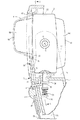
(実施例) 図1ないし図5は本発明に係る美容器具の実施例を示す。本発明における前後・左右・上下とは、図1および図4に示す交差矢印と、矢印の近傍に表示した前後・左右・上下の表記に従う。図1において美容器具は、グリップを兼ねる本体ケース1と、本体ケース1の前面側に配置されるシートホルダー2と、本体ケース1の上部に設けたヘッドブロック3とを備えている。美容器具を使用するときのシートホルダー2は、本体ケース1とともに片手で掴まれる。上下方向に長い長円形(縦長形状)のブロック状に形成したヘッドブロック3の後面および前面には、それぞれ第1接触ヘッド(接触ヘッド)5Aと第2接触ヘッド(接触ヘッド)5Bとを背中合わせ状に配置してある。
(Example) FIG. 1 thru | or FIG. 5 shows the Example of the beauty instruments based on this invention. In the present invention, “front / rear / left / right / upper / lower” follows the crossing arrows shown in FIGS. 1 and 4 and the front / rear / left / right / upper / lower notation displayed near the arrows. In FIG. 1, the beauty tool includes a main body case 1 that also serves as a grip, a sheet holder 2 that is disposed on the front side of the main body case 1, and a head block 3 that is provided on the upper portion of the main body case 1. The sheet holder 2 when using the beauty tool is held with the main body case 1 with one hand. A first contact head (contact head) 5A and a second contact head (contact head) 5B are back-to-back on the rear surface and the front surface of the head block 3 formed in an oblong (vertically long shape) block shape that is long in the vertical direction. It is arranged in.
側面から見るときの本体ケース1は、全体が部分円弧状に形成されて、その前面が突弧状に湾曲しており、本体ケース1の前後方向の機軸中心Pも、同様に突弧状に湾曲している。本体ケース1の後面には、電源投入用の電源ボタン6と、イオン導入時の電位を切り換える強弱ボタン7と、バイブレータ11への通電状態をオン・オフする振動ボタンなどが設けてある。本体ケース1の下半部の左右両側には、イオン導入時、あるいはイオン導出時の一方の電極となるアース板9が配置してあり、アース板9は電流調整回路の出力リードに接続されていて、他方の電極を兼ねる接触面18・19と協同して、イオン導入・導出用の微弱なパルス電流を人体に供給する。本体ケース1の内部には、2次電池10と、イオン導入・導出用のパルス電流を生成し、その電位を制御する電流調整回路などが収容してある。バイブレータ11はヘッドブロック3の内部に収容してあり、バイブレータ11による振動を肌面に作用させることによって、肌面をほぐすことができる。
When viewed from the side, the main body case 1 is entirely formed in a partial arc shape, and its front surface is curved in a projecting arc shape, and the longitudinal axis P of the main body case 1 is similarly curved in a projecting arc shape. ing. On the rear surface of the main body case 1, there are provided a power button 6 for turning on the power, a strength button 7 for switching the potential at the time of ion introduction, a vibration button for turning on / off the state of energization to the vibrator 11, and the like. On both the left and right sides of the lower half of the main body case 1, there are disposed ground plates 9 that serve as one of the electrodes when ions are introduced or ions are derived, and the ground plates 9 are connected to the output leads of the current adjustment circuit. Thus, in cooperation with the contact surfaces 18 and 19 that also serve as the other electrode, a weak pulse current for ion introduction and extraction is supplied to the human body. The body case 1 contains a secondary battery 10 and a current adjusting circuit that generates a pulse current for ion introduction / derivation and controls its potential. The vibrator 11 is accommodated in the head block 3, and the skin surface can be loosened by causing the vibration by the vibrator 11 to act on the skin surface.
本体ケース1に対するヘッドブロック3の姿勢を切り換えるために、本体ケース1の上部にU字状の凹み空間からなるヘッドハウジング15を設け、その空間にヘッドブロック3を収容している(図4参照)。また、ヘッドブロック3の左右に設けた支軸16を、左右一対の腕部17で前後回転可能に支持して、第1接触ヘッド5Aと、第2接触ヘッド5Bを択一的に使用姿勢に切り換え可能としている。この実施例における支軸16は、ヘッドブロック3の左右周面の上下中央で、ヘッドブロック3の左右周面の前後中央に配置してある。
In order to switch the posture of the head block 3 with respect to the main body case 1, a head housing 15 comprising a U-shaped recessed space is provided on the upper portion of the main body case 1, and the head block 3 is accommodated in the space (see FIG. 4). . Further, the support shafts 16 provided on the left and right sides of the head block 3 are supported by a pair of left and right arms 17 so as to be able to rotate back and forth, so that the first contact head 5A and the second contact head 5B can be alternatively used. Switchable. The support shaft 16 in this embodiment is arranged at the center of the head block 3 in the front and rear of the left and right peripheral surfaces and at the front and rear center of the left and right peripheral surfaces of the head block 3.
第1接触ヘッド5A、および第2接触ヘッド5Bは、それぞれチタン板を断面台形状にプレス成形して形成されており、その開口周縁壁がヘッドブロック3の前後面に固定してある。第1接触ヘッド5Aの突端には、緩やかな突弧面からなる縦長長円形状の接触面18が形成してあり、第2接触ヘッド5Bの突端には、緩やかな突弧面からなる円形の接触面19が形成してある。これらの接触面18・19は、それぞれ電流調整回路の出力リードに接続されていて、アース板9と協同してイオン導入・導出用の微弱なパルス電流を人体に供給する。なお、図示していないが、接触面18・19用の出力リードは、筒軸で形成した支軸16の内面を介して配線することにより、ヘッドブロック3の外面に露出しない状態で配線できる。
The first contact head 5 </ b> A and the second contact head 5 </ b> B are each formed by press-molding a titanium plate into a trapezoidal cross section, and the peripheral edge walls of the opening are fixed to the front and rear surfaces of the head block 3. A vertically long oval contact surface 18 made of a gentle projecting surface is formed on the projecting end of the first contact head 5A, and a circular shape made of a gentle projecting surface is formed on the projecting end of the second contact head 5B. A contact surface 19 is formed. These contact surfaces 18 and 19 are respectively connected to the output leads of the current adjusting circuit, and cooperate with the ground plate 9 to supply a weak pulse current for ion introduction / extraction to the human body. Although not shown, the output leads for the contact surfaces 18 and 19 can be wired without being exposed to the outer surface of the head block 3 by wiring through the inner surface of the support shaft 16 formed of a cylindrical shaft.
第1接触ヘッド5Aの接触面18は、主に首周りや胸周りを手入れするために設けられており、そのため、主に顔肌を手入れするための第2接触ヘッド5Bの接触面19に比べて、接触面18の面積が大きく設定してある。詳しくは、前者接触面18は、長円形状のヘッドブロック3の前後端面より、ひとまわり小さな長円形状に形成するが、ヘッドブロック3の前後端面の上下方向のほぼ全長にわたって縦長に形成することにより、その面積をできるだけ大きくしている。
The contact surface 18 of the first contact head 5A is provided mainly for cleaning around the neck and around the chest. Therefore, compared with the contact surface 19 of the second contact head 5B for mainly cleaning the facial skin. Thus, the area of the contact surface 18 is set large. Specifically, the former contact surface 18 is formed in an oval shape that is slightly smaller than the front and rear end surfaces of the oval head block 3, but is formed to be vertically long over almost the entire length of the front and rear end surfaces of the head block 3. Therefore, the area is made as large as possible.
先に説明したように、第2接触ヘッド5Bは主に顔肌の手入れを行うが、接触面19を小鼻の周りや目や口の周りなどの細かな部分に的確にあてがうために、各接触面18・19と支軸16との関係を次のように設定している。図1に示すように、支軸16の中心となる支軸中心Qから第2接触ヘッド5Bの接触面19までの突出寸法L2を、支軸中心Qから第1接触ヘッド5Aの接触面18までの突出寸法L1より大きく設定する。また、支軸中心Qを先に述べた機軸中心Pより、使用姿勢にした第2接触ヘッド5Bの側へ偏寄させて、支軸中心Qが機軸中心P上にある場合に比べて、使用姿勢にした第2接触ヘッド5Bを、本体ケース1の前面側へより大きく突出できるようにしている。また、第1接触ヘッド5Aを使用姿勢にした状態では、第2接触ヘッド5Bが本体ケース1の後面側へ大きく突出するのを緩和できるようにしている。さらに、第2接触ヘッド5Bを使用姿勢にした状態において、第2接触ヘッド5Bの中心軸Rを支軸中心Qよりも上方へ偏寄させている。これにより、使用姿勢にした状態の第2接触ヘッド5Bを、ヘッドブロック3の上端寄りに位置させることができる。
As described above, the second contact head 5B mainly cleans the facial skin, but in order to accurately apply the contact surface 19 to small parts such as around the nose and around the eyes and mouth, The relationship between the surfaces 18 and 19 and the support shaft 16 is set as follows. As shown in FIG. 1, the projecting dimension L2 from the support shaft center Q, which is the center of the support shaft 16, to the contact surface 19 of the second contact head 5B is from the support shaft center Q to the contact surface 18 of the first contact head 5A. Is set larger than the protruding dimension L1. Further, the spindle center Q is deviated from the machine axis center P described above toward the second contact head 5B in the use posture, and compared with the case where the spindle center Q is on the machine axis center P. The second contact head 5 </ b> B in the posture can be protruded more largely to the front side of the main body case 1. Further, when the first contact head 5 </ b> A is in the use posture, the second contact head 5 </ b> B can be prevented from greatly protruding toward the rear surface side of the main body case 1. Further, the center axis R of the second contact head 5B is biased upward from the support shaft center Q in a state where the second contact head 5B is in the use posture. As a result, the second contact head 5 </ b> B in the use posture can be positioned closer to the upper end of the head block 3.
第1、第2の両接触ヘッド5A・5Bを使用姿勢にした状態において、ヘッドブロック3を回動不能にロックするために、ヘッドブロック3と本体ケース1との間にロック機構を設けている。図2ないし図4に示すように、ロック機構は、ヘッドハウジング15の底面の左右中央に組み付けられるロックピン(ロック突起)21と、ヘッドブロック3の周面の上下に形成されるロック凹部22と、ロックピン21をロック凹部22へ向かって係合付勢するロックばね23などで構成する。ロックピン21は、上端が半球状に丸められた上下に長い丸軸からなり、その中途部に抜け止め用のフランジ24が張り出してある。フランジ24より上側の軸部分を、本体ケース1に設けたガイド穴25でスライド案内することにより、ロックピン21はロック凹部22に落ち込み係合するロック位置と、ロック凹部22から抜け出るロック解除位置との間で上下スライドできる。ロックばね23は圧縮コイル形のばねからなり、ロックピン21の下端と本体ケース1の内部に設けたばね受座26との間に配置してある。
A lock mechanism is provided between the head block 3 and the main body case 1 in order to lock the head block 3 so that it cannot rotate when both the first and second contact heads 5A and 5B are in the use posture. . As shown in FIGS. 2 to 4, the lock mechanism includes a lock pin (lock protrusion) 21 assembled at the left and right center of the bottom surface of the head housing 15, and a lock recess 22 formed above and below the peripheral surface of the head block 3. The lock pin 21 includes a lock spring 23 that engages and biases the lock pin 21 toward the lock recess 22. The lock pin 21 has a vertically long round shaft whose upper end is rounded into a hemispherical shape, and a flange 24 for preventing the lock 24 from protruding in the middle. By sliding and guiding the shaft portion above the flange 24 through the guide hole 25 provided in the main body case 1, the lock pin 21 falls into and engages with the lock recess 22, and the lock release position where the lock recess 21 comes out of the lock recess 22. Can slide up and down. The lock spring 23 is formed of a compression coil spring and is disposed between the lower end of the lock pin 21 and a spring seat 26 provided inside the main body case 1.
シートホルダー2は、ヘッドブロック3の外面に被せ付けた含液シートMを押え保持するために設けてあり、本体ケース1の前面に被さる主壁28と、本体ケース1の左右側面およびヘッドブロック3の上周面に被さる周側壁29とを一体に備えている。主壁28および周側壁29は、それぞれ本体ケース1の湾曲形状に沿って、前面が突弧状に湾曲するように形成してある。周側壁29の下端両側は、揺動軸30で本体ケース1に対して前後揺動可能に連結してある。これにより、シートホルダー2はヘッドブロック3から分離する開放姿勢と、ヘッドブロック3と協同して含液シートMを挟持する使用姿勢との間で姿勢を変更することができる。
The sheet holder 2 is provided to hold and hold the liquid-containing sheet M placed on the outer surface of the head block 3, and includes a main wall 28 that covers the front surface of the main body case 1, the left and right side surfaces of the main body case 1, and the head block 3. And a peripheral side wall 29 covering the upper peripheral surface. The main wall 28 and the peripheral side wall 29 are formed so that the front surface is curved in a projecting arc shape along the curved shape of the main body case 1. Both sides of the lower end of the peripheral side wall 29 are connected to the main body case 1 by a swing shaft 30 so as to be swingable back and forth. As a result, the seat holder 2 can change its posture between an open posture in which the sheet holder 2 is separated from the head block 3 and a use posture in which the liquid-containing sheet M is sandwiched in cooperation with the head block 3.
シートホルダー2の主壁28の上部には、含液シートを押え保持する長円状の押え窓32が開口され、その下半部側に押え窓32の開口面積を第1、第2の各接触ヘッド5A・5Bに対応して調整する開口調整体33が組み付けてある。主壁28の本体ケース1との対向面で、押え窓32の下側の壁には、ロックピン21がロック凹部22から離脱するのを規制する規制片34が突設してある。規制片34の突端には、ロックピン21に係合するU字状の規制溝35が設けてある。図2および図3に示すように規制片34は、シートホルダー2を使用姿勢にした状態においてのみロックピン21と係合して、ヘッドブロック3の姿勢が変わるのを規制するが、シートホルダー2を開放姿勢にした状態では、ロックピン21はロック凹部22から離脱できる。したがって、この実施例におけるロック機構は、ヘッドブロック3を所定の姿勢で位置保持するクリック機構を兼ねることとなる。
An oval holding window 32 for holding and holding the liquid-containing sheet is opened on the upper part of the main wall 28 of the sheet holder 2, and the opening area of the holding window 32 is set to the first half and the second area on the lower half side thereof. An opening adjusting body 33 that is adjusted to correspond to the contact heads 5A and 5B is assembled. On the surface of the main wall 28 facing the main body case 1 and on the lower wall of the presser window 32, a restricting piece 34 for restricting the lock pin 21 from being detached from the lock concave portion 22 is projected. A U-shaped restriction groove 35 that engages with the lock pin 21 is provided at the protruding end of the restriction piece 34. As shown in FIGS. 2 and 3, the restricting piece 34 engages with the lock pin 21 only in a state where the seat holder 2 is in the use posture, and restricts the posture of the head block 3 from changing. The lock pin 21 can be detached from the lock recess 22 in the open position. Therefore, the lock mechanism in this embodiment also serves as a click mechanism for holding the head block 3 in a predetermined posture.
図5に示すように開口調整体33は、上下に長い長方形状の板状体からなり、その上端に半円状の押え凹部37が設けてある。開口調整体33を上下にスライド切り換えするために、その左右両側に設けたスライド溝38を、周側壁29の内面に設けた左右一対のガイド突起39でスライド案内し、さらに開口調整体33の壁面中央に開口したスライド開口40を、先の規制片34でスライド案内している。また、シートホルダー2の主壁28の前面に設けた切り換えボタン41を開口調整体33に固定して、切り換えボタン41を主壁28に形成したスライド溝42に沿って上下にスライドすることにより、開口調整体33を上下に切り換えられるようにしている。
As shown in FIG. 5, the opening adjustment body 33 is formed of a rectangular plate-like body that is long in the vertical direction, and a semicircular holding recess 37 is provided at the upper end thereof. In order to slide the opening adjusting body 33 up and down, the slide grooves 38 provided on the left and right sides thereof are slid and guided by a pair of left and right guide protrusions 39 provided on the inner surface of the peripheral side wall 29, and the wall surface of the opening adjusting body 33 is further changed. The slide opening 40 opened in the center is slid and guided by the previous restriction piece 34. Further, by fixing the switching button 41 provided on the front surface of the main wall 28 of the seat holder 2 to the opening adjusting body 33 and sliding the switching button 41 up and down along the slide groove 42 formed in the main wall 28, The opening adjusting body 33 can be switched up and down.
スライド開口40の左右両側には、上下方向のばね腕からなるクリックばね43が設けてあり、クリックばね43が主壁28の内面に設けたクリック突起44を乗り越えることにより、開口調整体33を上方の進出位置と、下方の後退位置において位置保持できる。押え窓32の開口内縁と、開口調整体33の開口内縁には、それぞれ含液シートMをヘッドブロック3に向かって押し付ける押圧リブ45・46が半円状に突設してある。本体ケース1の前面には、規制片34の出入りを許す窓47が開口してある(図2参照)。
On both the left and right sides of the slide opening 40, there are provided click springs 43 composed of vertical spring arms. When the click springs 43 get over the click protrusions 44 provided on the inner surface of the main wall 28, the opening adjusting body 33 is moved upward. The position can be maintained at the advanced position and the retracted position below. Pressing ribs 45 and 46 that press the liquid-containing sheet M toward the head block 3 project in a semicircular shape at the opening inner edge of the pressing window 32 and the opening inner edge of the opening adjusting body 33, respectively. A window 47 that allows the restricting piece 34 to enter and exit is opened on the front surface of the main body case 1 (see FIG. 2).
以上のように構成した美容器具は、以下に説明する要領で使用する。顔肌の手入れを行う場合には、図2に示すように、第2接触ヘッド5Bを使用姿勢にしたのち、化粧水が化粧用の綿マットに含浸してある含液シートMを、第2接触ヘッド5Bの接触面19に被せ付ける。つぎに、開口調整体33を上方の進出位置に切り換えた状態で、シートホルダー2を使用姿勢にして本体ケース1に被せ付ける。これにより、含液シートMの周縁部分が、図2に想像線で示すように、第2接触ヘッド5Bと、シートホルダー2の押え窓32および押え凹部37とに挟持されて遊動不能に固定される。
The beauty instrument configured as described above is used in the manner described below. When cleaning the facial skin, as shown in FIG. 2, after the second contact head 5B is brought into the use posture, the liquid-containing sheet M in which the cosmetic cotton mat is impregnated with the lotion is used as the second contact head 5B. It covers the contact surface 19 of the contact head 5B. Next, in a state where the opening adjustment body 33 is switched to the upper advanced position, the seat holder 2 is placed in a use posture and is placed on the main body case 1. As a result, as shown by an imaginary line in FIG. 2, the peripheral portion of the liquid-containing sheet M is sandwiched between the second contact head 5 </ b> B, the press window 32 and the press recessed portion 37 of the sheet holder 2, and is fixed so as not to float. The
上記のように、シートホルダー2を使用姿勢にした状態では、規制片34が窓47から本体ケース1内へ入り込み、その規制溝35がロックピン21のフランジ24より下側のピン軸に係合して、ロックピン21のロック解除移動を規制する。この状態で、電源ボタン6をオン操作してバイブレータ11を起動し、さらに強弱ボタン7を調整して、第2接触ヘッド5Bおよびアース板9に印加される電圧を調整する。この状態で、アース板9を本体ケース1およびシートホルダー2と同時に握り締め、第2接触ヘッド5Bを顔肌に押し付けて摺動する。このとき、顔肌は接触面19に対して化粧水を介して電気的に導通しており、さらに手のひらがアース板9と導通しているので、顔肌には微弱なパルス電流が供給される。なお、イオン導出用のパルス電流を供給して顔肌などの微細な汚れを落とす場合と、イオン導入用のパルス電流を供給して保湿成分を肌に浸透させる場合とで、アース板9と接触面19に供給される電流の極性は逆になる。バイブレータ11は、図示していないスイッチノブを切り換えることによりオン・オフでき、ユーザーの好みや肌面の状態に応じて、バイブレータ11を駆動した状態と、停止した状態にして美容器具を使用できる。
As described above, when the seat holder 2 is in the use posture, the restricting piece 34 enters the main body case 1 from the window 47, and the restricting groove 35 engages with the pin shaft below the flange 24 of the lock pin 21. Thus, the unlocking movement of the lock pin 21 is restricted. In this state, the power button 6 is turned on to activate the vibrator 11, and the strength button 7 is adjusted to adjust the voltage applied to the second contact head 5B and the ground plate 9. In this state, the ground plate 9 is squeezed simultaneously with the main body case 1 and the sheet holder 2, and the second contact head 5B is slid against the face skin. At this time, the face skin is electrically connected to the contact surface 19 through the skin lotion, and further, the palm is connected to the ground plate 9, so that a weak pulse current is supplied to the face skin. . In addition, when supplying a pulse current for derivation of ions to remove fine dirt such as facial skin, and when supplying a pulse current for ion introduction to infiltrate the moisturizing component into the skin, contact with the earth plate 9 The polarity of the current supplied to the surface 19 is reversed. The vibrator 11 can be turned on and off by switching a switch knob (not shown), and the beauty tool can be used in a state where the vibrator 11 is driven and a state where the vibrator 11 is stopped according to the user's preference and the skin condition.
使用状態において、第1接触ヘッド5Aと第2接触ヘッド5Bにパルス電流を同時に供給すると、顔肌に供給すべきパルス電流が短絡されるおそれがある。たとえば第2接触ヘッド5Bを使用姿勢にした状態において、アース板9を握っている手指が第1接触ヘッド5Aに触れると、パルス電流が手指を介して短絡され、パルス電流を顔肌に供給できなくなる。こうした不具合を防ぐために、第2接触ヘッド5Bを使用姿勢にした状態では、第1接触ヘッド5Aへのパルス電流の供給を停止し、逆に、第1接触ヘッド5Aを使用姿勢にした状態では、第2接触ヘッド5Bへのパルス電流の供給を停止することが好ましい。
If a pulse current is supplied to the first contact head 5A and the second contact head 5B at the same time in use, the pulse current to be supplied to the face skin may be short-circuited. For example, in a state where the second contact head 5B is in the use posture, when a finger holding the ground plate 9 touches the first contact head 5A, the pulse current is short-circuited through the finger, and the pulse current can be supplied to the facial skin. Disappear. In order to prevent such a problem, in the state where the second contact head 5B is in the use posture, the supply of the pulse current to the first contact head 5A is stopped, and conversely, in the state where the first contact head 5A is in the use posture, It is preferable to stop supplying the pulse current to the second contact head 5B.
上記のように、パルス電流が手指を介して短絡されるのを防ぐために、不使用姿勢になっている側の接触ヘッドへのパルス電流の供給を停止する美容器具は、次の形態で実施できる。
グリップを兼ねる本体ケース1と、本体ケース1の上部に配置されて、支軸16を中心にして回転可能に支持されるヘッドブロック3を備えており、ヘッドブロック3の前面および後面には、第1接触ヘッド5Aと第2接触ヘッド5Bとが背中合わせ状に配置されており、本体ケース1の外面には、イオン導入時、あるいはイオン導出時の一方の電極となるアース板9が配置されており、第1接触ヘッド5Aの接触面18および第2接触ヘッド5Bの接触面19と、アース板9とは、電流調整回路80から出力されるパルス電流を人体に対して協同して供給できるようになっており、両接触ヘッド5A・5Bのいずれか一方を使用姿勢にした状態において、不使用姿勢になっている側の接触ヘッドへのパルス電流の供給を停止することを特徴とする美容器具。
不使用姿勢になっている側の接触ヘッドへのパルス電流の供給が、ヘッドブロック3の回転動作に連動して停止される上記の美容器具。なお、ヘッドブロック3は、図1に示すように水平の支軸16を中心にして回転する場合と、図14に示すように垂直の支軸16を中心にして回転する場合のいずれであってもよい。
As described above, in order to prevent the pulse current from being short-circuited through the fingers, the beauty device for stopping the supply of the pulse current to the contact head on the non-use posture can be implemented in the following form .
A main body case 1 that also serves as a grip, and a head block 3 that is disposed on the upper portion of the main body case 1 and is supported so as to be rotatable about a support shaft 16, are provided on the front and rear surfaces of the head block 3. The first contact head 5A and the second contact head 5B are arranged back to back, and a ground plate 9 serving as one electrode at the time of ion introduction or ion extraction is arranged on the outer surface of the main body case 1. The contact surface 18 of the first contact head 5A, the contact surface 19 of the second contact head 5B, and the ground plate 9 can cooperatively supply the pulse current output from the current adjustment circuit 80 to the human body. In the state where either one of the contact heads 5A and 5B is in the use posture, the supply of the pulse current to the contact head in the non-use posture is stopped. Beauty instrument for.
The beauty tool described above, wherein the supply of the pulse current to the contact head on the non-use posture is stopped in conjunction with the rotation operation of the head block 3. The head block 3 is either rotated around a horizontal spindle 16 as shown in FIG. 1 or rotated around a vertical spindle 16 as shown in FIG. Also good.
所定の使用時間が経過して肌面の手入れが終了したら、第2接触ヘッド5Bを顔肌から離して電源ボタン6をオフ操作する。さらに、シートホルダー2を本体ケース1から分離して開放姿勢にする。この状態で、含液シートMを第2接触ヘッド5Bから取り外して廃棄する。なお、第2接触ヘッド5Bを使用姿勢にした状態から、第1接触ヘッド5Aを使用姿勢に切り換える場合には、ヘッドブロック3を図2において時計回転方向へ回転操作する。また、逆の場合には、ヘッドブロック3を図3において反時計回転方向へ回転操作する。これは、ヘッドブロック3を先に説明した回転方向とは逆向きに回転操作して第1、第2の各接触ヘッド5A・5Bの姿勢を変更するとき、第2接触ヘッド5Bがヘッドハウジング15の前後の開口縁に接当するからである。このように、第1、第2の各接触ヘッド5A・5Bの姿勢を変更する時に、ヘッドブロック3を往復回転させるようにすると、接触面18・19用の出力リードが捻じれるのを防止して、断線の原因となるのを解消できる。
When the skin has been cleaned after a predetermined usage time has elapsed, the second contact head 5B is moved away from the face skin and the power button 6 is turned off. Further, the seat holder 2 is separated from the main body case 1 to be in an open posture. In this state, the liquid-containing sheet M is removed from the second contact head 5B and discarded. When the first contact head 5A is switched from the state in which the second contact head 5B is in the use posture to the use posture, the head block 3 is rotated in the clockwise direction in FIG. In the reverse case, the head block 3 is rotated counterclockwise in FIG. This is because when the head block 3 is rotated in the direction opposite to the rotation direction described above to change the postures of the first and second contact heads 5A and 5B, the second contact head 5B is moved to the head housing 15. It is because it touches the opening edge before and behind. As described above, when the postures of the first and second contact heads 5A and 5B are changed, if the head block 3 is reciprocally rotated, the output leads for the contact surfaces 18 and 19 are prevented from being twisted. Thus, it is possible to eliminate the cause of disconnection.
首周りや胸周りの肌面の手入れを行う場合には、図3に示すように、第1接触ヘッド5Aを使用姿勢にしてヘッドブロック3をロック機構でロックしたのち、切り換えボタン41を下方へスライド操作して、開口調整体33を下方の後退位置に位置させる。次に、先に説明した要領で含液シートMをシートホルダー2で挟持固定して、面積が大きな接触面18の全体を含液シートMで覆う。以後は、電源ボタン6をオン操作してバイブレータ11を起動し、さらに強弱ボタン7を調整した状態で、アース板9を本体ケース1およびシートホルダー2と同時に握り締め、第1接触ヘッド5Aを肌に押し付けて摺動させる。
When cleaning the skin surface around the neck and the chest, as shown in FIG. 3, after the first contact head 5A is used and the head block 3 is locked by the lock mechanism, the switching button 41 is moved downward. The opening adjustment body 33 is positioned at the lower retracted position by sliding operation. Next, the liquid-containing sheet M is sandwiched and fixed by the sheet holder 2 in the manner described above, and the entire contact surface 18 having a large area is covered with the liquid-containing sheet M. Thereafter, the power button 6 is turned on to activate the vibrator 11, and the grounding plate 9 is squeezed simultaneously with the body case 1 and the seat holder 2 with the strength button 7 adjusted, and the first contact head 5A is placed on the skin. Press to slide.
以上のように、本発明に係る美容器具によれば、手入れすべき肌面の面積や構造等の違いに応じて、第1、第2の接触ヘッド5A・5Bを使い分けることができるので、顔肌や、首周りあるいは胸周りの肌面の手入れを好適に行える。また、ヘッドブロック3を本体ケース1に対して回動操作するだけで、ロック凹部22をロックピン21に係合させて、第1、第2の各接触ヘッド5A・5Bを使用位置に固定できるので、使用すべき接触ヘッド5A・5Bの切り換えを簡便に行うことができ、使い勝手に優れた美容器具とすることができる。
As described above, according to the beauty instrument according to the present invention, the first and second contact heads 5A and 5B can be used properly according to the difference in the area and structure of the skin surface to be cleaned. Care for the skin and the skin surface around the neck or chest can be suitably performed. Further, the first and second contact heads 5A and 5B can be fixed at the use positions by simply engaging the head block 3 with respect to the main body case 1 to engage the lock recess 22 with the lock pin 21. Therefore, the contact heads 5A and 5B to be used can be easily switched, and a beauty device with excellent usability can be obtained.
図6から図19において、上記の美容器具の一部を変更した別の実施例について説明する。なお、図6から図19における美容器具については、上記の実施例と異なる部分を主に説明し、上記の実施例と同じ部材には同じ符号を付してその説明を省略する。
6 to 19, another embodiment in which a part of the beauty tool is changed will be described. 6 to FIG. 19, the different parts from the above embodiment will be mainly described, and the same members as those in the above embodiment will be given the same reference numerals and the description thereof will be omitted.
図6に示す美容器具は、ロック機構を支軸16の近傍のヘッドブロック3の一側面と、ヘッドハウジング15の片方の腕部17との間に設けるようにした。詳しくは、支軸16の上下にロック凹部22を凹み形成し、支軸16より下方の腕部17の壁面でロックピン21を出没自在に案内した。また、ロックピン21の軸端21aを腕部17の外側面から突出させて、ロックピン21がロック凹部22に落ち込み係合した状態において、軸端21aをシートホルダー2の周側壁29で受け止めて、ロックピン21がロック解除状態に切り換わるのを規制できるようにした。この場合の周側壁29は、先の実施例における規制片34と同じ機能を発揮するので、規制片34や窓47を省略できる。上記のように、支軸16の上下にロック凹部22を設けると、ロック凹部22の外面を腕部17で常に覆うことができるので、外観上の印象をすっきりしたものにして意匠性を向上できる。この実施例におけるロック機構はクリック機構を兼ねている。
In the beauty tool shown in FIG. 6, the lock mechanism is provided between one side surface of the head block 3 near the support shaft 16 and one arm portion 17 of the head housing 15. Specifically, a lock recess 22 is formed on the upper and lower sides of the support shaft 16, and the lock pin 21 is guided in a freely retractable manner on the wall surface of the arm portion 17 below the support shaft 16. Further, the shaft end 21 a of the lock pin 21 protrudes from the outer surface of the arm portion 17, and the shaft end 21 a is received by the peripheral side wall 29 of the seat holder 2 in a state where the lock pin 21 falls into and engages with the lock recess 22. The switching of the lock pin 21 to the unlocked state can be restricted. Since the peripheral side wall 29 in this case exhibits the same function as the restriction piece 34 in the previous embodiment, the restriction piece 34 and the window 47 can be omitted. As described above, when the lock recess 22 is provided above and below the support shaft 16, the outer surface of the lock recess 22 can always be covered with the arm portion 17, so that the appearance can be made clear and the design can be improved. . The lock mechanism in this embodiment also serves as a click mechanism.
図7に示す美容器具は、ヘッドハウジング15とシートホルダー2を利用して、ヘッドブロック3を固定保持できるようにする点が、図1から図5で説明した美容器具と異なる。詳しくは、ヘッドブロック3の周面の上下に位置決め用の第1突起51と第2突起52とを設け、ヘッドハウジング15の底面に、第1、第2の各突起51・52を受け止めるストッパー53を設ける。さらに、シートホルダー2の押え窓32の開口内縁に第1回転規制部54を設け、開口調整体33の内面に第2回転規制部55を設ける。第1回転規制部54は押圧リブ45を兼ねている。
The beauty tool shown in FIG. 7 is different from the beauty tool described in FIGS. 1 to 5 in that the head block 3 can be fixedly held using the head housing 15 and the sheet holder 2. Specifically, a first protrusion 51 and a second protrusion 52 for positioning are provided above and below the peripheral surface of the head block 3, and a stopper 53 that receives the first and second protrusions 51 and 52 on the bottom surface of the head housing 15. Is provided. Further, the first rotation restricting portion 54 is provided on the inner edge of the opening of the presser window 32 of the sheet holder 2, and the second rotation restricting portion 55 is provided on the inner surface of the opening adjusting body 33. The first rotation restricting portion 54 also serves as the pressing rib 45.
図7(a)に示すように、第2接触ヘッド5Bを使用姿勢にし、かつシートホルダー2を使用姿勢にした状態においては、第2回転規制部55がヘッドブロック3の前面下部に押し付けられて、第2突起52がストッパー53の前面で受け止められる。したがって、ヘッドブロック3が支軸16の回りに回動するのを規制できる。また、図7(b)に示すように、第1接触ヘッド5Aを使用姿勢にし、かつシートホルダー2を使用姿勢にした状態においては、第1回転規制部54がヘッドブロック3の前面上部に押し付けられて、第1突起51がストッパーの後面で受け止められる。したがって、ヘッドブロック3が支軸16の回りに回動するのを規制できる。このように、ヘッドハウジング15とシートホルダー2を利用して、ヘッドブロック3をロック保持できるようにすると、先の実施例におけるロックピン21、ロックばね23、規制片34などを省略してロック機構の構造を簡素化できる。
As shown in FIG. 7A, in the state where the second contact head 5B is in the use posture and the seat holder 2 is in the use posture, the second rotation restricting portion 55 is pressed against the lower front surface of the head block 3. The second protrusion 52 is received on the front surface of the stopper 53. Therefore, the head block 3 can be restricted from rotating around the support shaft 16. Further, as shown in FIG. 7B, in a state where the first contact head 5A is in the use posture and the sheet holder 2 is in the use posture, the first rotation restricting portion 54 is pressed against the upper front surface of the head block 3. Thus, the first protrusion 51 is received by the rear surface of the stopper. Therefore, the head block 3 can be restricted from rotating around the support shaft 16. As described above, when the head block 3 can be locked and held using the head housing 15 and the seat holder 2, the lock pin 21, the lock spring 23, the restricting piece 34 and the like in the previous embodiment are omitted, and the lock mechanism. Can be simplified.
図8に示す美容器具は、ロック機構を支軸16と腕部17との間に設ける点が先の実施例と異なる。そこでは、腕部17の内部に設けたガイド穴25でロックピン21を上下スライド自在に案内し、ロックピン21をロックばね23でロック凹部22へ向かって係合付勢している。支軸16にはロックリング58が同行回転可能に固定してあり、その周面の上下にロック凹部22が形成してある。腕部17の外面には、ロックピン21をロックばね23の付勢力に抗してロック解除操作するロック解除ノブ(ロック解除体)59が設けてある。シートホルダー2の周側壁29には、シートホルダー2を使用姿勢に切り換えた状態において、ロック解除ノブ59の外面を覆う規制壁60が設けてある。このように、シートホルダー2を利用して、ロック解除ノブ59の切り換え操作を規制すると、美容器具を使用する際に、誤ってロック解除ノブ59がロック解除操作されるのを確実に防止できる。
The beauty instrument shown in FIG. 8 is different from the previous embodiment in that a lock mechanism is provided between the support shaft 16 and the arm portion 17. In this case, the lock pin 21 is guided by a guide hole 25 provided in the arm portion 17 so as to be slidable up and down, and the lock pin 21 is engaged and biased toward the lock recess 22 by a lock spring 23. A lock ring 58 is fixed to the support shaft 16 so as to be able to rotate together. A lock recess 22 is formed above and below the peripheral surface. On the outer surface of the arm portion 17, there is provided an unlocking knob (unlocking body) 59 for unlocking the lock pin 21 against the urging force of the lock spring 23. The peripheral wall 29 of the seat holder 2 is provided with a regulating wall 60 that covers the outer surface of the unlocking knob 59 when the seat holder 2 is switched to the use posture. In this way, by restricting the switching operation of the unlocking knob 59 using the seat holder 2, it is possible to reliably prevent the unlocking knob 59 from being accidentally unlocked when using a beauty tool.
図9に示す美容器具は、図8で説明したロック機構と同じ構造のロック機構を支軸16と腕部17との間に設けるが、シートホルダー2の構造が図8の美容器具とは異なっている。そこでは、押え窓32を備えた上下寸法が小さな主壁28と、主壁28の左右両側に連続する周側壁29とでシートホルダー2を構成し、周側壁29の上部を腕部17の上端外面に設けた揺動軸30で軸支するようにした。シートホルダー2を揺動軸30で軸支するために、腕部17の上端はヘッドブロック3の上周面より上方へ突出させてある。シートホルダー2の周側壁29は、ロック解除ノブ59の外面を覆う規制壁60を兼ねており、したがって、シートホルダー2を使用姿勢に切り換えた状態において、ロック解除ノブ59の外面を規制壁60で覆って、ロック解除ノブ59が誤ってロック解除操作されるのを解消できる。
9 is provided with a locking mechanism having the same structure as the locking mechanism described in FIG. 8 between the support shaft 16 and the arm portion 17, but the structure of the seat holder 2 is different from that in FIG. ing. There, the sheet holder 2 is constituted by a main wall 28 having a presser window 32 and having a small vertical dimension and a peripheral side wall 29 continuous on the left and right sides of the main wall 28, and the upper portion of the peripheral side wall 29 is the upper end of the arm portion 17. The shaft is supported by a rocking shaft 30 provided on the outer surface. In order to support the seat holder 2 with the swing shaft 30, the upper end of the arm portion 17 protrudes upward from the upper peripheral surface of the head block 3. The peripheral side wall 29 of the seat holder 2 also serves as a regulating wall 60 that covers the outer surface of the unlocking knob 59. Therefore, when the seat holder 2 is switched to the use posture, the outer surface of the unlocking knob 59 is covered by the regulating wall 60. It is possible to eliminate the accidental unlocking operation of the unlocking knob 59.
図10に示す美容器具は、図8で説明したロック機構と同じ構造のロック機構を支軸16と腕部17との間に設けるが、シートホルダー2の構造が図8、図9の美容器具とは異なっている。シートホルダー2は、押え窓32を備えた上下寸法が小さな主壁28と、主壁28の上下に連続する周側壁29と、主壁28の左右両側に連続する一対の規制壁60とで、キャップ状に構成してある。周側壁29の突端には、ヘッドブロック3の上下周面の後縁に係脱する係合リブ63が設けてある。想像線で示すように、シートホルダー2をヘッドブロック3に装着した状態では、規制壁60でロック解除ノブ59の外面を覆って、ロック解除ノブ59が誤ってロック解除操作されるのを解消できる。このように、シートホルダー2はヘッドブロック3に対して必ずしも連結する必要はない。
The beauty tool shown in FIG. 10 is provided with a lock mechanism having the same structure as the lock mechanism described in FIG. 8 between the support shaft 16 and the arm portion 17, but the structure of the seat holder 2 is the beauty tool shown in FIGS. Is different. The seat holder 2 includes a main wall 28 having a presser window 32 and a small vertical dimension, a peripheral side wall 29 continuous above and below the main wall 28, and a pair of restriction walls 60 continuous on both the left and right sides of the main wall 28. It is configured in a cap shape. Engaging ribs 63 that engage and disengage with the rear edges of the upper and lower peripheral surfaces of the head block 3 are provided at the protruding ends of the peripheral side walls 29. As indicated by an imaginary line, when the seat holder 2 is mounted on the head block 3, the lock release knob 59 can be prevented from being accidentally unlocked by covering the outer surface of the lock release knob 59 with the restriction wall 60. . Thus, the sheet holder 2 is not necessarily connected to the head block 3.
図11に示す美容器具は、図8で説明したロック機構とほぼ同じ構造のロック機構を支軸16と腕部17との間に設けるが、ロックリング58の周面の8個所にロック凹部22を形成する点が異なる。このように、ロックリング58に多数個のロック凹部22が設けてあると、第1接触ヘッド5Aを使用姿勢にした状態と、第2接触ヘッド5Bを使用姿勢にした状態と、両状態の中間の姿勢にした状態において、ヘッドブロック3を回転不能に位置保持できる。したがってユーザーは、第1、第2の各接触ヘッド5A・5Bを好みに応じて傾斜させた状態で使用でき、たとえば、図11に示すように、第2接触ヘッド5Bが斜め上向きに傾斜する状態にヘッドブロック3をロック保持して、肌面の手入れを行うことができる。
The beauty tool shown in FIG. 11 is provided with a lock mechanism having substantially the same structure as the lock mechanism described in FIG. 8 between the support shaft 16 and the arm portion 17, and lock recesses 22 are provided at eight locations on the peripheral surface of the lock ring 58. Is different. As described above, when the lock ring 58 is provided with a large number of lock recesses 22, the first contact head 5A is in the use posture, the second contact head 5B is in the use posture, and the intermediate state between the two states. In this state, the head block 3 can be held in a non-rotatable position. Therefore, the user can use the first and second contact heads 5A and 5B in an inclined state according to his / her preference. For example, as shown in FIG. 11, the second contact head 5B is inclined obliquely upward. The head block 3 can be locked and the skin surface can be cared for.
図12に示す美容器具は、長円状に形成したヘッドブロック3の前後に、上下に長い第1接触ヘッド5Aと、第1接触ヘッド5Aより上下寸法が小さな第2接触ヘッド5Bとを設け、使用姿勢にした第2接触ヘッド5Bの中心軸R、および支軸中心Qのそれぞれを、ヘッドブロック3の上下中央よりも上方へ偏寄する状態で配置した。また、第1接触ヘッド5Aは、ヘッドブロック3の縦長形状と相似の縦長の長円形状に形成した。さらに、図13に示すように、ロックリング58の周面にラチェット歯70とストッパー爪71を形成し、ロックリング58の下方にラチェット歯70と係合するラチェット爪72を設けた。ラチェット爪72はラチェット軸73の回りに上下揺動でき、捻じりコイル形のばね74でラチェット軸73と係合する向きに揺動付勢してある。腕部17の外面にはラチェット爪72を係合解除操作する解除ノブ75が設けてあり、解除ノブ75とラチェット爪72とはピン76を介して連結してある。符号77は、第1接触ヘッド5Aを使用姿勢にした状態においてストッパー爪71を受け止める規制突起であり、腕部17の内面に突設してある。
The beauty tool shown in FIG. 12 is provided with a first contact head 5A that is long in the vertical direction and a second contact head 5B that is smaller in the vertical dimension than the first contact head 5A before and after the oblong head block 3. The center axis R and the support shaft center Q of the second contact head 5B in the use posture are arranged so as to be offset upward from the vertical center of the head block 3. Further, the first contact head 5 </ b> A was formed in a vertically long oval shape similar to the vertically long shape of the head block 3. Furthermore, as shown in FIG. 13, ratchet teeth 70 and stopper claws 71 are formed on the peripheral surface of the lock ring 58, and ratchet claws 72 that engage with the ratchet teeth 70 are provided below the lock ring 58. The ratchet pawl 72 can swing up and down around the ratchet shaft 73, and is oscillated and biased in a direction to engage with the ratchet shaft 73 by a torsion coil spring 74. A release knob 75 for releasing the engagement of the ratchet pawl 72 is provided on the outer surface of the arm portion 17, and the release knob 75 and the ratchet pawl 72 are connected via a pin 76. Reference numeral 77 denotes a restricting protrusion that receives the stopper claw 71 in a state where the first contact head 5 </ b> A is in a use posture, and protrudes from the inner surface of the arm portion 17.
上記のように、第2接触ヘッド5Bの中心軸R、および支軸中心Qのそれぞれを、ヘッドブロック3の上下中央よりも上方へ偏寄させると、第1接触ヘッド5Aを使用位置に固定保持した状態の美容器具の上下方向の全長寸法を、第2接触ヘッド5Bを使用位置に固定保持した状態の美容器具の上下方向の全長寸法より大きくできる。図12に、前者全長寸法と後者全長寸法との差を符号Hで示している。このように、第1接触ヘッド5Aを使用位置にした状態において、その接触面18の大半の部分を腕部17より上方へ大きく突出させると、胸周りの肌面や、首周りの背中側の肌面の手入れを行う場合に、接触面18を肌面に的確にあてがうことができる。また、第2接触ヘッド5Bを使用姿勢にした状態における美容器具の上下方向の全長寸法を小さくして、顔肌の手入れを軽快に行うことができる。
As described above, when each of the central axis R and the support shaft center Q of the second contact head 5B is offset upward from the vertical center of the head block 3, the first contact head 5A is fixedly held at the use position. The full length dimension of the beauty tool in the vertical direction can be made larger than the full length dimension of the beauty tool in the state where the second contact head 5B is fixedly held at the use position. In FIG. 12, the difference between the former full length dimension and the latter full length dimension is indicated by the symbol H. In this way, when the first contact head 5A is in the use position, if most of the contact surface 18 protrudes largely above the arm portion 17, the skin surface around the chest and the back side around the neck When performing skin care, the contact surface 18 can be accurately applied to the skin surface. Further, the facial skin can be easily cared for by reducing the overall length in the vertical direction of the beauty tool when the second contact head 5B is in the use posture.
図12(b)に示すように、第1接触ヘッド5Aを使用位置にした状態においては、接触面18の大半の部分が腕部17より上方へ大きく突出するため、支軸16に大きな傾動モーメントが作用する。しかし、ラチェット歯70をラチェット爪72で受け止めているので、ヘッドブロック3が時計回転方向へ回動することはなく、第1接触ヘッド5Aを安定した状態で使用できる。第2接触ヘッド5Bを使用位置に変位させる場合には、解除ノブ75を下方へスライド操作して、ラチェット爪72とラチェット歯70の係合を解除し、ヘッドブロック3を時計回転方向へ回動する。このとき、ヘッドハウジング15の前部に設けた規制壁15aでヘッドブロック3を受け止めることにより、第2接触ヘッド5Bを使用姿勢に位置決めできる。なお、使用姿勢にした第2接触ヘッド5Bが、反時計回転方向へ回転するのを防ぐために、別途クリック機構を設けることができる。
As shown in FIG. 12B, in the state where the first contact head 5A is in the use position, most of the contact surface 18 protrudes largely upward from the arm portion 17, so that a large tilting moment is exerted on the support shaft 16. Works. However, since the ratchet teeth 70 are received by the ratchet pawl 72, the head block 3 does not rotate in the clockwise direction, and the first contact head 5A can be used in a stable state. When the second contact head 5B is displaced to the use position, the release knob 75 is slid downward to release the engagement between the ratchet pawl 72 and the ratchet teeth 70, and the head block 3 is rotated in the clockwise direction. To do. At this time, the second contact head 5B can be positioned in the use posture by receiving the head block 3 with the restriction wall 15a provided at the front portion of the head housing 15. In order to prevent the second contact head 5B in the use posture from rotating in the counterclockwise direction, a separate click mechanism can be provided.
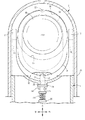
図14に示す美容器具は、ヘッドブロック3の下面中央に設けた支軸16を本体ケース1の上端壁に設けた軸受穴65で軸支して、ヘッドブロック3を支軸16の回りに回転させて、各接触ヘッド5A・5Bを択一的に使用姿勢にできるようにした。また、ロック機構を本体ケース1とヘッドブロック3との間に設けて、各接触ヘッド5A・5Bを使用姿勢にした状態において、ヘッドブロック3を位置保持できるようにした。この場合のロック機構は、ロック凹部22をヘッドブロック3の下面の支軸16の前後に設ける点以外は、図1から図5で説明したロック機構と実質的に同じであるので、その説明を省略する。この実施例においては、ヘッドブロック3を垂直軸回りに回転させるので、ヘッドハウジング15は省略する。
In the beauty tool shown in FIG. 14, a support shaft 16 provided at the center of the lower surface of the head block 3 is supported by a bearing hole 65 provided in the upper end wall of the main body case 1, and the head block 3 is rotated around the support shaft 16. As a result, each of the contact heads 5A and 5B can be alternatively used. In addition, a lock mechanism is provided between the main body case 1 and the head block 3 so that the head block 3 can be held in a position in which the contact heads 5A and 5B are in a use posture. The lock mechanism in this case is substantially the same as the lock mechanism described with reference to FIGS. 1 to 5 except that the lock recess 22 is provided before and after the support shaft 16 on the lower surface of the head block 3. Omitted. In this embodiment, since the head block 3 is rotated around the vertical axis, the head housing 15 is omitted.
図14に示す美容器具においても、図1の美容器具と同様に、支軸16の中心となる支軸中心Qから第2接触ヘッド5Bの接触面19までの突出寸法L2を、支軸中心Qから第1接触ヘッド5Aの接触面18までの突出寸法L1より大きく設定している。また、支軸中心Qを本体ケース1の機軸中心Pより、使用姿勢にした第2接触ヘッド5Bの側へ偏寄させて、支軸中心Qが機軸中心P上にある場合に比べて、使用姿勢にした第2接触ヘッド5Bを、本体ケース1の前面側へより大きく突出できるようにしている。
In the beauty tool shown in FIG. 14, similarly to the beauty tool in FIG. 1, the protrusion dimension L <b> 2 from the support shaft center Q that is the center of the support shaft 16 to the contact surface 19 of the second contact head 5 </ b> B is set to the support center Q. To a contact dimension 18 from the contact surface 18 of the first contact head 5A. Further, the support shaft center Q is offset from the machine shaft center P of the main body case 1 toward the second contact head 5B in the use posture, and compared to the case where the support shaft center Q is on the machine shaft center P. The second contact head 5 </ b> B in the posture can be protruded more largely to the front side of the main body case 1.
図15に示す美容器具は、図1で説明した美容器具と基本的に同じであるが、支軸16の支軸中心Qをヘッドブロック3の左右周面の前後中央よりも、第1接触ヘッド5Aの接触面18の側へ偏寄させるようにした(図15(a)参照)。また、支軸中心Qを本体ケース1の機軸中心Pより、使用姿勢にした第2接触ヘッド5Bの側へ偏寄させるようにした。以上のように支軸中心Qを偏寄させることにより、図1で説明した美容器具に比べて、支軸中心Qから第2接触ヘッド5Bの接触面19までの突出寸法L2をさらに大きくできる。また、図15(b)に示すように、第1接触ヘッド5Aを使用姿勢にした状態において、第2接触ヘッド5Bが本体ケース1の後面側へ大きく突出するのを緩和することができる。
The beauty tool shown in FIG. 15 is basically the same as the beauty tool described with reference to FIG. 1, but the first contact head is located at the support shaft center Q of the support shaft 16 rather than the front and rear centers of the left and right peripheral surfaces of the head block 3. It was made to deviate to the contact surface 18 side of 5A (refer Fig.15 (a)). Further, the support shaft center Q is offset from the machine shaft center P of the main body case 1 toward the second contact head 5B in the use posture. By offsetting the support shaft center Q as described above, the protrusion dimension L2 from the support shaft center Q to the contact surface 19 of the second contact head 5B can be further increased as compared with the beauty tool described in FIG. Further, as shown in FIG. 15 (b), the second contact head 5 </ b> B can be mitigated from greatly projecting to the rear surface side of the main body case 1 in a state where the first contact head 5 </ b> A is in the use posture.
図16に示す美容器具は、図14で説明した美容器具と基本的に同じであるが、支軸16の支軸中心Qをヘッドブロック3の左右周面の前後中央よりも、第1接触ヘッド5Aの接触面18の側へ偏寄させるようにした(図16(a)参照)。また、支軸中心Qを本体ケース1の機軸中心Pより、使用姿勢にした第2接触ヘッド5Bの側へ偏寄させるようにした(図16(b)参照)。以上のように支軸中心Qを偏寄させることにより、図15で説明した美容器具と同等の作用効果を発揮できる。
The beauty tool shown in FIG. 16 is basically the same as the beauty tool described with reference to FIG. 14, but the first contact head is located at the support shaft center Q of the support shaft 16 rather than the front and rear centers of the left and right peripheral surfaces of the head block 3. It was made to deviate to the contact surface 18 side of 5A (refer Fig.16 (a)). Further, the support shaft center Q is offset from the machine shaft center P of the main body case 1 toward the second contact head 5B in the use posture (see FIG. 16B). By deviating the support shaft center Q as described above, it is possible to exhibit the same effect as the beauty instrument described in FIG.
上記の各実施例では、ヘッドブロック3の前面と後面に、第1接触ヘッド5Aと第2接触ヘッド5Bを設けたがその必要はなく、図17に示すように、ヘッドブロック3の前後面のいずれか一方に第1接触ヘッド5Aを設け、ヘッドブロック3の周側面に第2接触ヘッド5Bを設けることができる。その場合には、ヘッドブロック3を水平にした図17の状態で、第2接触ヘッド5Bを本体ケース1の前面側へ指向させて、顔肌の手入れを行うことができ、さらに、第1接触ヘッド5Aが本体ケース1の前面側を指向する状態で、首周りや胸周りの手入れを行うことができる。
In each of the above embodiments, the first contact head 5A and the second contact head 5B are provided on the front and rear surfaces of the head block 3, but this is not necessary. As shown in FIG. The first contact head 5 </ b> A can be provided on either one, and the second contact head 5 </ b> B can be provided on the peripheral side surface of the head block 3. In that case, in the state of FIG. 17 in which the head block 3 is leveled, the second contact head 5B can be directed to the front side of the main body case 1 to clean the face skin. In the state where the head 5 </ b> A is directed to the front side of the main body case 1, care around the neck and the chest can be performed.
図18は、第1、第2の各接触ヘッド5A・5Bの接触面18・19の外形形状の変更例を示している。図18(a)では、第1接触ヘッド5Aの接触面18を上下に長い長方形状に形成し、第2接触ヘッド5Bの接触面19を正方形状に形成した。図18(b)では、第1接触ヘッド5Aの接触面18を上下に長い二等辺三角形状に形成し、第2接触ヘッド5Bの接触面19を円形に形成した。図18(c)では、第1接触ヘッド5Aの接触面18を上下に長い菱形状に形成し、第2接触ヘッド5Bの接触面19を左右に長い菱形状に形成するが、各接触面18・19の面積は同じにした。図18(d)では、第1接触ヘッド5Aの接触面18、および第2接触ヘッド5Bの接触面19のそれぞれを長円状に形成し、後者接触面19の面積を前者接触面18の面積より小さくなるようにした。図18(e)では、第1接触ヘッド5Aの接触面18を正方形状に形成し、第2接触ヘッド5Bの接触面19を円形とするが、各接触面18・19の面積は同じにした。このように、接触ヘッド5A・5Bの接触面18・19は、その外形形状と面積の少なくともいずれか一方が異なるものであればよく、第1接触ヘッド5Aの接触面18は、上下方向に長い長方形、長円形、楕円形、二等辺三角形、菱形、繭形、卵形などの縦長形状に形成してあればよい。
FIG. 18 shows an example of changing the outer shape of the contact surfaces 18 and 19 of the first and second contact heads 5A and 5B. In FIG. 18A, the contact surface 18 of the first contact head 5A is formed in a vertically long rectangular shape, and the contact surface 19 of the second contact head 5B is formed in a square shape. In FIG. 18B, the contact surface 18 of the first contact head 5A is formed in an isosceles triangle shape that is long in the vertical direction, and the contact surface 19 of the second contact head 5B is formed in a circle. In FIG. 18C, the contact surface 18 of the first contact head 5A is formed in a long rhombus shape and the contact surface 19 of the second contact head 5B is formed in a long rhombus shape. -The area of 19 was made the same. In FIG. 18D, each of the contact surface 18 of the first contact head 5A and the contact surface 19 of the second contact head 5B is formed in an oval shape, and the area of the latter contact surface 19 is the area of the former contact surface 18. I tried to make it smaller. In FIG. 18E, the contact surface 18 of the first contact head 5A is formed in a square shape and the contact surface 19 of the second contact head 5B is circular, but the areas of the contact surfaces 18 and 19 are the same. . As described above, the contact surfaces 18 and 19 of the contact heads 5A and 5B only have to have at least one of the outer shape and the area different from each other, and the contact surface 18 of the first contact head 5A is long in the vertical direction. What is necessary is just to form in oblong shapes, such as a rectangle, an ellipse, an ellipse, an isosceles triangle, a rhombus, a saddle shape, and an egg shape.
図19は第1接触ヘッド5Aと第2接触ヘッド5Bに対する給電構造の変形例を示している。そこでは、電流調整回路80から供給されるパルス電流を、使用姿勢にした第2接触ヘッド5Bとアース板9に供給するが、同時にアース板9に供給される電流と同じ極性の電流を不使用状態の第1接触ヘッド5Aに供給できるようにした。このように、不使用状態の第1接触ヘッド5Aにアース板9と同じ極性の電流を供給すると、アース板9を握った手の指先を第1接触ヘッド5Aにあてがうことが可能となる。つまり、使用姿勢にした第2接触ヘッド5Bの真後ろを指先で支えた状態で美容器具を扱うことができ、第2接触ヘッド5Bの接触面18を顔肌にそってより繊細に摺動操作することができる。同様に、第1接触ヘッド5Aを使用姿勢にした場合にも、不使用状態の第2接触ヘッド5Bにアース板9を握った手の指先をあてがった状態で美容器具を扱うことができる。
FIG. 19 shows a modification of the power feeding structure for the first contact head 5A and the second contact head 5B. In this case, the pulse current supplied from the current adjustment circuit 80 is supplied to the second contact head 5B and the ground plate 9 in the use posture, but at the same time, the current having the same polarity as the current supplied to the ground plate 9 is not used. The first contact head 5A in a state can be supplied. Thus, when a current having the same polarity as that of the ground plate 9 is supplied to the first contact head 5A in the unused state, the fingertip of the hand holding the ground plate 9 can be applied to the first contact head 5A. That is, the beauty tool can be handled with the fingertip directly behind the second contact head 5B in the use posture, and the contact surface 18 of the second contact head 5B is slid more delicately along the facial skin. be able to. Similarly, even when the first contact head 5A is in the use posture, the beauty tool can be handled with the fingertip of the hand holding the ground plate 9 applied to the second contact head 5B in the unused state.
図19に示す美容器具においては、第1接触ヘッド5Aと第2接触ヘッド5Bが使用姿勢に回転変位するのに連動して、不使用状態にある側の接触ヘッドにアース板9と同じ極性の電流を供給できるようにした。詳しくは、ヘッドブロック3と同行回転する支軸16の対向周面に受電端子81・82を設け、受電端子81・82に常時接触する給電端子83・84を設けて、電流調整回路80から供給される極性の異なる電流を給電端子83・84を介して各受電端子81・82に供給できるようにした。また、一方の受電端子81を第1接触ヘッド5Aに導通し、他方の受電端子82を第2接触ヘッド5Bに導通した。なお、一方の給電端子83はアース板9と並列に接続してある。
In the beauty tool shown in FIG. 19, in conjunction with the first contact head 5A and the second contact head 5B being rotationally displaced to the use posture, the contact head on the non-use state has the same polarity as the ground plate 9. The electric current can be supplied. Specifically, power receiving terminals 81 and 82 are provided on the opposing peripheral surface of the support shaft 16 that rotates together with the head block 3, and power feeding terminals 83 and 84 that are always in contact with the power receiving terminals 81 and 82 are supplied from the current adjustment circuit 80. Currents having different polarities can be supplied to the power receiving terminals 81 and 82 via the power feeding terminals 83 and 84, respectively. In addition, one power receiving terminal 81 is conducted to the first contact head 5A, and the other power receiving terminal 82 is conducted to the second contact head 5B. One power supply terminal 83 is connected in parallel with the ground plate 9.
上記のように構成した給電構造によれば、たとえば、使用姿勢にした第2接触ヘッド5Bにプラス電流を供給し、不使用状態の第1接触ヘッド5Aとアース板9にマイナス電流を供給することができる。この状態からヘッドブロック3を回転操作して第1接触ヘッド5Aを使用姿勢にすると、支軸16および受電端子81・82が半回転するので、第1接触ヘッド5Aにプラス電流が供給され、不使用状態の第2接触ヘッド5Bとアース板9にマイナス電流が供給される。なお、使用姿勢にした接触ヘッドに供給される電流の極性は、イオン導入モードとイオン導出モードのどちらが選択されているかに従って電流調整回路80の側で調整される。また、グリップを兼ねる本体ケース1が小形化してある場合には、アース板9を省略して、不使用姿勢にした側の接触ヘッドの接触面18(または19)に手指をあてがうことにより、パルス電流を供給することができる。その場合には、不使用姿勢にした側の接触ヘッドの接触面がアース板9として機能する。
According to the power feeding structure configured as described above, for example, a positive current is supplied to the second contact head 5B in the use posture, and a negative current is supplied to the first contact head 5A and the ground plate 9 that are not used. Can do. When the head block 3 is rotated from this state to bring the first contact head 5A into the use posture, the support shaft 16 and the power receiving terminals 81 and 82 are rotated halfway, so that a positive current is supplied to the first contact head 5A, and the A negative current is supplied to the second contact head 5B and the ground plate 9 in use. The polarity of the current supplied to the contact head in the use posture is adjusted on the current adjustment circuit 80 side according to which of the ion introduction mode and the ion derivation mode is selected. When the main body case 1 that also serves as a grip is downsized, the ground plate 9 is omitted, and the finger is applied to the contact surface 18 (or 19) of the contact head on the non-use posture, thereby causing the pulse. A current can be supplied. In that case, the contact surface of the contact head on the non-use posture functions as the ground plate 9.
上記のように、不使用状態にある側の接触ヘッドにアース板9と同じ極性の電流を供給する美容器具は、次の形態で実施できる。
グリップを兼ねる本体ケース1と、本体ケース1の上部に配置されて、支軸16を中心にして回転可能に支持されるヘッドブロック3を備えており、ヘッドブロック3の前面および後面には、第1接触ヘッド5Aと第2接触ヘッド5Bとが背中合わせ状に配置されており、本体ケース1の外面には、イオン導入時、あるいはイオン導出時の一方の電極となるアース板9が配置されており、第1接触ヘッド5Aの接触面18および第2接触ヘッド5Bの接触面19と、アース板9とは、電流調整回路80から出力されるパルス電流を人体に対して協同して供給できるようになっており、両接触ヘッド5A・5Bのいずれか一方を使用姿勢にした状態において、不使用姿勢になっている側の接触ヘッドに対して、アース板9と同じ極性のパルス電流を供給することを特徴とする美容器具。
不使用姿勢になっている側の接触ヘッドへのパルス電流の供給を、ヘッドブロック3の回転動作に連動して行う上記の美容器具。なお、ヘッドブロック3は、図1に示すように水平の支軸16を中心にして回転する場合と、図14に示すように垂直の支軸16を中心にして回転する場合のいずれであってもよい。
As described above, the beauty tool for supplying a current having the same polarity as that of the ground plate 9 to the contact head on the unused side can be implemented in the following form.
A main body case 1 that also serves as a grip, and a head block 3 that is disposed on the upper portion of the main body case 1 and is supported so as to be rotatable about a support shaft 16, are provided on the front and rear surfaces of the head block 3. The first contact head 5A and the second contact head 5B are arranged back to back, and a ground plate 9 serving as one electrode at the time of ion introduction or ion extraction is arranged on the outer surface of the main body case 1. The contact surface 18 of the first contact head 5A, the contact surface 19 of the second contact head 5B, and the ground plate 9 can cooperatively supply the pulse current output from the current adjustment circuit 80 to the human body. In the state where either one of the contact heads 5A and 5B is in the use posture, the pulse current having the same polarity as that of the ground plate 9 is applied to the contact head in the non-use posture. Beauty Equipment, characterized in that the supply.
The beauty tool described above, wherein the pulse current is supplied to the contact head on the non-use posture in conjunction with the rotation operation of the head block 3. The head block 3 is either rotated around a horizontal spindle 16 as shown in FIG. 1 or rotated around a vertical spindle 16 as shown in FIG. Also good.
上記の実施例では、バイブレータ11を備えた美容器具について説明したが、バイブレータ11は省略することができる。接触ヘッドは2個以上設けることができる。シートホルダー2は手で握りしめることにより使用姿勢に保持されるが、使用姿勢にしたシートホルダー2を固定保持するロック構造を、本体ケース1とシートホルダー2との間に設けることができる。開口調整体33は、上下にスライド可能とする以外に、シートホルダー2で上下に反転揺動可能に支持することができる。美容器具は、イオン導入機能とイオン導出機能を備えていることが好ましいが、イオン導入機能だけ、あるいはイオン導出機能だけを備えている、単機能の仕様であってもよい。また、上記の各実施例では、ヘッドハウジング15を本体ケース1の上部に形成したが、その必要はなく、本体ケース1とは別体の部品にヘッドハウジング15を形成しておき、これを本体ケース1に対してビスで締結し、あるいは係合固定することができる。
In the above-described embodiment, the beauty instrument provided with the vibrator 11 has been described, but the vibrator 11 can be omitted. Two or more contact heads can be provided. The seat holder 2 is held in a use posture by being grasped by hand, but a lock structure for fixing and holding the seat holder 2 in the use posture can be provided between the main body case 1 and the sheet holder 2. In addition to being able to slide up and down, the opening adjustment body 33 can be supported by the seat holder 2 so that it can be inverted and swung up and down. The beauty instrument preferably has an ion introduction function and an ion extraction function, but may have a single-function specification having only an ion introduction function or only an ion extraction function. In each of the above-described embodiments, the head housing 15 is formed on the upper portion of the main body case 1, but it is not necessary. The head housing 15 is formed as a separate component from the main body case 1, and this is used as the main body case. The case 1 can be fastened with screws or can be fixedly engaged.