JP5552257B2 - Display device in viewfinder of optical equipment - Google Patents
Display device in viewfinder of optical equipment Download PDFInfo
- Publication number
- JP5552257B2 JP5552257B2 JP2009102985A JP2009102985A JP5552257B2 JP 5552257 B2 JP5552257 B2 JP 5552257B2 JP 2009102985 A JP2009102985 A JP 2009102985A JP 2009102985 A JP2009102985 A JP 2009102985A JP 5552257 B2 JP5552257 B2 JP 5552257B2
- Authority
- JP
- Japan
- Prior art keywords
- time
- display unit
- unit
- temperature
- focus
- Prior art date
- Legal status (The legal status is an assumption and is not a legal conclusion. Google has not performed a legal analysis and makes no representation as to the accuracy of the status listed.)
- Expired - Fee Related
Links
Images


Landscapes
- Automatic Focus Adjustment (AREA)
- Focusing (AREA)
- Indication In Cameras, And Counting Of Exposures (AREA)
Description
本発明は、被写界内の複数の焦点検出領域から任意の部分を選択して焦点調節することが可能なカメラなどの撮像装置、被写体観察装置等の光学機器におけるファインダ内表示装置に関する。 The present invention relates to an in-finder display device in an optical apparatus such as an imaging apparatus such as a camera or a subject observation apparatus capable of selecting an arbitrary portion from a plurality of focus detection areas in an object field and adjusting the focus.
従来、カメラにおいて、ファインダ視野内の被写界像に重ねてオートフォーカス(AF)の焦点検出情報を表示し使用者に合焦したことを知らせるスーパーインポーズ技術が知られている。具体的には、被写界内の任意のポイントに焦点検出領域を設け、焦点検出領域に対応した場所に対して発光表示などを行うことにより、表示と合焦状態とを対応付ける。使用者は、ファインダ視野内の被写界像から目を離すことなく直感的に合焦状態を理解することができる。 2. Description of the Related Art Conventionally, in a camera, a superimpose technique is known in which autofocus (AF) focus detection information is displayed on a field image in a viewfinder field to notify a user that the subject is in focus. Specifically, a focus detection area is provided at an arbitrary point in the object scene, and the display and the focused state are associated with each other by performing light emission display or the like at a location corresponding to the focus detection area. The user can intuitively understand the in-focus state without taking his eyes off the object scene image in the viewfinder field.
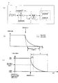
この様なファインダ内表示装置を実現するための技術としては、高いコントラストを得やすいPN(Polymer Network)液晶などを用いて、その光拡散性を利用した遮光型のスーパーインポーズ表示を行うものが知られている。しかし、この構成では、次の点が指摘される。すなわち、図1(b)に示す様に、PN液晶は、透過状態から非透過状態に移るまでの応答速度が低温下で低下する性質を有し、常温下の応答時間との間に例えばΔtだけ応答時間差が生じてしまう。カメラの合焦表示では、合焦した瞬間にその焦点検出領域を点灯させるのが好ましく、Δtの時間差、即ち反応スピードの低下は改善すべき点である。 As a technology for realizing such an in-finder display device, there is a technique for performing a light-shielded superimpose display using a light diffusion property using a PN (Polymer Network) liquid crystal or the like that easily obtains a high contrast. Are known. However, this configuration points out the following points. That is, as shown in FIG. 1B, the PN liquid crystal has a property that the response speed until the transition from the transmissive state to the non-transmissive state is reduced at a low temperature. Only a difference in response time will occur. In the focus display of the camera, it is preferable to turn on the focus detection area at the moment of focusing, and the time difference of Δt, that is, the decrease in reaction speed, should be improved.
こうした問題に対し、特許文献1に記載された方法は、ファインダ内表示部材として、LEDなどの発光表示素子とLCDなどの減光表示素子を併用している。この表示装置の一例では、カメラ周囲の温度と被写体の輝度を測定し、輝度が一定値以下の時は発光表示素子を用いて焦点検出領域の表示を行い、輝度が一定値以上かつ温度が一定値T1以上の場合は減光表示素子を用いて焦点検出領域の表示を行う。更に、輝度が一定値以上かつ温度が一定値T2以下の場合は発光表示素子と発光表示素子の一方或いは両方を用いて焦点検出領域の表示を行う。こうして、輝度や温度条件に応じて適した表示手段を選択することにより、選択された焦点検出領域を常に容易に認識できる様にしている。 With respect to such a problem, the method described in Patent Document 1 uses a light emitting display element such as an LED and a dimming display element such as an LCD together as a display member in the finder. In one example of this display device, the temperature around the camera and the brightness of the subject are measured, and when the brightness is below a certain value, the focus detection area is displayed using a light emitting display element, and the brightness is above a certain value and the temperature is constant. When the value is equal to or greater than T1, the focus detection area is displayed using a dimming display element. Further, when the luminance is a certain value or more and the temperature is a certain value T2 or less, the focus detection region is displayed using one or both of the light emitting display element and the light emitting display element. Thus, by selecting a display means suitable for the brightness and temperature conditions, the selected focus detection region can be always easily recognized.
しかしながら、特許文献1に記載された上記方法では、輝度や温度条件によってファインダ視野内の焦点検出領域の表示態様が変わってしまう。また、同じ焦点検出領域に対して発光表示素子と減光表示素子の2つの素子を必要とするため、コストがかかりがちとなる。 However, in the above method described in Patent Document 1, the display mode of the focus detection region in the finder field changes depending on the luminance and temperature conditions. In addition, since two elements, a light emitting display element and a dimming display element, are required for the same focus detection region, the cost tends to increase.
上記課題に鑑み、カメラなどの光学機器の本発明のファインダ内表示装置は、少なくとも、減光表示部と焦点検出手段と温度検出部と記憶部と演算部と制御部を有する。減光表示部は、透過光の拡散状態を変化させられる拡散型液晶を用いて、結像光学系からの光束の予定結像面上に結像された被写界像に重ね合わせて焦点検出領域をファインダ視野内に表示することが可能である。焦点検出手段は、選択された焦点検出領域における被写界像の焦点検出情報を取得可能である。温度検出部は、装置周りの温度を検出するための手段である。記憶部は、減光表示部の特性の情報を記憶するための手段である。演算部は、焦点検出手段が焦点検出動作を開始してから合焦するまでの時間を予め算出した時間である合焦予測時間の情報と温度検出部の温度の情報と記憶部の減光表示部の特性の情報に基づき、減光表示部を駆動開始すべき、合焦予測時間が経過する以前(経過した時点或いはそれに先立つ時点)の第1のタイミングを演算するための手段である。制御部は、演算部で演算された第1のタイミングで減光表示部を駆動開始する制御などを行う。 In view of the above problems, the in-finder display device of the present invention of an optical apparatus such as a camera has at least a dimming display unit, a focus detection unit, a temperature detection unit, a storage unit, a calculation unit, and a control unit. The dimming display unit uses a diffusion-type liquid crystal that can change the diffusion state of transmitted light, and detects the focus by superimposing it on the object field image formed on the planned image plane of the light beam from the imaging optical system. It is possible to display the region within the viewfinder field. The focus detection means can acquire focus detection information of the object scene image in the selected focus detection region. The temperature detector is a means for detecting the temperature around the apparatus. The storage unit is means for storing information on the characteristics of the dimming display unit. The calculation unit includes information on a predicted focus time, which is a pre-calculated time from when the focus detection unit starts the focus detection operation to focusing, information on the temperature of the temperature detection unit, and dimming display on the storage unit This is means for calculating the first timing before the predicted focus time elapses (at the time when it has passed or at the time prior to it), on which the dimming display unit should start driving, based on the information on the characteristics of the part. The control unit performs control to start driving the dimming display unit at the first timing calculated by the calculation unit.
本発明によれば、装置周りの温度条件に応じて拡散型液晶の駆動開始タイミングを制御することで、拡散型液晶の表示機能の温度依存性による影響を軽減したタイミングで合焦表示を行える様になる。例えば、低温時に、合焦時点で減光表示部の駆動を開始する場合よりも、早い適切な時点で焦点検出領域を表示することが可能になる。 According to the present invention, by controlling the drive start timing of the diffusive liquid crystal according to the temperature conditions around the apparatus, it is possible to perform in-focus display at a timing that reduces the influence of the temperature dependence of the display function of the diffusive liquid crystal. become. For example, it is possible to display the focus detection area at a suitable time earlier than when starting to drive the dimming display unit at the time of focusing at low temperatures.
以下、本発明の実施形態について説明する。本発明のファインダ内表示装置において重要なことは、次の点である。装置周りの温度を考慮して、焦点検出手段からの合焦予測時間と減光表示部の特性の情報に基づき、合焦予測時間が経過する以前のタイミングで、機能が温度依存性を持つ減光表示部の駆動を開始することである。例えば、常温よりかなり低い所定温度(例えば、マイナス5℃)より上の温度では、合焦予測時間が経過した時点で減光表示部の駆動を開始し、該所定温度以下では合焦予測時間に先立つ時点で減光表示部の駆動を開始する。こうした表示装置は、焦点検出領域での被写界像の焦点検出情報を取得可能で合焦予測時間を提供可能な焦点検出手段を備え、温度依存性を持つ減光表示部でファインダ視野内に焦点検出情報を表示する如何なる光学機器でも用いられる。 Hereinafter, embodiments of the present invention will be described. What is important in the in-finder display device of the present invention is the following point. Considering the temperature around the device, the function is temperature-dependent at the timing before the predicted focus time elapses based on the focus detection time from the focus detection means and the information on the characteristics of the dimming display. The driving of the optical display unit is started. For example, at a temperature higher than a predetermined temperature (for example, minus 5 ° C.) that is considerably lower than normal temperature, the dimming display unit starts to be driven when the predicted focus time elapses, and the predicted focus time is reached below the predetermined temperature. At the preceding time point, driving of the dimming display unit is started. Such a display device includes focus detection means capable of acquiring focus detection information of an object scene image in a focus detection region and providing a focus prediction time, and is a temperature-dependent dimming display unit in a finder field of view. Any optical device that displays focus detection information is used.
上記考え方に基づき、カメラなどの撮像装置等の光学機器で用いられる本発明のファインダ内表示装置の基本的な実施形態は、次の様な構成を有する。カメラなどの光学機器の本発明のファインダ内表示装置は、少なくとも、減光表示部と焦点検出手段と温度検出部と記憶部と演算部と制御部を有する。減光表示部は、透過光の拡散状態を変化させられる拡散型液晶(高分子分散液晶のPN液晶など)を用いて、結像光学系からの光束の予定結像面上に結像された被写界像に重ね合わせて焦点検出領域をファインダ視野内に表示できる。温度検出部は、装置周りの温度を検出する。記憶部は、減光表示部の特性の情報を記憶する。演算部は、焦点検出手段からの合焦予測時間の情報と温度検出部の温度の情報と記憶部の減光表示部の特性の情報に基づき、減光表示部を駆動開始すべき、合焦予測時間が経過する以前の第1のタイミングを演算する。制御部は、演算部で演算された第1のタイミングで減光表示部を駆動開始する制御などを行う。 Based on the above concept, a basic embodiment of the in-finder display device of the present invention used in an optical apparatus such as an imaging device such as a camera has the following configuration. The in-finder display device of the present invention of an optical apparatus such as a camera has at least a dimming display unit, a focus detection unit, a temperature detection unit, a storage unit, a calculation unit, and a control unit. The dimming display unit forms an image on the planned image plane of the light beam from the imaging optical system using diffusion type liquid crystal (such as PN liquid crystal of polymer dispersed liquid crystal) that can change the diffusion state of transmitted light. The focus detection area can be displayed in the viewfinder field superimposed on the object scene image. The temperature detection unit detects the temperature around the device. The storage unit stores information on characteristics of the dimming display unit. The arithmetic unit should start driving the dimming display unit based on the information on the predicted focus time from the focus detection unit, the temperature information on the temperature detection unit, and the information on the characteristics of the dimming display unit in the storage unit. A first timing before the predicted time elapses is calculated. The control unit performs control to start driving the dimming display unit at the first timing calculated by the calculation unit.
より具体的な実施形態として、以下の様な形態が可能である。
記憶部に記憶される減光表示部の特性の情報としては、所定温度(例えば、マイナス5℃)における減光表示部の特性(後述するta,tbなど)とすることができる。この場合、制御部は、温度が前記所定温度以下である場合、所定温度における減光表示部の特性に基づき演算された所定時間だけ合焦予測時間が経過するのに先立つ第1のタイミングで減光表示部を駆動開始する。温度が前記所定温度を超える場合は、合焦予測時間が経過した時点を第1のタイミングとすればよい。こうした形態では、第1のタイミングの調整は多少大まかになるが、記憶部の記憶負担が軽減できると共に演算部と制御部の演算ないし制御動作が簡略化できて、構成を簡易化できる。
As a more specific embodiment, the following forms are possible.
The information on the characteristics of the dimming display unit stored in the storage unit can be the characteristics (such as ta and tb described later) of the dimming display unit at a predetermined temperature (for example,
記憶部に記憶される減光表示部の特性の情報を、離散的な複数の温度における減光表示部の特性とすることもできる。この場合、制御部は、各温度と該各温度の次に低い温度との間において、該各温度における減光表示部の特性に基づき演算された所定時間だけ合焦予測時間が経過する以前の第1のタイミングで減光表示部を駆動開始する。こうした形態では、第1のタイミングの調整をより細かくできる。 Information on the characteristics of the dimming display unit stored in the storage unit may be the characteristics of the dimming display unit at a plurality of discrete temperatures. In this case, the control unit has a predetermined time calculated based on the characteristics of the dimming display unit at each temperature between each temperature and the next lower temperature before each predicted temperature. Driving of the dimming display unit is started at the first timing. In such a form, the first timing can be adjusted more finely.
記憶部に記憶される減光表示部の特性の情報を、温度を変数とする減光表示部の特性の関数とすることもできる(後述の実施例のPN液晶特性テーブルを参照)。この場合、制御部は、各温度において、該各温度における減光表示部の特性に基づき演算された所定時間だけ合焦予測時間が経過する以前の第1のタイミングで減光表示部を駆動開始する。こうした形態では、第1のタイミングの調整を更に細かくできる。 Information on the characteristics of the dimming display unit stored in the storage unit can also be a function of the characteristics of the dimming display unit using temperature as a variable (see the PN liquid crystal characteristic table of the embodiment described later). In this case, at each temperature, the control unit starts driving the dimming display unit at the first timing before the predicted focus time elapses for a predetermined time calculated based on the characteristics of the dimming display unit at each temperature. To do. In such a form, the first timing can be adjusted more finely.
また、記憶部に記憶される減光表示部の特性の情報を、各温度における、減光表示部の拡散型液晶の非透過状態が焦点検出領域の見えに支障の出ないレベルに達するまでに要する駆動開始時からの時間長さの情報とできる。この場合、演算部によって演算される第1のタイミングは、駆動開始時からの時間長さを合焦予測時間の長さから減算した時間だけ、演算部が合焦予測時間を取得した時から経過するタイミングとできる(後述の実施例参照)。 In addition, information on the characteristics of the dimming display unit stored in the storage unit is obtained until the non-transmission state of the diffusive liquid crystal of the dimming display unit at each temperature reaches a level that does not hinder the appearance of the focus detection region. This can be information on the length of time from the start of driving. In this case, the first timing calculated by the calculation unit has elapsed since the time when the calculation unit acquired the predicted focus time by the time obtained by subtracting the time length from the start of driving from the length of the predicted focus time. The timing can be set (see the examples described later).
また、本発明では減光表示部のみで表示を行うのも可能であるが、被写界光が少ない場合には、これのみの表示では暗くなる可能性があるので、発光表示部を用いると良い。この場合、次の様な形態にできる。装置は、更に、ファインダ視野内に表示された焦点検出領域に対して光を照射するためのLEDなどの発光表示部を有する。この場合、演算部は、減光表示部の駆動を続行させるか否かを判定する第2のタイミングをも演算すると良い(後述の実施例参照)。第2のタイミングは、合焦予測時間と温度と減光表示部の特性から、合焦予測時間の経過以後であって、第1のタイミングから経過して減光表示部の拡散型液晶が焦点検出領域表示の可能な非透過状態に達する時点前のタイミングである。そして、制御部は、減光表示部の駆動を続行させると判定した場合、第2のタイミング以後に発光表示部を駆動開始する制御も行う。 Further, in the present invention, it is possible to display only with the dimming display portion, but when there is little object light, there is a possibility that the display is dark only with this display, so if the light emitting display portion is used, good. In this case, the following configuration can be adopted. The apparatus further includes a light emitting display such as an LED for irradiating light to a focus detection area displayed in the viewfinder field. In this case, the calculation unit may also calculate a second timing for determining whether or not to continue driving the dimming display unit (see an example described later). The second timing is after the elapse of the predicted focus time from the focus predicted time, temperature, and the characteristics of the dimming display unit, and after the first timing, the diffusion type liquid crystal of the dimming display unit is focused. This is the timing before reaching the non-transparent state in which the detection area can be displayed. And when it determines with continuing a drive of a dimming display part, a control part also performs control which starts a light emission display part after a 2nd timing.
減光表示部の駆動を続行させるか否かを判定する第2のタイミングは、演算部が合焦予測時間を取得した時から合焦予測時間だけ経過したタイミングとできる。制御部は、第2のタイミングから所定時間経過後に発光表示部を駆動開始する様にできる。また、上記構成で、演算部が焦点検出手段から合焦予測時間の情報を取得した時から第1のタイミングまでの時間や第2のタイミングまでの時間や発光表示部を駆動開始するタイミングを計測するタイマーを備えることができる(後述の実施例参照)。 The second timing for determining whether or not to continue driving the dimming display unit can be a timing when the predicted focus time has elapsed since the calculation unit acquired the predicted focus time. The control unit can start driving the light emitting display unit after a predetermined time has elapsed from the second timing. Further, with the above configuration, the time from the time when the calculation unit acquires information on the predicted focus time from the focus detection unit to the first timing, the time until the second timing, and the timing to start driving the light emitting display unit are measured. (See examples below).
以下、本発明の実施例を図を用いて説明する。
本実施例のカメラ10は、図1(a)のブロック図に示す構成を有している。カメラのファインダ内表示器11は、PN液晶を用いた減光表示部12、LEDを用いた発光表示部13を備える。ファインダ内表示器11では、例えば図2(a)に示す様に、PN液晶層を挟む透明電極のセグメントで形成される焦点検出枠1〜5のPN液晶領域を非透過にすることで、ファインダ視野内で焦点検出領域の表示を行う。そして、LEDの発光表示部13からの照射光により焦点検出枠1〜5を例えば赤く照射することで、利用者にこの領域において合焦したことを知らせる。PN液晶では、非透過にするには、上記透明電極への電圧を非印加状態とし、透過にするには、上記透明電極への電圧を印加状態とする。焦点検出枠による表示形態は、図2(a)に示す様なものに限られず、場合に応じて適宜設計すればよい。例えば、1つの焦点検出枠で焦点検出領域を表してもよい。枠の形状も四角形以外に、丸形状、鉤形状などであってもよい。
Embodiments of the present invention will be described below with reference to the drawings.
The
本実施例のカメラは、更に、焦点検出手段であるAFシステム14を有し、合焦予測時間を演算部17に渡すことができる。温度計は温度検出部15の役割を果たし、カメラの周囲温度を検出して演算部17に温度情報を通知することができる。カメラの記憶部であるメモリは、例えば、使用するPN液晶の温度特性の情報を保持したPN液晶特性テーブル16を持っている。具体的には、以下の3点の特性を保持している。
(1)図1(c)に示す様にPN液晶が全透過状態1から、駆動を開始して見えに支障が出ない透過率の状態2に達するまでの時間ta。
(2)PN液晶が、全透過状態1から、駆動を開始して非透過、即ち焦点検出領域表示の可能になる非透過の状態3に達するまでの時間tb。
(3)温度Tによるta,tbの変化量。
以上3点の特性(例えば、温度Tを変数とするta,tbの関数)により、演算部17は検出温度における時間ta,tbを算出することができる。
The camera of the present embodiment further includes an AF system 14 that is a focus detection unit, and can pass the predicted focus time to the calculation unit 17. The thermometer serves as the temperature detection unit 15 and can detect the ambient temperature of the camera and notify the calculation unit 17 of the temperature information. A memory serving as a storage unit of the camera has, for example, a PN liquid crystal characteristic table 16 holding information on temperature characteristics of the PN liquid crystal to be used. Specifically, the following three characteristics are retained.
(1) As shown in FIG. 1C, the time ta required for the PN liquid crystal to reach the
(2) Time tb from the total transmission state 1 until the PN liquid crystal reaches the non-transmission state 3 in which driving is started and non-transmission, that is, the focus detection area display is possible.
(3) Changes in ta and tb due to temperature T.
The computing unit 17 can calculate the times ta and tb at the detected temperature based on the above three characteristics (for example, a function of ta and tb with the temperature T as a variable).
この様に、カメラのCPUの演算部17は、AFシステム14より合焦予測時間を取得し、温度検出部15から周囲温度を取得する。そして、合焦予測時間、及びテーブル16と温度検出部15から夫々取得した情報で算出した周囲温度に対応したPN液晶の駆動特性に係る時間ta,tbに基づき、減光表示部12と発光表示部13の駆動開始タイミングをタイマー18にセットする。カメラのCPUでは、また、ファインダ内表示器11の駆動用ICであるLCD駆動回路によって制御部19が構成され、タイマー18にセットされた時間に基づき、ファインダ内表示器11のPN液晶やLEDを駆動制御する。常温に比較的近い通常の温度下では、各情報を取得した時から合焦予測時間が経過した時点(第1のタイミング)で、制御部19はPN液晶の駆動を開始する。これに対して、常温よりかなり低い所定温度(例えば、マイナス5℃)以下では、上記周囲温度に対応したPN液晶の駆動特性を考慮して、合焦予測時間が経過するのに先立つ時点(第1のタイミング)で制御部19はPN液晶の駆動を開始する。どの程度先立たせるかは、温度に応じて決めてもよいが、前述した様に、所定温度以下では、固定の所定時間先立たせるという制御も可能である。
As described above, the calculation unit 17 of the CPU of the camera acquires the predicted focus time from the AF system 14 and acquires the ambient temperature from the temperature detection unit 15. Then, based on the predicted focus time and the time ta, tb related to the driving characteristics of the PN liquid crystal corresponding to the ambient temperature calculated from the information acquired from the table 16 and the temperature detection unit 15 respectively, the dimming display unit 12 and the light emission display The drive start timing of the unit 13 is set in the timer 18. In the CPU of the camera, the
合焦予測時間は、合焦に至るまでに要すると推測される時間である。より具体的には、撮影レンズを非合焦状態から合焦状態へ向けて移動させる際に、並行して連続的に焦点調節情報を取得し、取得した複数の焦点調節情報を基に合焦に至るまでの時間を算出することで予測するものである。例えば、焦点検出手段のセンサ部の合焦時の状態と合焦予測時間取得時の状態との差、合焦予測時間取得時の状態の変化率(時間微分係数)などから算出することができる。合焦予測時間が取得できるのであれば、焦点検出手段の方式は問わない。所謂位相差検出方式、撮像素子の出力を用いたコントラスト検出方式、アクティブタイプの焦点調節方式(特開昭63−85617号公報参照)などを用いることができる。 The predicted focus time is a time estimated to be required until focusing is achieved. More specifically, when the photographic lens is moved from the out-of-focus state to the in-focus state, the focus adjustment information is continuously acquired in parallel, and the focus is based on the acquired plurality of focus adjustment information. This is predicted by calculating the time until the time. For example, it can be calculated from the difference between the state at the time of focusing of the sensor unit of the focus detection means and the state at the time of acquiring the predicted focus time, the change rate (time differential coefficient) of the state at the time of acquiring the predicted focus time, and the like. . As long as the predicted focus time can be acquired, the method of the focus detection means is not limited. A so-called phase difference detection method, a contrast detection method using the output of the image sensor, an active type focus adjustment method (see JP-A-63-85617), and the like can be used.
上記構成を含むカメラの概略的な全体構成を図4を用いて説明する。図4において、101はCPU(中央演算処理装置)であり、本カメラの動作はこのCPU101により制御される。105は撮影レンズであり、撮影被写界光を撮像素子であるCCD106上に結像させる。同図に描かれた撮影レンズ105は、便宜的に1枚のレンズ105aで表現しているが、実際には複数のレンズから成り立っている。128は、撮影レンズ105のCCD106結像面と等価の結像面に置かれた焦点検出板(ピント板)であり、被写界像は主ミラー126で反射されピント板128に1次結像する。撮影者は、この被写界像をペンタプリズム127、接眼レンズ121を通じて見ることができる。この様に、本カメラでは、いわゆるTTL方式の光学ファインダ構成のファインダ内表示装置となっている。一方、主ミラー126は半透過ミラーであり、透過した一部の光束はサブミラー122を通じて焦点検出手段である焦点検出ユニット119(AFシステム14はこれを含む)に導かれ、周知の位相差検出方式の焦点検出動作が行われる。この焦点検出動作の結果等に基づき、CPU101は、レンズ駆動用モータなどを含むレンズ駆動部131を介して撮影レンズ105の位置を制御する。。
A schematic overall configuration of the camera including the above configuration will be described with reference to FIG. In FIG. 4,
また、130はシリコンフォトダイオードからなる測光センサである。測光手段である測光センサ130は、ピント板128に結像した被写界像を測光レンズ129で測光センサ130のチップ上に2次結像させて被写界の輝度分布を検出する。ここで、測光センサ130のチップ部は、適当数の測光領域に分割されており、各領域に対応した被写界の輝度検出が可能である。更に、本実施例では、測光センサ130の回路部は、温度計が実装してあり、環境下におけるカメラの内部温度を検出可能な温度検出手段(温度検出部15に対応)にもなっている。
112は、ピント板128の近傍に配置された高分子分散液晶パネルからなる表示手段(減光表示部12に対応)であり、光学ファインダを覗いているカメラの撮影者に上記焦点検出動作の状態表示を知らせる。PN液晶パネル112は、通常、透過(透明)状態におかれる。そして、焦点検出ユニット119の焦点検出の結果、合焦に至ったと判断された焦点検出領域に対応したPN液晶パネル112上の表示部のみが非透過(非透明)となって、撮影者にピントの合った被写界位置を知らせることが可能となっている。また、このとき、PN液晶パネル112上の表示部に対して光を照射する発光手段であるLED123(発光表示部13に対応)が設けられている。このLED照射光は導光プリズム124を通じてPN液晶パネル112へ照射される。すると、PN液晶表示パネル112上の非透過となっている焦点検出領域表示部のみが、ファインダの観察者に光って見えることとなる。
撮影者がレリーズスイッチを押すと、主ミラー126は撮影レンズ105の光路外に退避する。一方、撮影レンズ105によって集光された被写界光はフォーカルプレーンシャッタ133でその光量制御がなされ、CCD(撮像素子)106によって被写界像として光電変換処理される。その後、撮影済み画像として記録メディアに記録されるとともに、TFT外部表示部113に撮影画像の表示がなされる。
When the photographer presses the release switch, the main mirror 126 is retracted out of the optical path of the photographing
図2(b)のフローチャートを用いて、本実施例の動作を説明する。ステップ201で、カメラのCPUは、焦点検出手段のAFシステム14によるAFの動作が開始したかを監視し、開始されるとステップ202でタイマー18の時間tを0に初期化する。次に、ステップ203では、カメラのCPU内の演算部17はAFシステム14から合焦予測時間t2を取得する。次に、ステップ204で、周囲温度Tを温度検出部15より取得し、温度Tに対応した、減光表示部12のPN液晶の状態1から状態2へ遷移する時間ta及び状態1から状態3へ遷移する時間tbをメモリ内のPN液晶特性テーブル16より取得する。そして、t1=t2-taによりPN液晶の駆動開始時間(第1のタイミング)t1を算出し、t3=t2+tb-taにより発光表示部13のLEDを点灯させる時間t3を算出し、ステップ205へ進む。ステップ205では、カメラのCPUはタイマー18の時間tがt1になるまで待機し、t=t1となればステップ206へ進む。ステップ206で、制御部19はPN液晶の駆動を開始する。ステップ207では、カメラのCPUはタイマー18の時間tがt2になるまで待機し、t=t2(第2のタイミング)になったらステップ208へ進む。
The operation of the present embodiment will be described with reference to the flowchart of FIG. In
ステップ208では、制御部19は合焦したか否かの判定を行う。選択した焦点検出領域において合焦したと判定されれば、そのままPN液晶の非透過状態への駆動動作を続ける。ステップ209で、カメラのCPUはタイマー時間tがt3になるまで待機し、tがt3になったらステップ210へ進む。ステップ210で、制御部19はLEDを点灯させ、焦点検出領域をPN液晶の非透過とLED点灯により表示し、カメラの使用者に合焦したことを知らせる。
In
ステップ208において、合焦していないと判定されれば、制御部19はステップ211でPN液晶を状態1へ遷移させるよう制御動作を行い、ステップ201へ戻る。以上が本実施例による動作の説明である。なお、選択可能な焦点検出枠の個数や位置は上記実施例の例に限定されない。また、PN液晶の状態1から状態3への駆動を続行させるかを判定する時間は、LEDを駆動させる時間t3の一定時間前となる時間或いは時間t3と同じ時間であればよい。また、本実施例では、減光表示部としてPN液晶を用い、発光表示部としてLEDを用いたが、同様の特性を示す部材でもよい。
If it is determined in
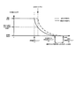
上記実施例を実施した時に得られる効果を図3を用いて説明する。PN液晶の状態1から状態3への駆動を合焦判定と同タイミングで行う従来の方法(破線で示す)と比較して、その一定時間前より駆動を開始させることにより、Δt3だけ早い時間でカメラの使用者に合焦を知らせることができる。また、PN液晶の或る透過率の状態2の時点で状態3への駆動を継続するかを判定することにより、合焦しなかった場合には焦点検出領域の表示を回避することができる。
The effect obtained when the above embodiment is implemented will be described with reference to FIG. Compared with the conventional method (shown by a broken line) in which the driving of the PN liquid crystal from the state 1 to the state 3 is performed at the same timing as the in-focus determination, the driving is started a certain time earlier by Δt3. The camera user can be notified of the in-focus state. Further, by determining whether or not to continue driving to the state 3 at the time of the
以上により、温度条件によらずファインダ視野内の表示エリアの表示方法が変化せず、低温度下においても、合焦後の表示のタイムラグも短くできる。この様に、本実施例によれば、焦点検出領域の表示部材(PN液晶など)の応答が悪い低温度の環境下でも、可能な限り早い時間で焦点検出領域の表示を可能にするファインダ内表示装置を実現できる。 As described above, the display method of the display area in the finder field of view does not change regardless of the temperature condition, and the time lag of display after focusing can be shortened even at low temperatures. Thus, according to the present embodiment, the focus detection area can be displayed in the finder as early as possible even in a low temperature environment where the response of the display member (PN liquid crystal or the like) of the focus detection area is poor. A display device can be realized.
1〜5 焦点検出枠(焦点検出領域)
12、112 減光表示部
13、123 発光表示部
14、119 AFシステム(焦点検出手段)
15 温度検出部
16 PN液晶特性テーブル(記憶部)
17 演算部
19 制御部
101 CPU(演算部、制御部)
105 撮影レンズ(結像光学系)
130 測光センサ(温度検出部)
1-5 Focus detection frame (focus detection area)
12, 112
15 Temperature detection unit 16 PN liquid crystal characteristic table (storage unit)
17
105 Photography lens (imaging optical system)
130 Photometric sensor (temperature detector)
Claims (8)
選択された焦点検出領域における被写界像の焦点検出情報を取得可能な焦点検出手段と、
装置周りの温度を検出するための温度検出部と、
前記減光表示部の特性の情報を記憶するための記憶部と、
前記焦点検出手段が焦点検出動作を開始してから合焦するまでの時間を予め算出した時間である合焦予測時間の情報と前記温度検出部からの温度の情報と前記記憶部に記憶された減光表示部の特性の情報に基づいて、前記減光表示部の駆動を開始すべき、前記合焦予測時間が経過する以前の第1のタイミングを演算するための演算部と、
前記演算部で演算された第1のタイミングで前記減光表示部を駆動開始するための制御部と、
を有することを特徴とする光学機器のファインダ内表示装置。 Using a diffusive liquid crystal that can change the diffusion state of transmitted light, the focus detection area is finder overlapped with the object field image formed on the planned image plane of the light beam from the imaging optical system. A dimming display that can be displayed within the field of view;
Focus detection means capable of acquiring focus detection information of the object scene image in the selected focus detection region;
A temperature detection unit for detecting the temperature around the device;
A storage unit for storing information on characteristics of the dimming display unit;
Information on the predicted focus time, which is a time calculated in advance from the start of the focus detection operation by the focus detection unit to the in-focus state, the temperature information from the temperature detection unit, and the storage unit Based on the information on the characteristics of the dimming display unit, the calculation unit for calculating the first timing before the predicted focus time elapses, which should start driving the dimming display unit;
A control unit for starting driving the dimming display unit at a first timing calculated by the calculation unit;
An in-finder display device for an optical apparatus, comprising:
前記制御部は、前記温度が前記所定温度以下である場合、前記所定温度における減光表示部の特性に基づき演算された所定時間だけ前記合焦予測時間が経過するのに先立つ第1のタイミングで前記減光表示部を駆動開始することを特徴とする請求項1に記載の光学機器のファインダ内表示装置。 Information on the characteristics of the dimming display unit stored in the storage unit is the characteristics of the dimming display unit at a predetermined temperature,
When the temperature is equal to or lower than the predetermined temperature, the control unit has a first timing prior to elapse of the predicted focus time by a predetermined time calculated based on the characteristics of the dimming display unit at the predetermined temperature. The in-finder display device for an optical apparatus according to claim 1, wherein driving of the dimming display unit is started.
前記制御部は、各温度と該各温度の次に低い温度との間において、該各温度における減光表示部の特性に基づき演算された所定時間だけ前記合焦予測時間が経過する以前の第1のタイミングで前記減光表示部を駆動開始することを特徴とする請求項1に記載の光学機器のファインダ内表示装置。 Information on the characteristics of the dimming display unit stored in the storage unit is the characteristics of the dimming display unit at a plurality of discrete temperatures,
The control unit is configured such that the control unit performs a predetermined time calculated based on the characteristics of the dimming display unit at each temperature between each temperature and the next lower temperature before the predicted focus time elapses. The in-finder display device for an optical apparatus according to claim 1, wherein the dimming display unit starts to be driven at a timing of 1.
前記制御部は、各温度において、該各温度における減光表示部の特性に基づき演算された所定時間だけ前記合焦予測時間が経過する以前の第1のタイミングで前記減光表示部を駆動開始することを特徴とする請求項1に記載の光学機器のファインダ内表示装置。 Information on the characteristics of the dimming display unit stored in the storage unit is a function of the characteristics of the dimming display unit with temperature as a variable,
The control unit starts driving the dimming display unit at a first timing before the predicted focus time elapses for a predetermined time calculated based on the characteristics of the dimming display unit at each temperature. The in-finder display device for an optical apparatus according to claim 1.
前記演算部によって演算される第1のタイミングは、前記駆動開始時からの時間長さを前記合焦予測時間の長さから減算した時間だけ、前記演算部が前記合焦予測時間を取得した時から経過するタイミングであることを特徴とする請求項1から4の何れか1項に記載の光学機器のファインダ内表示装置。 Information on the characteristics of the dimming display unit stored in the storage unit until the non-transmission state of the diffusive liquid crystal of the dimming display unit at each temperature reaches a level that does not hinder the appearance of the focus detection region. Information on the length of time required from the start of driving,
The first timing calculated by the calculation unit is the time when the calculation unit obtains the predicted focus time by a time obtained by subtracting the time length from the start of driving from the length of the predicted focus time. The in-finder display device for an optical apparatus according to any one of claims 1 to 4, wherein the timing elapses from the time point.
前記演算部は、前記合焦予測時間の情報と前記温度の情報と前記減光表示部の特性の情報から、前記合焦予測時間の経過以後であって、前記第1のタイミングから経過して前記減光表示部の拡散型液晶が焦点検出領域表示の可能な非透過状態に達する時点前のタイミングの、前記減光表示部の駆動を続行させるか否かを判定する第2のタイミングを演算し、
前記制御部は、前記減光表示部の駆動を続行させると判定した場合、前記第2のタイミング以後に前記発光表示部を駆動開始することを特徴とする請求項1から5の何れか1項に記載の光学機器のファインダ内表示装置。 It has a light emission display for irradiating light to the focus detection area displayed in the viewfinder field,
The calculation unit, after the elapse of the predicted focus time, has elapsed from the first timing, based on the predicted focus time information, the temperature information, and the dimming display unit characteristic information. A second timing for determining whether or not to continue driving the dimming display unit is calculated before the time point when the diffusion type liquid crystal of the dimming display unit reaches a non-transmissive state in which focus detection area display is possible. And
The said control part starts the said light emission display part after the said 2nd timing, when it determines with continuing the drive of the said light reduction display part, The any one of Claim 1 to 5 characterized by the above-mentioned. A display device in the viewfinder of the optical apparatus described in 1.
Priority Applications (1)
| Application Number | Priority Date | Filing Date | Title |
|---|---|---|---|
| JP2009102985A JP5552257B2 (en) | 2009-04-21 | 2009-04-21 | Display device in viewfinder of optical equipment |
Applications Claiming Priority (1)
| Application Number | Priority Date | Filing Date | Title |
|---|---|---|---|
| JP2009102985A JP5552257B2 (en) | 2009-04-21 | 2009-04-21 | Display device in viewfinder of optical equipment |
Publications (3)
| Publication Number | Publication Date |
|---|---|
| JP2010256410A JP2010256410A (en) | 2010-11-11 |
| JP2010256410A5 JP2010256410A5 (en) | 2012-06-07 |
| JP5552257B2 true JP5552257B2 (en) | 2014-07-16 |
Family
ID=43317436
Family Applications (1)
| Application Number | Title | Priority Date | Filing Date |
|---|---|---|---|
| JP2009102985A Expired - Fee Related JP5552257B2 (en) | 2009-04-21 | 2009-04-21 | Display device in viewfinder of optical equipment |
Country Status (1)
| Country | Link |
|---|---|
| JP (1) | JP5552257B2 (en) |
Families Citing this family (1)
| Publication number | Priority date | Publication date | Assignee | Title |
|---|---|---|---|---|
| JP5725988B2 (en) * | 2011-06-13 | 2015-05-27 | キヤノン株式会社 | Imaging apparatus and control method thereof |
Family Cites Families (1)
| Publication number | Priority date | Publication date | Assignee | Title |
|---|---|---|---|---|
| JP4352550B2 (en) * | 2000-01-18 | 2009-10-28 | 株式会社ニコン | Liquid crystal display illumination device and camera equipped with the same |
-
2009
- 2009-04-21 JP JP2009102985A patent/JP5552257B2/en not_active Expired - Fee Related
Also Published As
| Publication number | Publication date |
|---|---|
| JP2010256410A (en) | 2010-11-11 |
Similar Documents
| Publication | Publication Date | Title |
|---|---|---|
| JP4142205B2 (en) | Electronic still camera | |
| TWI355187B (en) | Imaging apparatus | |
| US8559808B2 (en) | Imaging apparatus | |
| JP5725988B2 (en) | Imaging apparatus and control method thereof | |
| JP6614853B2 (en) | Imaging device, control method thereof, and control program | |
| JP2002152558A (en) | Camera | |
| JP2008177917A (en) | Solid-state imaging device | |
| US9386227B2 (en) | Finder apparatus for a camera, finder display controlling method, and storage medium | |
| CN102023458B (en) | Imaging apparatus | |
| JP5552257B2 (en) | Display device in viewfinder of optical equipment | |
| US20160100105A1 (en) | Interchangeable lens, image capturing apparatus and storage medium storing control program | |
| JP5333888B2 (en) | Imaging apparatus and program thereof | |
| JP2009044382A (en) | Camera display device | |
| JP2010282107A (en) | Imaging apparatus and control method thereof | |
| JP2016080742A (en) | Imaging device | |
| JP2006146081A (en) | Ranging device and imaging device | |
| JP2013066051A (en) | Photographing device | |
| JP4928236B2 (en) | Imaging apparatus and imaging system | |
| JP2010134112A (en) | Light generator and photographing apparatus | |
| JP2010243765A (en) | Display device and display device for optical instrument | |
| JP2016086208A (en) | Imaging device | |
| JP2014191184A (en) | Imaging device, imaging device control method and control program | |
| JP2013042446A (en) | Imaging apparatus | |
| JP2015232665A (en) | Imaging device | |
| JP2000075392A (en) | camera |
Legal Events
| Date | Code | Title | Description |
|---|---|---|---|
| A521 | Written amendment |
Free format text: JAPANESE INTERMEDIATE CODE: A523 Effective date: 20120420 |
|
| A621 | Written request for application examination |
Free format text: JAPANESE INTERMEDIATE CODE: A621 Effective date: 20120420 |
|
| A977 | Report on retrieval |
Free format text: JAPANESE INTERMEDIATE CODE: A971007 Effective date: 20130822 |
|
| A131 | Notification of reasons for refusal |
Free format text: JAPANESE INTERMEDIATE CODE: A131 Effective date: 20130827 |
|
| A521 | Written amendment |
Free format text: JAPANESE INTERMEDIATE CODE: A523 Effective date: 20131015 |
|
| TRDD | Decision of grant or rejection written | ||
| A01 | Written decision to grant a patent or to grant a registration (utility model) |
Free format text: JAPANESE INTERMEDIATE CODE: A01 Effective date: 20140424 |
|
| A61 | First payment of annual fees (during grant procedure) |
Free format text: JAPANESE INTERMEDIATE CODE: A61 Effective date: 20140526 |
|
| LAPS | Cancellation because of no payment of annual fees |