JP5551937B2 - High dynamic range camera with multiple sensors and image generation method - Google Patents
High dynamic range camera with multiple sensors and image generation method Download PDFInfo
- Publication number
- JP5551937B2 JP5551937B2 JP2009541566A JP2009541566A JP5551937B2 JP 5551937 B2 JP5551937 B2 JP 5551937B2 JP 2009541566 A JP2009541566 A JP 2009541566A JP 2009541566 A JP2009541566 A JP 2009541566A JP 5551937 B2 JP5551937 B2 JP 5551937B2
- Authority
- JP
- Japan
- Prior art keywords
- image sensor
- dynamic range
- image
- sensor array
- high dynamic
- Prior art date
- Legal status (The legal status is an assumption and is not a legal conclusion. Google has not performed a legal analysis and makes no representation as to the accuracy of the status listed.)
- Active
Links
Images


Classifications
-
- H—ELECTRICITY
- H04—ELECTRIC COMMUNICATION TECHNIQUE
- H04N—PICTORIAL COMMUNICATION, e.g. TELEVISION
- H04N23/00—Cameras or camera modules comprising electronic image sensors; Control thereof
-
- H—ELECTRICITY
- H04—ELECTRIC COMMUNICATION TECHNIQUE
- H04N—PICTORIAL COMMUNICATION, e.g. TELEVISION
- H04N23/00—Cameras or camera modules comprising electronic image sensors; Control thereof
- H04N23/50—Constructional details
- H04N23/54—Mounting of pick-up tubes, electronic image sensors, deviation or focusing coils
-
- H—ELECTRICITY
- H04—ELECTRIC COMMUNICATION TECHNIQUE
- H04N—PICTORIAL COMMUNICATION, e.g. TELEVISION
- H04N23/00—Cameras or camera modules comprising electronic image sensors; Control thereof
- H04N23/70—Circuitry for compensating brightness variation in the scene
- H04N23/741—Circuitry for compensating brightness variation in the scene by increasing the dynamic range of the image compared to the dynamic range of the electronic image sensors
-
- H—ELECTRICITY
- H04—ELECTRIC COMMUNICATION TECHNIQUE
- H04N—PICTORIAL COMMUNICATION, e.g. TELEVISION
- H04N23/00—Cameras or camera modules comprising electronic image sensors; Control thereof
- H04N23/45—Cameras or camera modules comprising electronic image sensors; Control thereof for generating image signals from two or more image sensors being of different type or operating in different modes, e.g. with a CMOS sensor for moving images in combination with a charge-coupled device [CCD] for still images
-
- H—ELECTRICITY
- H04—ELECTRIC COMMUNICATION TECHNIQUE
- H04N—PICTORIAL COMMUNICATION, e.g. TELEVISION
- H04N23/00—Cameras or camera modules comprising electronic image sensors; Control thereof
- H04N23/70—Circuitry for compensating brightness variation in the scene
-
- H—ELECTRICITY
- H04—ELECTRIC COMMUNICATION TECHNIQUE
- H04N—PICTORIAL COMMUNICATION, e.g. TELEVISION
- H04N23/00—Cameras or camera modules comprising electronic image sensors; Control thereof
- H04N23/95—Computational photography systems, e.g. light-field imaging systems
- H04N23/951—Computational photography systems, e.g. light-field imaging systems by using two or more images to influence resolution, frame rate or aspect ratio
-
- H—ELECTRICITY
- H04—ELECTRIC COMMUNICATION TECHNIQUE
- H04N—PICTORIAL COMMUNICATION, e.g. TELEVISION
- H04N25/00—Circuitry of solid-state image sensors [SSIS]; Control thereof
- H04N25/50—Control of the SSIS exposure
- H04N25/57—Control of the dynamic range
-
- H—ELECTRICITY
- H04—ELECTRIC COMMUNICATION TECHNIQUE
- H04N—PICTORIAL COMMUNICATION, e.g. TELEVISION
- H04N23/00—Cameras or camera modules comprising electronic image sensors; Control thereof
- H04N23/60—Control of cameras or camera modules
- H04N23/63—Control of cameras or camera modules by using electronic viewfinders
Description
本発明は、電子カメラ、特に多重露出を把捉するための方法と電子カメラ装置に関する。本発明は、ダイナミックレンジ画像の把捉に応用される。 The present invention relates to an electronic camera, and more particularly to a method and an electronic camera apparatus for capturing multiple exposures. The present invention is applied to grasping a dynamic range image.
現実の世界の光景は、最も明るいハイライトと、最も暗い影とのコントラスト比が50000:1に達することがある。従来の多くの画像フォーマットと、画像表示装置(例:デジタルプロジェクタ、コンピュータモニタなど)は、数百対1のコントラスト比しか再現できない。このようなファイルフォーマットによって、各色8ビット数を用いて画素の輝度値を規定することは珍しくない。 Real world scenes may have a contrast ratio of 50000: 1 between the brightest highlight and the darkest shadow. Many conventional image formats and image display devices (eg, digital projectors, computer monitors, etc.) can only reproduce a contrast ratio of several hundred to one. With such a file format, it is not uncommon to define the luminance value of a pixel using an 8-bit number for each color.
高ダイナミックレンジ(HDR)画像フォーマットは、慣用的な8ビット画像フォーマットのコントラスト比よりも、著しく大きなコントラスト比を記録できる。たとえば幾つかの高ダイナミックレンジフォーマットは、種々のレベルの輝度を表すための各色16ビットまたは32ビット使用する。 The high dynamic range (HDR) image format can record a significantly higher contrast ratio than the contrast ratio of the conventional 8-bit image format. For example, some high dynamic range formats use 16 or 32 bits of each color to represent various levels of brightness.
高ダイナミックレンジ(HDR)画像を得る1つの方法は、慣用的な撮像装置を用いて種々異なる露出レベルの多重画像を得ることである。この技術について論じた例を挙げると、非特許文献1があり、参照によって本願に編入される。 One way to obtain a high dynamic range (HDR) image is to obtain multiple images with different exposure levels using conventional imaging devices. An example that discusses this technique is Non-Patent Document 1, which is incorporated herein by reference.
多重画像の問題点は、他の画像と位置合わせしなければならないことである。そのためにほとんどの場合に三脚を使用することが必要となる。更に、高ダイナミックレンジ画像に組合わせるのに適した多重画像を得るようにカメラを設定することは、各々の画像に使用すべき露出を適切に組合わせることに関して相当な知識を求められる。 The problem with multiple images is that they must be aligned with other images. This requires the use of a tripod in most cases. Furthermore, setting the camera to obtain multiple images suitable for combination with high dynamic range images requires considerable knowledge regarding the proper combination of exposures to be used for each image.
高ダイナミックレンジ画像は、主流になりつつあり、容易に高ダイナミックレンジ画像を得るための方法と装置に対するニーズがある。 High dynamic range images are becoming mainstream and there is a need for a method and apparatus for easily obtaining high dynamic range images.
本発明は、電子カメラで多重露出を得るための方法と装置を提供する。この方法と装置は、高ダイナミックレンジ画像を生成するために組合わせできる画像を得るために応用できる。本発明の幾つかの実施例に従う装置は、多重画像センサを有する電子カメラを含んでよい。 The present invention provides a method and apparatus for obtaining multiple exposures with an electronic camera. This method and apparatus can be applied to obtain an image that can be combined to produce a high dynamic range image. An apparatus according to some embodiments of the invention may include an electronic camera having multiple image sensors.
本発明の1つの実施形態は、2個以上の画像センサアレイを含む電子カメラを提供する。画像センサアレイのうち少なくとも1個は、高ダイナミックレンジを有する。カメラはまた、光を選択的に2個以上の画像センサアレイに到達できるようにするシャッタと、画像センサアレイから選択的に画素データを読出すための読出回路と、シャッタと読出回路を制御するように構成されたコントローラとを含む。コントローラは、プロセッサと、コンピュータ可読コードを組入れたメモリとを含む。コンピュータ可読コードは、プロセッサによって実行されると、コントローラに画像把捉期間中にシャッタを開かせて、2個以上の画像センサアレイが画素データを把捉できるようにし、かつ2個以上の画像センサアレイから画素データを読出可能にする。 One embodiment of the present invention provides an electronic camera that includes two or more image sensor arrays. At least one of the image sensor arrays has a high dynamic range. The camera also controls a shutter that allows light to selectively reach two or more image sensor arrays, a readout circuit for selectively reading pixel data from the image sensor array, and controls the shutter and readout circuit. And a controller configured as described above. The controller includes a processor and memory incorporating computer readable code. The computer readable code, when executed by the processor, causes the controller to open the shutter during the image capture period to allow the two or more image sensor arrays to capture the pixel data and from the two or more image sensor arrays. Pixel data can be read out.
本発明の他の実施形態は、少なくとも1個が高ダイナミックレンジを有する2個以上の画像センサアレイを含む電子カメラによって、高ダイナミックレンジ画像を生成するための方法を提供する。この方法は、画像把捉期間中に光が選択的に2個以上の画像センサアレイに到達できるようにし、画像把捉期間中に2個以上の画像センサアレイによって把捉された画素データを読出し、2個以上の画像センサアレイから読出した画素データを組合わせて高ダイナミックレンジ画像データを生成することを含む。 Another embodiment of the present invention provides a method for generating a high dynamic range image with an electronic camera that includes two or more image sensor arrays, at least one of which has a high dynamic range. This method allows light to selectively reach two or more image sensor arrays during the image capture period, reads out pixel data captured by two or more image sensor arrays during the image capture period, This includes generating high dynamic range image data by combining pixel data read from the image sensor array.
以下に、本発明のその他の実施形態と具体的な実施例の特徴を説明する。
以下の説明では、本発明をより完全に理解できるように具体的な詳細を記す。しかし本発明は、これらの詳細なしに実施されてよい。他方で、本発明を不必要に曖昧にするのを避けるために、よく知られている要素は、図示または詳細に説明しなかった。従って、明細書と図面は制限するものではなく、例示することを意図すると見なされなければならない。
The features of other embodiments and specific examples of the present invention will be described below.
In the following description, specific details are set forth in order to provide a more thorough understanding of the present invention. However, the invention may be practiced without these details. On the other hand, well-known elements have not been shown or described in detail to avoid unnecessarily obscuring the present invention. The specification and drawings are accordingly to be regarded as illustrative rather than restrictive.
本発明の1つの実施形態は、単一の画像の多重露出を把捉するように構成された電子カメラを提供する。多重露出は、高ダイナミックレンジ(HDR)を生成するために使用されてよい。多重露出に由来するデータを組合わせて高ダイナミックレンジ画像を生成する方法は、当業界で知られている。そのような方法を論じた例を挙げると、参照によって本願に編入される非特許文献2、そして上述した非特許文献1がある。 One embodiment of the present invention provides an electronic camera configured to capture multiple exposures of a single image. Multiple exposure may be used to generate a high dynamic range (HDR). Methods for generating high dynamic range images by combining data from multiple exposures are known in the art. Examples that discuss such a method include Non-Patent Document 2 incorporated herein by reference and Non-Patent Document 1 described above.
電子カメラは、典型的にシャッタを有し、シャッタを開いて選択的に光が受光チップに到達するのを可能にし、またはシャッタを閉じることによって光がチップに到達するのを阻止できる。シャッタが開いていると、レンズは、画像をチップに投影する。シャッタは、たとえば機械的シャッタを含むことができる。 An electronic camera typically has a shutter that can be opened to selectively allow light to reach the light receiving chip, or by closing the shutter to prevent light from reaching the chip. When the shutter is open, the lens projects an image onto the chip. The shutter can include, for example, a mechanical shutter.
チップは、多数の画素位置で光の強度を測定する。個々の画素における強度を表す値は、読出されてメモリに記憶できる。受光チップは、典型的に、データが記憶されて読出される前に、受光要素が光を集める時間の総量を選択する選択手段を含む。このような選択手段は、「電子シャッタ」として働くことができる。たとえば多数のCCDチップは、受光画素から、画素データを垂直データレジスタに読出すことをトリガするトリガ制御を含む。発明者は、カメラが単一の画像の多重露出(multiple exposure)
を同時に把捉できるようにする、多数のCCDチップを有する電子カメラを提供することに決定した。
The chip measures the light intensity at a number of pixel locations. Values representing the intensity at individual pixels can be read and stored in memory. The light receiving chip typically includes selection means for selecting the total amount of time that the light receiving element collects light before data is stored and read. Such a selection means can act as an “electronic shutter”. For example, many CCD chips include a trigger control that triggers reading of pixel data from a light-receiving pixel into a vertical data register. The inventor claims that the camera has multiple exposure of a single image.
It has been decided to provide an electronic camera with a large number of CCD chips that can be captured simultaneously.
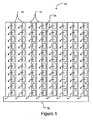
図1は、多くの電子カメラで使用されているタイプのCCD(インターライントランスファ電荷結合素子)10のためのセンサ配置図を示す。CCD10は、受光要素を有する複数の撮像領域12と、垂直レジスタ14を有する記憶領域を含む。図示された実施例では、撮像領域12は、水平方向で垂直レジスタ14と交互する。撮像領域12は、それぞれ複数の画素16を含む。各々の画素16は、電荷を蓄えるセンサを含む。蓄えられる電荷の量は、センサによって検出される光子の数に依存する。図1に矢印で示すように、画像が露出(exposed)された後、画素16内に蓄えられた電荷を特徴付ける画素データは、垂直レジスタ14に移される。
FIG. 1 shows a sensor layout for a CCD (interline transfer charge coupled device) 10 of the type used in many electronic cameras. The
垂直レジスタ14(「コラムレジスタ」と呼ばれることもある)を不透明なマスク層(例:アルミニウム条片)で覆うことによって、出射する垂直レジスタ14から光が入射するのを防ぐことができる。垂直レジスタ14は、画素データが垂直レジスタ14の下方の水平レジスタ18に移されるときに電荷の特性を保存する。(この記述で用いられる「垂直」、「水平」、「下方」という言葉は、特定の物理的方向というよりも、図1に示す要素の方向を基準にする。)画素データは、一般に水平レジスタ18から、1個以上の増幅器および/または信号処理回路(図示略)を通って、アナログ/デジタル変換器に読出される。
By covering the vertical register 14 (sometimes referred to as a “column register”) with an opaque mask layer (eg, aluminum strip), light can be prevented from entering the outgoing
図2は、第1CCD10Aと第2CCD10Bを装備した電子カメラ20を示す。第1CCD10Aと第2CCD10Bは、それぞれ図1のCCD10と構造が類似してよいが、異なる特性を有してよい。たとえば第1CCD10Aは、標準ダイナミックレンジを有する高解像度センサを含んでよい。第2CCD10Bは、高ダイナミックレンジを有する低解像度センサを含んでよい。ある実施例において第1CCD10Aの解像度は、たとえば1920×1080以上であってよい。第2CCD10Bの解像度は、たとえば各方向で第1CCD10Aの解像度の4分の1と低くてよい。また、ある実施例において第1CCD10Aはカラーセンサを含み、第2CCD10Bはモノクロセンサを含んでよい。
FIG. 2 shows an electronic camera 20 equipped with a
電子カメラ20は、画像から光が選択的に第1CCD10Aと第2CCD10Bに到達することを可能にする機械的シャッタ22を含む。機械的シャッタ22が開いているとき、入射光は、光学システム(図示略)によって第1CCD10Aと第2CCD10Bに焦点を合わされる。コントローラ24は、シャッタ制御線26を用いて、機械的シャッタ22の開閉を制御する。コントローラ24は、第1CCD制御線28Aと第2CCD制御線28Bを用いて、第1CCD10Aと第2CCD10Bの垂直レジスタ14と水平レジスタ18のクロック動作も制御する。コントローラ24は、たとえばマイクロプロセッサ実行ソフトウェア(例:ファームウェア25)を含んでよい。コントローラ24は、第1データ線30Aと第2データ線30Bを用いて、第1CCD10Aと第2CCD10Bから画素データを受取る。
The electronic camera 20 includes a
コントローラ24は、画素データをメモリ32に記憶できる。つまりコントローラ24は、画素データをメモリ32、たとえば高ダイナミックレンジ情報を含む第1データ部分と、トーンマップデータを含む第2データ部分とを有する高ダイナミックレンジデータ構造に記憶できる。これは、2004年12月24日に提出された特許文献1に記載され、参照によって本願に編入される。
The
コントローラ24は、また画素データに基づく画像を画面34に表示できる。画面34は、たとえば観察者が画像を見るのを困難にしかねない周囲照明を克服するために高輝度ディスプレイを含んでよい。代替として画面34は、たとえば2002年2月27日に提出された特許文献2、または2003年3月13日に提出された特許文献3に開示された高ダイナミックレンジディスプレイ装置を含んでよい。いずれの出願も参照によって本願に編入される。このような実施例において、電子カメラ20は、高ダイナミックレンジディスプレイ装置を周囲照明から遮蔽するためのフード(hood)を含むことができる。
The
電子カメラ20は、ユーザがコントローラ24と相互作用することを可能にするインタフェース35も含む。インタフェース35は、シャッタリリース36を含む。シャッタリリース36は、タイマ、シャッタリリースボタン、または類似のものによってトリガされ得る。
The electronic camera 20 also includes an interface 35 that allows a user to interact with the
図3は、複数のCCDを有するカメラ、たとえば図2の電子カメラ20を使用して高ダイナミックレンジ(HDR)画像を生成するための方法100を示す。方法100は、CCDを有するカメラとの関連で記述されているが、方法100は、3個以上のCCDを有するカメラを使用しても実施し得ると理解されるべきである。
FIG. 3 illustrates a
方法100は、ブロックS102で、電子カメラ20のレンズを適切な絞りに調整する。絞りは、電子カメラ20の露出制御回路によって調整できる。デジタルカメラで機械的シャッタ22の絞りを調整するための適切なシステムは、当業界において多種多様なものが知られている。そのようなシステムは、絞りを、ユーザが設定した値に調整するか、または絞りを、検出された光のレベルに基づくアルゴリズムに従って調整してよい。
The
ブロックS104で、第1CCD10Aと第2CCD10Bの画素に蓄えられた電荷が消去されて、画像把捉期間(image capture period)が開始する。ブロックS106で、電子カメラ20のタイマは、画像把捉のために設定された時間をカウントダウンする。第1CCD10Aと第2CCD10Bは、それぞれ同じ時間露出されてよいが、しかしこのことは、すべての実施例において必要とは限らない。追加または代替として、第1CCD10Aと第2CCD10Bのいずれか一方または両方は、画像把捉期間中に多重露出を把捉するために、たとえば2005年9月26日に提出された特許文献4と、2006年7月24日に提出された特許文献5に記載されている技術を用いて操作され得る。いずれの出願も参照によって本願に編入される。
In block S104, the charges stored in the pixels of the
第1CCD10Aと第2CCD10Bが互いに等しい時間露出されない実施例では、第1CCD10Aと第2CCD10Bからのデータを組合わせるときに、時間領域補間が使用されてよい。第1CCD10Aと第2CCD10Bを露出後、ブロックS108で、第1CCD10Aと第2CCD10Bの画素に蓄えられた電荷を表すデータが読出される。第1CCD10Aと第2CCD10Bがそれぞれ1回だけ露出される実施例では、データは、画像把捉期間の後で読出されてよい。第1CCD10Aと第2CCD10Bのいずれか一方または両方が多重露出を把捉する実施例では、データの幾つかが画像把捉期間中に読出され、データの幾つかが画像把捉期間中の後で読出されてよい。
In embodiments where the
ブロックS110で、第1CCD10Aと第2CCD10Bからのデータが組合わされて、高ダイナミックレンジ画像を生成する。第1CCD10Aと第2CCD10Bからのデータを組合わせることは、たとえば特許文献1に記載されている技術を使用することを含んでよい。第1CCD10Aと第2CCD10Bからのデータの組合わせは、メモリに記憶され得る。組合わされたデータは、たとえば特許文献1に記載されているように、高ダイナミックレンジ情報を含む第1データ部分と、トーンマップデータを含む第2データ部分とを有するデータ構造に記憶されてよく、それによって組合わされたデータから、標
準画像とダイナミックレンジ画像が生成され得る。
In block S110, the data from the
発明者は、高ダイナミックレンジ画像を生成するために2個のCCDで一般に十分であることを究明したが、本発明の特定の実施例に従うカメラは、3個以上のCCDを含んでよい。たとえば3個以上のCCDを使用することによって、結果として生じる画像に追加的なダイナミックレンジおよび/または色が与えられる。また、幾つかの実施例において、2個以上のCCDのうちの少なくとも1個が、特に高ダイナミックレンジ画素を把捉するために適合されてよい。 Although the inventor has determined that two CCDs are generally sufficient to produce a high dynamic range image, a camera according to certain embodiments of the invention may include more than two CCDs. For example, using more than two CCDs provides additional dynamic range and / or color to the resulting image. Also, in some embodiments, at least one of the two or more CCDs may be particularly adapted to capture high dynamic range pixels.
カメラ内のコントローラは、2個以上のCCDからのデータを組合わせて高ダイナミックレンジ画像を生成して、高ダイナミックレンジ画像を、何らかの適切な高ダイナミックレンジフォーマットに保存するようにプログラムされてよい。これが行われる所では、高ダイナミックレンジ画像が、実質的にユーザに見える方法で得られることが理解できる。 A controller in the camera may be programmed to combine data from two or more CCDs to generate a high dynamic range image and save the high dynamic range image in any suitable high dynamic range format. It can be seen that where this is done, the high dynamic range image is obtained in a manner that is substantially visible to the user.
本発明の特定の実施形態は、プロセッサに、本発明の方法を実施させるソフトウェア命令を実行するコンピュータプロセッサを含む。たとえば電子カメラ用のコントローラ内の1個以上のプロセッサは、プロセッサにアクセス可能なプログラムメモリ内のソフトウェアの命令を実行することによって、図3の方法を実施できる。本発明は、プログラム製品の形でも提供され得る。このプログラム製品は、データプロセッサによって実行されると、本発明の方法を実行させる命令を含んだ1組のコンピュータ可読信号を伝達する何らかの媒体を含んでよい。本発明に従うプログラム製品は、非常に多様な形態のいずれであってもよい。たとえばプログラム製品は、フロッピー(登録商標)ディスク、ハードディスクドライブなどの磁気データ記憶媒体、CD−ROM、DVDなどの光学データ記憶媒体、ROM、フラッシュRAMなどの電子データ記憶媒体を含む物理的媒体か、あるいはデジタル通信回線やアナログ通信回線などの通信型媒体を含んでよい。プログラム製品上のコンピュータ可読信号は、光学的に圧縮または暗号化されてよい。 Particular embodiments of the present invention include computer processors that execute software instructions that cause a processor to perform the methods of the present invention. For example, one or more processors in a controller for an electronic camera can implement the method of FIG. 3 by executing software instructions in a program memory accessible to the processor. The present invention may also be provided in the form of a program product. The program product may include any medium that, when executed by a data processor, conveys a set of computer readable signals that include instructions that cause the method of the present invention to be performed. The program product according to the present invention may be in any of a wide variety of forms. For example, the program product may be a physical medium including a floppy data disk, a magnetic data storage medium such as a hard disk drive, an optical data storage medium such as a CD-ROM or DVD, an electronic data storage medium such as a ROM or flash RAM, Alternatively, a communication type medium such as a digital communication line or an analog communication line may be included. The computer readable signal on the program product may be optically compressed or encrypted.
上記において構成要素(例:ソフトウェアモジュール、プロセッサ、組立品、装置、回路など)が言及される場合、別途指示がない限り、構成要素の言及(「手段」に対する言及を含む)は、構造的には開示された構造と同等ではないが、本発明の図示された実施例における機能を実行する構成要素を含め、記載された構成要素の機能を実行する何らかの構成要素(即ち機能的同等物)を、構成要素と同等物として含むものと解釈されなければならない。 Where components (eg, software modules, processors, assemblies, devices, circuits, etc.) are referred to above, references to the components (including references to “means”) are structurally unless otherwise indicated. Is not equivalent to the disclosed structure, but includes any component (ie, functional equivalent) that performs the function of the described component, including the component that performs the function of the illustrated embodiment of the invention. Should be construed as including as component equivalents.
上記の開示を踏まえて当業者に明らかなように、本発明の実施においては本発明の趣旨と範囲から逸脱することなく、様々な変更および変容が可能である。従って、本発明の範囲は以下の請求項によって定義される実質に従って理解されるべきである。 As will be apparent to those skilled in the art in light of the above disclosure, various changes and modifications can be made in the practice of the invention without departing from the spirit and scope of the invention. Accordingly, the scope of the invention should be understood according to the substance defined by the following claims.
Claims (19)
光を選択的に2個以上の前記画像センサアレイ(10A,10B)に到達できるようにするシャッタ(22)と;
前記画像センサアレイ(10A,10B)から選択的に画素データを読出す読出回路と;
前記シャッタ(22)と読出回路を制御するように構成されたコントローラ(24)とを含む電子カメラ(20)であって、
前記コントローラはプロセッサとメモリとを有し、前記メモリはコンピュータ読取可能に埋込まれたコードを有し、前記コードが前記プロセッサによって実行されることで前記コントローラ(24)は、2個以上の前記画像センサアレイ(10A,10B)が前記画素データを把捉するために、画像把捉期間中に前記シャッタ(22)を開かせ、かつ2個以上の前記画像センサアレイ(10A,10B)から前記画素データを読出す
ことを特徴とする、電子カメラ(20)。 Two or more having at least one low resolution image sensor array (10B) having a high dynamic range and at least one high resolution image sensor array (10A) having a standard dynamic range lower than the high dynamic range. An image sensor array (10A, 10B), wherein the low resolution image sensor array having the high dynamic range captures a wider range of light intensity than the high resolution image sensor array having the standard dynamic range. Being configured to do;
A shutter (22) that allows light to selectively reach two or more of the image sensor arrays (10A, 10B);
A readout circuit for selectively reading out pixel data from the image sensor array (10A, 10B);
An electronic camera (20) comprising the shutter (22) and a controller (24) configured to control a readout circuit,
The controller includes a processor and a memory, and the memory includes code embedded in a computer readable manner, and the controller (24) is executed by the processor so that the controller (24) includes two or more of the codes. In order for the image sensor array (10A, 10B) to capture the pixel data, the shutter (22) is opened during the image capturing period, and the pixel data from two or more image sensor arrays (10A, 10B). An electronic camera (20), characterized in that
請求項1記載の電子カメラ(20)。 The code is executed by the processor so that the controller (24) stores the pixel data from two or more of the image sensor arrays (10A, 10B) in a high dynamic range image data structure.
The electronic camera (20) according to claim 1.
高ダイナミックレンジ情報を含む第1データ部分と;
トーンマップデータを含む第2データ部分と
を有する、
請求項2記載の電子カメラ(20)。 The high dynamic range image data structure is:
A first data portion containing high dynamic range information;
A second data portion including tone map data;
The electronic camera (20) according to claim 2.
請求項1記載の電子カメラ(20)。 As the code is executed by the processor, the controller (24) combines the pixel data read from two or more image sensor arrays (10A, 10B) to generate high dynamic range image data. Generate,
The electronic camera (20) according to claim 1.
請求項4記載の電子カメラ(20)。 The electronic camera (20) further includes a screen (34) for displaying an image based on the high dynamic range image data.
The electronic camera (20) according to claim 4.
請求項5記載の電子カメラ(20)。 The screen includes a high dynamic range display device (34) configured to display a high dynamic range image;
The electronic camera (20) according to claim 5.
請求項6記載の電子カメラ(20)。 The electronic camera (20) further includes a hood that shields the high dynamic range display device (34).
The electronic camera (20) according to claim 6.
請求項1記載の電子カメラ(20)。 The low resolution image sensor array (10B) includes a charge coupled device adapted to capture high dynamic range pixels.
The electronic camera (20) according to claim 1.
請求項1記載の電子カメラ(20)。 The low resolution image sensor array (10B) uses 16 bits or 32 bits of each color to represent the level of brightness.
The electronic camera (20) according to claim 1.
請求項1記載の電子カメラ(20)。 The low resolution image sensor array (10B) and the high resolution image sensor array (10A) are different types of image sensor arrays.
The electronic camera (20) according to claim 1.
前記高解像度画像センサアレイ(10A)は、カラー画像センサアレイを含む、
請求項1記載の電子カメラ(20)。 The low resolution image sensor array (10B) includes a monochrome image sensor array;
The high resolution image sensor array (10A) includes a color image sensor array,
The electronic camera (20) according to claim 1.
請求項1記載の電子カメラ(20)。 The resolution of the high resolution image sensor array (10A) is at least 1920 × 1080,
The electronic camera (20) according to claim 1.
前記低解像度画像センサアレイ(10B)の解像度は、1920×1080×1/4である、
請求項1記載の電子カメラ(20)。 The resolution of the high resolution image sensor array (10A) is at least 1920 × 1080,
The resolution of the low-resolution image sensor array (10B) is 1920 × 1080 × 1/4.
The electronic camera (20) according to claim 1.
有する前記低解像度画像センサアレイは、前記標準ダイナミックレンジを有する前記高解像度画像センサアレイよりも、光の輝度のより広いレンジを把捉するように構成され、
前記画像生成方法は、
画像把捉期間中に光が、選択的に2個以上の前記画像センサアレイ(10A,10B)に到達させる光選択到達ステップと;
前記画像把捉期間中に2個以上の前記画像センサアレイ(10A,10B)によって把捉された画素データを、読出す画素データ読出ステップと;
2個以上の前記画像センサアレイ(10A,10B)から読出した前記画素データを組合わせることによって、高ダイナミックレンジ画像データを生成する画像データ生成ステップと
を有することを特徴とする、画像生成方法。 An image generation method for generating a high dynamic range image by an electronic camera (20), wherein the electronic camera (20) includes at least one low resolution image sensor array (10B) having a high dynamic range; The low resolution having two or more image sensor arrays (10A, 10B) having at least one high resolution image sensor array (10A) having a standard dynamic range lower than the high dynamic range and having the high dynamic range The image sensor array is configured to capture a wider range of light brightness than the high resolution image sensor array having the standard dynamic range;
The image generation method includes:
A light selective reaching step in which light selectively reaches two or more of the image sensor arrays (10A, 10B) during an image capture period;
A pixel data reading step of reading out pixel data captured by the two or more image sensor arrays (10A, 10B) during the image capturing period;
An image data generation method comprising: an image data generation step of generating high dynamic range image data by combining the pixel data read from two or more image sensor arrays (10A, 10B).
請求項14記載の画像生成方法。 The light selective reaching step includes capturing multiple exposures by one of the image sensor arrays (10A, 10B);
The image generation method according to claim 14.
請求項15記載の画像生成方法。 The pixel data reading step includes reading an initial exposure of the image sensor array (10A, 10B) during the image capture period.
The image generation method according to claim 15.
請求項14記載の画像生成方法。 The image generation method further includes an image data storage step of storing high dynamic range image data in a memory (32) accessible by the electronic camera (20).
The image generation method according to claim 14.
請求項17記載の画像生成方法。 The image data storing step includes storing the high dynamic range image data in a data structure having a first data portion including high dynamic range information and a second data portion including tone map data.
The image generation method according to claim 17.
請求項14記載の画像生成方法。 The low resolution image sensor array (10B) uses 16 bits or 32 bits of each color to represent the level of brightness.
The image generation method according to claim 14.
Applications Claiming Priority (3)
| Application Number | Priority Date | Filing Date | Title |
|---|---|---|---|
| US11/609,837 US8242426B2 (en) | 2006-12-12 | 2006-12-12 | Electronic camera having multiple sensors for capturing high dynamic range images and related methods |
| US11/609,837 | 2006-12-12 | ||
| PCT/US2007/087301 WO2008073991A2 (en) | 2006-12-12 | 2007-12-12 | Hdr camera with multiple sensors |
Related Child Applications (1)
| Application Number | Title | Priority Date | Filing Date |
|---|---|---|---|
| JP2014077656A Division JP2014161055A (en) | 2006-12-12 | 2014-04-04 | High dynamic range camera having multiple sensors |
Publications (3)
| Publication Number | Publication Date |
|---|---|
| JP2010512719A JP2010512719A (en) | 2010-04-22 |
| JP2010512719A5 JP2010512719A5 (en) | 2011-04-14 |
| JP5551937B2 true JP5551937B2 (en) | 2014-07-16 |
Family
ID=39512472
Family Applications (3)
| Application Number | Title | Priority Date | Filing Date |
|---|---|---|---|
| JP2009541566A Active JP5551937B2 (en) | 2006-12-12 | 2007-12-12 | High dynamic range camera with multiple sensors and image generation method |
| JP2014077656A Pending JP2014161055A (en) | 2006-12-12 | 2014-04-04 | High dynamic range camera having multiple sensors |
| JP2017008539A Active JP6360211B2 (en) | 2006-12-12 | 2017-01-20 | High dynamic range camera with multiple sensors |
Family Applications After (2)
| Application Number | Title | Priority Date | Filing Date |
|---|---|---|---|
| JP2014077656A Pending JP2014161055A (en) | 2006-12-12 | 2014-04-04 | High dynamic range camera having multiple sensors |
| JP2017008539A Active JP6360211B2 (en) | 2006-12-12 | 2017-01-20 | High dynamic range camera with multiple sensors |
Country Status (9)
| Country | Link |
|---|---|
| US (3) | US8242426B2 (en) |
| EP (1) | EP2123026A4 (en) |
| JP (3) | JP5551937B2 (en) |
| KR (1) | KR101449973B1 (en) |
| CN (1) | CN101622862B (en) |
| CA (1) | CA2672143C (en) |
| HK (1) | HK1139263A1 (en) |
| MX (1) | MX2009006185A (en) |
| WO (1) | WO2008073991A2 (en) |
Families Citing this family (92)
| Publication number | Priority date | Publication date | Assignee | Title |
|---|---|---|---|---|
| US8242426B2 (en) * | 2006-12-12 | 2012-08-14 | Dolby Laboratories Licensing Corporation | Electronic camera having multiple sensors for capturing high dynamic range images and related methods |
| US8866920B2 (en) | 2008-05-20 | 2014-10-21 | Pelican Imaging Corporation | Capturing and processing of images using monolithic camera array with heterogeneous imagers |
| US8902321B2 (en) | 2008-05-20 | 2014-12-02 | Pelican Imaging Corporation | Capturing and processing of images using monolithic camera array with heterogeneous imagers |
| US11792538B2 (en) | 2008-05-20 | 2023-10-17 | Adeia Imaging Llc | Capturing and processing of images including occlusions focused on an image sensor by a lens stack array |
| CN102292187B (en) * | 2008-11-21 | 2015-12-09 | 普雷茨特两合公司 | For monitoring the method and apparatus of the laser processing procedure will implemented on workpiece and there is the laser Machining head of this device |
| US20100225783A1 (en) * | 2009-03-04 | 2010-09-09 | Wagner Paul A | Temporally Aligned Exposure Bracketing for High Dynamic Range Imaging |
| JP5282689B2 (en) * | 2009-07-23 | 2013-09-04 | ソニー株式会社 | Imaging apparatus and imaging method |
| US8514491B2 (en) | 2009-11-20 | 2013-08-20 | Pelican Imaging Corporation | Capturing and processing of images using monolithic camera array with heterogeneous imagers |
| SG10201503516VA (en) | 2010-05-12 | 2015-06-29 | Pelican Imaging Corp | Architectures for imager arrays and array cameras |
| JP5545016B2 (en) * | 2010-05-12 | 2014-07-09 | ソニー株式会社 | Imaging device |
| US8462221B2 (en) * | 2010-11-03 | 2013-06-11 | Eastman Kodak Company | Method for producing high dynamic range images |
| US8878950B2 (en) | 2010-12-14 | 2014-11-04 | Pelican Imaging Corporation | Systems and methods for synthesizing high resolution images using super-resolution processes |
| US9077910B2 (en) | 2011-04-06 | 2015-07-07 | Dolby Laboratories Licensing Corporation | Multi-field CCD capture for HDR imaging |
| WO2012155119A1 (en) | 2011-05-11 | 2012-11-15 | Pelican Imaging Corporation | Systems and methods for transmitting and receiving array camera image data |
| US20130265459A1 (en) | 2011-06-28 | 2013-10-10 | Pelican Imaging Corporation | Optical arrangements for use with an array camera |
| US9270875B2 (en) * | 2011-07-20 | 2016-02-23 | Broadcom Corporation | Dual image capture processing |
| RU2472299C1 (en) * | 2011-08-24 | 2013-01-10 | Вячеслав Михайлович Смелков | Television camera for viewing in conditions of low illumination and/or low brightness of objects |
| RU2472300C1 (en) * | 2011-09-13 | 2013-01-10 | Вячеслав Михайлович Смелков | Television camera for viewing in conditions of illumination and/or brightness of objects varying in entire field of view |
| WO2013043761A1 (en) | 2011-09-19 | 2013-03-28 | Pelican Imaging Corporation | Determining depth from multiple views of a scene that include aliasing using hypothesized fusion |
| WO2013049699A1 (en) | 2011-09-28 | 2013-04-04 | Pelican Imaging Corporation | Systems and methods for encoding and decoding light field image files |
| RU2472301C1 (en) * | 2011-09-29 | 2013-01-10 | Вячеслав Михайлович Смелков | Television camera for viewing in conditions of low illumination and/or low brightness of objects |
| RU2484597C1 (en) * | 2011-12-21 | 2013-06-10 | Вячеслав Михайлович Смелков | Television camera for viewing in conditions of low illumination and/or low brightness of objects |
| RU2481724C1 (en) * | 2011-12-21 | 2013-05-10 | Вячеслав Михайлович Смелков | Television camera for viewing in conditions of low illumination and/or low brightness of objects |
| EP2817955B1 (en) | 2012-02-21 | 2018-04-11 | FotoNation Cayman Limited | Systems and methods for the manipulation of captured light field image data |
| US9210392B2 (en) | 2012-05-01 | 2015-12-08 | Pelican Imaging Coporation | Camera modules patterned with pi filter groups |
| US8993974B2 (en) * | 2012-06-12 | 2015-03-31 | Nikon Corporation | Color time domain integration camera having a single charge coupled device and fringe projection auto-focus system |
| US9100635B2 (en) | 2012-06-28 | 2015-08-04 | Pelican Imaging Corporation | Systems and methods for detecting defective camera arrays and optic arrays |
| US20140002674A1 (en) | 2012-06-30 | 2014-01-02 | Pelican Imaging Corporation | Systems and Methods for Manufacturing Camera Modules Using Active Alignment of Lens Stack Arrays and Sensors |
| CN107346061B (en) | 2012-08-21 | 2020-04-24 | 快图有限公司 | System and method for parallax detection and correction in images captured using an array camera |
| EP2888698A4 (en) | 2012-08-23 | 2016-06-29 | Pelican Imaging Corp | Feature based high resolution motion estimation from low resolution images captured using an array source |
| WO2014043641A1 (en) | 2012-09-14 | 2014-03-20 | Pelican Imaging Corporation | Systems and methods for correcting user identified artifacts in light field images |
| US9143673B2 (en) | 2012-09-19 | 2015-09-22 | Google Inc. | Imaging device with a plurality of pixel arrays |
| CN104685860A (en) | 2012-09-28 | 2015-06-03 | 派力肯影像公司 | Generating images from light fields utilizing virtual viewpoints |
| US9143711B2 (en) | 2012-11-13 | 2015-09-22 | Pelican Imaging Corporation | Systems and methods for array camera focal plane control |
| US9462164B2 (en) | 2013-02-21 | 2016-10-04 | Pelican Imaging Corporation | Systems and methods for generating compressed light field representation data using captured light fields, array geometry, and parallax information |
| US9374512B2 (en) | 2013-02-24 | 2016-06-21 | Pelican Imaging Corporation | Thin form factor computational array cameras and modular array cameras |
| US9774789B2 (en) | 2013-03-08 | 2017-09-26 | Fotonation Cayman Limited | Systems and methods for high dynamic range imaging using array cameras |
| US8866912B2 (en) | 2013-03-10 | 2014-10-21 | Pelican Imaging Corporation | System and methods for calibration of an array camera using a single captured image |
| US9521416B1 (en) | 2013-03-11 | 2016-12-13 | Kip Peli P1 Lp | Systems and methods for image data compression |
| US9888194B2 (en) | 2013-03-13 | 2018-02-06 | Fotonation Cayman Limited | Array camera architecture implementing quantum film image sensors |
| US9124831B2 (en) | 2013-03-13 | 2015-09-01 | Pelican Imaging Corporation | System and methods for calibration of an array camera |
| US9519972B2 (en) | 2013-03-13 | 2016-12-13 | Kip Peli P1 Lp | Systems and methods for synthesizing images from image data captured by an array camera using restricted depth of field depth maps in which depth estimation precision varies |
| US9106784B2 (en) | 2013-03-13 | 2015-08-11 | Pelican Imaging Corporation | Systems and methods for controlling aliasing in images captured by an array camera for use in super-resolution processing |
| US9100586B2 (en) | 2013-03-14 | 2015-08-04 | Pelican Imaging Corporation | Systems and methods for photometric normalization in array cameras |
| WO2014159779A1 (en) | 2013-03-14 | 2014-10-02 | Pelican Imaging Corporation | Systems and methods for reducing motion blur in images or video in ultra low light with array cameras |
| US10122993B2 (en) | 2013-03-15 | 2018-11-06 | Fotonation Limited | Autofocus system for a conventional camera that uses depth information from an array camera |
| US9497429B2 (en) | 2013-03-15 | 2016-11-15 | Pelican Imaging Corporation | Extended color processing on pelican array cameras |
| US9445003B1 (en) | 2013-03-15 | 2016-09-13 | Pelican Imaging Corporation | Systems and methods for synthesizing high resolution images using image deconvolution based on motion and depth information |
| WO2014150856A1 (en) | 2013-03-15 | 2014-09-25 | Pelican Imaging Corporation | Array camera implementing quantum dot color filters |
| JP2016524125A (en) | 2013-03-15 | 2016-08-12 | ペリカン イメージング コーポレイション | System and method for stereoscopic imaging using a camera array |
| US9633442B2 (en) | 2013-03-15 | 2017-04-25 | Fotonation Cayman Limited | Array cameras including an array camera module augmented with a separate camera |
| US9955084B1 (en) | 2013-05-23 | 2018-04-24 | Oliver Markus Haynold | HDR video camera |
| KR102106537B1 (en) | 2013-09-27 | 2020-05-04 | 삼성전자주식회사 | Method for generating a High Dynamic Range image, device thereof, and system thereof |
| US9898856B2 (en) | 2013-09-27 | 2018-02-20 | Fotonation Cayman Limited | Systems and methods for depth-assisted perspective distortion correction |
| US9185276B2 (en) | 2013-11-07 | 2015-11-10 | Pelican Imaging Corporation | Methods of manufacturing array camera modules incorporating independently aligned lens stacks |
| US10119808B2 (en) | 2013-11-18 | 2018-11-06 | Fotonation Limited | Systems and methods for estimating depth from projected texture using camera arrays |
| EP3075140B1 (en) | 2013-11-26 | 2018-06-13 | FotoNation Cayman Limited | Array camera configurations incorporating multiple constituent array cameras |
| US10089740B2 (en) | 2014-03-07 | 2018-10-02 | Fotonation Limited | System and methods for depth regularization and semiautomatic interactive matting using RGB-D images |
| CN104954627B (en) * | 2014-03-24 | 2019-03-08 | 联想(北京)有限公司 | A kind of information processing method and electronic equipment |
| US9247117B2 (en) | 2014-04-07 | 2016-01-26 | Pelican Imaging Corporation | Systems and methods for correcting for warpage of a sensor array in an array camera module by introducing warpage into a focal plane of a lens stack array |
| CN103986875A (en) * | 2014-05-29 | 2014-08-13 | 宇龙计算机通信科技(深圳)有限公司 | Image acquiring device, method and terminal and video acquiring method |
| US9521319B2 (en) | 2014-06-18 | 2016-12-13 | Pelican Imaging Corporation | Array cameras and array camera modules including spectral filters disposed outside of a constituent image sensor |
| US10277771B1 (en) | 2014-08-21 | 2019-04-30 | Oliver Markus Haynold | Floating-point camera |
| US10250871B2 (en) | 2014-09-29 | 2019-04-02 | Fotonation Limited | Systems and methods for dynamic calibration of array cameras |
| US10225485B1 (en) | 2014-10-12 | 2019-03-05 | Oliver Markus Haynold | Method and apparatus for accelerated tonemapping |
| US9942474B2 (en) | 2015-04-17 | 2018-04-10 | Fotonation Cayman Limited | Systems and methods for performing high speed video capture and depth estimation using array cameras |
| US9819889B2 (en) | 2015-08-07 | 2017-11-14 | Omnivision Technologies, Inc. | Method and system to implement a stacked chip high dynamic range image sensor |
| CN105578005B (en) * | 2015-12-18 | 2018-01-19 | 广东欧珀移动通信有限公司 | Imaging method, imaging device and the electronic installation of imaging sensor |
| KR102603426B1 (en) | 2016-06-27 | 2023-11-20 | 삼성전자주식회사 | Apparatus and method for processing an image |
| CN112565622B (en) | 2016-07-01 | 2022-10-28 | 麦克赛尔株式会社 | Image capturing apparatus |
| CN106161979B (en) * | 2016-07-29 | 2017-08-25 | 广东欧珀移动通信有限公司 | High dynamic range images image pickup method, device and terminal device |
| RU2631828C1 (en) * | 2016-09-21 | 2017-09-27 | Вячеслав Михайлович Смелков | Computer system of panoramic television observation |
| RU2631830C1 (en) * | 2016-10-31 | 2017-09-27 | Вячеслав Михайлович Смелков | Computer system of panoramic television observation |
| US10482618B2 (en) | 2017-08-21 | 2019-11-19 | Fotonation Limited | Systems and methods for hybrid depth regularization |
| RU2670419C1 (en) * | 2017-12-01 | 2018-10-23 | Вячеслав Михайлович Смелков | Method of controlling the sensitivity of a television camera on a ccd matrix under conditions of complex illumination and / or complex brightness of objects |
| US10757320B2 (en) | 2017-12-28 | 2020-08-25 | Waymo Llc | Multiple operating modes to expand dynamic range |
| RU2691942C1 (en) * | 2018-09-13 | 2019-06-19 | Вячеслав Михайлович Смелков | Method of controlling sensitivity of a television camera on a ccd matrix in conditions of high illumination and/or complex brightness of objects |
| CN110278375B (en) * | 2019-06-28 | 2021-06-15 | Oppo广东移动通信有限公司 | Image processing method, image processing device, storage medium and electronic equipment |
| KR102646521B1 (en) | 2019-09-17 | 2024-03-21 | 인트린식 이노베이션 엘엘씨 | Surface modeling system and method using polarization cue |
| CA3157194C (en) | 2019-10-07 | 2023-08-29 | Boston Polarimetrics, Inc. | Systems and methods for augmentation of sensor systems and imaging systems with polarization |
| WO2021108002A1 (en) | 2019-11-30 | 2021-06-03 | Boston Polarimetrics, Inc. | Systems and methods for transparent object segmentation using polarization cues |
| KR20220132620A (en) | 2020-01-29 | 2022-09-30 | 인트린식 이노베이션 엘엘씨 | Systems and methods for characterizing object pose detection and measurement systems |
| KR20220133973A (en) | 2020-01-30 | 2022-10-05 | 인트린식 이노베이션 엘엘씨 | Systems and methods for synthesizing data to train statistical models for different imaging modalities, including polarized images |
| EP3902240B1 (en) * | 2020-04-22 | 2022-03-30 | Axis AB | Method, device, camera and software for performing electronic image stabilization of a high dynamic range image |
| CN111526299B (en) * | 2020-04-28 | 2022-05-17 | 荣耀终端有限公司 | High dynamic range image synthesis method and electronic equipment |
| US11953700B2 (en) | 2020-05-27 | 2024-04-09 | Intrinsic Innovation Llc | Multi-aperture polarization optical systems using beam splitters |
| US11474743B2 (en) * | 2020-08-13 | 2022-10-18 | Micron Technology, Inc. | Data modification |
| JP7231598B2 (en) * | 2020-11-05 | 2023-03-01 | マクセル株式会社 | Imaging device |
| US11954886B2 (en) | 2021-04-15 | 2024-04-09 | Intrinsic Innovation Llc | Systems and methods for six-degree of freedom pose estimation of deformable objects |
| US11290658B1 (en) | 2021-04-15 | 2022-03-29 | Boston Polarimetrics, Inc. | Systems and methods for camera exposure control |
| US11689813B2 (en) | 2021-07-01 | 2023-06-27 | Intrinsic Innovation Llc | Systems and methods for high dynamic range imaging using crossed polarizers |
| WO2023069451A1 (en) * | 2021-10-18 | 2023-04-27 | Arthrex, Inc. | Surgical camera system with high dynamic range and fluorescent imaging |
Family Cites Families (39)
| Publication number | Priority date | Publication date | Assignee | Title |
|---|---|---|---|---|
| US4652909A (en) * | 1982-09-14 | 1987-03-24 | New York Institute Of Technology | Television camera and recording system for high definition television having imagers of different frame rate |
| CA2074488A1 (en) * | 1990-02-16 | 1991-08-17 | Georges Cornuejols | Device for increasing the dynamic range of a camera |
| US5420635A (en) | 1991-08-30 | 1995-05-30 | Fuji Photo Film Co., Ltd. | Video camera, imaging method using video camera, method of operating video camera, image processing apparatus and method, and solid-state electronic imaging device |
| JP3517430B2 (en) * | 1993-03-31 | 2004-04-12 | キヤノン株式会社 | Image processing system |
| US6204881B1 (en) * | 1993-10-10 | 2001-03-20 | Canon Kabushiki Kaisha | Image data processing apparatus which can combine a plurality of images at different exposures into an image with a wider dynamic range |
| US5801773A (en) * | 1993-10-29 | 1998-09-01 | Canon Kabushiki Kaisha | Image data processing apparatus for processing combined image signals in order to extend dynamic range |
| NZ332626A (en) * | 1997-11-21 | 2000-04-28 | Matsushita Electric Ind Co Ltd | Expansion of dynamic range for video camera |
| US6864916B1 (en) | 1999-06-04 | 2005-03-08 | The Trustees Of Columbia University In The City Of New York | Apparatus and method for high dynamic range imaging using spatially varying exposures |
| US6198505B1 (en) * | 1999-07-19 | 2001-03-06 | Lockheed Martin Corp. | High resolution, high speed digital camera |
| JP2001136434A (en) * | 1999-11-09 | 2001-05-18 | Ricoh Co Ltd | Image pickup device |
| TW469733B (en) * | 2000-01-07 | 2001-12-21 | Dynacolor Inc | Method of dynamically modulating image brightness and image catching device using the method |
| US7084905B1 (en) | 2000-02-23 | 2006-08-01 | The Trustees Of Columbia University In The City Of New York | Method and apparatus for obtaining high dynamic range images |
| US7623168B2 (en) | 2000-07-13 | 2009-11-24 | Eastman Kodak Company | Method and apparatus to extend the effective dynamic range of an image sensing device |
| US6788338B1 (en) * | 2000-11-20 | 2004-09-07 | Petko Dimitrov Dinev | High resolution video camera apparatus having two image sensors and signal processing |
| US6542698B2 (en) | 2001-01-19 | 2003-04-01 | Kakuyo Co., Ltd. | Shading hood for digital camera having liquid crystal screen |
| ES2844273T3 (en) | 2001-02-27 | 2021-07-21 | Dolby Laboratories Licensing Corp | Method and device for exposing an image |
| JP3546853B2 (en) * | 2001-03-23 | 2004-07-28 | ミノルタ株式会社 | Imaging device and image reproduction system |
| JP2003037757A (en) * | 2001-07-25 | 2003-02-07 | Fuji Photo Film Co Ltd | Imaging unit |
| JP2003101886A (en) * | 2001-09-25 | 2003-04-04 | Olympus Optical Co Ltd | Image pickup device |
| JP4154157B2 (en) | 2002-02-25 | 2008-09-24 | 株式会社東芝 | Imaging device |
| AU2003220595A1 (en) | 2002-03-27 | 2003-10-13 | The Trustees Of Columbia University In The City Of New York | Imaging method and system |
| JP2004014802A (en) * | 2002-06-06 | 2004-01-15 | Sony Corp | Imaging device |
| US6718010B2 (en) * | 2002-06-11 | 2004-04-06 | Ge Medical Systems Global Technology Company, Llc | Method and apparatus for acquiring a series of images utilizing a solid state detector with alternating scan lines |
| US6983080B2 (en) * | 2002-07-19 | 2006-01-03 | Agilent Technologies, Inc. | Resolution and image quality improvements for small image sensors |
| US7319423B2 (en) * | 2002-07-31 | 2008-01-15 | Quantum Semiconductor Llc | Multi-mode ADC and its application to CMOS image sensors |
| JP2004248061A (en) * | 2003-02-14 | 2004-09-02 | Fuji Photo Film Co Ltd | Apparatus, method and program for image processing |
| JP2004274578A (en) * | 2003-03-11 | 2004-09-30 | Toshiba Corp | Solid-state imaging apparatus |
| JP2004328530A (en) * | 2003-04-25 | 2004-11-18 | Konica Minolta Photo Imaging Inc | Imaging apparatus, image processing apparatus, and image recording apparatus |
| JP2005012734A (en) * | 2003-06-16 | 2005-01-13 | Hiromichi Nakano | Light shielding box for monitor screen |
| CN1875638A (en) * | 2003-11-11 | 2006-12-06 | 奥林巴斯株式会社 | Multi-spectrum image pick up device |
| US7492375B2 (en) | 2003-11-14 | 2009-02-17 | Microsoft Corporation | High dynamic range image viewing on low dynamic range displays |
| US8218625B2 (en) | 2004-04-23 | 2012-07-10 | Dolby Laboratories Licensing Corporation | Encoding, decoding and representing high dynamic range images |
| JP4189820B2 (en) * | 2004-05-10 | 2008-12-03 | 富士フイルム株式会社 | Imaging apparatus and image recording method |
| US7564019B2 (en) | 2005-08-25 | 2009-07-21 | Richard Ian Olsen | Large dynamic range cameras |
| EP1812968B1 (en) * | 2004-08-25 | 2019-01-16 | Callahan Cellular L.L.C. | Apparatus for multiple camera devices and method of operating same |
| JP4530277B2 (en) * | 2005-02-25 | 2010-08-25 | 株式会社リコー | Image reproducing apparatus, image reproducing method, program, and recording medium |
| CA2511220C (en) | 2005-03-21 | 2012-08-14 | Sunnybrook Technologies Inc. | Multiple exposure methods and apparatus for electronic cameras |
| US20060221209A1 (en) | 2005-03-29 | 2006-10-05 | Mcguire Morgan | Apparatus and method for acquiring and combining images of a scene with multiple optical characteristics at multiple resolutions |
| US8242426B2 (en) * | 2006-12-12 | 2012-08-14 | Dolby Laboratories Licensing Corporation | Electronic camera having multiple sensors for capturing high dynamic range images and related methods |
-
2006
- 2006-12-12 US US11/609,837 patent/US8242426B2/en active Active
-
2007
- 2007-12-12 JP JP2009541566A patent/JP5551937B2/en active Active
- 2007-12-12 EP EP07865604A patent/EP2123026A4/en not_active Ceased
- 2007-12-12 KR KR1020097014034A patent/KR101449973B1/en active IP Right Grant
- 2007-12-12 CA CA2672143A patent/CA2672143C/en active Active
- 2007-12-12 CN CN2007800499624A patent/CN101622862B/en active Active
- 2007-12-12 MX MX2009006185A patent/MX2009006185A/en active IP Right Grant
- 2007-12-12 WO PCT/US2007/087301 patent/WO2008073991A2/en active Application Filing
-
2010
- 2010-05-14 HK HK10104716.3A patent/HK1139263A1/en unknown
-
2012
- 2012-08-13 US US13/584,597 patent/US8513588B2/en active Active
-
2013
- 2013-07-15 US US13/942,006 patent/US10033940B2/en active Active
-
2014
- 2014-04-04 JP JP2014077656A patent/JP2014161055A/en active Pending
-
2017
- 2017-01-20 JP JP2017008539A patent/JP6360211B2/en active Active
Also Published As
| Publication number | Publication date |
|---|---|
| WO2008073991A2 (en) | 2008-06-19 |
| CA2672143C (en) | 2015-05-05 |
| EP2123026A2 (en) | 2009-11-25 |
| CN101622862B (en) | 2012-01-11 |
| KR20090088435A (en) | 2009-08-19 |
| KR101449973B1 (en) | 2014-10-14 |
| WO2008073991A3 (en) | 2008-07-31 |
| MX2009006185A (en) | 2009-08-20 |
| US10033940B2 (en) | 2018-07-24 |
| EP2123026A4 (en) | 2011-02-23 |
| CN101622862A (en) | 2010-01-06 |
| US20080149812A1 (en) | 2008-06-26 |
| JP6360211B2 (en) | 2018-07-18 |
| JP2014161055A (en) | 2014-09-04 |
| JP2010512719A (en) | 2010-04-22 |
| JP2017118551A (en) | 2017-06-29 |
| HK1139263A1 (en) | 2010-09-10 |
| US20130300887A1 (en) | 2013-11-14 |
| US8242426B2 (en) | 2012-08-14 |
| CA2672143A1 (en) | 2008-06-19 |
| US8513588B2 (en) | 2013-08-20 |
| US20120307114A1 (en) | 2012-12-06 |
Similar Documents
| Publication | Publication Date | Title |
|---|---|---|
| JP6360211B2 (en) | High dynamic range camera with multiple sensors | |
| US8698946B2 (en) | Multiple exposure methods and apparatus for electronic cameras | |
| CA2511220C (en) | Multiple exposure methods and apparatus for electronic cameras | |
| JP4657052B2 (en) | Digital camera, shooting method, and shooting control program. | |
| CN101635797B (en) | Imaging apparatus | |
| CN104038702B (en) | Picture pick-up device and its control method | |
| US8737755B2 (en) | Method for creating high dynamic range image | |
| JP2010512719A5 (en) | ||
| WO2017101561A1 (en) | Method for generating high dynamic range image, and photographing apparatus, terminal and imaging method | |
| JP2007281547A (en) | Imaging apparatus and imaging method | |
| JP5084366B2 (en) | IMAGING DEVICE AND IMAGING DEVICE CONTROL METHOD | |
| JP6613554B2 (en) | Image processing apparatus and program | |
| JP2005039365A (en) | Digital camera and control method thereof | |
| Stump | Camera Sensors | |
| JP2003333546A (en) | Digital camera | |
| JP2011030203A (en) | Digital camera | |
| JP2011030202A (en) | Digital camera | |
| JP2003209744A (en) | Apparatus and method for imaging | |
| JPH02244885A (en) | Electronic still camera |
Legal Events
| Date | Code | Title | Description |
|---|---|---|---|
| A621 | Written request for application examination |
Free format text: JAPANESE INTERMEDIATE CODE: A621 Effective date: 20101210 |
|
| A521 | Request for written amendment filed |
Free format text: JAPANESE INTERMEDIATE CODE: A523 Effective date: 20110228 |
|
| RD04 | Notification of resignation of power of attorney |
Free format text: JAPANESE INTERMEDIATE CODE: A7424 Effective date: 20120127 |
|
| A977 | Report on retrieval |
Free format text: JAPANESE INTERMEDIATE CODE: A971007 Effective date: 20120706 |
|
| A131 | Notification of reasons for refusal |
Free format text: JAPANESE INTERMEDIATE CODE: A131 Effective date: 20120731 |
|
| A521 | Request for written amendment filed |
Free format text: JAPANESE INTERMEDIATE CODE: A523 Effective date: 20121026 |
|
| A02 | Decision of refusal |
Free format text: JAPANESE INTERMEDIATE CODE: A02 Effective date: 20130305 |
|
| A521 | Request for written amendment filed |
Free format text: JAPANESE INTERMEDIATE CODE: A523 Effective date: 20140404 |
|
| A61 | First payment of annual fees (during grant procedure) |
Free format text: JAPANESE INTERMEDIATE CODE: A61 Effective date: 20140523 |
|
| R150 | Certificate of patent or registration of utility model |
Ref document number: 5551937 Country of ref document: JP Free format text: JAPANESE INTERMEDIATE CODE: R150 |
|
| R250 | Receipt of annual fees |
Free format text: JAPANESE INTERMEDIATE CODE: R250 |
|
| R250 | Receipt of annual fees |
Free format text: JAPANESE INTERMEDIATE CODE: R250 |
|
| R250 | Receipt of annual fees |
Free format text: JAPANESE INTERMEDIATE CODE: R250 |
|
| R250 | Receipt of annual fees |
Free format text: JAPANESE INTERMEDIATE CODE: R250 |
|
| R250 | Receipt of annual fees |
Free format text: JAPANESE INTERMEDIATE CODE: R250 |
|
| R250 | Receipt of annual fees |
Free format text: JAPANESE INTERMEDIATE CODE: R250 |