JP5548709B2 - Interspinous implant and fusion cage spacer - Google Patents
Interspinous implant and fusion cage spacer Download PDFInfo
- Publication number
- JP5548709B2 JP5548709B2 JP2011554022A JP2011554022A JP5548709B2 JP 5548709 B2 JP5548709 B2 JP 5548709B2 JP 2011554022 A JP2011554022 A JP 2011554022A JP 2011554022 A JP2011554022 A JP 2011554022A JP 5548709 B2 JP5548709 B2 JP 5548709B2
- Authority
- JP
- Japan
- Prior art keywords
- implant
- spinous processes
- anchor
- elongate body
- distal
- Prior art date
- Legal status (The legal status is an assumption and is not a legal conclusion. Google has not performed a legal analysis and makes no representation as to the accuracy of the status listed.)
- Active
Links
Images


Classifications
-
- A—HUMAN NECESSITIES
- A61—MEDICAL OR VETERINARY SCIENCE; HYGIENE
- A61B—DIAGNOSIS; SURGERY; IDENTIFICATION
- A61B17/00—Surgical instruments, devices or methods, e.g. tourniquets
- A61B17/56—Surgical instruments or methods for treatment of bones or joints; Devices specially adapted therefor
- A61B17/58—Surgical instruments or methods for treatment of bones or joints; Devices specially adapted therefor for osteosynthesis, e.g. bone plates, screws, setting implements or the like
- A61B17/68—Internal fixation devices, including fasteners and spinal fixators, even if a part thereof projects from the skin
- A61B17/70—Spinal positioners or stabilisers ; Bone stabilisers comprising fluid filler in an implant
- A61B17/7071—Implants for expanding or repairing the vertebral arch or wedged between laminae or pedicles; Tools therefor
-
- A—HUMAN NECESSITIES
- A61—MEDICAL OR VETERINARY SCIENCE; HYGIENE
- A61B—DIAGNOSIS; SURGERY; IDENTIFICATION
- A61B17/00—Surgical instruments, devices or methods, e.g. tourniquets
- A61B17/56—Surgical instruments or methods for treatment of bones or joints; Devices specially adapted therefor
- A61B17/58—Surgical instruments or methods for treatment of bones or joints; Devices specially adapted therefor for osteosynthesis, e.g. bone plates, screws, setting implements or the like
- A61B17/68—Internal fixation devices, including fasteners and spinal fixators, even if a part thereof projects from the skin
- A61B17/70—Spinal positioners or stabilisers ; Bone stabilisers comprising fluid filler in an implant
- A61B17/7062—Devices acting on, attached to, or simulating the effect of, vertebral processes, vertebral facets or ribs ; Tools for such devices
-
- A—HUMAN NECESSITIES
- A61—MEDICAL OR VETERINARY SCIENCE; HYGIENE
- A61B—DIAGNOSIS; SURGERY; IDENTIFICATION
- A61B17/00—Surgical instruments, devices or methods, e.g. tourniquets
- A61B17/00234—Surgical instruments, devices or methods, e.g. tourniquets for minimally invasive surgery
-
- A—HUMAN NECESSITIES
- A61—MEDICAL OR VETERINARY SCIENCE; HYGIENE
- A61B—DIAGNOSIS; SURGERY; IDENTIFICATION
- A61B17/00—Surgical instruments, devices or methods, e.g. tourniquets
- A61B17/56—Surgical instruments or methods for treatment of bones or joints; Devices specially adapted therefor
- A61B17/58—Surgical instruments or methods for treatment of bones or joints; Devices specially adapted therefor for osteosynthesis, e.g. bone plates, screws, setting implements or the like
- A61B17/68—Internal fixation devices, including fasteners and spinal fixators, even if a part thereof projects from the skin
- A61B17/70—Spinal positioners or stabilisers ; Bone stabilisers comprising fluid filler in an implant
- A61B17/7062—Devices acting on, attached to, or simulating the effect of, vertebral processes, vertebral facets or ribs ; Tools for such devices
- A61B17/7065—Devices with changeable shape, e.g. collapsible or having retractable arms to aid implantation; Tools therefor
-
- A—HUMAN NECESSITIES
- A61—MEDICAL OR VETERINARY SCIENCE; HYGIENE
- A61B—DIAGNOSIS; SURGERY; IDENTIFICATION
- A61B17/00—Surgical instruments, devices or methods, e.g. tourniquets
- A61B17/56—Surgical instruments or methods for treatment of bones or joints; Devices specially adapted therefor
- A61B17/58—Surgical instruments or methods for treatment of bones or joints; Devices specially adapted therefor for osteosynthesis, e.g. bone plates, screws, setting implements or the like
- A61B17/68—Internal fixation devices, including fasteners and spinal fixators, even if a part thereof projects from the skin
- A61B17/70—Spinal positioners or stabilisers ; Bone stabilisers comprising fluid filler in an implant
- A61B17/7062—Devices acting on, attached to, or simulating the effect of, vertebral processes, vertebral facets or ribs ; Tools for such devices
- A61B17/7067—Devices bearing against one or more spinous processes and also attached to another part of the spine; Tools therefor
-
- A—HUMAN NECESSITIES
- A61—MEDICAL OR VETERINARY SCIENCE; HYGIENE
- A61B—DIAGNOSIS; SURGERY; IDENTIFICATION
- A61B17/00—Surgical instruments, devices or methods, e.g. tourniquets
- A61B17/56—Surgical instruments or methods for treatment of bones or joints; Devices specially adapted therefor
- A61B17/58—Surgical instruments or methods for treatment of bones or joints; Devices specially adapted therefor for osteosynthesis, e.g. bone plates, screws, setting implements or the like
- A61B17/68—Internal fixation devices, including fasteners and spinal fixators, even if a part thereof projects from the skin
- A61B17/70—Spinal positioners or stabilisers ; Bone stabilisers comprising fluid filler in an implant
- A61B17/7062—Devices acting on, attached to, or simulating the effect of, vertebral processes, vertebral facets or ribs ; Tools for such devices
- A61B17/7068—Devices comprising separate rigid parts, assembled in situ, to bear on each side of spinous processes; Tools therefor
-
- A—HUMAN NECESSITIES
- A61—MEDICAL OR VETERINARY SCIENCE; HYGIENE
- A61B—DIAGNOSIS; SURGERY; IDENTIFICATION
- A61B17/00—Surgical instruments, devices or methods, e.g. tourniquets
- A61B17/56—Surgical instruments or methods for treatment of bones or joints; Devices specially adapted therefor
- A61B17/58—Surgical instruments or methods for treatment of bones or joints; Devices specially adapted therefor for osteosynthesis, e.g. bone plates, screws, setting implements or the like
- A61B17/68—Internal fixation devices, including fasteners and spinal fixators, even if a part thereof projects from the skin
- A61B17/70—Spinal positioners or stabilisers ; Bone stabilisers comprising fluid filler in an implant
- A61B17/7074—Tools specially adapted for spinal fixation operations other than for bone removal or filler handling
-
- A—HUMAN NECESSITIES
- A61—MEDICAL OR VETERINARY SCIENCE; HYGIENE
- A61B—DIAGNOSIS; SURGERY; IDENTIFICATION
- A61B17/00—Surgical instruments, devices or methods, e.g. tourniquets
- A61B17/56—Surgical instruments or methods for treatment of bones or joints; Devices specially adapted therefor
- A61B17/58—Surgical instruments or methods for treatment of bones or joints; Devices specially adapted therefor for osteosynthesis, e.g. bone plates, screws, setting implements or the like
- A61B17/88—Osteosynthesis instruments; Methods or means for implanting or extracting internal or external fixation devices
-
- A—HUMAN NECESSITIES
- A61—MEDICAL OR VETERINARY SCIENCE; HYGIENE
- A61B—DIAGNOSIS; SURGERY; IDENTIFICATION
- A61B17/00—Surgical instruments, devices or methods, e.g. tourniquets
- A61B17/56—Surgical instruments or methods for treatment of bones or joints; Devices specially adapted therefor
- A61B2017/564—Methods for bone or joint treatment
-
- A—HUMAN NECESSITIES
- A61—MEDICAL OR VETERINARY SCIENCE; HYGIENE
- A61F—FILTERS IMPLANTABLE INTO BLOOD VESSELS; PROSTHESES; DEVICES PROVIDING PATENCY TO, OR PREVENTING COLLAPSING OF, TUBULAR STRUCTURES OF THE BODY, e.g. STENTS; ORTHOPAEDIC, NURSING OR CONTRACEPTIVE DEVICES; FOMENTATION; TREATMENT OR PROTECTION OF EYES OR EARS; BANDAGES, DRESSINGS OR ABSORBENT PADS; FIRST-AID KITS
- A61F2/00—Filters implantable into blood vessels; Prostheses, i.e. artificial substitutes or replacements for parts of the body; Appliances for connecting them with the body; Devices providing patency to, or preventing collapsing of, tubular structures of the body, e.g. stents
- A61F2/02—Prostheses implantable into the body
- A61F2/30—Joints
- A61F2/44—Joints for the spine, e.g. vertebrae, spinal discs
- A61F2/4455—Joints for the spine, e.g. vertebrae, spinal discs for the fusion of spinal bodies, e.g. intervertebral fusion of adjacent spinal bodies, e.g. fusion cages
- A61F2/4465—Joints for the spine, e.g. vertebrae, spinal discs for the fusion of spinal bodies, e.g. intervertebral fusion of adjacent spinal bodies, e.g. fusion cages having a circular or kidney shaped cross-section substantially perpendicular to the axis of the spine
Description
本出願は、2009年3月13日に出願された米国特許出願第61/209,997号および2009年9月7日に出願された米国特許出願第12/554,922号の利益を主張し、参照によりその全体が本明細書に組み込まれる。 This application claims the benefit of US Patent Application No. 61 / 209,997 filed March 13, 2009 and US Patent Application No. 12 / 554,922 filed September 7, 2009. , Incorporated herein by reference in its entirety.
本発明は、脊椎インプラントに関し、より具体的には、脊椎安定化のために、標的棘突起間の間隙に経皮的に配置するための、棘突起間インプラントであって、腰部脊椎管狭窄症を治療するための融合ケージスペーサーとしての役目も果たし得る棘突起間インプラントに関する。 The present invention relates to spinal implants, and more particularly to an interspinous process implant for percutaneous placement in a gap between target spinous processes for spinal stabilization, comprising lumbar spinal canal stenosis It relates to an interspinous implant that can also serve as a fusion cage spacer for the treatment.
脊椎は、頭蓋骨から臀部へ伸びる24本の椎骨の柱からなる。軟組織の円板は隣接する椎骨間に配置される。椎骨は、円板がクッションとしての働きをする一方で、頭部および体の支持を提供する。加えて、脊椎は、脊柱管と呼ばれる、脊髄の周りの骨管を画定しながら、脊髄を取り囲み、保護する。通常、脊髄と脊柱管の境目との間には間隙があるため、脊髄およびそれに結合される神経は、締めつけられない。 The spine consists of 24 vertebral columns extending from the skull to the buttocks. A soft tissue disc is placed between adjacent vertebrae. The vertebrae provide head and body support while the disc acts as a cushion. In addition, the spine surrounds and protects the spinal cord while defining a bone canal around the spinal cord called the spinal canal. Usually, there is a gap between the spinal cord and the spinal canal, so the spinal cord and the nerves connected to it are not clamped.
脊柱管を囲む靱帯および骨は、脊柱管の狭窄および脊髄または神経根の圧迫をもたらしながら、ゆっくり時間をかけて、厚く、硬くなり得る。この状態は、脊髄の狭窄と呼ばれ、背中および脚の痛みならびにしびれ、衰弱および/またはバランスの喪失をもたらす。これらの症状は、しばしば、一定の時間、歩行または立つ後に増大する。 The ligaments and bones surrounding the spinal canal can become thick and stiff over time, resulting in spinal canal stenosis and spinal cord or nerve root compression. This condition is called spinal stenosis and results in back and leg pain and numbness, weakness and / or loss of balance. These symptoms often increase after walking or standing for a period of time.
脊髄の狭窄の多くの非外科的な治療がある。これらは、腫れならびに痛みを軽減するための非ステロイド系抗炎症薬および腫れを軽減し、激痛を治療するためのコルチコステロイドの注射を含む。数人の患者は、そのような治療で脊髄の狭窄の症状の緩和を経験し得るが、大半はそうならないため、外科的治療に変わる。脊髄の狭窄を治療するための最も一般的な外科的処置は、減圧椎弓切除であり、椎骨の一部の除去を含む。処置の目標は、脊柱管の領域を増加させることによって、脊髄および神経状の圧力を除去することである。 There are many nonsurgical treatments for spinal stenosis. These include non-steroidal anti-inflammatory drugs to reduce swelling and pain and injection of corticosteroids to reduce swelling and treat severe pain. Some patients may experience relief from the symptoms of spinal stenosis with such treatment, but most do not, so they turn to surgical treatment. The most common surgical procedure for treating spinal stenosis is decompression laminectomy, which involves removal of a portion of the vertebra. The goal of treatment is to remove spinal cord and nerve pressure by increasing the area of the spinal canal.
棘突起間減圧(IPD)は、脊髄の狭窄を治療するための低侵襲性の外科的処置である。IPD手術で、骨または軟組織の除去はない。代わりに、インプラントまたはスペーサーデバイスが、腰背部で椎骨から突き出る棘突起の間の脊髄または神経の後ろに位置される。IPD手術を実施するために使用される、既知のインプラントは、X−STOP(登録商標)デバイスであり、米国特許出願第6,419,676号に説明され、その開示は参照によりその全体が本明細書に組み込まれる。しかしながら、X−STOP(登録商標)デバイスの移植は、未だX−STOP(登録商標)デバイスを展開するための脊柱にアクセスするための切り口を必要とする。 Interspinous process decompression (IPD) is a minimally invasive surgical procedure to treat spinal stenosis. There is no bone or soft tissue removal in IPD surgery. Instead, an implant or spacer device is located behind the spinal cord or nerve between the spinous processes protruding from the vertebrae at the lumbar back. A known implant used to perform IPD surgery is the X-STOP® device and is described in US Pat. No. 6,419,676, the disclosure of which is hereby incorporated by reference in its entirety. Incorporated in the description. However, implantation of an X-STOP® device still requires an incision to access the spine for deploying the X-STOP® device.
最小限の侵襲性の外科的処置で配置される棘突起間インプラントは、米国特許出願公開公報第2008/0243250号に開示され、その開示も参照によりその全体が本明細書に組み込まれる。このインプラントは、2つの隣接する棘突起の間でスペーサーとして機能するが、棘突起を安定化するように設計されておらず、ゆっくり時間をかけて移動する可能性がある。 An interspinous process implant deployed with minimally invasive surgical procedures is disclosed in US Patent Application Publication No. 2008/0243250, the disclosure of which is also incorporated herein by reference in its entirety. This implant functions as a spacer between two adjacent spinous processes, but is not designed to stabilize the spinous processes and can move slowly over time.
開離、または開離を維持すること、および隣接する棘突起、それ故に、隣接する椎骨を十分に安定することによって、腰部脊椎管狭窄症を効果的に治療するために、経皮的に棘突起間の間隙へ挿入し得るIPD処置を実施するためのインプラントを提供することは有益である。 In order to effectively treat lumbar spinal stenosis by maintaining or maintaining the separation and sufficiently stabilizing the adjacent spinous processes and hence the adjacent vertebrae It would be beneficial to provide an implant for performing an IPD procedure that can be inserted into the gap between the protrusions.
1つの態様に従って、本発明は、2つの隣接する棘突起間の、標的棘突起間の間隙に配置するために、スペーサーとして機能するように寸法決定され、構成される、長尺本体、本体の遠位端に結合される、遠位アンカー、および遠位アンカーから離間する第1の位置と遠位アンカーに接近する第2の位置との間で本体に沿って長手方向に移動するように装着され、遠位アンカーに連動して2つの隣接する棘突起を圧迫するように適合される、近位アンカー、を有する、脊椎インプラントに関する。 In accordance with one aspect, the present invention provides an elongate body that is dimensioned and configured to function as a spacer for placement in a gap between two adjacent spinous processes, between target spinous processes. A distal anchor coupled to the distal end and mounted to move longitudinally along the body between a first position spaced from the distal anchor and a second position approaching the distal anchor Relates to a spinal implant having a proximal anchor adapted to squeeze two adjacent spinous processes in conjunction with a distal anchor.
近位アンカーは、軸方向に摺動可能なプレートを含み得る。 The proximal anchor may include an axially slidable plate.
長尺本体は、解剖学的骨構造との係合を容易にするために、少なくともその遠位部分上に螺子山を備え得る。 The elongate body may include a thread on at least its distal portion to facilitate engagement with the anatomical bone structure.
近位アンカーは、遠位アンカーと近位アンカーとが接近する際に、棘突起に係合するための、円周方向に離間して遠位で対向する複数のスパイクを含み得る。 The proximal anchor may include a plurality of circumferentially spaced distally opposed spikes for engaging the spinous process as the distal and proximal anchors approach.
本体および近位アンカーは、第1の位置と第2の位置との間の、本体に沿う近位アンカーの長手方向移動を容易にするために、相互に螺合され得る。 The body and proximal anchor can be threaded together to facilitate longitudinal movement of the proximal anchor along the body between the first position and the second position.
本体は、少なくとも部分的に中空であり、組織の内部成長を可能にするための複数の開口を含み得る。 The body is at least partially hollow and may include a plurality of openings to allow tissue ingrowth.
本体は、2つの隣接する棘突起を、それらの間へ挿入する間、徐々に開離させるように構成される、テーパーヘッド部分を備え得る。同様に、本体の形状は、分離器具または器具による隣接する棘突起の中間への、その開離後のインプラントの挿入を容易にし得る。 The body can include a tapered head portion that is configured to gradually open two adjacent spinous processes during insertion therebetween. Similarly, the shape of the body may facilitate the insertion of the implant after its separation into the middle of adjacent spinous processes with a separating instrument or instrument.
遠位アンカーは隣接する棘突起に係合するために適合される、複数の放射状に展開可能なブレードを含み得る。本体は、複数の放射状に展開可能なブレードが、その展開の前に収容される内部チャンバを備え得る。複数の放射状に展開可能なブレードは、共通の環状枢軸部材にヒンジによって連結され得る。代替えとして、複数の放射状に展開可能なブレードは、共通の線状枢軸部材にヒンジによって連結され得る。カム機構によって、複数の放射状に展開可能なブレードを展開するように適合される、内部プランジャーをさらに含み得る。 The distal anchor can include a plurality of radially deployable blades adapted to engage adjacent spinous processes. The body can include an internal chamber in which a plurality of radially deployable blades are received prior to deployment. A plurality of radially deployable blades may be connected to a common annular pivot member by a hinge. Alternatively, a plurality of radially deployable blades may be hinged to a common linear pivot member. The cam mechanism may further include an internal plunger adapted to deploy a plurality of radially deployable blades.
本発明に従って、遠位アンカーは、通常、拡張した状態、さもなければ展開した状態のどちらか一方で備えられ、または代替えとして、通常、収縮した状態か、さもなければ収容した状態で備えられ得る。用語「通常」は、インプラントが、外部から加えられる力なしに状態を維持することを意味する。 In accordance with the present invention, the distal anchor is typically provided either in an expanded state or otherwise in a deployed state, or alternatively, it can be provided in a normally contracted state or otherwise contained. . The term “normal” means that the implant maintains its state without externally applied forces.
遠位アンカーは、テーパーヘッドを含み、テーパーヘッドは、中立的状態で、長尺本体の直径より大きい最大直径を有する。テーパーヘッドは、遠位アンカーと前記近位アンカーとが互いに接近する際に、棘突起に係合するための、円周方向に離間して近位で対向する複数のスパイクを有し得る。テーパーヘッドは、ヘッドが、2つの隣接する棘突起間に挿入される際の、放射状に拡張した状態と放射状に圧迫された状態との間を運動するように適合され、構成される、追従スカート区分を有し得る。ヘッドの前記追従スカート区分は、前記放射状に拡張した状態に付勢される、円周方向に離間する複数のヒンジによって連結されるプリーツを含み得る。代替えとして、これらのプリーツは放射状に収縮された状態で付勢され得る。プリーツは、ばね要素によって付勢され得る。 The distal anchor includes a tapered head that has a maximum diameter in a neutral state that is greater than the diameter of the elongate body. The tapered head may have a plurality of circumferentially spaced proximally opposed spikes for engaging the spinous processes as the distal anchor and the proximal anchor approach each other. The tapered skirt is adapted and configured to move between a radially expanded state and a radially compressed state when the head is inserted between two adjacent spinous processes. Can have sections. The following skirt section of the head may include pleats connected by a plurality of circumferentially spaced hinges biased in the radially expanded state. Alternatively, these pleats can be biased in a radially contracted state. The pleat can be biased by a spring element.
別の態様に従って、本発明は、2つの隣接する棘突起間の、標的棘突起間の間隙に配置するために、スペーサーとして機能するように寸法決定され、構成される長尺本体であって、2つの隣接する棘突起を、それらの間への挿入の間、徐々に開離させるように構成される、テーパーヘッド部分を有する、長尺本体、本体の遠位端に結合される遠位アンカーであって、2つの隣接する棘突起の第1の側面に係合するように適合される、複数の展開可能なブレードを有する、遠位アンカー、および遠位アンカーから離間する第1の位置と遠位アンカーに接近する第2の位置との間で本体に沿って長手方向に移動するように装着され、2つの隣接する棘突起の第2の側面に係合するように適合される、近位アンカーを有する脊椎インプラントに関する。代替えとして、本体は、インプラントの挿入前に、別の器具によって実施される開離を維持し得る。 In accordance with another aspect, the present invention is an elongate body sized and configured to function as a spacer for placement in a gap between two adjacent spinous processes, between target spinous processes, A long body having a tapered head portion configured to cause two adjacent spinous processes to gradually open during insertion therebetween, a distal anchor coupled to the distal end of the body A distal anchor having a plurality of deployable blades adapted to engage first sides of two adjacent spinous processes and a first position spaced from the distal anchor; Is mounted to move longitudinally along the body between a second position approaching the distal anchor and adapted to engage the second side of two adjacent spinous processes. Spinal implants with position anchors . Alternatively, the body can maintain the opening performed by another instrument prior to insertion of the implant.
さらに別の態様に従って、本発明は、棘突起間の減圧を経皮的に実施する方法に関し、2つの隣接する棘突起間の、標的棘突起間の間隙に配置するために、スペーサーとして機能するように、寸法決定され、構成される、長尺本体、本体の遠位端に結合される、遠位アンカー、および遠位アンカーから離間する第1の位置と遠位アンカーに接近する第2の位置との間で本体に沿って長手方向に移動するように装着され、遠位アンカーに連動して2つの隣接する棘突起を圧迫するように適合される、近位アンカーを有する、脊椎インプラントを提供すること、標的棘突起間の間隙から横方向に、脊椎インプラントが配置される切り口を患者の皮膚に形成すること、進入経路を形成するために、内部撮像技術を使用して、標的棘突起間の間隙の横方向に、切り口を通して探り針を挿入すること、切り口と標的棘突起間の間隙との間の軟組織を拡張するために、進入経路に沿って、順に1つ以上の拡張器を挿入すること、進入経路を通してスリーブを挿入すること、所望の量の棘突起間の開離のために、適切な大きさを有するインプラントを選択すること、挿入デバイスに保持されるインプラントを、スリーブを通して、標的棘突起間の間隙まで挿入すること、および標的棘突起間の間隙へ前記インプラントを進めること、を含む、方法に関する。 In accordance with yet another aspect, the present invention relates to a method for percutaneously performing decompression between spinous processes, which functions as a spacer for positioning in a gap between target spinous processes between two adjacent spinous processes. Sized and configured, an elongate body, a distal anchor coupled to the distal end of the body, and a first position spaced from the distal anchor and a second approaching the distal anchor A spinal implant having a proximal anchor, mounted to move longitudinally along a body between positions and adapted to compress two adjacent spinous processes in conjunction with a distal anchor Providing, forming an incision in the patient's skin transversely from the gap between the target spinous processes, and forming an access path, using internal imaging techniques, Next to the gap between Directionally, inserting a probe through the incision, sequentially inserting one or more dilators along the access path to expand soft tissue between the incision and the gap between the target spinous processes, Inserting the sleeve through the pathway, selecting an implant with the appropriate size for the desired amount of separation between the spinous processes, inserting the implant retained in the insertion device through the sleeve, between the target spinous processes And inserting the implant into the gap between the target spinous processes.
本発明に従って、スリープの挿入することの後で、タップを使用し得る。タップは、目盛り付き型のタップであり得、直径はその近位端に向かって増加する。そのようなタップの回転の間、螺子山は、隣接する棘突起に割り込む。タップの目盛りが上昇する場合、隣接する棘突起は、タップの進行の間、徐々に互いに開離される。さらに、タップは、距離に基づいて、標的棘突起間の間隙を通って進み、外科医は、挿入するためのインプラントの大きさを決定し得る。そのような手はずで、対象インプラントはタップによって実施される開離を維持し、必ずしも開離を実施する必要はない。 In accordance with the present invention, taps may be used after sleep insertion. The tap may be a graduated tap, with the diameter increasing towards its proximal end. During such tap rotation, the thread cuts into adjacent spinous processes. When the tap scale is raised, adjacent spinous processes are gradually separated from each other during the tap progression. In addition, the tap advances through the gap between the target spinous processes based on the distance, and the surgeon can determine the size of the implant for insertion. As such, the target implant maintains the opening performed by the tap and does not necessarily need to perform the opening.
進行することは、その外面に形成される螺子山の方法で、インプラントの軸上の進行を生じさせるため、その長手方向の軸に沿って、インプラントを回転させることを含み得る。 Progressing may include rotating the implant along its longitudinal axis to cause progression on the axis of the implant in a threaded manner formed on its outer surface.
そのため、本発明に関する当業者は、必要以上の実験なしに、本発明の棘突起間インプラントを作成し、使用する方法を容易に理解し、その実施形態は、明白な図を参照にして、本明細書の下記に詳細に説明される。
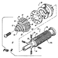
図1〜図6を参照して、本発明の好ましい実施形態に従って組み立てられ、参照数字10によって概して指定される棘突起間インプラントが図示される。インプラント10は、特に、例えば、棘突起間減圧(IPD)を含む、脊髄の狭窄を治療するための最小限の侵襲性の外科的処置の実施における使用に良く適応する。
With reference to FIGS. 1-6, an interspinous process implant, generally designated by
予測ではあるが、本発明のインプラント10は、脊椎融合処置の付属または脊椎安定デバイスとして、を含むが限定されない他の脊髄処置でも同様に使用され得る。当業者は、本発明の棘突起間インプラントは、経皮的に挿入によく適応し、それ故に、IPD処置での使用される当技術分野のデバイスの多くの欠点を克服するということを、次の説明から容易に理解するだろう。すなわち、インプラント10は、本明細書の下記で詳細に説明されるように、組織の切断を含む切開的外科処置というよりはむしろ、小さな切り口を通す導入および配置のために寸法決定され、構成される。
As expected, the
棘突起間インプラント10は、固体要素として構成され得るか、代替えとして、少なくとも部分的に中空であり得、脱塩された骨または別の種類の骨形成促進物質または融合付属材料の挿入を可能にするための複数の長手方向の開口14を含み得、また骨の内部成長も促進する、細長い螺子山で連結される本体部分12を含む。インプラント10は、本体部分12の遠位端で結合される、テーパーまたは円錐のヘッド部分16をさらに含む。ヘッド部分16は、インプラント10が、2つの隣接する棘突起381aおよび381bの、その間に進められる際に、進行的に開離するように寸法決定され、構成され得る。理解されているだろうが、ヘッド部分16は、開離が分離器具によって最初に実施される際、インプラントの挿入を容易にする。長尺本体部分12は、本発明の代替えの態様に従って、代替えとして、螺子山なしで提供され得るということも理解される。
The
本明細書で明記される他の実施形態で、ヘッド部分16は、インプラントの長手方向の軸に関連して、約5度と約65度との間の角度で、軸方向内向きに先細になる。本発明の1つの態様に従って、この角度は約15度と約45度との間の角度である。本発明の別の態様に従って、この角度は約25度と約35度との間の角度である。さらに別の態様に従って、この角度は約30度である。理解されているだろうが、この角度は上述の範囲に限定されない。
In other embodiments specified herein, the
ヘッド部分16は、機械締結器具、機械連結器具または溶接等のいずれの好適な方法において、体部に付着され得る。図示される実施形態において、例えば、内部螺合が提供されているが、軸方向のねじ要素が提供される。
The
インプラント10のテーパーヘッド16は、追従スカート区分18として構成される遠位アンカー部分を含む。具体化されるように、スカート区分18は、円周方向に離間する複数のプリーツ20から形成される動的構造である。プリーツ20はヒンジで連結され、略弓形構成であり得る。ヒンジ連結は、「リビングヒンジ」を形成するように、その材料の画定された弱線によって達成されてもよく、または代替えとして、別個の枢軸を備える従来のヒンジであってもよい。代替えとして、さらにプリーツ20の必要偏差は、プリーツ20の、それらの長さに沿う繰り返しの屈曲を使用してのみ、画定した線なしで達成され得る。さらに、プリーツ20は、弓形構成を有するもの以外の、例えば、略長方形の平行六面体等の形で、具体化されてもよい。
The tapered
1つの好ましい態様に従って、ヘッド部分16および追従スカート区分18は、2つの隣接する骨棘突起381aと381bとの間の、それらを通る挿入の間に、ヘッド部分16およびスカート区分18の漸進的な前進を、容易にするように、らせん状の螺子山22を有する。挿入の間に回転力が加えられると、螺子山22は、インプラント10を、隣接する棘突起381a、381bによって画定される、標的棘突起間の間隙382へ引き込むような役目を果たす。らせん状の螺子山22は、例えば、切断螺子山または箱型螺子山等のいずれの好適な形状にもなり得るということが予測される。しかしながら、テーパーヘッド部分16およびスカート区分18は、いずれの螺子山なしに提供され得るということも予測され、十分に主題開示の範囲内である。さらに、一体タップ溝は、螺子山に組み込まれ得、望ましい場合、螺子山が提供されず、インプラント10のヘッド部分16が、略軸方向に方向付けられる力の適用によって、2つの隣接する棘突起381aおよび381bの間を進められ得る、実施形態であり得る。
In accordance with one preferred embodiment, the
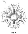
図6で明白なように、スカート区分18の弓形プリーツ20のそれぞれは、コイルの付勢ばね25によって、図1で示される、放射状に拡張した状態に付勢される。コイルの付勢ばね25は、ヘッド28によって本体部分12に保有されるガイドピン26で支持される。ガイドピン26のヘッド28は、スカート区分18の弓形プリーツ20が延長し得る範囲を限定するような働きをしない。代替え的な付勢機構は、プリーツ20を拡張した状態に付勢するために使用され得、エラストマー等の弾性材料の供給を含むが、限定されないということが予測される。例えば、そのような材料は生物学的に適合したシリコンであり得る。下記に詳細に説明されるように、プリーツ20は、図1〜図3および図5に示される拡張した状態と、例えば図4に示される(2番目の)放射状に圧迫された状態との間を運動するように適合され、構成され得る。望ましい場合、シース(図示されない)は、生物学的に適合したエラストマーの薄い層として、プリーツ間の柔軟性を可能にする一方で連続表面を維持するために、ヘッド部分16の構造上に提供され得る。代替えとして、ウェブまたは類似の要素が、隣接するプリーツ20間に提供され得る。
As can be seen in FIG. 6, each of the
インプラントデバイス10はさらに、ヘッド部分16(例えば図3)から離間する第1の位置と、ヘッド部分16(例えば図5)に接近する第2の位置の間の体長12に沿うアンカー部分30の長手方向移動を可能にするような方法で、螺子山で連結される本体12に動作可能に結合される、近位アンカー部分30をさらに含む。本体部分12と近位アンカー30との間の動作接続は、近位アンカー30と本体12との間の直接的な螺子山による接続、または、近位アンカー30が、本体部分12の軸の周囲で回転することなしに、1つ以上のインターフェース平面領域17a、17bを提供する事等によって、螺子山で連結される本体部分12に沿って長手方向に移動させることを可能にする、捕捉した螺子山で連結される本体部分ナットの使用を含む、様々な方法で達成され得る、ということが予測される。
The
図1〜図6を参照して、ヘッド部分16およびアンカー部分30が、棘突起381aおよび381bの周囲に互いに接近する際に、追従スカート区分18の弓形プリーツ20の近位表面は、棘突起381aおよび381bの骨生体構造に係合するように適合され、構成される近位に方向付けられたスパイク24を備え得る。同様に、遠位アンカー30の表面は、ヘッド部分16およびアンカー部分30が互いに図5に示される位置に接近する際に、骨棘突起381aおよび381bを係合するために、円周方向に離間して遠位で対向する複数のスパイク34を含み得る。本発明のいずれの実施形態に関連して、本明細書で説明される、スパイク34またはいずれのスパイクもいずれの特定の形に限定されないが、例えば、略円錐、ピラミッド形または四面体であり得る。代替えとして、スパイクは、そのような形の切頂型であり得る。
1-6, as the
使用において、ヘッド部分16は、図4で示されるように、2つの隣接する棘突起381aおよび381bとの間に挿入され、スカート区分18のプリーツ20は、コイルのスプリンング25の付勢または代替えの付勢要素に対して、圧迫された状態に促される、本発明に従って、プリーツ20は、必要であれば、本体12の直径を越えて延長しないように圧迫され得る。スカート区分18が一度開離した棘突起381a、381bを越えると、プリーツ20は、ばね25の付勢下でそれらの通常の拡張した位置へ戻すように促される。インプラント10は、代替えとして、インプラント10が、その挿入の間に開離を引き起こすことは必ずしも必要ではないが、むしろ、開離を維持することが必要とされる場合、タップまたは開離物等の他の分離器具の次に続く挿入物を挿入し得る。
In use, the
本発明の別の態様に従って、ヘッド部分16が提供され、つぶれた状態で挿入され、インプラント10が所望の位置に配置されると拡張され得る。ヘッド部分16の拡張は、下記に説明される実施形態に関連して説明されるように、内部カム機構によって達成され得る。そのような手はずで、外向きに付勢する部材は、例えば、ガイドピン26のヘッド28が内部可動カムに追随する間に、取り除かれ得る。ヘッド部分16単体の構造が、ヘッド部分16のつぶれた状態を維持するために十分でない場合、内向きに付勢する要素(例えば、本体12内のばね配置)を本体12とピンヘッド28との間に提供するような手はずが望ましい可能性がある。当業者は、本発明に従って組み立てられるいずれのインプラントも、通常展開した状態または通常つぶれた状態で提供され得るということを理解するであろう。
In accordance with another aspect of the present invention, the
その後、近位アンカー30は、図5で示されるように、ヘッド部分16の接近位置に移動される。一度接近すると、プリーツ20から構成される遠位アンカーを有するヘッド部分16、その間の棘突起381aならびに381bの圧迫する近位アンカー30、およびそれぞれの構成要素上のスパイク24、34は、意図的でない移行に対して、インプラント10を固定する。もたらされた組み立ては、同時に、本体部分12がそれぞれの隣接する椎骨間の組織を円圧するために、棘突起381aおよび381bの間でスペーサーとして働く一方で、標的棘突起間の間隙382の棘突起381a、381bを安定させるための役目を果たす。
The
本明細書で説明される他の実施形態のいずれにおいても、本体部分12は、次の寸法を備えるが、それらに限定されない。本体部分12は、症状を示す円板の高さの棘突起の間の螺子山による連結の配置のために寸法決定され、構成される。これに関して、インプラント10の外側直径は、約1.0mmの深さの螺子山を備えて、約8.0mm〜約16.00mmの範囲であり得るということが予測される。インプラント10の本体部分12上の螺子山は、下記に説明されるように、棘突起間の間隙の中へのインプラントの挿入を容易にするために、インプラントがセルフタッピング式であるように構成され得る。上述のように、インプラント10は、本発明に従ういずれのインプラントにおいても、望ましいか、必要とされるように、螺子山を備えるか、螺子山なしに提供され得る。
In any of the other embodiments described herein, the
インプラント10の構成要素または、本明細書に従って組み立てられるいずれのインプラントも、互いに類似または同一の材料から形成され得る。例えば、望ましいか、必要とされる場合、PEEK、ニチノール等のチタン合金または形状記憶合金等の合金、セラミック、および/または複合材料等の重合体を使用し得る。しかしながら、インプラント10の構成要素は、互いに異なる材料から形成され得るということが、特に予測される。例えば、本体12は、ヘッド部分が、ニチノール等のチタン合金または形状記憶合金等の合金から形成される一方で、PEEK等の重合体材料から形成され得る。セラミックおよび/または合成材料は、望ましいか必要とされる場合、付加的または代替的に使用され得る。
The components of the
図7〜図13を参照して、参照数字100で概して指定される、本発明のインプラントの別の実施形態が図示されている。インプラント100は、細長い螺子山で連結される本体部分112、本体部分112の遠位端のテーパーヘッド部分116および、ヘッド部分116から離間する第1の部分と、ヘッド部分116に接近する第2の位置との間の、本体部分112の長さに沿う長手方向移動に適合される近位アンカー部分130を含む、前記に説明されたインプラント10と類似する。
With reference to FIGS. 7-13, another embodiment of the implant of the present invention, generally designated by the
インプラント100は、その遠位端部分が隣接する生体構造(棘突起381a、381b)に係合する方法において、インプラント10と異なる。1つの態様に従って、遠位アンカー部分として、複数の外向きに付勢されるプリーツ20を有する代わりに、ヘッド部分116は、インプラント100の穴150内に、枢軸リング123の周囲の枢軸運動のために装着される、円周方向に離間する展開可能なブレード120を含む。特に、ブレード120は、ヘッド部分116内で後退される、図7に示される第1の収容した位置と、ヘッド部分116から外向きに放射状に突出する、図8に示される第2の展開した位置との間の運動のために装着される。インプラント110の本体部分112は、提供される、それぞれのブレード120に対応して、隙間115を備える。
The
後退した位置と展開した位置との間のブレード120の運動は、内部プランジャー126の作動を通して、部分的に達成される。より具体的には、プランジャー126のヘッド128の表面は、カムとして働き、それぞれのブレード120上に形成される、内側カム表面140に連携する。プランジャーのヘッド128が、遠位に移動する場合、ブレード120のカム表面140は、プランジャーのヘッド128の外側表面に追随し、ブレード120を放射状に外向きに促す。
Movement of the
例えば1、2、3、4、5、6、7、8、9、または10個のブレード120を含むが限定されない、いずれの実施可能な数量も提供され得るということは理解されているだろうが、図示されるように、4つの直交ブレード120が提供される。
It will be appreciated that any feasible quantity may be provided including, but not limited to, for example, 1, 2, 3, 4, 5, 6, 7, 8, 9, or 10
ブレード120およびそれらの環状枢軸リング123は互いに本体112の穴150内に接続される、それ故にサブアセンブリ119を形成する。サブアセンブリ119は、インプラント100の長手方向の軸に沿う軸方向に固定された配置に提供されるか、代替えとして、サブアセンブリ119の制限された軸方向の運動を可能にするように構成され得る。
The
1つの態様において、ブレード120は順に、穴150の内壁152に位置的に強制される、枢軸リング123にかみ合されるか、代替えとして、一体的に穴150の内壁152で形成される。壁152に対する枢軸リング123の軸位置の固定は、いずれの好適な方法においても容易にされ、的確な材料の選択次第であり得る。機械的な接続は、例えば、スナップまたはその圧入を可能にするために使用され得る。例えば、1つ以上の突起の形状の止め具、または代替えとして、溝154が、穴150に提供され得る。そのような特性で、枢軸リング123は、捕捉され、その軸位置は固定される。この観点で、枢軸リング123は、「分裂リング」として構成され得るか、さもなければ周囲に圧迫可能な部材として構成され得る。このように、サブアセンブリ119は、穴150を通して、本体112の近位端117から軸方向に挿入され、インプラント100の遠位端に向かって移動され得る。そのような係合は、的確な履行次第で、その的確な永続的または一時的のどちらかであり得る。代替えまたは付加的に、永続的な位置を達成するため、リング123は、溶接等によって、穴150の内壁152に永続的に付着し得、互換性のある材料が使用されることを提供され得る。
In one aspect, the
サブアセンブリ119の再位置決め可能な性能が望ましい場合、突起および/または溝の相対的な大きさおよび構成は、枢軸リング123は、そのような特性(例えば、溝154)によって、解放可能に捕捉され、十分な力の適用によって、それから除去され得るようになり得る。この観点において、枢軸リング123は、使用される素材次第で、弾性または剛性(すなわち、ばね割合)および摩擦特質等を含む、固有の機械的特質を含む。適切に寸法決定され、履行される場合、ブレード120および枢軸リング123を含む、サブアセンブリ119は、そのような特性の方法で、いずれの段階においても軸方向に位置され得る。
If the repositionable performance of the subassembly 119 is desired, the relative size and configuration of the protrusions and / or grooves may cause the
図7で示されるように、ブレード120は、インプラント100の配置の前に収容され得る。挿入過程を妨害し得る、枢軸リング123の周囲のブレード120の意図されない旋回を阻止するため、サブアセンブリ119の収容した構成は、隙間115を通して、その放射状外側の末端132が内向きに回転し、インプラント100の穴150へ入ることを可能にし得る。サブアセンブリ119は、ブレード120を、穴150内に完全にもたらし、穴150内の放射状外側の末端132を捕捉しながら、次に近位に移動され得る。例えば、溝(例えば154)等の位置特性は、収容した位置に対応し、ブレード120の展開が望まれるまで、サブアセンブリ119の軸位置を維持し得る。その際、プランジャー126は、ブレード120が枢軸リング123の周囲で、隙間115を通して、自由に回転する、軸位置にサブアセンブリ119を押しながら、遠位に促され、上記に説明されるように、それはブレード120のカム表面140に関連して、プランジャー126の運動によって達成され得る。
As shown in FIG. 7, the
任意で、サブアセンブリ119は、穴150の内側末端面152についてブレード120の外側表面を位置する場所で、穴150の遠位端に軸方向に移動するように構成され得る。そのような位置づけは、それらが標的棘突起381a、381b(例えば図10〜図13)に係合するように構成される、ブレード120が展開した位置からの反転または過剰外延を有利に阻止する。
Optionally, subassembly 119 may be configured to move axially to the distal end of
ブレード120のサブアセンブリ119および枢軸リング123が軸方向に移動可能である構成において、プランジャー126のヘッド128は、枢軸リング123の内側直径よりも大きい外側直径で作られ得、そのため、プランジャー126の作動は、ブレード120の外向きの回転に続いて、放射状に、単純にそれを押すことによって、サブアセンブリ119の遠位軸方向の移動を生じさせる。
In configurations where the subassembly 119 of the
本発明に従って、枢軸リング123の代わりに1つ以上の線枢軸が提供され得る。そのような線枢軸は、本体112に固定されるか、もしくはそこを通って固定される定置要素として提供されてもよく、または代替えとして、本体112に対する、軸方向の運動のために装着されてもよい。そのような線枢軸は、本体112に対して、接線方向または横方向に装着されるか、中心装着され得る(例えば本体112の長手方向の軸に横に交差する)。
In accordance with the present invention, one or more pivot axes may be provided instead of the
プランジャー126自体は、その作動およびその位置の固定を可能にする特性を含む、様々な特性を備え得る。例えば、図9で最も図示されるように、遠位円形ヘッド128に加えて、プランジャー126は、近位方向から加えられる、遠位に方向づけられる促しおよび近位に方向づけられる促しのそれぞれを容易にするために、近位内部の凹所121および傾斜した遠位表面を有する近位ヘッド125を含み得る。プランジャー126は、弾力性の留め金127に固定的に係合するために、凹所129をも含み得る。留め金127は、環状溝または凹所等の本体112のプランジャー126と内部表面特性との間を接合するように構成される。説明されるように、弾力性の留め金127は、プランジャー126の軸方向の運動を可能にし、そこからの意図的でない運動を阻止しながら、プランジャー126が保持される場所に位置を画定される、上記に説明される、本体112の内部表面の特性に連動する。留め金127は、例えば、エラストマー等の弾力性の材料等から、またはトロイダル金属コイル等の弾力性の構造から、または図示される実施形態において、図9、図12および図13で明白なように、プランジャー126は、エラストマー材料で外側被覆される、これらの組み合わせ等のいずれの好適な材料または構成からも形成され得る。後続の実施形態において、さらに別々の要素が提供され、その構成は本実施形態に等しく加えられ得る。
The plunger 126 itself may have various characteristics, including characteristics that allow its actuation and its position to be fixed. For example, as best illustrated in FIG. 9, in addition to the distal
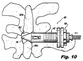
図7から図13で示されるように、インプラント100は、近位アンカー130の遠位表面が、標的棘突起間の間隙382に隣接する、棘突起381a、381b(図10〜図13)の1つの側面に係合するために、遠位で対向する複数のスパイク134を含み得る点で、インプラント10にも類似している。類似の形状で、近位に対向するブレード120の対向表面は、棘突起381a、381bの他の側面に係合するために、スパイク124に備え付けられ得る。
As shown in FIGS. 7-13, the
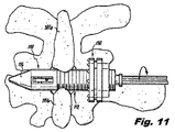
図10〜図13は、インプラント100の挿入の間の様々な段階および配置を図示する。図10は、標的棘突起間の間隙382への導入の間のインプラント100を図示する、背面(後面)図である。図11は、遠位アンカー要素またはブレード120が、その展開を可能にしながら、生体構造に妨げられない位置まで進められる、取り付けの間のインプラント100を図示する、インプラント100の背面図である。図12は、展開された状態の遠位アンカー120の要素を備える、取り付けの間のインプラント100を図示する、インプラント100の背面図である。図13は、遠位に促される近位アンカー130を備える、隣接する棘突起381a、381bとインプラント100の係合を引き起こしている、インプラント100を図示する、インプラント100の背面図である。
10-13 illustrate various stages and arrangements during insertion of the
本発明に従って、図1〜図6の実施形態に関連して上記に説明されるように、インプラント100は、既に展開され、本体112から外向きに向かって延長しているブレード120を備える、標的棘突起間の間隙382に挿入され得る。例えば、そのような適用において、ブランジャー126は、ブレード120が展開される遠位位置に配置される。プランジャー126は、部分的に延長した(中間)位置に配置され得る。部分的に延長した位置において、ブレード120の放射状内向きの促しは、ブランジャー126の近位の促しを引き起こす。プランジャー126は、そのため、止め具または遠位または中間位置に付勢されるばねを備え得る。遠位にばね付勢される場合、プランジャー126は、一度それらが妨害から自由になった時点で、外向きにブレード120を促すことを試みる。さらに代替えとして、インプラント100は、枢軸リング123または他の枢軸の手はずが、その完全に延長した位置でのプランジャー126の位置にかかわらず、ブレード120の内向きの促しを可能にするように、具体化され得る。そのような手はずにおいて、枢軸リング123が、ブレード120の末端132が内向きに移動することを可能にするために曲がる際に、ブレード120はプランジャー126のヘッド128の周囲に旋回する。
In accordance with the present invention, the
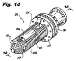
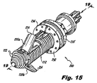
図14〜図24は、本発明のさらなる態様に従う棘突起間インプラント200を図示する。インプラント200は、類似の要素が上記に使用される類似の参照の数で指定される際に、上述の実施形態のいくらかの特性を含む。インプラント200は、インプラント200に全体の構造を提供する本体212を含む。本体212は図示され、図20〜図24に関連して下記に詳細に説明されるように、標的棘突起間の間隙382で患者の生体構造に付加的な係合を提供すると同様に、標的棘突起間の間隙へのインプラント200の挿入を容易にするために、螺子山222を備える(図20〜図24)。さらに、固定的にインプラント200と標的棘突起間の間隙382に隣接する、棘突起間381a、381bとの係合を提供する、螺子山222は、本体212と近位ナット235との間の回転的係合を可能にし、下記に詳細に示される。代替えとして、このインプラント200および本発明の他のインプラント10、100は、それ上に螺子山なしで提供され得るか、上述の機能の1つのためにその部分上にのみ提供される螺子山を備えて提供され得る。すなわち、望ましい場合、螺子山222は、ナット235を係合するために、本体112の遠位部分上でなく近位端上のみで、または逆も同様に、提供され得る。
14-24 illustrate an
上述の実施形態に関して、遠位アンカー部分は提供され、本実施形態は、2つの対向する展開可能なブレード220(220a、220b)として構成される。ブレード220は、本体212を通ることと同様に、その中を通過するピン259によって画定される共通の軸を備える。本的確な構成からの変化は可能であるが、共通の枢軸の使用は、収容した状態で本体212内の全ての要素を収容するために、必要とされる間隙を有利に最小化する。例えば、さらに本発明に沿って、2つの分離軸は、220a、220bのブレードのそれぞれに提供され得る。図示されるように、ブレード220は、棘突起381a、381b等の関連する隣接する骨生体構造に係合するために近位に対向するスパイク224を備える。ブレード220は、代替えとして、そのようなスパイク224なしで提供され得る。
With respect to the embodiments described above, a distal anchor portion is provided, which is configured as two opposing deployable blades 220 (220a, 220b). The blade 220 includes a common axis defined by a
ブレード220a、220bは、ピン259に係合するために、ヒンジ部分223a、223bをそれぞれ備える。図示される実施形態において、1つのヒンジ部分223aは、U字型に成形され、一方で、他の223bは、U字型成形のヒンジ部分223a内でかみ合うように成形される。
図示される実施形態において、プランジャー226は、上記に説明されるように、カムとして働くように成形され、構成され、ブレード220a、220bのそれぞれの上に形成される、内側のカム表面240に連携される、ヘッド部分228を提供され、含む。プランジャーヘッド228が遠位に移動する際、ブレード220a、220bのカム表面240は、プランジャーヘッド228の外側表面に追随し、放射状に外向きにブレード220a、220bを促す。加えて、プランジャーは、上記に説明されるように、近位方向から加えられる、遠位に方向づけられる促しおよび近位に方向づけられる促しのそれぞれ容易にするために、近位内部の凹所221および傾斜した遠位表面を有する、近位ヘッド225を含み得る。プランジャー226は、弾力性の留め金227に固定的に係合するために、凹所229をも含み得る。留め金227は、環状溝または凹所254等の本体212のプランジャー226と内部表面特性との間を接合するように構成される。説明されるように、弾力性の留め金227は、プランジャー226の軸運動を可能にし、そこからの意図的でない運動を阻止しながら、プランジャー226が保持される場所に位置を画定される、上記に説明される、本体212の内部表面の特性に連動する。留め金227は、例えば、エラストマー等の弾力性の材料等から、またはトロイダル金属コイル等の弾力性の構造から、またはこれらの組み合わせ等のいずれの好適な材料または構成からも形成され得る。留め金227は、本発明に従って、Foothill Ranch CaliforniaのBal Seal Engineering,Incから入手可能な、Bal Latch(登録商標)等の斜め巻きコイルであり得る。
In the illustrated embodiment, the
展開した際、ブレード220は、インプラント200の長さに沿って軸方向に移動可能な近位アンカー部分230に呼応して、機能する。ナット235は、本体212の外側表面に提供される螺子山222に係合する、その内側表面上に螺子山を含む。したがって、ナット235の回転運動は、その軸運動を生じさせる。その軸運動が遠位方向にある場合、ナット235は、標的棘突起間の間隙382を囲む、骨構造(例えば、棘突起381a、381b)に隣接するまで、遠位に近位アンカー部分230を促す。提供される場合、近位アンカー部分上の突起またはスパイク234は、骨との係合、それ故に、全体の椎骨インプラントの組み立ての安定化を容易にする。
When deployed, the blade 220 functions in response to a
図示されるように、上部および下部平面部分217a、217bをそれぞれ備える、平面部対向平面部分217は、ナット235の運動の間に、軸運動を可能にし、その回転運動を阻止しながら、近位アンカー230の、対応して成形された(例えば、平面)部分237を導く。止めワッシャ233または同等の特性は、ブレード220a、220bの移植および展開に続くナット235の意図的でない弛緩を阻止するために提供され得る。
As shown, the planar opposing planar portion 217, comprising upper and lower
図18〜図19の断面図を参照に、図示される実施形態において、ブレード220は、ブレード220a、220bのそれぞれの各凹所の間にわたる、内部ばね要素281を備え得る。ばね要素281は、通常、展開される(開く)ブレード220a、220bを維持するために真っ直ぐな状態か、代替えとして、通常、収容される(収縮される)、ブレード220a、220bを維持するために曲げられた状態で提供され得る。1つの態様に従って、ばね要素281は、曲げられた状態で提供され、移植前および移植の間に、収容された位置に向かって、内向きにブレード220a、220bを促す。それ故に、プランジャー226に関連して、ばね281は、ブレード220の位置を維持するように役目を果たす。図示されるように、プランジャー226は、完全に延長され、そのヘッド部分228は、ブレード220a、220bの側面240で、対応する戻り止め249に係合する。ヘッド部分228による戻り止めの係合は、さらに、ブレード220a、220bの固定した展開を確かにする。
With reference to the cross-sectional views of FIGS. 18-19, in the illustrated embodiment, the blade 220 may include an
本発明に従って、ばね要素281は、代替えとして、移植前、移植の間および移植後に展開される位置に向かって、外向きにブレード220a、220bを促しながら、通常真っ直ぐな状態として、提供され得る。移植の間、しかしながら、ばね要素281は、過程でばね要素281を一時的に曲げながら、ブレード220a、220bの内向きの回転を可能にする。それ故に、移植の間、ばね281は、外部から加えられる力に対して、ブレード220a、220bの位置を維持するような役目を果たす。標的棘突起間の間隙382に一度配置されると、プランジャー226は、展開した位置でブレード220a、220bを係止するために遠位に促され得る。プランジャー226のヘッド部分228による戻り止め249の係合は、さらに、その位置の維持を確かにする。本体212は、その近位端に、ナット235の移動のための近位の最大限度を画定する、拡張した直径部分213、および近位アンカー230を含む。近位端部分にはまた、穴250内に形成される、挿入用具での係合のために、成形されたソケット251がある。図示されるように、ソケット251は、一定の角度間隔で画定される平面部分を備え、実質的に六角形である。図示される的確な構成からの実施可能な逸脱は可能である。成形されたソケット251は、インプラント200と挿入用具との間の相互の回転係合を容易にする。またソケット251に関連して提供されるのは、挿入用具上で、対応する要素に連動して、その間の意図的でない相互の軸転位を阻止する、横断溝253である。挿入器具上の対応する要素は、例えば、挿入用具から側部に延長する(すなわち、放射状に)弾力性で、任意で係止可能な突起であり得る。例えば、係止可能な突起は、例えば、係止可能なばねを装荷した球状の要素であり得る。
In accordance with the present invention, the
上述の実施形態のように、インプラント200は、その穴250等で、骨内部成長および/または融合を容易にするための骨形成促進物質を備える、脱塩した骨内等の、インプラントの充填を可能にするために1つ以上の隙間214を備え得る。
As in the above-described embodiments, the
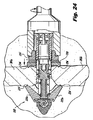
図20〜図24は、標的棘突起間の間隙382内へのインプラント200の挿入および配置の間の様々な段階を図示する。要するに、図20は、患者の皮膚388を通って形成される切り口389を通して挿入される、曲線状の導入チューブ387を背部に通して取り付けられることに備える、インプラント200の斜視図である。図21は、その側部挿入の間、導入チューブ397の管腔内で細長い挿入用具392を保持する、インプラント200の背面(後面)図である。図22は、その本体212上に提供される螺子山222の作用によって、挿入用具392によって加えられる回転力の適用下で、標的棘突起間の間隙382に対して側部に進む、インプラント200を図示する、背面図である。図23は、この場合の遠位アンカー要素である、ブレード220a、220bの展開を生じさせながら、遠位に促される内部プランジャー226を備える、インプラント200を図示する、背面図である。ナット235は、次に堅く締められ、隣接する棘突起281a、281bに係合しながら、ナット235によって遠位に促される、近位アンカー要素230を備える、インプラント200を図示する、背面図である、図24に示されるように、近位に本体212を促し、それ故にまた、その間の棘突起381a、381bの間に衝突しながら、隣接する骨構造に対してより固定的に、ブレード220を促す。
20-24 illustrate various steps during insertion and placement of the
より具体的には、図20に見られるように、スリーブ387は、挿入を容易にするように提供される。挿入方法は、下記により詳細に説明されるように、スリーブ387へのアクセスを増やし、経路を画定するために、探り針および拡張器等の使用を含み得る。しかしながら、背面挿入は、2008年1月30日に出願された米国特許出願第12/011,905号(米国特許出願第2009/0054988号)に明記されるように達成され得、参照によりその全体が本明細書に組み込まれる。
More specifically, as seen in FIG. 20, a
図20に図示されるように、インプラント10によって表される、対象インプラントの背面挿入は、隣接する脊椎の突起381aと381bとの間に画定される、標的棘突起間の間隙382に対応する高さ図1で、患者の皮膚388を通る切り口389によって達成され得る。
As illustrated in FIG. 20, the posterior insertion of the subject implant, represented by
図20に図示される背面進入で、インプラント200、故に、スリーブ387によっても横行される経路は、標的棘突起間の間隙382を備える経路およびインプラント200を整列するために曲線状である。
In the dorsal approach illustrated in FIG. 20, the path that is also traversed by the
対照的に、図21は、標的棘突起間の間隙382へのインプラント200の直接側部挿入を図示する。この適用において、切り口399が患者の肌388に形成され、最終的に、スリーブ397は、組織を通して、挿入デバイス392に接続される、インプラント200が進められることを通じて、標的棘突起間の間隙382へ、進められる。スリーブ397なしに明確に図示され、図22〜図24に示されるように、インプラント200は、挿入デバイス392によって軸方向に回転され、それ故に、インプラント200は標的棘突起間の間隙382を螺子山で連結し、隣接する棘突起381a、381bを開離し、インプラント200を、棘突起381a、381bに対して略中心である、その最終位置に進める。上記に明記されるように、開離は、インプラントの挿入に続き、開離を維持する、分離器具によって事前に実施され得る。インプラント200の回転の間、インプラント200と挿入デバイス392との間の相対的な回転および軸移動は、好ましくは、上記に述べられる特性によって阻止される。適切な位置にある際、固着ブレード220a、220bは、図23に示されるように展開され得る。ナット235は、次に、係止する近位アンカー230を、隣接する棘突起381a、381bの係合へ、遠位に進めながら、堅く締められ得る。
In contrast, FIG. 21 illustrates direct side insertion of the
次に、1つ以上の骨形成促進物質は、望ましい場合、骨内部成長および/または脊椎融合を促進するためにインプラント200で/または周りで充填され得る。
Next, one or more osteogenesis-promoting substances can be filled in / around the
分離タップは、インプラント200の挿入前に標的棘突起間の間隙382で使用され得るか、上記に述べられるように、インプラント200は、セルフタッピング機能を提供する特性を備え得る。
Separation taps can be used in the
標的棘突起間の間隙382への脊椎インプラント200の側部挿入の方法は、次に続く切り口399の形成すること、好ましくは、蛍光透視法等の内部撮像技術を使用して、切り口と標的棘突起間との間隙382に横方向に、切り口399を通して探り針を挿入すること(図示せず)を含み得る。
The method of lateral insertion of the
探り針の挿入は、切り口と標的棘突起間の間隙382との間の軟組織を拡張するために、1つ以上の拡張器が順に進められ得ることに従って、進入経路を形成する。スリーブ397は、次に、進入経路を通して進められ得る。スリーブ397を挿入した後、タップ(目盛り付きのタップ)であり得る開離物は、タッピングし、隣接する棘突起381a、381bを徐々に開離し、および/または挿入されるインプラントの適切な大きさの決定を助けるために、次に標的棘突起間の間隙382へ挿入され、進められ得る。
The insertion of the probe forms an access path according to which one or more dilators can be sequentially advanced to dilate the soft tissue between the incision and the
棘突起間の開離の所望の量に適切な大きさを有するインプラント200の選択の次に、デバイス392に保持されるインプラント200が挿入され、インプラント200が、標的棘突起間の間隙382へ挿入される後、標的棘突起間の間隙382までスリーブ397を通して進められ得る。螺子山による連結のインプラントの場合、回転運動は、インプラント200を進めるために加えられ、まだ開離されていない場合、隣接する棘突起381aおよび381bを開離するために加えられる。螺子山によって連結されないインプラントの場合、いずれの近位および/または遠位の係合要素が展開された後、側面に方向づけられる圧力は、インプラント300が所望の位置になるまで加えられ得る。
Following the selection of an
本明細書で説明される多くのインプラントデバイスの主な構造上の構成要素は、好ましくは、例えば、ポリエーテルエーテルケトン熱可塑性プラスチック(PEEK)、機械加工の骨、チタン合金またはステンレス鋼等の骨の弾性率に実質的に類似するものを有するために選択され得る、金属、セラミック、重合体、および/または複合材料を含む、生物学的および/または生物学的に互換性のある材料から形成される。 The main structural components of many implant devices described herein are preferably bones such as, for example, polyetheretherketone thermoplastic (PEEK), machined bone, titanium alloy or stainless steel Formed from biologically and / or biologically compatible materials, including metals, ceramics, polymers, and / or composites, which can be selected to have substantially similar modulus of elasticity Is done.
本発明の装置および方法が、好ましい実施形態を参照に、示され、説明される一方で、それに関連して明白に説明されていない場合も、当該の特性が当該の実施形態の他の特性に互いに排他的でない場合、1つの実施形態に関連して説明されるいずれの特性も、本発明の他の実施形態に有利に加えられ得るということが理解される。それにもかかわらず、当業者は、その精神および範囲から逸脱することなしに、本発明のデバイスおよび方法に対して、さらなる変更または修正がなされ得るということを容易に理解するだろう。 While the apparatus and method of the present invention have been shown and described with reference to preferred embodiments, such characteristics may differ from other characteristics of the embodiments even if not explicitly described in connection therewith. It will be understood that any feature described in connection with one embodiment may be advantageously added to other embodiments of the invention if not mutually exclusive. Nevertheless, those skilled in the art will readily appreciate that further changes or modifications may be made to the devices and methods of the present invention without departing from the spirit and scope thereof.
Claims (3)
b)前記長尺本体の遠位端に結合される、遠位アンカーと、
c)前記遠位アンカーから離間する第1の位置と前記遠位アンカーに接近する第2の位置との間で前記長尺本体に沿って長手方向に移動するように装着され、前記遠位アンカーに連動して前記2つの隣接する棘突起を圧迫するように適合される、近位アンカーと、
を含み、
前記長尺本体および前記近位アンカーが、前記第1の位置と前記第2の位置との間の、前記長尺本体に沿う前記近位アンカーの長手方向移動を容易にするために、相互に螺合される、脊椎インプラント。 a) an elongate body dimensioned and configured to function as a spacer for placement in a gap between two adjacent spinous processes, between the target spinous processes;
b) a distal anchor coupled to the distal end of the elongate body;
c) mounted to move longitudinally along the elongate body between a first position spaced from the distal anchor and a second position approaching the distal anchor; A proximal anchor adapted to compress the two adjacent spinous processes in conjunction with
Only including,
In order to facilitate longitudinal movement of the proximal anchor along the elongate body between the first position and the second position, the elongate body and the proximal anchor may be A spinal implant that is screwed together .
b)前記長尺本体の遠位端に結合される、遠位アンカーと、
c)前記遠位アンカーから離間する第1の位置と前記遠位アンカーに接近する第2の位置との間で前記長尺本体に沿って長手方向に移動するように装着され、前記遠位アンカーに連動して前記2つの隣接する棘突起を圧迫するように適合される、近位アンカーと、
を含み、
前記遠位アンカーが、テーパーヘッドを含み、前記テーパーヘッドが、その中立的状態で、前記長尺本体の直径より大きい最大直径を有し、かつ、前記遠位アンカーと前記近位アンカーとが互いに接近する際に、前記棘突起に係合するための、円周方向に離間して近位で対向する複数のスパイクを有し、
前記テーパーヘッドが、前記テーパーヘッドが前記2つの隣接する棘突起間に挿入される際に、放射状に拡張した状態と放射状に圧迫された状態との間を運動するように適合され、構成される、追従スカート区分を有する、脊椎インプラント。 a) an elongate body dimensioned and configured to function as a spacer for placement in a gap between two adjacent spinous processes, between the target spinous processes;
b) a distal anchor coupled to the distal end of the elongate body;
c) mounted to move longitudinally along the elongate body between a first position spaced from the distal anchor and a second position approaching the distal anchor; A proximal anchor adapted to compress the two adjacent spinous processes in conjunction with
Only including,
The distal anchor includes a tapered head, the tapered head having a maximum diameter in its neutral state that is greater than the diameter of the elongate body, and the distal anchor and the proximal anchor are A plurality of circumferentially spaced and proximally facing spikes for engaging the spinous processes when approaching;
The tapered head is adapted and configured to move between a radially expanded state and a radially compressed state when the tapered head is inserted between the two adjacent spinous processes. A spinal implant having a tracking skirt section .
b)前記長尺本体の遠位端に結合される、遠位アンカーと、
c)前記遠位アンカーから離間する第1の位置と前記遠位アンカーに接近する第2の位置との間で前記長尺本体に沿って長手方向に移動するように装着され、前記遠位アンカーに連動して前記2つの隣接する棘突起を圧迫するように適合される、近位アンカーと、
を含み、
前記遠位アンカーが、テーパーヘッドを含み、前記テーパーヘッドが、その中立的状態で、前記長尺本体の直径より大きい最大直径を有し、かつ、前記遠位アンカーと前記近位アンカーとが互いに接近する際に、前記棘突起に係合するための、円周方向に離間して近位で対向する複数のスパイクを有し、
前記テーパーヘッドが、前記テーパーヘッドが前記2つの隣接する棘突起間に挿入される際に、放射状に拡張した状態と放射状に圧迫された状態との間を運動するように適合され、構成される、追従スカート区分を有し、
前記テーパーヘッドの前記追従スカート区分が、前記放射状に拡張した状態に付勢される、円周方向に離間する複数のヒンジによって連結される複数のプリーツを含む、脊椎インプラント。 a) an elongate body dimensioned and configured to function as a spacer for placement in a gap between two adjacent spinous processes, between the target spinous processes;
b) a distal anchor coupled to the distal end of the elongate body;
c) mounted to move longitudinally along the elongate body between a first position spaced from the distal anchor and a second position approaching the distal anchor; A proximal anchor adapted to compress the two adjacent spinous processes in conjunction with
Only including,
The distal anchor includes a tapered head, the tapered head having a maximum diameter in its neutral state that is greater than the diameter of the elongate body, and the distal anchor and the proximal anchor are A plurality of circumferentially spaced and proximally facing spikes for engaging the spinous processes when approaching;
The tapered head is adapted and configured to move between a radially expanded state and a radially compressed state when the tapered head is inserted between the two adjacent spinous processes. , Has a tracking skirt segment,
A spinal implant wherein the tracking skirt section of the tapered head includes a plurality of pleats connected by a plurality of circumferentially spaced hinges biased to the radially expanded state .
Applications Claiming Priority (5)
| Application Number | Priority Date | Filing Date | Title |
|---|---|---|---|
| US20999709P | 2009-03-13 | 2009-03-13 | |
| US61/209,997 | 2009-03-13 | ||
| US12/554,922 | 2009-09-07 | ||
| US12/554,922 US8945184B2 (en) | 2009-03-13 | 2009-09-07 | Interspinous process implant and fusion cage spacer |
| PCT/US2009/006742 WO2010104496A1 (en) | 2009-03-13 | 2009-12-30 | Interspinous process implant and fusion cage spacer |
Publications (3)
| Publication Number | Publication Date |
|---|---|
| JP2012520120A JP2012520120A (en) | 2012-09-06 |
| JP2012520120A5 JP2012520120A5 (en) | 2013-01-24 |
| JP5548709B2 true JP5548709B2 (en) | 2014-07-16 |
Family
ID=41683475
Family Applications (1)
| Application Number | Title | Priority Date | Filing Date |
|---|---|---|---|
| JP2011554022A Active JP5548709B2 (en) | 2009-03-13 | 2009-12-30 | Interspinous implant and fusion cage spacer |
Country Status (12)
| Country | Link |
|---|---|
| US (3) | US8945184B2 (en) |
| EP (1) | EP2405836B1 (en) |
| JP (1) | JP5548709B2 (en) |
| KR (1) | KR101687977B1 (en) |
| CN (1) | CN102438536B (en) |
| AU (1) | AU2009341811B2 (en) |
| CA (1) | CA2755431C (en) |
| HK (1) | HK1170140A1 (en) |
| IL (2) | IL215006A (en) |
| MX (1) | MX2011009399A (en) |
| WO (1) | WO2010104496A1 (en) |
| ZA (1) | ZA201106825B (en) |
Families Citing this family (86)
| Publication number | Priority date | Publication date | Assignee | Title |
|---|---|---|---|---|
| US8128662B2 (en) | 2004-10-20 | 2012-03-06 | Vertiflex, Inc. | Minimally invasive tooling for delivery of interspinous spacer |
| US8152837B2 (en) | 2004-10-20 | 2012-04-10 | The Board Of Trustees Of The Leland Stanford Junior University | Systems and methods for posterior dynamic stabilization of the spine |
| US8425559B2 (en) | 2004-10-20 | 2013-04-23 | Vertiflex, Inc. | Systems and methods for posterior dynamic stabilization of the spine |
| US8409282B2 (en) | 2004-10-20 | 2013-04-02 | Vertiflex, Inc. | Systems and methods for posterior dynamic stabilization of the spine |
| US8167944B2 (en) | 2004-10-20 | 2012-05-01 | The Board Of Trustees Of The Leland Stanford Junior University | Systems and methods for posterior dynamic stabilization of the spine |
| US8273108B2 (en) | 2004-10-20 | 2012-09-25 | Vertiflex, Inc. | Interspinous spacer |
| US8123807B2 (en) | 2004-10-20 | 2012-02-28 | Vertiflex, Inc. | Systems and methods for posterior dynamic stabilization of the spine |
| US8317864B2 (en) | 2004-10-20 | 2012-11-27 | The Board Of Trustees Of The Leland Stanford Junior University | Systems and methods for posterior dynamic stabilization of the spine |
| US9023084B2 (en) | 2004-10-20 | 2015-05-05 | The Board Of Trustees Of The Leland Stanford Junior University | Systems and methods for stabilizing the motion or adjusting the position of the spine |
| US9161783B2 (en) | 2004-10-20 | 2015-10-20 | Vertiflex, Inc. | Interspinous spacer |
| US7763074B2 (en) | 2004-10-20 | 2010-07-27 | The Board Of Trustees Of The Leland Stanford Junior University | Systems and methods for posterior dynamic stabilization of the spine |
| US9119680B2 (en) | 2004-10-20 | 2015-09-01 | Vertiflex, Inc. | Interspinous spacer |
| WO2006058221A2 (en) | 2004-11-24 | 2006-06-01 | Abdou Samy M | Devices and methods for inter-vertebral orthopedic device placement |
| CA2701050A1 (en) | 2004-12-06 | 2009-07-09 | Vertiflex, Inc. | Spacer insertion instrument |
| US8845726B2 (en) | 2006-10-18 | 2014-09-30 | Vertiflex, Inc. | Dilator |
| CA2684461C (en) * | 2007-04-16 | 2015-06-30 | Vertiflex Inc. | Interspinous spacer |
| WO2014106246A1 (en) * | 2012-12-31 | 2014-07-03 | Lanx, Inc. | Interspinous implants with deployable wing |
| EP2244670B1 (en) | 2008-01-15 | 2017-09-13 | Vertiflex, Inc. | Interspinous spacer |
| US8192466B2 (en) * | 2008-08-27 | 2012-06-05 | Alphatec Spine, Inc. | Conical interspinous apparatus and a method of performing interspinous distraction |
| US9757164B2 (en) * | 2013-01-07 | 2017-09-12 | Spinal Simplicity Llc | Interspinous process implant having deployable anchor blades |
| US8945184B2 (en) * | 2009-03-13 | 2015-02-03 | Spinal Simplicity Llc. | Interspinous process implant and fusion cage spacer |
| US9861399B2 (en) | 2009-03-13 | 2018-01-09 | Spinal Simplicity, Llc | Interspinous process implant having a body with a removable end portion |
| US9179944B2 (en) * | 2009-09-11 | 2015-11-10 | Globus Medical, Inc. | Spinous process fusion devices |
| RU2012123373A (en) * | 2009-11-06 | 2013-12-20 | Зинтес Гмбх | MINIMALLY INVASIVE INTERBED SPACERS (IMPLANTS) AND METHODS |
| US8795335B1 (en) | 2009-11-06 | 2014-08-05 | Samy Abdou | Spinal fixation devices and methods of use |
| US8764806B2 (en) | 2009-12-07 | 2014-07-01 | Samy Abdou | Devices and methods for minimally invasive spinal stabilization and instrumentation |
| EP2512357B1 (en) | 2009-12-15 | 2016-07-13 | Vertiflex, Inc. | Spinal spacer for cervical and other vertebra, and associated systems |
| US9101409B2 (en) * | 2010-03-09 | 2015-08-11 | National University Corporation Kobe University | Inter-spinous process implant |
| AU2011302092A1 (en) * | 2010-09-14 | 2013-04-11 | Joule Unlimited Technologies, Inc. | Methods and compositions for the extracellular transport of biosynthetic hydrocarbons and other molecules |
| WO2012040477A2 (en) * | 2010-09-23 | 2012-03-29 | Alphatec Spine, Inc. | Clamping interspinous spacer apparatus and methods of use |
| US8876866B2 (en) | 2010-12-13 | 2014-11-04 | Globus Medical, Inc. | Spinous process fusion devices and methods thereof |
| US8906092B2 (en) * | 2011-01-24 | 2014-12-09 | Samy Abdou | Spinous process fixation devices and methods of use |
| US20120215262A1 (en) * | 2011-02-16 | 2012-08-23 | Interventional Spine, Inc. | Spinous process spacer and implantation procedure |
| US9149306B2 (en) | 2011-06-21 | 2015-10-06 | Seaspine, Inc. | Spinous process device |
| US8845728B1 (en) | 2011-09-23 | 2014-09-30 | Samy Abdou | Spinal fixation devices and methods of use |
| WO2013052496A2 (en) | 2011-10-03 | 2013-04-11 | In Queue Innovations, Llc | Interspinous process fusion device and method of use |
| EP2779925B1 (en) * | 2011-11-17 | 2019-01-16 | Howmedica Osteonics Corp. | Interspinous spacers |
| US20130226240A1 (en) | 2012-02-22 | 2013-08-29 | Samy Abdou | Spinous process fixation devices and methods of use |
| US9693876B1 (en) | 2012-03-30 | 2017-07-04 | Ali H. MESIWALA | Spinal fusion implant and related methods |
| US9198767B2 (en) | 2012-08-28 | 2015-12-01 | Samy Abdou | Devices and methods for spinal stabilization and instrumentation |
| US9320617B2 (en) | 2012-10-22 | 2016-04-26 | Cogent Spine, LLC | Devices and methods for spinal stabilization and instrumentation |
| WO2014145529A2 (en) * | 2013-03-15 | 2014-09-18 | 4-Web, Inc. | Traumatic bone fracture repair systems and methods |
| US9675303B2 (en) | 2013-03-15 | 2017-06-13 | Vertiflex, Inc. | Visualization systems, instruments and methods of using the same in spinal decompression procedures |
| CN104116579B (en) * | 2013-04-28 | 2016-08-03 | 苏州海欧斯医疗器械有限公司 | Implantation unit is strutted between a kind of Via Posterior Spinal Approach ridge |
| CA2913463A1 (en) * | 2013-05-29 | 2014-12-04 | Spinal Simplicity Llc | Instrument for inserting an interspinous process implant |
| US11801075B2 (en) * | 2013-05-29 | 2023-10-31 | Spinal Simplicity, Llc | Instrument for inserting an interspinous process implant |
| CN103431902B (en) * | 2013-08-30 | 2015-05-06 | 常州鼎健医疗器械有限公司 | Vertebral body fusion device |
| ES2671145T3 (en) | 2014-03-26 | 2018-06-05 | Medacta International Sa | Device for implanting a surgical screw |
| US10524772B2 (en) | 2014-05-07 | 2020-01-07 | Vertiflex, Inc. | Spinal nerve decompression systems, dilation systems, and methods of using the same |
| USD764054S1 (en) | 2014-05-29 | 2016-08-16 | Spinal Simplicity Llc. | Insertion instrument |
| EP3297554B1 (en) * | 2015-05-22 | 2024-04-24 | Spinal Simplicity LLC | Interspinous process implant having a body with a removable end portion |
| US10857003B1 (en) | 2015-10-14 | 2020-12-08 | Samy Abdou | Devices and methods for vertebral stabilization |
| US9937054B2 (en) * | 2016-01-28 | 2018-04-10 | Warsaw Orthopedic, Inc. | Expandable implant and insertion tool |
| CN105605058A (en) * | 2016-03-25 | 2016-05-25 | 张子豹 | V-shaped universal expansion bolt |
| CN105662565B (en) * | 2016-03-29 | 2018-03-02 | 苏州点合医疗科技有限公司 | Support meanss between the two-way expansion type vertebra of a kind of X-axis, Y-axis |
| US20220226027A1 (en) * | 2016-04-14 | 2022-07-21 | Spinal Simplicity, Llc | Interspinous implant insertion instrument with wing actuation tool |
| US11510710B2 (en) * | 2016-04-14 | 2022-11-29 | Spinal Simplicity, Llc | Locking system for interspinous implant insertion instrument |
| US10420591B2 (en) | 2016-04-14 | 2019-09-24 | Spinal Simplicity, Llc | Interspinous implant insertion instrument with staggered path implant deployment mechanism |
| US10973648B1 (en) | 2016-10-25 | 2021-04-13 | Samy Abdou | Devices and methods for vertebral bone realignment |
| US10744000B1 (en) | 2016-10-25 | 2020-08-18 | Samy Abdou | Devices and methods for vertebral bone realignment |
| CN108236530A (en) * | 2016-12-27 | 2018-07-03 | 重庆润泽医药有限公司 | Bone surgery tantalum bar system |
| CN108236525A (en) * | 2016-12-27 | 2018-07-03 | 重庆润泽医药有限公司 | A kind of bone surgery tantalum bar system |
| US10041518B1 (en) * | 2017-01-09 | 2018-08-07 | Heartland Precision Fasteners, Inc. | Captive screw |
| EP3570719B1 (en) * | 2017-01-18 | 2021-04-21 | Boston Scientific Scimed, Inc. | Medical systems, devices, and related methods |
| EP3595541A4 (en) * | 2017-03-16 | 2021-06-09 | Cannuflow, Inc. | System and method for fixing sheet-like materials to a target tissue |
| US11896494B2 (en) | 2017-07-10 | 2024-02-13 | Life Spine, Inc. | Expandable implant assembly |
| IT201800003973A1 (en) * | 2018-03-23 | 2019-09-23 | Techlamed S R L | DEVICE FOR INTERSPINUS FUSION |
| US11179248B2 (en) | 2018-10-02 | 2021-11-23 | Samy Abdou | Devices and methods for spinal implantation |
| US11123122B2 (en) | 2019-02-27 | 2021-09-21 | Warsaw Orthopedic, Inc. | Anatomy buttressing adaptor |
| CN109723706B (en) * | 2019-03-04 | 2020-12-15 | 平湖市飞天人图文设计有限公司 | Self-locking screw suitable for blind hole implantation |
| CN110848223A (en) * | 2019-11-22 | 2020-02-28 | 国唐汽车有限公司 | Locking device |
| BR112022020167A2 (en) * | 2020-04-08 | 2022-11-22 | Diametros Medical S R L | INTERSPINAL VERTEBRAL DISTRACTOR |
| WO2021205211A1 (en) * | 2020-04-08 | 2021-10-14 | Diametros Medical S.R.L. | Interspinous vertebral distraction method |
| US11857432B2 (en) | 2020-04-13 | 2024-01-02 | Life Spine, Inc. | Expandable implant assembly |
| US11602439B2 (en) | 2020-04-16 | 2023-03-14 | Life Spine, Inc. | Expandable implant assembly |
| US11883300B2 (en) | 2020-06-15 | 2024-01-30 | Nofusco Corporation | Orthopedic implant system and methods of use |
| WO2021257484A1 (en) | 2020-06-15 | 2021-12-23 | Nofusco Corporation | Intravertebral implant system and methods of use |
| US11311388B2 (en) | 2020-08-20 | 2022-04-26 | Spinal Simplicity, Llc | Interspinous process implant |
| US11534310B2 (en) * | 2020-08-20 | 2022-12-27 | Spinal Simplicity, Llc | Interspinous process implant |
| US11554020B2 (en) | 2020-09-08 | 2023-01-17 | Life Spine, Inc. | Expandable implant with pivoting control assembly |
| US11571221B2 (en) | 2020-10-22 | 2023-02-07 | Spinal Simplicity, Llc | Combined bone tap and rasp |
| US11723778B1 (en) | 2021-09-23 | 2023-08-15 | Nofusco Corporation | Vertebral implant system and methods of use |
| US11672572B1 (en) | 2022-04-08 | 2023-06-13 | Spinal Simplicity, Llc | Disposable interspinous implant insertion instrument |
| WO2023196535A1 (en) | 2022-04-08 | 2023-10-12 | Spinal Simplicity, Llc | Interspinous implant insertion instrument with wing actuation tool |
| US11766280B1 (en) * | 2022-04-08 | 2023-09-26 | Spinal Simplicity, Llc | Interspinous implant insertion instrument with wing actuation tool |
| US11849975B1 (en) | 2022-11-09 | 2023-12-26 | Spinal Simplicity, Llc | Methods for single incision anterior and posterior spinal fusion procedure |
Family Cites Families (216)
| Publication number | Priority date | Publication date | Assignee | Title |
|---|---|---|---|---|
| US1195013A (en) * | 1916-08-15 | Leak-stopper | ||
| US624969A (en) * | 1899-05-16 | Peter peterson | ||
| US1112622A (en) * | 1912-03-04 | 1914-10-06 | George D Jones | Outlet-valve for irrigating devices. |
| US1153797A (en) * | 1915-04-29 | 1915-09-14 | Jules Emile Kegreisz | Expansion-anchor. |
| US1346578A (en) * | 1920-02-28 | 1920-07-13 | Walter E Windsor | Bolt-fastening |
| US2077804A (en) * | 1936-05-19 | 1937-04-20 | Morrison Gordon Monroe | Device for treating fractures of the neck of the femur |
| US2771259A (en) * | 1952-04-10 | 1956-11-20 | Faries Mfg Co | Wall mirror mounting |
| US3921334A (en) * | 1974-02-06 | 1975-11-25 | Sr William R Black | Window guard apparatus |
| US4116104A (en) | 1977-04-15 | 1978-09-26 | Arvest Gethner Kennedy | Toggle bolt wing nut retainer |
| EP0002654B1 (en) * | 1977-12-24 | 1982-01-20 | Heinrich Liebig | Fastening device with a dowel positively locking in a undercut bore |
| US4530630A (en) * | 1982-07-14 | 1985-07-23 | Brown Russell L | Expanding anchor fastener |
| US4519100A (en) * | 1982-09-30 | 1985-05-28 | Orthopedic Equipment Co. Inc. | Distal locking intramedullary nail |
| US4822226A (en) * | 1983-08-08 | 1989-04-18 | Kennedy Arvest G | Wing nut retainer and extractor |
| US4573844A (en) * | 1983-11-25 | 1986-03-04 | Smith Gareth J | Anchoring bolt device |
| US4721103A (en) * | 1985-01-31 | 1988-01-26 | Yosef Freedland | Orthopedic device |
| US4632101A (en) * | 1985-01-31 | 1986-12-30 | Yosef Freedland | Orthopedic fastener |
| US4599086A (en) * | 1985-06-07 | 1986-07-08 | Doty James R | Spine stabilization device and method |
| GB8718708D0 (en) * | 1987-08-07 | 1987-09-16 | Mehdian S M H | Apparatus for treatment of spinal disorders |
| US5098433A (en) * | 1989-04-12 | 1992-03-24 | Yosef Freedland | Winged compression bolt orthopedic fastener |
| US5209621A (en) * | 1991-08-27 | 1993-05-11 | Burbidge Myron L | Toggle bolt stabilizer |
| IT1257908B (en) * | 1992-07-10 | 1996-02-16 | Mini Ricerca Scient Tecnolog | PROCEDURE FOR THE PRODUCTION OF ITTRIO-90 AND ITTRIO-90 GENERATOR |
| US5514180A (en) * | 1994-01-14 | 1996-05-07 | Heggeness; Michael H. | Prosthetic intervertebral devices |
| US6093207A (en) * | 1994-03-18 | 2000-07-25 | Pisharodi; Madhavan | Middle expanded, removable intervertebral disk stabilizer disk |
| FR2722980B1 (en) * | 1994-07-26 | 1996-09-27 | Samani Jacques | INTERTEPINOUS VERTEBRAL IMPLANT |
| US5782919A (en) * | 1995-03-27 | 1998-07-21 | Sdgi Holdings, Inc. | Interbody fusion device and method for restoration of normal spinal anatomy |
| US6077265A (en) * | 1995-04-21 | 2000-06-20 | Werding; Gerd | Nail for fixing the position and shape of broken long bones |
| DE19603887C2 (en) * | 1996-02-03 | 1998-07-02 | Lerch Karl Dieter | Arrangement for fixing a piece of bone that has been removed from the skull capsule for the purpose of the surgical intervention to the remaining skull leg |
| US5700264A (en) * | 1996-07-01 | 1997-12-23 | Zucherman; James F. | Apparatus and method for preparing a site for an interbody fusion implant |
| US5849004A (en) * | 1996-07-17 | 1998-12-15 | Bramlet; Dale G. | Surgical anchor |
| US5968098A (en) | 1996-10-22 | 1999-10-19 | Surgical Dynamics, Inc. | Apparatus for fusing adjacent bone structures |
| US6632224B2 (en) * | 1996-11-12 | 2003-10-14 | Triage Medical, Inc. | Bone fixation system |
| US5893850A (en) * | 1996-11-12 | 1999-04-13 | Cachia; Victor V. | Bone fixation device |
| US6648890B2 (en) * | 1996-11-12 | 2003-11-18 | Triage Medical, Inc. | Bone fixation system with radially extendable anchor |
| US6027504A (en) * | 1996-12-06 | 2000-02-22 | Mcguire; David A. | Device and method for producing osteotomies |
| US6451019B1 (en) * | 1998-10-20 | 2002-09-17 | St. Francis Medical Technologies, Inc. | Supplemental spine fixation device and method |
| US20050245937A1 (en) * | 2004-04-28 | 2005-11-03 | St. Francis Medical Technologies, Inc. | System and method for insertion of an interspinous process implant that is rotatable in order to retain the implant relative to the spinous processes |
| US7201751B2 (en) * | 1997-01-02 | 2007-04-10 | St. Francis Medical Technologies, Inc. | Supplemental spine fixation device |
| US6796983B1 (en) * | 1997-01-02 | 2004-09-28 | St. Francis Medical Technologies, Inc. | Spine distraction implant and method |
| US5836948A (en) | 1997-01-02 | 1998-11-17 | Saint Francis Medical Technologies, Llc | Spine distraction implant and method |
| US5860977A (en) * | 1997-01-02 | 1999-01-19 | Saint Francis Medical Technologies, Llc | Spine distraction implant and method |
| US6712819B2 (en) * | 1998-10-20 | 2004-03-30 | St. Francis Medical Technologies, Inc. | Mating insertion instruments for spinal implants and methods of use |
| US7959652B2 (en) | 2005-04-18 | 2011-06-14 | Kyphon Sarl | Interspinous process implant having deployable wings and method of implantation |
| US7101375B2 (en) | 1997-01-02 | 2006-09-05 | St. Francis Medical Technologies, Inc. | Spine distraction implant |
| US6156038A (en) | 1997-01-02 | 2000-12-05 | St. Francis Medical Technologies, Inc. | Spine distraction implant and method |
| US6902566B2 (en) * | 1997-01-02 | 2005-06-07 | St. Francis Medical Technologies, Inc. | Spinal implants, insertion instruments, and methods of use |
| US6695842B2 (en) * | 1997-10-27 | 2004-02-24 | St. Francis Medical Technologies, Inc. | Interspinous process distraction system and method with positionable wing and method |
| US7306628B2 (en) | 2002-10-29 | 2007-12-11 | St. Francis Medical Technologies | Interspinous process apparatus and method with a selectably expandable spacer |
| US6514256B2 (en) * | 1997-01-02 | 2003-02-04 | St. Francis Medical Technologies, Inc. | Spine distraction implant and method |
| US6068630A (en) * | 1997-01-02 | 2000-05-30 | St. Francis Medical Technologies, Inc. | Spine distraction implant |
| US5704746A (en) * | 1997-01-30 | 1998-01-06 | Illinois Tool Works Inc. | Plastic fastener for threaded blind aperture |
| US5876457A (en) * | 1997-05-20 | 1999-03-02 | George J. Picha | Spinal implant |
| US5919194A (en) * | 1997-07-21 | 1999-07-06 | Anderson; David L. | Orthopaedic implant |
| US6264677B1 (en) * | 1997-10-15 | 2001-07-24 | Applied Biological Concepts, Inc. | Wedge screw suture anchor |
| ATE380509T1 (en) * | 1997-10-27 | 2007-12-15 | St Francis Medical Tech Inc | SPINE DISTRACTION IMPLANT |
| FR2775183B1 (en) * | 1998-02-20 | 2000-08-04 | Jean Taylor | INTER-SPINOUS PROSTHESIS |
| US6045552A (en) * | 1998-03-18 | 2000-04-04 | St. Francis Medical Technologies, Inc. | Spine fixation plate system |
| US6099527A (en) * | 1998-04-30 | 2000-08-08 | Spinal Concepts, Inc. | Bone protector and method |
| DE19822802C2 (en) * | 1998-05-20 | 2001-11-08 | Medicon Eg Chirurgiemechaniker | Device for distraction of bone segments, especially in the jaw area |
| US6017342A (en) * | 1998-08-05 | 2000-01-25 | Beere Precision Medical Instrumnets, Inc. | Compression and distraction instrument |
| US6235058B1 (en) * | 1998-10-19 | 2001-05-22 | Douglas B. Huene | Bone plug anchoring device and methods for anchoring one or more tendons or other grafts using the bone plug anchoring device |
| US7189234B2 (en) * | 1998-10-20 | 2007-03-13 | St. Francis Medical Technologies, Inc. | Interspinous process implant sizer and distractor with a split head and size indicator and method |
| US7029473B2 (en) * | 1998-10-20 | 2006-04-18 | St. Francis Medical Technologies, Inc. | Deflectable spacer for use as an interspinous process implant and method |
| US6652534B2 (en) | 1998-10-20 | 2003-11-25 | St. Francis Medical Technologies, Inc. | Apparatus and method for determining implant size |
| US6652527B2 (en) | 1998-10-20 | 2003-11-25 | St. Francis Medical Technologies, Inc. | Supplemental spine fixation device and method |
| US6183517B1 (en) * | 1998-12-16 | 2001-02-06 | Loubert Suddaby | Expandable intervertebral fusion implant and applicator |
| AU2870200A (en) * | 1999-02-04 | 2000-08-25 | Sdgi Holdings, Inc. | Improved interbody fusion device with anti-rotation features |
| US6746485B1 (en) * | 1999-02-18 | 2004-06-08 | St. Francis Medical Technologies, Inc. | Hair used as a biologic disk, replacement, and/or structure and method |
| US6245108B1 (en) * | 1999-02-25 | 2001-06-12 | Spineco | Spinal fusion implant |
| AU4988700A (en) * | 1999-05-05 | 2000-11-17 | Gary K. Michelson | Spinal fusion implants with opposed locking screws |
| US6770096B2 (en) * | 1999-07-01 | 2004-08-03 | Spinevision S.A. | Interbody spinal stabilization cage and spinal stabilization method |
| US6783546B2 (en) * | 1999-09-13 | 2004-08-31 | Keraplast Technologies, Ltd. | Implantable prosthetic or tissue expanding device |
| US6203260B1 (en) * | 1999-09-15 | 2001-03-20 | Charles Henline | Toggle bolt assembly with bolt centering spacer |
| US6379363B1 (en) * | 1999-09-24 | 2002-04-30 | Walter Lorenz Surgical, Inc. | Method and apparatus for reattachment of a cranial flap using a cranial clamp |
| FR2799640B1 (en) * | 1999-10-15 | 2002-01-25 | Spine Next Sa | IMPLANT INTERVETEBRAL |
| EP2204144B1 (en) | 1999-10-22 | 2013-04-03 | Gmedelaware 2 LLC | Facet arthroplasty devices and methods |
| US6435789B2 (en) * | 1999-12-21 | 2002-08-20 | Powers Fasteners | Self drilling swivel toggle anchor |
| JP4509308B2 (en) * | 2000-01-28 | 2010-07-21 | 若井産業株式会社 | Rotating nut |
| US6402750B1 (en) * | 2000-04-04 | 2002-06-11 | Spinlabs, Llc | Devices and methods for the treatment of spinal disorders |
| US7963966B2 (en) * | 2000-06-06 | 2011-06-21 | Cole J Dean | Bone fixation system and method of use |
| FR2811540B1 (en) * | 2000-07-12 | 2003-04-25 | Spine Next Sa | IMPORTING INTERVERTEBRAL IMPLANT |
| EP1303223B2 (en) * | 2000-07-27 | 2011-08-10 | Synthes AG Chur | Cranial flap clamp |
| JP3734146B2 (en) * | 2000-08-07 | 2006-01-11 | 光洋器材株式会社 | Board anchor |
| ATE334644T1 (en) * | 2000-10-11 | 2006-08-15 | Michael D Mason | INTEGRATED FUSION DEVICE |
| FR2818530B1 (en) | 2000-12-22 | 2003-10-31 | Spine Next Sa | INTERVERTEBRAL IMPLANT WITH DEFORMABLE SHIM |
| US6779316B2 (en) * | 2001-01-31 | 2004-08-24 | Kenneth Carroll | Safety anchor |
| US6673113B2 (en) * | 2001-10-18 | 2004-01-06 | Spinecore, Inc. | Intervertebral spacer device having arch shaped spring elements |
| US6849093B2 (en) * | 2001-03-09 | 2005-02-01 | Gary K. Michelson | Expansion constraining member adapted for use with an expandable interbody spinal fusion implant and method for use thereof |
| US7686807B2 (en) * | 2001-03-22 | 2010-03-30 | Interventional Spine, Inc. | Tool for bone fixation device |
| US7128760B2 (en) * | 2001-03-27 | 2006-10-31 | Warsaw Orthopedic, Inc. | Radially expanding interbody spinal fusion implants, instrumentation, and methods of insertion |
| TWI229138B (en) * | 2001-06-12 | 2005-03-11 | Unaxis Balzers Ag | Magnetron-sputtering source |
| US6926728B2 (en) * | 2001-07-18 | 2005-08-09 | St. Francis Medical Technologies, Inc. | Curved dilator and method |
| FR2828398B1 (en) | 2001-08-08 | 2003-09-19 | Jean Taylor | VERTEBRA STABILIZATION ASSEMBLY |
| US20040024463A1 (en) * | 2001-08-27 | 2004-02-05 | Thomas James C. | Expandable implant for partial disc replacement and reinforcement of a disc partially removed in a discectomy and for reduction and maintenance of alignment of cancellous bone fractures and methods and apparatuses for same |
| US6669699B2 (en) * | 2001-11-30 | 2003-12-30 | Spinecore, Inc. | Distraction instrument for use in anterior cervical fixation surgery |
| US6689135B2 (en) * | 2002-01-25 | 2004-02-10 | Albert Enayati | Expandable bone fastener and installation tool |
| US6733534B2 (en) * | 2002-01-29 | 2004-05-11 | Sdgi Holdings, Inc. | System and method for spine spacing |
| AR038680A1 (en) * | 2002-02-19 | 2005-01-26 | Synthes Ag | INTERVERTEBRAL IMPLANT |
| EP1346708A1 (en) * | 2002-03-20 | 2003-09-24 | A-Spine Holding Group Corp. | Three-hooked device for fixing spinal column |
| US6932834B2 (en) * | 2002-06-27 | 2005-08-23 | Ethicon, Inc. | Suture anchor |
| US6682564B1 (en) * | 2002-07-02 | 2004-01-27 | Luis Duarte | Intervertebral support device and related methods |
| WO2004008949A2 (en) | 2002-07-19 | 2004-01-29 | Triage Medical, Inc. | Method and apparatus for spinal fixation |
| US7089234B2 (en) * | 2002-07-31 | 2006-08-08 | International Business Machines Corporation | Communicating state information in a network employing extended queries and extended responses |
| US6709212B1 (en) * | 2002-09-05 | 2004-03-23 | Hewlett-Packard Development Company, L.P. | Toggling fastening device |
| US6719509B1 (en) * | 2002-10-04 | 2004-04-13 | Joker Ind Co Ltd | Expansion screw |
| FR2845741B1 (en) * | 2002-10-11 | 2005-01-21 | Itw De France | RIVET WITH ELASTIC LEGS |
| US7125425B2 (en) | 2002-10-21 | 2006-10-24 | Sdgi Holdings, Inc. | Systems and techniques for restoring and maintaining intervertebral anatomy |
| US7931674B2 (en) | 2005-03-21 | 2011-04-26 | Kyphon Sarl | Interspinous process implant having deployable wing and method of implantation |
| US8048117B2 (en) * | 2003-05-22 | 2011-11-01 | Kyphon Sarl | Interspinous process implant and method of implantation |
| US7909853B2 (en) * | 2004-09-23 | 2011-03-22 | Kyphon Sarl | Interspinous process implant including a binder and method of implantation |
| US7083649B2 (en) * | 2002-10-29 | 2006-08-01 | St. Francis Medical Technologies, Inc. | Artificial vertebral disk replacement implant with translating pivot point |
| US20060064165A1 (en) * | 2004-09-23 | 2006-03-23 | St. Francis Medical Technologies, Inc. | Interspinous process implant including a binder and method of implantation |
| US20060271194A1 (en) | 2005-03-22 | 2006-11-30 | St. Francis Medical Technologies, Inc. | Interspinous process implant having deployable wing as an adjunct to spinal fusion and method of implantation |
| US8221463B2 (en) * | 2002-10-29 | 2012-07-17 | Kyphon Sarl | Interspinous process implants and methods of use |
| US20060264939A1 (en) | 2003-05-22 | 2006-11-23 | St. Francis Medical Technologies, Inc. | Interspinous process implant with slide-in distraction piece and method of implantation |
| US7497859B2 (en) * | 2002-10-29 | 2009-03-03 | Kyphon Sarl | Tools for implanting an artificial vertebral disk |
| US8070778B2 (en) | 2003-05-22 | 2011-12-06 | Kyphon Sarl | Interspinous process implant with slide-in distraction piece and method of implantation |
| US8147548B2 (en) * | 2005-03-21 | 2012-04-03 | Kyphon Sarl | Interspinous process implant having a thread-shaped wing and method of implantation |
| US7118572B2 (en) * | 2003-02-03 | 2006-10-10 | Orthopedic Designs, Inc. | Femoral neck compression screw system with ortho-biologic material delivery capability |
| WO2004080356A2 (en) * | 2003-03-07 | 2004-09-23 | Smart Disc, Inc. | Spinal implant with securement spikes |
| JP3532559B1 (en) * | 2003-04-04 | 2004-05-31 | 光洋器材株式会社 | Blind bolts and blind nuts |
| US20040208722A1 (en) * | 2003-04-17 | 2004-10-21 | Pop-In Pop-Out, Inc. | Fastener adapted for use with a structural member |
| US6951561B2 (en) * | 2003-05-06 | 2005-10-04 | Triage Medical, Inc. | Spinal stabilization device |
| ES2329897T3 (en) | 2003-07-23 | 2009-12-02 | Ebi, Llc | EXPANSIBLE SPINAL IMPLANT. |
| US6884012B2 (en) * | 2003-09-04 | 2005-04-26 | Illinois Tool Works Inc. | Heavy duty toggle bolt fastener assembly, and method of installing and removing the same |
| US7320707B2 (en) * | 2003-11-05 | 2008-01-22 | St. Francis Medical Technologies, Inc. | Method of laterally inserting an artificial vertebral disk replacement implant with crossbar spacer |
| US7481839B2 (en) * | 2003-12-02 | 2009-01-27 | Kyphon Sarl | Bioresorbable interspinous process implant for use with intervertebral disk remediation or replacement implants and procedures |
| US7503935B2 (en) * | 2003-12-02 | 2009-03-17 | Kyphon Sarl | Method of laterally inserting an artificial vertebral disk replacement with translating pivot point |
| US7217291B2 (en) * | 2003-12-08 | 2007-05-15 | St. Francis Medical Technologies, Inc. | System and method for replacing degenerated spinal disks |
| US20050129482A1 (en) * | 2003-12-16 | 2005-06-16 | Wang San S. | Retention device |
| US7763073B2 (en) * | 2004-03-09 | 2010-07-27 | Depuy Spine, Inc. | Posterior process dynamic spacer |
| US8764364B2 (en) * | 2004-03-24 | 2014-07-01 | Illinois Tool Works Inc. | System and methods for wall and ceiling fastening |
| US7465318B2 (en) | 2004-04-15 | 2008-12-16 | Soteira, Inc. | Cement-directing orthopedic implants |
| US7524324B2 (en) | 2004-04-28 | 2009-04-28 | Kyphon Sarl | System and method for an interspinous process implant as a supplement to a spine stabilization implant |
| US20060036258A1 (en) * | 2004-06-08 | 2006-02-16 | St. Francis Medical Technologies, Inc. | Sizing distractor and method for implanting an interspinous implant between adjacent spinous processes |
| JP4578875B2 (en) | 2004-07-16 | 2010-11-10 | 株式会社荏原製作所 | Mapping electron microscope |
| US8016835B2 (en) * | 2004-08-06 | 2011-09-13 | Depuy Spine, Inc. | Rigidly guided implant placement with control assist |
| US7481840B2 (en) * | 2004-09-29 | 2009-01-27 | Kyphon Sarl | Multi-piece artificial spinal disk replacement device with selectably positioning articulating element |
| US8012207B2 (en) * | 2004-10-20 | 2011-09-06 | Vertiflex, Inc. | Systems and methods for posterior dynamic stabilization of the spine |
| US8152837B2 (en) * | 2004-10-20 | 2012-04-10 | The Board Of Trustees Of The Leland Stanford Junior University | Systems and methods for posterior dynamic stabilization of the spine |
| US8123807B2 (en) * | 2004-10-20 | 2012-02-28 | Vertiflex, Inc. | Systems and methods for posterior dynamic stabilization of the spine |
| US7918875B2 (en) | 2004-10-25 | 2011-04-05 | Lanx, Inc. | Interspinous distraction devices and associated methods of insertion |
| US8241330B2 (en) * | 2007-01-11 | 2012-08-14 | Lanx, Inc. | Spinous process implants and associated methods |
| US9055981B2 (en) * | 2004-10-25 | 2015-06-16 | Lanx, Inc. | Spinal implants and methods |
| WO2006047562A2 (en) | 2004-10-25 | 2006-05-04 | Lins Robert E | Interspinous distraction devices and associated methods of insertion |
| US7144415B2 (en) * | 2004-11-16 | 2006-12-05 | The Anspach Effort, Inc. | Anchor/suture used for medical procedures |
| US8403959B2 (en) | 2004-12-16 | 2013-03-26 | Med-Titan Spine Gmbh | Implant for the treatment of lumbar spinal canal stenosis |
| US20060195102A1 (en) * | 2005-02-17 | 2006-08-31 | Malandain Hugues F | Apparatus and method for treatment of spinal conditions |
| US7988709B2 (en) | 2005-02-17 | 2011-08-02 | Kyphon Sarl | Percutaneous spinal implants and methods |
| JP4837026B2 (en) * | 2005-03-21 | 2011-12-14 | カイフォン・ソシエテ・ア・レスポンサビリテ・リミテ | Interspinous process implants with deployable wings and implantation methods |
| EP1865891B1 (en) * | 2005-03-22 | 2017-05-03 | Gmedelaware 2 LLC | Minimally invasive spine restoration devices |
| EP1863415A4 (en) * | 2005-03-31 | 2012-04-04 | Life Spine Inc | Expandable spinal interbody and intravertebral body devices |
| US7727233B2 (en) * | 2005-04-29 | 2010-06-01 | Warsaw Orthopedic, Inc. | Spinous process stabilization devices and methods |
| US8162992B2 (en) | 2005-04-30 | 2012-04-24 | Warsaw Orthopedic, Inc. | Spinal fusion with osteogenic material and migration barrier |
| US20060247634A1 (en) | 2005-05-02 | 2006-11-02 | Warner Kenneth D | Spinous Process Spacer Implant and Technique |
| MX2007012980A (en) * | 2005-05-02 | 2008-03-14 | Kinetic Spine Technologies Inc | Spinal stabilisation implant. |
| US7753938B2 (en) * | 2005-08-05 | 2010-07-13 | Synthes Usa, Llc | Apparatus for treating spinal stenosis |
| WO2007018114A1 (en) * | 2005-08-11 | 2007-02-15 | National University Corporation Kobe University | Minimally-invasive implant for opening and enlargement of processus spinosus interspace and method of percutaneously enlarging processus spinosus interspace therewith |
| US20130296939A1 (en) * | 2005-11-22 | 2013-11-07 | Richard Perkins | Adjustable spinous process spacer device and method of treating spinal disorders |
| US7226261B1 (en) * | 2005-12-08 | 2007-06-05 | Bristol Steven L | Toggle assembly |
| US8430911B2 (en) * | 2005-12-14 | 2013-04-30 | Spinefrontier Inc | Spinous process fixation implant |
| US7585313B2 (en) * | 2005-12-22 | 2009-09-08 | Depuy Spine, Inc. | Rotatable interspinous spacer |
| US20070185490A1 (en) * | 2006-01-31 | 2007-08-09 | Dante Implicito | Percutaneous interspinous distraction device and method |
| ATE548000T1 (en) * | 2006-02-01 | 2012-03-15 | Synthes Gmbh | INTERSPINAL INTERVENTION SPACER |
| US7871426B2 (en) * | 2006-03-21 | 2011-01-18 | Spinefrontier, LLS | Spinous process fixation device |
| GB2436292B (en) * | 2006-03-24 | 2011-03-16 | Galley Geoffrey H | Expandable spacing means for insertion between spinous processes of adjacent vertebrae |
| US20080080948A1 (en) * | 2006-09-13 | 2008-04-03 | Tracrac, Inc. | Rail to truck panel attachment mount |
| WO2008038286A1 (en) * | 2006-09-28 | 2008-04-03 | Ogen Innovative Medical Devices Ltd. | Orthopedic bone fixation |
| US7857840B2 (en) * | 2006-10-02 | 2010-12-28 | The Cleveland Clinic Foundation | Fastener assembly |
| US8097019B2 (en) * | 2006-10-24 | 2012-01-17 | Kyphon Sarl | Systems and methods for in situ assembly of an interspinous process distraction implant |
| US20080108990A1 (en) * | 2006-11-02 | 2008-05-08 | St. Francis Medical Technologies, Inc. | Interspinous process implant having a fixed wing and a deployable wing and method of implantation |
| US20080114455A1 (en) * | 2006-11-15 | 2008-05-15 | Warsaw Orthopedic, Inc. | Rotating Interspinous Process Devices and Methods of Use |
| JP2010510040A (en) * | 2006-11-22 | 2010-04-02 | ソノマ・オーソペディック・プロダクツ・インコーポレイテッド | Fracture fixation device, tool and method |
| US7955392B2 (en) * | 2006-12-14 | 2011-06-07 | Warsaw Orthopedic, Inc. | Interspinous process devices and methods |
| US7879039B2 (en) * | 2006-12-28 | 2011-02-01 | Mi4Spine, Llc | Minimally invasive interspinous process spacer insertion device |
| US20080177312A1 (en) * | 2006-12-28 | 2008-07-24 | Mi4Spine, Llc | Interspinous Process Spacer Device |
| US20140207191A1 (en) * | 2007-01-05 | 2014-07-24 | Ezriel Kornel | System and Method for Performing Spinal Stabilization |
| US8568453B2 (en) | 2007-01-29 | 2013-10-29 | Samy Abdou | Spinal stabilization systems and methods of use |
| US20080183218A1 (en) * | 2007-01-31 | 2008-07-31 | Nuvasive, Inc. | System and Methods for Spinous Process Fusion |
| US9545267B2 (en) * | 2007-03-26 | 2017-01-17 | Globus Medical, Inc. | Lateral spinous process spacer |
| US8500739B2 (en) * | 2007-04-06 | 2013-08-06 | DePuy Synthes Products, LLC | Securing device to secure fixation devices to bone portions |
| US8142479B2 (en) * | 2007-05-01 | 2012-03-27 | Spinal Simplicity Llc | Interspinous process implants having deployable engagement arms |
| EP2142146A4 (en) | 2007-05-01 | 2010-12-01 | Spinal Simplicity Llc | Interspinous implants and methods for implanting same |
| WO2009070721A1 (en) * | 2007-11-28 | 2009-06-04 | Pioneer Surgical Technology, Inc | Device for securing an implant to tissue |
| ITPI20080010A1 (en) * | 2008-02-07 | 2009-08-08 | Giuseppe Calvosa | INTERSTEIN VERTEBRAL DISTRACTOR FOR PERCUTANEOUS INSERTION |
| WO2009111632A1 (en) * | 2008-03-06 | 2009-09-11 | Synthes Usa, Llc | Facet interference screw |
| TW200938157A (en) * | 2008-03-11 | 2009-09-16 | Fong-Ying Chuang | Interspinous spine fixing device |
| US8343190B1 (en) * | 2008-03-26 | 2013-01-01 | Nuvasive, Inc. | Systems and methods for spinous process fixation |
| US8523910B2 (en) * | 2008-04-22 | 2013-09-03 | Globus Medical, Inc. | Lateral spinous process spacer |
| US8308769B2 (en) | 2008-05-07 | 2012-11-13 | Innovative Spine LLC. | Implant device and method for interspinous distraction |
| CN102164552A (en) * | 2008-08-13 | 2011-08-24 | 斯恩蒂斯有限公司 | Interspinous spacer assembly |
| US8172878B2 (en) | 2008-08-27 | 2012-05-08 | Yue James J | Conical interspinous apparatus and a method of performing interspinous distraction |
| US8192466B2 (en) * | 2008-08-27 | 2012-06-05 | Alphatec Spine, Inc. | Conical interspinous apparatus and a method of performing interspinous distraction |
| KR20110058781A (en) * | 2008-08-28 | 2011-06-01 | 신세스 게엠바하 | Bone-derived interspinous spacer |
| WO2010048396A2 (en) * | 2008-10-23 | 2010-04-29 | Linares Maedical Devices, Llc | Support insert associated with spinal vertebrae |
| US8114131B2 (en) | 2008-11-05 | 2012-02-14 | Kyphon Sarl | Extension limiting devices and methods of use for the spine |
| WO2010068829A2 (en) * | 2008-12-12 | 2010-06-17 | Spinefrontier, Inc. | Improved spinous process fixation implant |
| US8021393B2 (en) * | 2008-12-12 | 2011-09-20 | Globus Medical, Inc. | Lateral spinous process spacer with deployable wings |
| US8216278B2 (en) * | 2008-12-22 | 2012-07-10 | Synthes Usa, Llc | Expandable interspinous process spacer |
| US8945184B2 (en) * | 2009-03-13 | 2015-02-03 | Spinal Simplicity Llc. | Interspinous process implant and fusion cage spacer |
| US8641766B2 (en) * | 2009-04-15 | 2014-02-04 | DePuy Synthes Products, LLC | Arcuate fixation member |
| US8157842B2 (en) * | 2009-06-12 | 2012-04-17 | Kyphon Sarl | Interspinous implant and methods of use |
| EP2451373B1 (en) * | 2009-07-06 | 2017-06-07 | Synthes GmbH | Expandable fixation assemblies |
| US8998954B2 (en) * | 2009-08-03 | 2015-04-07 | Life Spine, Inc. | Spinous process spacer |
| US9179944B2 (en) * | 2009-09-11 | 2015-11-10 | Globus Medical, Inc. | Spinous process fusion devices |
| US9402656B2 (en) * | 2009-09-11 | 2016-08-02 | Globus Medical, Inc. | Spinous process fusion devices |
| US20110071568A1 (en) * | 2009-09-24 | 2011-03-24 | Ginn Richard S | Spacer Devices Having Retainers And Systems For The Treatment Of Spinal Stenosis And Methods For Using The Same |
| US20110077686A1 (en) * | 2009-09-29 | 2011-03-31 | Kyphon Sarl | Interspinous process implant having a compliant spacer |
| WO2011047157A1 (en) * | 2009-10-14 | 2011-04-21 | Latitude Holdings, Llc | Spinous process fixation plate and minimally invasive method for placement |
| US8771317B2 (en) * | 2009-10-28 | 2014-07-08 | Warsaw Orthopedic, Inc. | Interspinous process implant and method of implantation |
| RU2012123373A (en) * | 2009-11-06 | 2013-12-20 | Зинтес Гмбх | MINIMALLY INVASIVE INTERBED SPACERS (IMPLANTS) AND METHODS |
| US8262697B2 (en) * | 2010-01-14 | 2012-09-11 | X-Spine Systems, Inc. | Modular interspinous fixation system and method |
| US20110184468A1 (en) * | 2010-01-28 | 2011-07-28 | Warsaw Orthopedic, Inc., An Indiana Corporation | Spinous process fusion plate with osteointegration insert |
| US8882805B1 (en) * | 2011-08-02 | 2014-11-11 | Lawrence Maccree | Spinal fixation system |
| US20130184751A1 (en) * | 2012-01-17 | 2013-07-18 | Warsaw Orthopedic, Inc. | Spinous process implant with plate moveable by gear nut |
| US20130190820A1 (en) * | 2012-01-25 | 2013-07-25 | Warsaw Orthopedic, Inc. | Spinous process implant with gear teeth |
| US9517091B2 (en) * | 2013-03-15 | 2016-12-13 | Warsaw Orthopediac, Inc. | Locking mechanism |
-
2009
- 2009-09-07 US US12/554,922 patent/US8945184B2/en active Active
- 2009-12-30 CN CN200980159194.7A patent/CN102438536B/en not_active Expired - Fee Related
- 2009-12-30 AU AU2009341811A patent/AU2009341811B2/en active Active
- 2009-12-30 MX MX2011009399A patent/MX2011009399A/en active IP Right Grant
- 2009-12-30 EP EP09798981.8A patent/EP2405836B1/en active Active
- 2009-12-30 WO PCT/US2009/006742 patent/WO2010104496A1/en active Application Filing
- 2009-12-30 JP JP2011554022A patent/JP5548709B2/en active Active
- 2009-12-30 CA CA2755431A patent/CA2755431C/en active Active
- 2009-12-30 KR KR1020117024039A patent/KR101687977B1/en active IP Right Grant
-
2011
- 2011-09-06 IL IL215006A patent/IL215006A/en not_active IP Right Cessation
- 2011-09-19 ZA ZA2011/06825A patent/ZA201106825B/en unknown
-
2012
- 2012-11-01 HK HK12110968.3A patent/HK1170140A1/en not_active IP Right Cessation
-
2014
- 2014-06-22 IL IL233289A patent/IL233289A/en active IP Right Grant
- 2014-12-04 US US14/560,006 patent/US9314276B2/en active Active
-
2016
- 2016-03-30 US US15/085,687 patent/US9907581B2/en active Active
Also Published As
| Publication number | Publication date |
|---|---|
| KR20120001759A (en) | 2012-01-04 |
| US20150112387A1 (en) | 2015-04-23 |
| CA2755431C (en) | 2016-04-26 |
| EP2405836A1 (en) | 2012-01-18 |
| AU2009341811A1 (en) | 2011-10-06 |
| CN102438536B (en) | 2015-05-20 |
| US9907581B2 (en) | 2018-03-06 |
| HK1170140A1 (en) | 2013-02-22 |
| ZA201106825B (en) | 2012-08-28 |
| US9314276B2 (en) | 2016-04-19 |
| US20100234889A1 (en) | 2010-09-16 |
| WO2010104496A1 (en) | 2010-09-16 |
| IL233289A (en) | 2015-05-31 |
| CN102438536A (en) | 2012-05-02 |
| IL215006A (en) | 2014-07-31 |
| CA2755431A1 (en) | 2010-09-16 |
| AU2009341811B2 (en) | 2015-11-12 |
| EP2405836B1 (en) | 2016-09-07 |
| IL215006A0 (en) | 2011-11-30 |
| IL233289A0 (en) | 2014-08-31 |
| US8945184B2 (en) | 2015-02-03 |
| KR101687977B1 (en) | 2017-01-02 |
| US20160206352A1 (en) | 2016-07-21 |
| JP2012520120A (en) | 2012-09-06 |
| MX2011009399A (en) | 2012-01-12 |
Similar Documents
| Publication | Publication Date | Title |
|---|---|---|
| JP5548709B2 (en) | Interspinous implant and fusion cage spacer | |
| US11554023B2 (en) | Expandable intervertebral implant | |
| US11285012B2 (en) | Expandable intervertebral implant | |
| US9907579B2 (en) | Interspinous spacer assembly | |
| US10080669B2 (en) | Expandable intervertebral implant | |
| JP4852680B2 (en) | Intervertebral joint stabilization procedure | |
| US9861399B2 (en) | Interspinous process implant having a body with a removable end portion | |
| JP6500013B2 (en) | Instrument for inserting an interspinous implant | |
| US20100114166A1 (en) | Extension limiting devices and methods of use for the spine | |
| EP1982664A1 (en) | Interspinous spacer | |
| JP2016512109A (en) | Extensible intervertebral implant | |
| JP6781170B2 (en) | Interspinous process graft with body with removable ends |
Legal Events
| Date | Code | Title | Description |
|---|---|---|---|
| A521 | Request for written amendment filed |
Free format text: JAPANESE INTERMEDIATE CODE: A523 Effective date: 20121127 |
|
| A621 | Written request for application examination |
Free format text: JAPANESE INTERMEDIATE CODE: A621 Effective date: 20121127 |
|
| A977 | Report on retrieval |
Free format text: JAPANESE INTERMEDIATE CODE: A971007 Effective date: 20131009 |
|
| A131 | Notification of reasons for refusal |
Free format text: JAPANESE INTERMEDIATE CODE: A131 Effective date: 20131112 |
|
| A601 | Written request for extension of time |
Free format text: JAPANESE INTERMEDIATE CODE: A601 Effective date: 20140207 |
|
| A602 | Written permission of extension of time |
Free format text: JAPANESE INTERMEDIATE CODE: A602 Effective date: 20140217 |
|
| A521 | Request for written amendment filed |
Free format text: JAPANESE INTERMEDIATE CODE: A523 Effective date: 20140220 |
|
| TRDD | Decision of grant or rejection written | ||
| A01 | Written decision to grant a patent or to grant a registration (utility model) |
Free format text: JAPANESE INTERMEDIATE CODE: A01 Effective date: 20140422 |
|
| A61 | First payment of annual fees (during grant procedure) |
Free format text: JAPANESE INTERMEDIATE CODE: A61 Effective date: 20140519 |
|
| R150 | Certificate of patent or registration of utility model |
Ref document number: 5548709 Country of ref document: JP Free format text: JAPANESE INTERMEDIATE CODE: R150 |
|
| R250 | Receipt of annual fees |
Free format text: JAPANESE INTERMEDIATE CODE: R250 |
|
| R250 | Receipt of annual fees |
Free format text: JAPANESE INTERMEDIATE CODE: R250 |
|
| R250 | Receipt of annual fees |
Free format text: JAPANESE INTERMEDIATE CODE: R250 |
|
| R250 | Receipt of annual fees |
Free format text: JAPANESE INTERMEDIATE CODE: R250 |
|
| R250 | Receipt of annual fees |
Free format text: JAPANESE INTERMEDIATE CODE: R250 |
|
| R250 | Receipt of annual fees |
Free format text: JAPANESE INTERMEDIATE CODE: R250 |
|
| R250 | Receipt of annual fees |
Free format text: JAPANESE INTERMEDIATE CODE: R250 |