JP5541698B2 - Image processing apparatus, image processing method, and program - Google Patents
Image processing apparatus, image processing method, and program Download PDFInfo
- Publication number
- JP5541698B2 JP5541698B2 JP2010117692A JP2010117692A JP5541698B2 JP 5541698 B2 JP5541698 B2 JP 5541698B2 JP 2010117692 A JP2010117692 A JP 2010117692A JP 2010117692 A JP2010117692 A JP 2010117692A JP 5541698 B2 JP5541698 B2 JP 5541698B2
- Authority
- JP
- Japan
- Prior art keywords
- image
- characteristic data
- projection
- variable angle
- angle
- Prior art date
- Legal status (The legal status is an assumption and is not a legal conclusion. Google has not performed a legal analysis and makes no representation as to the accuracy of the status listed.)
- Expired - Fee Related
Links
Images


Description
本発明は、変角特性を制御するのに好適な画像処理装置、画像処理方法及びプログラムに関する。 The present invention relates to an image processing apparatus, an image processing method, and a program suitable for controlling a deflection characteristic.
近年、デジタルカメラや、ディスプレイ、プリンタなど、画像を扱うデバイスが進化したことにより、被写体の質感を再現したり被写体を立体視したりするなどの要求が高まっている。例えば、レンチキュラーレンズや、パララックスバリア等を用いて再現画像に指向性を持たせ、観察位置が変化することにより異なる再現画像を観察させ、通常の2次元画像では得られない種々の効果を得る技術がある。この技術においては、被写体を観察する際に、右目位置及び左目位置から撮影した2枚の画像を取得し、上記2枚の画像をストライプ状に合成して出力する。その後、出力した合成画像を、レンチキュラーレンズを介して観察することにより、右目には右目用画像のみを観察させ、左目には左目画像のみを観察させて、視差情報により再現画像が立体的に見える。 In recent years, with the evolution of devices that handle images, such as digital cameras, displays, and printers, there has been an increasing demand for reproducing the texture of subjects and stereoscopically viewing subjects. For example, using a lenticular lens, a parallax barrier, or the like, the reproduced image has directivity, and a different reproduced image is observed by changing the observation position, thereby obtaining various effects that cannot be obtained with a normal two-dimensional image. There is technology. In this technique, when observing a subject, two images taken from the right eye position and the left eye position are acquired, and the two images are combined into a stripe shape and output. After that, by observing the output composite image through a lenticular lens, only the right-eye image is observed with the right eye, and only the left-eye image is observed with the left eye, so that the reproduced image can be viewed stereoscopically based on parallax information. .
例えば、特許文献1には、以下のような技術が開示されている。まず、外部のカメラ等から得られる視差画像や、パーソナルコンピュータ等で作画された視差画像をストライプ画像に分割して、各ストライプ画像から合成画像を作成し、作成した合成画像を感光体に潜像として記録する。次に、この潜像を透明なプラスチックからなるレンチキュラシートの裏面へ、トナーやインクを用いて転写又は印刷することにより、立体画像の形成体を作成している。一方、質感を再現させる技術としては、反射光モデルに基づいて入力ビデオ信号の画像を補正し、金属光沢を発生させる技術が、例えば特許文献2に開示されている。この方法によれば、画像の輝度信号に基づいて金属光沢を得ることができるものと記載されている。
For example,
近年、画像を再現する場合に、被写体の3次元情報のみならず、質感と呼ばれる被写体の光沢性(変角特性)をも再現したいというニーズが高まっている。特許文献1に記載されている技術によれば、レンチキュラーレンズ等のような特別な光学系を用いて被写体の3次元形状を再現することができるが、変角特性を再現することができない。
In recent years, when reproducing an image, there is a growing need to reproduce not only the three-dimensional information of the subject but also the glossiness (angle-changing characteristic) of the subject called texture. According to the technique described in
また、特許文献2に記載されている技術によれば、入力ビデオ信号の画像に対して金属光沢を有する画像へ変換することができる。しかしながら、金属光沢を表現するために、入力画像に応じてユーザがパラメータを設定し、光沢特性が変化したように画像を加工しなければならない。そのため、必ずしも被写体の光沢(変角特性)を再現できるとは限らない。
Further, according to the technique described in
本発明は前述の問題点に鑑み、画像の変角特性を再現できるようにすることを目的としている。 The present invention has been made in view of the above-described problems, and an object thereof is to make it possible to reproduce an angle change characteristic of an image.
本発明に係る画像処理装置は、画像投影面に対する複数の角度における変角特性を表す変角特性データを取得する特性データ取得手段と、複数の投影装置から投影するための画像データと、前記画像データの各画素における変角特性データとを取得する画像データ取得手段と、前記画像データ取得手段により取得された変角特性データと前記特性データ取得手段により取得された変角特性データとの誤差が小さくなるように前記複数の投影装置の発光強度を調整する調整手段と、前記調整手段によって調整された発光強度により、前記画像データを前記複数の投影装置に出力する出力手段とを有することを特徴とする。
本発明に係る画像処理方法は、画像投影面に対する複数の角度における変角特性を表す変角特性データを取得する特性データ取得工程と、複数の投影装置から投影するための画像データと、前記画像データの各画素における変角特性データとを取得する画像データ取得工程と、前記画像データ取得工程において取得された変角特性データと前記特性データ取得工程において取得された変角特性データとの誤差が小さくなるように前記複数の投影装置の発光強度を調整する調整工程と、前記調整工程において調整された発光強度により、前記画像データを前記複数の投影装置に出力する出力工程とを有することを特徴とする。
An image processing apparatus according to the present invention includes characteristic data acquisition means for acquiring variable angle characteristic data representing variable angle characteristics at a plurality of angles with respect to an image projection plane, image data for projection from a plurality of projection apparatuses, and the image an image data acquisition means for acquiring the variable angle characteristic data of each pixel of data, the error between the acquired variable angle characteristic data by been a deformation characteristic data acquired by the image data acquiring means and the characteristic data acquiring means Adjusting means for adjusting the light emission intensities of the plurality of projection devices so as to be reduced, and output means for outputting the image data to the plurality of projection devices according to the light emission intensities adjusted by the adjustment means. And
An image processing method according to the present invention includes a characteristic data acquisition step of acquiring variable angle characteristic data representing variable angle characteristics at a plurality of angles with respect to an image projection plane, image data for projection from a plurality of projection devices, and the image an image data acquisition step of acquiring a bending characteristic data of each pixel of data, the error of the obtained bending characteristic data in variable angle characteristic data and said characteristic data acquiring process acquired in the image data acquisition process An adjustment step of adjusting the light emission intensities of the plurality of projection devices so as to decrease; and an output step of outputting the image data to the plurality of projection devices according to the light emission intensity adjusted in the adjustment step. And
本発明によれば、複雑な光学系を不要にして、複数の汎用プロジェクタを用いて画像の変角特性を再現することができる。 According to the present invention, it is possible to reproduce an angle change characteristic of an image using a plurality of general-purpose projectors without requiring a complicated optical system.
(第1の実施形態)
以下、本発明の第1の実施形態について図面を参照しながら説明する。
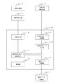
図1は、本実施形態に係る画像処理装置1の構成例を示すブロック図である。
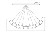
図1において、画像投影部2は、例えば画像投影面であるスクリーンなどである。画像投影装置3は、例えば図3に示すように、画像投影部2に対し、投影角度を変化させて画像を投影できるように複数のプロジェクタが配置された装置である。画像出力部4は、表示用の画像を画像投影装置3に出力するためのものである。
(First embodiment)
Hereinafter, a first embodiment of the present invention will be described with reference to the drawings.
FIG. 1 is a block diagram illustrating a configuration example of an
In FIG. 1, an
変角特性測定装置5は、ゴニオフォトメータ等、画像投影装置3から投影された画像の、画像投影部2上での変角特性を測定するための装置である。変角特性データ取得部6は、変角特性測定装置5にて測定した変角特性データを画像処理装置1に入力するためのものである。画像データ記憶部7は、画像投影装置3から投影して画像投影部2に表示するための画像データを記憶する記憶部である。画像データ取得部8は、画像データ記憶部7に記憶されている表示用の画像データを、画像処理装置1に読み出すためのものである。再現変角特性データ最適化部9は調整手段として機能し、画像データ取得部8により読み出された画像データの変角特性に対し、変角特性データ取得部6より入力された画像投影装置3の変角特性との組み合わせを最適化するためのものである。また、制御部10は、画像処理装置1全体を制御するためのものである。
The variable angle characteristic measuring
図2は、本実施形態において、変角特性を再現する処理手順の一例を示すフローチャートである。
まず、ステップS201において、制御部10により、変角特性測定装置5を用いて、画像投影装置3の各々のプロジェクタから、画像投影部2に投影した場合の変角特性を個々に測定する。そして、変角特性データ取得部6により、画像処理装置1にその変角特性データを入力する。
FIG. 2 is a flowchart illustrating an example of a processing procedure for reproducing the variable angle characteristic in the present embodiment.
First, in step S <b> 201, the
次に、ステップS202において、画像データ取得部8により、画像データ記憶部7に記憶されている表示用の画像データを画像処理装置1に読み出す。この時、画像データ記憶部7に記憶されている表示用の画像データは、各画素について、図4(b)に示すような、再現すべき変角特性データ(以下、ターゲット変角特性データと記す)も保持しているものとする。次に、ステップS203において、再現変角特性データ最適化部9は、再現画像の変角特性を最適化する画素の初期値(例えば、一番左上の画素)を、処理対象画素として設定する。
Next, in step S <b> 202, the image
次に、ステップS204において、再現変角特性データ最適化部9は、画像投影装置3の各プロジェクタの発光強度を調整することにより表示画素値を最適化する。具体的には、表示用の画像データにおける処理対象画素のターゲット変角特性データと、画像投影装置3にて投影される複数のプロジェクタの変角特性の和との誤差が最も小さくなるように、各プロジェクタの表示画素値を最適化する。このステップS204の処理の詳細については後述する。
Next, in step S204, the reproduction variable angle characteristic
次に、ステップS205において、再現変角特性データ最適化部9は、表示用の画像データにおける全ての画素について、各プロジェクタの表示画素値を最適化したかどうかを判断する。この判断の結果、まだ最適化していない画素が残っている場合は、ステップS206に進み、処理対象画素を未処理画素に変更する。そして、ステップS204に戻る。一方、ステップS205の判断の結果、全ての画素について最適化した場合は、ステップS207に進む。そしてステップS207において、ステップS204にて最適化した各プロジェクタの表示画素値に基づき、画像出力部4により表示用の画像を出力し、画像投影装置3にて、画像投影部2上に画像を投影する。
Next, in step S205, the reproduction variable angle characteristic
次に、ステップS204における複数のプロジェクタの表示画素値を最適化する処理の詳細について、図4を参照しながら説明する。
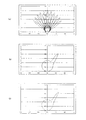
図4(a)は、スクリーンに対する角度を10度ずつ変えて設置した11台のプロジェクタの変角特性の一例を示す図であり、図4(b)は、表示用の画像データが保持するターゲット変角特性の一例を示す図である。ステップS204では、図4(b)に示すターゲット変角特性を、図4(a)に示すような複数のプロジェクタの変角特性の線形和によって再現するために、各プロジェクタの出力値を算出する。ステップS207において出力される表示画像の変角特性O(以下、合成変角特性と記す)は、複数のプロジェクタにおける変角特性Iの線形和として、以下の数1に示す式により表すことができる。
Next, details of the process of optimizing the display pixel values of the plurality of projectors in step S204 will be described with reference to FIG.
FIG. 4A is a diagram showing an example of the angle change characteristics of 11 projectors installed at different angles with respect to the screen by 10 degrees, and FIG. 4B shows the target held by the display image data. It is a figure which shows an example of a variable angle characteristic. In step S204, the output value of each projector is calculated in order to reproduce the target variable angle characteristic shown in FIG. 4B by the linear sum of the variable angle characteristics of a plurality of projectors as shown in FIG. . The change angle characteristic O of the display image output in step S207 (hereinafter referred to as a composite change angle characteristic) can be expressed by the

ここで、行列Oの要素{Oθ°}は、合成変角特性のθ°方向への反射強度を表し、行列aの要素{an}は、n番目のプロジェクタの出力強度を表す。また、行列Iの要素{In_θ°}は、n番目のプロジェクタの角度θ°方向への反射強度を表す。ステップS204では、ターゲット変換特性Tと、複数のプロジェクタにより合成された変角特性Oとの誤差が最小となるように、複数のプロジェクタの発光強度である出力値aを決定する。 Here, the element {Oθ °} of the matrix O represents the reflection intensity in the θ ° direction of the composite variable angle characteristic, and the element {a n } of the matrix a represents the output intensity of the nth projector. An element {I n _θ °} of the matrix I represents the reflection intensity in the angle θ ° direction of the nth projector. In step S204, the output value a which is the light emission intensity of the plurality of projectors is determined so that the error between the target conversion characteristic T and the variable angle characteristic O synthesized by the plurality of projectors is minimized.
図4(c)は、図4(b)の変角特性をターゲットとして算出した複数のプロジェクタにおける各出力値aにより計算した合成変角特性Oを示す図である。ここで、図4(c)に示す変角特性は、以下の数2に示す式を用いて計算される。 FIG. 4C is a diagram showing the composite variable angle characteristic O calculated by each output value a in a plurality of projectors calculated using the variable angle characteristic of FIG. 4B as a target. Here, the variable angle characteristic shown in FIG. 4C is calculated using the following equation (2).
式中、行列Tの要素{Tθ°}は、ターゲット変角特性のθ°方向への反射強度を表す。 In the equation, the element {Tθ °} of the matrix T represents the reflection intensity in the θ ° direction of the target deflection characteristic.
以上説明した処理制御を行うことにより、入力された画像データの変角特性を再現することができる。本実施形態では、複数のプロジェクタの並べ方の一例として、一方向の円周上に10度間隔で設置した11台のプロジェクタを用いた場合について説明した。しかしながら、プロジェクタの台数や、設置する幾何条件は、これに限定されるものではなく、ターゲットとなる変角特性データを所望の精度で再現することができれば、その台数や、幾何条件は特に限定されるものではない。 By performing the processing control described above, it is possible to reproduce the angle change characteristic of the input image data. In the present embodiment, as an example of how to arrange a plurality of projectors, a case has been described in which eleven projectors installed at intervals of 10 degrees on a circumference in one direction are used. However, the number of projectors and the geometric conditions to be installed are not limited to this, and the number and geometric conditions are not particularly limited as long as the target variable angle characteristic data can be reproduced with desired accuracy. It is not something.
また、本実施形態では、ターゲットとなる変角特性データが画像データとともに予め画像データ記憶部7に記憶されていることを前提として説明した。一方、例えば、被写体の形状データと、変角特性データとを入力した後に、一般的なCGレンダリング技術を用いて画像処理装置内にてレンダリング処理を行い、表示画像の変角特性データを算出するような構成であってもよい。さらには、複数のプロジェクタにより画像を投影する場合、投影面との角度の違いを補正するため、一般的なキーストーン補正を行うことにより、複数のプロジェクタ間の画素ズレを低減することもできる。
Further, in the present embodiment, the explanation has been made on the assumption that the target variable angle characteristic data is stored in advance in the image
(第2の実施形態)
第1の実施形態では、画像投影部2上での変角特性を、複数のプロジェクタそれぞれについて測定した。本実施形態においては、代表するプロジェクタの測定値を用いて、他のプロジェクタの変角特性を推定する例について説明する。
(Second Embodiment)
In the first embodiment, the variable angle characteristic on the
図5は、本実施形態に係る画像処理装置500の構成例を示すブロック図である。なお、画像投影部2から制御部10までの構成は、第1の実施形態において図1で説明した構成同一であるため、説明は省略する。
図5において、変角特性データ推定部501は、画像投影装置3から投影された画像の、画像投影部2上での変角特性を推定するためのものである。
FIG. 5 is a block diagram illustrating a configuration example of the
In FIG. 5, the angle variation characteristic data estimation unit 501 is for estimating the angle variation characteristic on the
図6は、本実施形態において、変角特性を再現する処理手順の一例を示すフローチャートである。なお、図6において、ステップS601及びS602以外のステップS202〜S207は、図2のステップS202〜S207と同一であるため、説明は省略する。
まず、ステップS601において、制御部10により、変角特性測定装置5を用いて、複数台のプロジェクタの中で代表する代表プロジェクタから画像投影部2に投影した場合の変角特性を測定する。そして、変角特性データ取得部6により、画像処理装置500にその変角特性データを入力する。
FIG. 6 is a flowchart illustrating an example of a processing procedure for reproducing the variable angle characteristic in the present embodiment. In FIG. 6, steps S202 to S207 other than steps S601 and S602 are the same as steps S202 to S207 of FIG.
First, in step S601, the
次に、ステップS602において、変角特性データ推定部501は、測定値である代表プロジェクタの変角特性データを用いて、他のプロジェクタの変角特性を推定する。ここで、本実施形態では、スクリーン(画像投影部2)に対し、90度の方向で設置したプロジェクタ(光軸がスクリーンの垂線方向と一致するプロジェクタ)を代表プロジェクタとする。そして、以下に、光軸をスクリーンの垂線から10度傾けたプロジェクタの変角特性を推定する例を示す。 Next, in step S602, the angle change characteristic data estimation unit 501 estimates the angle change characteristics of the other projectors using the angle change characteristic data of the representative projector that is the measurement value. Here, in the present embodiment, a projector (a projector whose optical axis coincides with the perpendicular direction of the screen) installed in a direction of 90 degrees with respect to the screen (image projection unit 2) is a representative projector. In the following, an example of estimating the deflection characteristics of a projector whose optical axis is tilted by 10 degrees from the normal of the screen is shown.
図7(a)は、測定した代表プロジェクタの変角特性データの一例を示す図である。まず、この変角特性に対し、例えば以下の数3に示す式にて表される、Phongモデル等を用いてフィッティングし、係数A、B、及びnを算出することにより、図7(b)に示すような拡散反射成分と、図7(c)に示すような正反射成分とに分離する。 FIG. 7A is a diagram illustrating an example of measured deflection angle characteristic data of the representative projector. First, by fitting the variable angle characteristics using, for example, the Phong model represented by the following equation (3) and calculating coefficients A, B, and n, FIG. And a regular reflection component as shown in FIG. 7C.
![]()
![]()
ここで、変角特性を推定するプロジェクタが配置されている幾何条件に基づき、数3に示す式中の、θ及びφの値を変更することにより、拡散反射成分、及び正反射成分を推定することができる。なお、図8(b)は、推定した拡散反射成分を示しており、図8(c)は、推定した正反射成分を示している。この結果、トータルの変角特性は、両者の和、すなわち、図8(a)に示す変角特性として推定することができる。
Here, the diffuse reflection component and the regular reflection component are estimated by changing the values of θ and φ in the equation shown in
以上のように本実施形態によれば、複数のプロジェクタの変角特性を全て測定する必要はなく、代表プロジェクタの測定値から推定することにより、変角特性の測定回数を低減することができる。なお、本実施形態では、代表プロジェクタとして、スクリーンに垂直なプロジェクタを選定した例を基に説明をしたが、他のプロジェクタを代表プロジェクタとしてもよい。また、変角特性データの推定モデルとして、Phongモデルを用いて説明したが、これも、所望の精度で推定可能なモデルであれば、特に限定されるものではない。 As described above, according to the present embodiment, it is not necessary to measure all the deflection characteristics of a plurality of projectors, and the number of measurement of the deflection characteristics can be reduced by estimating from the measurement values of the representative projector. In this embodiment, the description has been made based on an example in which a projector perpendicular to the screen is selected as the representative projector. However, another projector may be used as the representative projector. Further, although the Phong model has been described as the estimation model of the variable angle characteristic data, it is not particularly limited as long as it is a model that can be estimated with desired accuracy.
(その他の実施形態)
前述した第1及び第2の実施形態においては、説明を簡単にするため、輝度情報等、1次元の色情報の変角特性を再現する方法について説明した。一方、自然画像等のカラー画像を再現する場合には、R、G、Bの3つチャンネルごとに独立して変角特性を測定し、測定したそれぞれの変角特性データを取得して変角特性を最適化するようにしてもよい。また、分光データを波長ごとに独立に測定し、変角特性データとして取得することにより最適化するようにしてもよい。
(Other embodiments)
In the first and second embodiments described above, for the sake of simplicity, a method for reproducing the angle-change characteristics of one-dimensional color information such as luminance information has been described. On the other hand, when reproducing a color image such as a natural image, the angle-changing characteristics are measured independently for each of the three channels R, G, and B, and the measured angle-changing characteristic data is obtained to obtain the angle-changing angle. The characteristics may be optimized. Further, the spectroscopic data may be optimized for each wavelength, and optimized by obtaining the angle change characteristic data.
また、第1及び第2の実施形態において、ターゲット変角特性データは、表示用の画像データとともに画像データ記憶部7に予め記憶されているものとした。そこで、ターゲット変角特性データを保持していない場合などでは、例えば、一般的なCG(コンピュータグラフィックス)のレンダリング技術を用いて内部で計算するようにしてもよい。すなわち、被写体の3次元形状データ及び変角特性データから、被写体表面の法線と光源・視点との角度を算出し、レンダリングすることにより、再現する画像における各画素の変角特性を算出するようにしてもよい。
In the first and second embodiments, the target deflection characteristic data is stored in advance in the image
また、本発明は、以下の処理を実行することによっても実現される。即ち、上述した実施形態の機能を実現するソフトウェア(プログラム)を、ネットワーク又は各種記憶媒体を介してシステム或いは装置に供給し、そのシステム或いは装置のコンピュータ(またはCPUやMPU等)がプログラムを読み出して実行する処理である。 The present invention can also be realized by executing the following processing. That is, software (program) that realizes the functions of the above-described embodiments is supplied to a system or apparatus via a network or various storage media, and a computer (or CPU, MPU, or the like) of the system or apparatus reads the program. It is a process to be executed.
2 画像投影部、3 画像投影装置、4 画像出力部、6 変角特性データ取得部、8 画像データ取得部、9 再現変角特性データ最適化部、10 制御部 2 image projection unit, 3 image projection device, 4 image output unit, 6 variable angle characteristic data acquisition unit, 8 image data acquisition unit, 9 reproduction variable angle characteristic data optimization unit, 10 control unit
Claims (7)
複数の投影装置から投影するための画像データと、前記画像データの各画素における変角特性データとを取得する画像データ取得手段と、
前記画像データ取得手段により取得された変角特性データと前記特性データ取得手段により取得された変角特性データとの誤差が小さくなるように前記複数の投影装置の発光強度を調整する調整手段と、
前記調整手段によって調整された発光強度により、前記画像データを前記複数の投影装置に出力する出力手段とを有することを特徴とする画像処理装置。 Characteristic data acquisition means for acquiring variable angle characteristic data representing variable angle characteristics at a plurality of angles with respect to the image projection plane;
Image data acquisition means for acquiring image data to be projected from a plurality of projection devices, and angle variation characteristic data in each pixel of the image data;
Adjusting means for adjusting the light emission intensities of the plurality of projection devices so as to reduce an error between the variable angle characteristic data acquired by the image data acquisition unit and the variable angle characteristic data acquired by the characteristic data acquisition unit;
An image processing apparatus comprising: output means for outputting the image data to the plurality of projection apparatuses based on the light emission intensity adjusted by the adjustment means.
前記調整手段は、前記チャンネルごとに、前記複数の投影装置の発光強度を調整することを特徴とする請求項2に記載の画像処理装置。 The characteristic data acquisition means acquires the variable angle characteristic data for each of R, G, and B channels,
The image processing apparatus according to claim 2, wherein the adjustment unit adjusts light emission intensities of the plurality of projection apparatuses for each of the channels.
前記調整手段は、前記取得した分光データを用いて前記複数の投影装置の発光強度を調整することを特徴とする請求項1または2に記載の画像処理装置。 The characteristic data acquisition means acquires spectral data of the variable angle characteristic data for each wavelength,
The image processing apparatus according to claim 1, wherein the adjustment unit adjusts light emission intensities of the plurality of projection apparatuses using the acquired spectral data.
複数の投影装置から投影するための画像データと、前記画像データの各画素における変角特性データとを取得する画像データ取得工程と、
前記画像データ取得工程において取得された変角特性データと前記特性データ取得工程において取得された変角特性データとの誤差が小さくなるように前記複数の投影装置の発光強度を調整する調整工程と、
前記調整工程において調整された発光強度により、前記画像データを前記複数の投影装置に出力する出力工程とを有することを特徴とする画像処理方法。 A characteristic data acquisition step of acquiring variable angle characteristic data representing variable angle characteristics at a plurality of angles with respect to the image projection plane;
An image data acquisition step for acquiring image data for projection from a plurality of projection devices, and angle variation characteristic data in each pixel of the image data;
An adjustment step of adjusting the light emission intensities of the plurality of projection devices such that an error between the variable angle characteristic data acquired in the image data acquisition step and the variable angle characteristic data acquired in the characteristic data acquisition step is reduced ;
An image processing method comprising: an output step of outputting the image data to the plurality of projection devices based on the light emission intensity adjusted in the adjustment step.
Priority Applications (1)
| Application Number | Priority Date | Filing Date | Title |
|---|---|---|---|
| JP2010117692A JP5541698B2 (en) | 2010-05-21 | 2010-05-21 | Image processing apparatus, image processing method, and program |
Applications Claiming Priority (1)
| Application Number | Priority Date | Filing Date | Title |
|---|---|---|---|
| JP2010117692A JP5541698B2 (en) | 2010-05-21 | 2010-05-21 | Image processing apparatus, image processing method, and program |
Publications (2)
| Publication Number | Publication Date |
|---|---|
| JP2011249875A JP2011249875A (en) | 2011-12-08 |
| JP5541698B2 true JP5541698B2 (en) | 2014-07-09 |
Family
ID=45414647
Family Applications (1)
| Application Number | Title | Priority Date | Filing Date |
|---|---|---|---|
| JP2010117692A Expired - Fee Related JP5541698B2 (en) | 2010-05-21 | 2010-05-21 | Image processing apparatus, image processing method, and program |
Country Status (1)
| Country | Link |
|---|---|
| JP (1) | JP5541698B2 (en) |
Family Cites Families (5)
| Publication number | Priority date | Publication date | Assignee | Title |
|---|---|---|---|---|
| JP4244391B2 (en) * | 1997-04-04 | 2009-03-25 | ソニー株式会社 | Image conversion apparatus and image conversion method |
| JP4826700B2 (en) * | 2004-02-18 | 2011-11-30 | 富士ゼロックス株式会社 | 3D display device |
| JP5489514B2 (en) * | 2009-04-09 | 2014-05-14 | キヤノン株式会社 | Color processing method, color processing apparatus, and program |
| JP5235805B2 (en) * | 2009-07-13 | 2013-07-10 | キヤノン株式会社 | Color processing method, color processing apparatus, and program |
| JP5562005B2 (en) * | 2009-11-02 | 2014-07-30 | キヤノン株式会社 | Image processing apparatus and image processing method |
-
2010
- 2010-05-21 JP JP2010117692A patent/JP5541698B2/en not_active Expired - Fee Related
Also Published As
| Publication number | Publication date |
|---|---|
| JP2011249875A (en) | 2011-12-08 |
Similar Documents
| Publication | Publication Date | Title |
|---|---|---|
| JP4630547B2 (en) | Method and system for outputting formatted information related to geometric distortion | |
| JP4295613B2 (en) | Method and system for outputting information relating to equipment defects | |
| US10547822B2 (en) | Image processing apparatus and method to generate high-definition viewpoint interpolation image | |
| JP4440066B2 (en) | Stereo image generation program, stereo image generation system, and stereo image generation method | |
| US9008412B2 (en) | Image processing device, image processing method and recording medium for combining image data using depth and color information | |
| US20160227184A1 (en) | Digital multi-dimensional image photon platform system and methods of use | |
| WO2017006780A1 (en) | Information processing device and method, and program | |
| WO2008102366A2 (en) | A method and a system for calibrating and/or visualizing a multi image display and for reducing ghosting artifacts | |
| EP2715669A1 (en) | Systems and methods for alignment, calibration and rendering for an angular slice true-3d display | |
| JP2004109246A (en) | Projection system | |
| JP2019082680A (en) | Method, device, and method for calibration of three-dimensional display device | |
| JP5809607B2 (en) | Image processing apparatus, image processing method, and image processing program | |
| JP6869652B2 (en) | Image processing device, imaging device, image processing method, image processing program, and storage medium | |
| JP5762015B2 (en) | Image processing apparatus, image processing method, and program | |
| JP5576745B2 (en) | Image processing apparatus and method | |
| JP5541698B2 (en) | Image processing apparatus, image processing method, and program | |
| TWI514882B (en) | Method of generating view-dependent compensated images | |
| JP5474113B2 (en) | Image processing apparatus and image processing method | |
| JP4615430B2 (en) | Image generation apparatus, image generation method, and image generation program | |
| JP2006211383A (en) | Stereoscopic image processing apparatus, stereoscopic image display apparatus, and stereoscopic image generating method | |
| JP6768431B2 (en) | Image generator and program | |
| CN108377383B (en) | Multi-projection 3D system light field contrast adjusting method and system | |
| JP6100086B2 (en) | Image processing apparatus and image processing method | |
| WO2022044806A1 (en) | Information processing device and method | |
| JP6103767B2 (en) | Image processing apparatus, method, and program |
Legal Events
| Date | Code | Title | Description |
|---|---|---|---|
| A621 | Written request for application examination |
Free format text: JAPANESE INTERMEDIATE CODE: A621 Effective date: 20130521 |
|
| A977 | Report on retrieval |
Free format text: JAPANESE INTERMEDIATE CODE: A971007 Effective date: 20131217 |
|
| A131 | Notification of reasons for refusal |
Free format text: JAPANESE INTERMEDIATE CODE: A131 Effective date: 20140121 |
|
| A521 | Request for written amendment filed |
Free format text: JAPANESE INTERMEDIATE CODE: A523 Effective date: 20140324 |
|
| TRDD | Decision of grant or rejection written | ||
| A01 | Written decision to grant a patent or to grant a registration (utility model) |
Free format text: JAPANESE INTERMEDIATE CODE: A01 Effective date: 20140408 |
|
| A61 | First payment of annual fees (during grant procedure) |
Free format text: JAPANESE INTERMEDIATE CODE: A61 Effective date: 20140430 |
|
| R151 | Written notification of patent or utility model registration |
Ref document number: 5541698 Country of ref document: JP Free format text: JAPANESE INTERMEDIATE CODE: R151 |
|
| LAPS | Cancellation because of no payment of annual fees |