JP5538410B2 - Whirling prevention drill bit, well site system and method of use thereof - Google Patents
Whirling prevention drill bit, well site system and method of use thereof Download PDFInfo
- Publication number
- JP5538410B2 JP5538410B2 JP2011533808A JP2011533808A JP5538410B2 JP 5538410 B2 JP5538410 B2 JP 5538410B2 JP 2011533808 A JP2011533808 A JP 2011533808A JP 2011533808 A JP2011533808 A JP 2011533808A JP 5538410 B2 JP5538410 B2 JP 5538410B2
- Authority
- JP
- Japan
- Prior art keywords
- drill bit
- orifices
- fluid
- drill
- pads
- Prior art date
- Legal status (The legal status is an assumption and is not a legal conclusion. Google has not performed a legal analysis and makes no representation as to the accuracy of the status listed.)
- Expired - Fee Related
Links
Images


Classifications
-
- E—FIXED CONSTRUCTIONS
- E21—EARTH DRILLING; MINING
- E21B—EARTH DRILLING, e.g. DEEP DRILLING; OBTAINING OIL, GAS, WATER, SOLUBLE OR MELTABLE MATERIALS OR A SLURRY OF MINERALS FROM WELLS
- E21B7/00—Special methods or apparatus for drilling
- E21B7/04—Directional drilling
- E21B7/06—Deflecting the direction of boreholes
- E21B7/065—Deflecting the direction of boreholes using oriented fluid jets
-
- E—FIXED CONSTRUCTIONS
- E21—EARTH DRILLING; MINING
- E21B—EARTH DRILLING, e.g. DEEP DRILLING; OBTAINING OIL, GAS, WATER, SOLUBLE OR MELTABLE MATERIALS OR A SLURRY OF MINERALS FROM WELLS
- E21B10/00—Drill bits
- E21B10/60—Drill bits characterised by conduits or nozzles for drilling fluids
- E21B10/602—Drill bits characterised by conduits or nozzles for drilling fluids the bit being a rotary drag type bit with blades
-
- E—FIXED CONSTRUCTIONS
- E21—EARTH DRILLING; MINING
- E21B—EARTH DRILLING, e.g. DEEP DRILLING; OBTAINING OIL, GAS, WATER, SOLUBLE OR MELTABLE MATERIALS OR A SLURRY OF MINERALS FROM WELLS
- E21B17/00—Drilling rods or pipes; Flexible drill strings; Kellies; Drill collars; Sucker rods; Cables; Casings; Tubings
- E21B17/10—Wear protectors; Centralising devices, e.g. stabilisers
- E21B17/1092—Gauge section of drill bits
Description
本発明は、坑井内における掘削しながらドリルビット及び/又は坑底組立体のふれまわり及び他の逸れ又は逸脱を阻止するシステム及び方法に関する。 The present invention relates to a system and method for preventing whirling and other deflections or deviations of a drill bit and / or bottom assembly while drilling in a well.
ドリルビットふれまわり及び逸れは、掘削業界における重要な問題である。油、ガス、水及び他の天然資源は、地下4,000〜10,000フィート(1,219〜3,048m)のところに位置している場合が多い。その結果、坑井の逸れが1°であっても、結果として、掘削距離、掘削時間及び掘削費が著しく増大する場合がある。 Drill bit whirling and deflection are important issues in the drilling industry. Oil, gas, water and other natural resources are often located 4,000 to 10,000 feet underground (1,219 to 3,048 meters). As a result, even if the well deviation is 1 °, the excavation distance, excavation time and excavation cost may increase significantly as a result.
或る用途では、掘削業者は、垂直坑井を探し求めている。滑らかな垂直坑井は、最小の隙間で大径ケーシングの降下を容易にすると共に坑井建造作業において或る後の状態でケーシングの余分のストリングを用いる可能性を与える。ドリフトしてバーティカリティから遠ざかったりこれに戻ったりする坑井は、このオプションを台無しにする場合がある。加うるに、多数の坑井が単一プラットホームから掘削される場合、それにより、ドリルストリングの衝突が生じる場合がある。 In some applications, drillers are seeking vertical wells. Smooth vertical wells facilitate the lowering of large diameter casings with minimal clearance and the possibility of using extra strings of casings at some later stage in well construction operations. Wells that drift away from and return to verticality may ruin this option. In addition, if a large number of wells are drilled from a single platform, this can cause drill string collisions.
たとえ制御された制御型操向性又は傾斜掘削用途であっても、例えば砕けた岩石の下、急な下り坂になっている地層中又は構造地質学的に活動性の領域中の標的までの掘削の際に所望の坑跡を維持することが非常に望ましい場合がある。 Even for controlled controlled steerability or sloped drilling applications, for example, under broken rocks, in steep downhill formations or in targets in structural geologically active areas It may be highly desirable to maintain the desired pits during excavation.
加うるに、ドリルビットのふれまわり、即ち、ビットの回転中心がその幾何学的中心からずれて離れる状態により、深刻な問題が生じる。かかる問題としては、非円筒形の穴、坑井の逸れ及び過剰のビット摩耗の発生が挙げられる。 In addition, serious problems arise due to the whirling of the drill bit, i.e. the state in which the center of rotation of the bit is offset away from its geometric center. Such problems include non-cylindrical holes, well deflection and excessive bit wear.
従来型ふれまわり防止ドリルビットは、カッタと岩石の相互作用によるバランスを欠いたアンバランスな又は不均衡状態の横力を作ることによりふれまわりを減少させようとしている。この不均衡状態の力は、切断作用が滑らかであって連続しており且つカッタが摩耗しておらず又は損傷していない場合にのみ予測可能な大きさ及び方向を有する。切断作用が連続プロセスではなく不連続(断続)プロセスである場合が多いので(例えば、カッタが連続掘屑(カッティングス)ではなくチップを発生させる場合)、これら条件がどれもきまって生じるわけではない。岩石がチッピング作用によって除去される場合、大きさ及び方向は、一定でもなければ予測可能でもない。 Conventional anti-spin drill bits attempt to reduce run-out by creating an unbalanced or unbalanced lateral force that lacks balance due to the interaction between the cutter and the rock. This unbalanced force has a magnitude and direction that is predictable only when the cutting action is smooth and continuous, and the cutter is not worn or damaged. Because the cutting action is often a discontinuous (intermittent) process rather than a continuous process (for example, when the cutter generates chips instead of continuous cuttings), not all of these conditions occur . When rock is removed by chipping, the size and direction are neither constant nor predictable.
したがって、ふれまわり及び逸れを阻止する装置及び方法が要望され続けている。 Accordingly, there continues to be a need for devices and methods for preventing whirling and deflection.
本発明は、一観点において、ドリルビットであって、ドリルストリングと流体連通状態にある内部キャビティと、ドリルビットの外部に設けられた第1の計器パッドとを有し、第1の計器パッドは、内部キャビティと流体連通状態にある第1のオリフィスを有し、ドリルビットは、流体が第1のオリフィスから連続して流出するよう構成されていることを特徴とするドリルビットを提供する。 In one aspect, the present invention includes a drill bit, an internal cavity in fluid communication with the drill string, and a first instrument pad provided outside the drill bit, wherein the first instrument pad is And a first orifice in fluid communication with the internal cavity, wherein the drill bit is configured to allow fluid to flow continuously out of the first orifice.
本発明は、別の観点において、坑井現場システムであって、ドリルストリングと、ドリルストリングに結合されたケリーと、ドリルビットとを有し、ドリルビットは、ドリルストリングと流体連通状態にある内部キャビティと、ドリルビットの外部に設けられた第1の計器パッドとを有し、第1の計器パッドは、内部キャビティと流体連通状態にある第1のオリフィスを有し、ドリルビットは、流体が第1のオリフィスから連続して流出するよう構成されていることを特徴とする坑井現場システムを提供する。 In another aspect, the present invention is a well site system comprising a drill string, a kelly coupled to the drill string, and a drill bit, the drill bit being in fluid communication with the drill string. A cavity and a first instrument pad disposed external to the drill bit, the first instrument pad having a first orifice in fluid communication with the interior cavity, A well site system is provided that is configured to continuously flow out of a first orifice.
本発明は、更に別の観点において、地下地層に湾曲したボーリング孔を穿孔する方法であって、ドリルビットをドリルストリングに取り付けるステップを有し、ドリルビットは、ドリルストリングと流体連通状態にある内部キャビティと、ドリルビットの外部に設けられた第1の計器パッドとを有し、第1の計器パッドは、内部キャビティと流体連通状態にある第1のオリフィスを有し、ドリルビットは、流体が第1のオリフィスから連続して流出するよう構成され、この方法は、ドリルストリングの回転とドリルストリングを通るドリルビットへの流体の圧送を実質的に同時に実施するステップを更に有することを特徴とする方法を提供する。 In yet another aspect, the present invention provides a method for drilling a curved borehole in an underground formation, comprising the step of attaching a drill bit to the drill string, the drill bit being in fluid communication with the drill string. A cavity and a first instrument pad disposed external to the drill bit, the first instrument pad having a first orifice in fluid communication with the interior cavity, The method further comprises the steps of substantially simultaneously performing rotation of the drill string and pumping of fluid through the drill string and into the drill bit, wherein the method is configured to continuously flow out of the first orifice. Provide a method.
本発明の性状及び所望の目的のより完全な理解を得るために、添付の図面と関連して行なわれる以下の詳細な説明を参照されたい。なお、幾つかの図を通じて同一の参照符号は、対応の部分を示している。 For a more complete understanding of the nature and desired objects of the present invention, reference should be made to the following detailed description taken in conjunction with the accompanying drawings. Note that the same reference numerals denote corresponding parts throughout the drawings.
本発明は、坑井内における掘削しながらドリルビット及び/又は坑底組立体のふれまわり及び他の逸れを阻止するシステム及び方法を提供する。 The present invention provides a system and method for preventing whirling and other deflections of a drill bit and / or bottom assembly while drilling in a well.
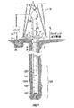
本明細書において開示される本発明は、或る範囲の掘削作業、例えば油、ガス及び水の掘削に用いられるようになっている。したがって、ビット本体は、油、ガス及び水業界において通常用いられている坑井現場システムに組み込まれるよう設計されている。例示の坑井現場システムが図1に示されている。 The invention disclosed herein is intended for use in a range of drilling operations, such as oil, gas and water drilling. Thus, the bit body is designed to be incorporated into well field systems commonly used in the oil, gas and water industries. An exemplary well site system is shown in FIG.
図1は、本発明を利用することができる坑井現場システムを示している。坑井現場は、オンショワーであっても良くオフショワーであっても良い。この例示のシステムでは、ボーリング孔11が周知の仕方の回転掘削によって地下地層中に形成されている。本発明の実施形態は、以下に説明するように傾斜掘削も又利用できる。
FIG. 1 illustrates a well site system that can utilize the present invention. The well site may be on-shower or off-shower. In this exemplary system, a
ドリルストリング12は、ボーリング孔11内に吊り下げられており、このドリルストリングは、坑底組立体100を有し、この坑底組立体は、その下端部にドリルビット105を有する。坑外システムは、ボアホール11を覆って位置決めされたプラットホーム・デリック組立体10を有し、この組立体10は、回転テーブル16、ケリー17、フック18及び回転スイベル19を含む。ドリルストリング12は、回転テーブル16により回転し、図示していない手段により付勢され、かかる手段は、ドリルストリングの上端部のところに位置するケリー17に係合する。ドリルストリング12は、ケリー17及び回転スイベル19を介してトラベリングブロック(これ又図示せず)に取り付けられたフック18から吊り下げられており、回転スイベル19は、フックに対するドリルストリングの回転を可能にする。周知のように、変形例として、頂部駆動システムを用いても良い。
The
この実施形態の実施例では、坑外システムは、坑井現場のところに構成されたピット27内に貯留されている掘削流体又は泥水26を更に有する。ポンプ29が掘削流体26をスイベル19に設けられているポートを経てドリルストリング12の内部に送り出し、それにより、掘削流体は、方向を示す矢印8で示されているようにドリルストリング12を通って下方に流れる。掘削流体は、ドリルビット105に設けられたポートを経てドリルストリング12から流出し、次に、方向を示す矢印9によって示されているようにドリルストリングの外部とボーリング孔の壁との間の環状領域を通って上方に循環する。この周知で仕方では、掘削流体は、ドリルビット105を潤滑し、これが再循環のためにピット27に戻されているときに地層掘屑を地表まで運ぶ。
In the example of this embodiment, the out-of-well system further includes a drilling fluid or
図示の実施形態の坑底組立体100は、掘削しながらロッギング(物理検層)する(LWD)モジュール120、掘削しながら測定する(MWD)モジュール130、モータ付き回転操向性システム及びドリルビット105を含む。
The
LWDモジュール120は、当該技術分野で知られているように特定形式のドリルカラー内に収容され、このLWDモジュールは、1つ又は複数個の公知形式のロッギングツールを有するのが良い。また、例えば120Aのところに示されているように2つ以上のLWD及び/又はMWDモジュールを使用しても良いことは理解されよう。(変形例として、120の位置のところのモジュールと全体として言った場合、このことは、120Aの位置のところのモジュールも意味する場合がある)。LWDモジュールは、情報を測定し、処理し又は記憶すると共に坑外機器と通信する機能を含む。この実施形態では、LWDモジュールは、圧力測定装置を含む。
The
MWDモジュール130も又、当該技術分野において知られているように特定形式のドリルカラー内に収容され、このMWDモジュールは、ドリルストリング及びドリルビットの特性を計測する1つ又は2つ以上の装置を有するのが良い。MWDツールは、ダウンホールシステムに対する電力を発生させる装置(図示せず)を更に含む。これは、代表的には、掘削流体の流れによって動力供給される泥水タービン発電機であるのが良いが、理解されるべきこととして、他の電力及び/又はバッテリシステムを用いても良い。この実施形態では、MWDモジュールは、以下の形式の測定装置、即ち、ビットに加わる重量測定装置、トルク測定装置、振動測定装置、衝撃測定装置、スティックスリップ測定装置、方向測定装置及び勾配測定装置のうちの1つ又は2つ以上を含む。
The
坑井現場システムの特定の有利な使用は、制御型操向性又は「傾斜掘削」と関連している。この実施形態では、回転操向性サブシステム150(図1)が提供されている。傾斜掘削は、坑井が元々取る経路からの坑井の意図した逸脱である。換言すると、傾斜掘りは、ドリルストリングが所望の方向を移動するようにするドリルストリングの操行である。 A particular advantageous use of well site systems is associated with controlled steering or “tilt drilling”. In this embodiment, a rotational steering subsystem 150 (FIG. 1) is provided. Sloped excavation is the intended departure of a well from the path originally taken by the well. In other words, tilt digging is the manipulation of a drill string that causes the drill string to move in a desired direction.
傾斜掘削は、例えば、オフショワー掘削において有利である。というのは、かかる傾斜掘削により、多くの坑井を単一プラットホームから掘削できるからである。傾斜掘削は又、貯留層を通る水平掘削を可能にする。水平掘削により長さの長い坑井が貯留層を横行することができ、それにより坑井からの産出量が増大する。 Inclined excavation is advantageous, for example, in offshore excavation. This is because such well drilling allows many wells to be drilled from a single platform. Sloped drilling also allows horizontal drilling through the reservoir. Horizontal drilling allows long wells to traverse the reservoir, thereby increasing output from the wells.
傾斜掘削システムは、垂直掘削作業にも利用できる。ドリルビットは、穿孔中の地層の予期しない性状又はドリルビットの受ける力の変化に起因して計画された掘削坑跡から方向を変える場合が多い。かかる逸脱が生じると、傾斜掘削システムを用いてドリルビットを正しいコースに戻すことができる。 The inclined excavation system can also be used for vertical excavation work. Drill bits often change direction from a planned excavation site due to unexpected properties of the formation being drilled or changes in the force experienced by the drill bit. When such a deviation occurs, the drill bit can be returned to the correct course using an inclined drilling system.
公知の傾斜掘削方法は、回転操向性システム(“RSS”)の使用を含む。RSSでは、ドリルストリングリングを地表から回転させ、ダウンホール装置によりドリルビットが所望の方向に掘削を行なうようにする。ドリルストリングを回転させることにより、ドリルストリングは掘削中にハングアップ状態になり又は固着状態になる恐れが大幅に減少する。地中に逸れ状態のボーリング孔を穿孔する回転操向性掘削システムは、一般に、「ポイント・ザ・ビット(point-the-bit)」システムか「プッシュ・ザ・ビット(push-the-bit)」システムかのいずれかとして分類される場合がある。 Known inclined excavation methods include the use of a rotational steering system (“RSS”). In RSS, a drill string ring is rotated from the ground surface, and a drill bit drills in a desired direction by a downhole device. By rotating the drill string, the risk of the drill string becoming hung up or stuck during drilling is greatly reduced. Rotary steerable drilling systems that drill boring holes in the ground are generally “point-the-bit” systems or “push-the-bit” systems. May be classified as any of the systems.
ポイント・ザ・ビットシステムでは、ドリルビットの回転軸線を新たな孔の全体方向に坑底組立体の局所軸線から逸らす。孔を上側及び下側スタビライザ接触点及びドリルビットにより定められる慣例の3点幾何学的形状に従って伸長させる。ドリルビット軸線の逸脱角度とドリルビットの下側スタビライザとの間の有限距離の組み合わせの結果として、曲線を生成させるのに必要な非共線条件が得られる。これを達成できる多くのやり方が存在し、かかるやり方としては、下側スタビライザの近くに位置する坑底組立体中の1点のところの固定曲げ又は上側スタビライザと下側スタビライザとの間に分布されたドリルビット駆動シャフトの曲げの利用が挙げられる。ドリルビットは、その理想化された形態では、側方に切断することが必要とされない。というのは、ビット軸線を湾曲した孔の方向に連続して回転させるからである。ポイント・ザ・ビット型回転操向性システムの例及びこれらの動作原理は、米国特許出願公開第2002/0011359号明細書、同第2001/0052428号明細書並びに米国特許第6,394,193号明細書、同第6,364,034号明細書、同第6,244,361号明細書、同第6,158,529号明細書、同第6,092,610号明細書及び同第5,113,953号明細書に記載されており、これら特許文献を全て参照により引用し、これらの記載内容全体を本明細書の一部とする。 In the point-the-bit system, the axis of rotation of the drill bit is diverted from the local axis of the bottom hole assembly in the direction of the new hole. The holes are elongated according to the conventional three-point geometry defined by the upper and lower stabilizer contact points and the drill bit. As a result of the combination of the finite distance between the drill bit axis deviation angle and the lower stabilizer of the drill bit, the non-collinear conditions necessary to generate the curve are obtained. There are many ways in which this can be achieved, such as a fixed bend at one point in the bottom hole assembly located near the lower stabilizer or distributed between the upper and lower stabilizers. The use of a drill bit drive shaft bend can be mentioned. The drill bit is not required to cut laterally in its idealized form. This is because the bit axis is continuously rotated in the direction of the curved hole. Examples of point-the-bit rotational steering systems and their operating principles are disclosed in US 2002/0011359, 2001/0052428 and US 6,394,193. No. 6,364,034, No. 6,244,361, No. 6,158,529, No. 6,092,610 and No. 5 No. 113,953, all of which are incorporated herein by reference, the entire contents of which are hereby incorporated by reference.
プッシュ・ザ・ビット型回転操向性システムでは、通常、ビット軸線を坑底組立体の局所軸線から逸らす上で特に該当する機構体は存在せず、その代わり、上側スタビライザ又は下側スタビライザのうちのいずれか一方又は両方が孔の進行方向に関して優先的に差し向けられる方向に偏心力又は変位を加えるようにすることにより必要条件としての非共線条件が達成される。この場合も又、これを達成できる多くのやり方が存在し、かかるやり方としては、非回転(孔に対して)偏心スタビライザ(変位を利用した方式)及び力を所望の操向方向にドリルビットに加える偏心アクチュエータの利用が挙げられる。この場合も又、操向は、ドリルビットと少なくとも2つの他の接触点との間に非共振関係を作ることによって達成される。ドリルビットは、その理想化された形態では、湾曲した孔を形成するために側方に切断を行なう必要がある。プッシュ・ザ・ビット型回転操向性システムの例及びこれらの動作原理は、米国特許第5,265,682号明細書、同第5,553,678号明細書、同第5,803,185号明細書、同第6,089,332号明細書、同第5,695,015号明細書、同第5,685,379号明細書、同第5,706,905号明細書、同第5,553,679号明細書、同第5,673,763号明細書、同第5,520,255号明細書、同第5,603,385号明細書、同第5,582,259号明細書、同第5,778,992号明細書及び同第5,971,085号明細書に記載されており、これら特許文献を全て参照し引用し、これらの記載内容全体を本明細書の一部とする。 In push-the-bit rotational steering systems, there is usually no special mechanism for deflecting the bit axis from the local axis of the bottom hole assembly, instead of the upper or lower stabilizer. The necessary non-collinear condition is achieved by applying an eccentric force or displacement in a direction in which either one or both are preferentially directed with respect to the direction of travel of the hole. Again, there are many ways in which this can be achieved, including non-rotating (relative to the hole) eccentric stabilizer (displacement based) and force the drill bit in the desired steering direction. Use of an eccentric actuator to be added can be mentioned. Again, steering is achieved by creating a non-resonant relationship between the drill bit and at least two other contact points. The drill bit, in its idealized form, needs to be cut laterally to form a curved hole. Examples of push-the-bit rotational steering systems and their operating principles are described in US Pat. Nos. 5,265,682, 5,553,678, and 5,803,185. No. 6,089,332, No. 5,695,015, No. 5,685,379, No. 5,706,905, No. No. 5,553,679, No. 5,673,763, No. 5,520,255, No. 5,603,385, No. 5,582,259 No. 5,778,992 and US Pat. No. 5,971,085, all of which are referenced and cited, and their entire contents are incorporated herein by reference. Part.
本明細書において説明する本発明の特定の実施形態は、ふれまわり及び/又は逸脱を減少させるドリルビット105及び坑底組立体100を提供している。
Certain embodiments of the invention described herein provide a
ふれまわり防止ビットWhirling prevention bit
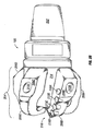
図2は、ドリルビット105を示している。ドリルビット105は、後続端部202及び切断部分204を有している。後続端部202は、ドリルストリング12との直接的又は間接的接続が可能であるようになっている。切断部分204は、1つ又は2つ以上のリブ206A,206B,206C,206Dを有する。リブ206は、計器区分208を有し、これら計器区分は、カッタ210により穿孔されたボーリング孔の壁に接触する。カッタ210がリブ206B上にのみ示されているが、カッタ210は、特定の掘削状況にとって有利であるように複数のリブ206又はリブ206の全てに形成されるのが良い。
FIG. 2 shows the
本発明の実施形態では、1つ又は2つ以上のオリフィス212がドリルビット105の外部に設けられている。オリフィス212は、計器区分208に又はリブ206相互間の谷部214に設けられるのが良い。オリフィス212により、ドリルストリング12の内部からの流体26がドリルビットから流出して安定性の実現を達成すると共にふれまわりを減少させることができる。追加のオリフィスがドリルビット105、例えば、当該技術分野において知られているように潤滑及び掘屑の除去のために先導端部216に設けられるのが良い。
In an embodiment of the present invention, one or more orifices 212 are provided outside the
幾つかの実施形態によっては、ドリルビット105は、単一のオリフィス212を有する。掘削流体26は、オリフィス212から流出し、そしてボーリング孔11の壁に接触し、それにより、オリフィス212及び計器区分208の向きに実質的に垂直な横力を生じさせる。この力により、ふれまわり防止効果が得られる。
In some embodiments, the
実施形態によっては、オリフィス212は、カッタ210のうちの大部分から見て実質的に反対側に位置決めされる。例えば、カッタ210がドリルビット105に沿って長手方向に配置される場合、オリフィス212は、カッタ210から見て約180°のところに配置されるのが良い。かかる実施形態では、オリフィス212から放出された掘削流体は、ドリルビットをカッタ210の方向に押す横力を生じさせる。この実施形態は、(1)カッタ210とボーリング孔11の壁との間の接触を増大させると共に/或いは(2)カッタ210とボーリング孔壁との接触に起因して生じる横力を帳消しにする。
In some embodiments, the orifice 212 is positioned substantially opposite as viewed from the majority of the
他の実施形態では、オリフィス212は、カッタ210の大部分の後ろに約90°のところに位置決めされる。この原理の例証として、図2Aに示されている状況を考察する。ドリルビット105は、ボーリング孔11内で反時計回りの方向に回転している。カッタ210は、正にボーリング孔壁220からの突起218に当たろうとしている。突起218が特に強固な材料である場合、突起は、最初にカッタ210との接触時には少なくとも瞬間的には無傷状態のままであろう。ドリルビット105に加わる回転力により、ドリルビット105は、計器パッド206Aがボーリング孔壁220に接触するまで負のy方向に動く。しかしながら、オリフィス212が計器パッド206Aに設けられている場合、掘削流体26は、正のy方向の力を生じさせ、それにより、ドリルビット105がオフセンタ状態に動く傾向を打ち消す。さらに、正のy方向の力は、ビット105全体を動かしそれにより追加の力をカッタ210に及ぼしてボーリング孔の伸長を助ける。
In other embodiments, the orifice 212 is positioned approximately 90 ° behind the majority of the
他のカッタ210及びオリフィス212についての他の形態は、本発明の範囲に含まれる。例えば、ドリルビット105の回転及び複数個のカッタ210との接触により生じる力の合成ベクトルは、既知の方程式及び技術を用いて計算できる。オリフィス212は、最も生じそうな力のベクトルを相殺するよう構成されているのが良い。
Other configurations for
オリフィス212からの掘削流体26の水力を利用することによって、ドリルビット105は、ビットのふれまわりを減少させると共に/或いは阻止する予測可能で且つ一定の不均衡状態の力を生じさせる。不均衡状態の力の方向は、ポートの位置が与えられている場合には既知である。不均衡状態の力の大きさは、オリフィス212とボーリング孔壁220との間の距離、ボーリング孔内の掘削流体26とドリルストリング12内の掘削流体26の差圧及びオリフィス212の幾何学的形状(例えば、寸法形状)の関数である。さらに、カッタ210に対する摩耗及び損傷は、横力の大きさ及び方向に影響を及ぼさないはずである。
By utilizing the hydraulic power of the
実施形態によっては、オリフィス212の外部は、掘削流体26がオリフィス212から出る際に大きな水圧を生じさせるために隆起環状体又は他の幾何学的特徴部によって包囲される。かかる特徴部及び/又は計器区分206全体は、耐摩耗性又は表面硬化材料、例えば多結晶ダイヤモンド(PCD)で被覆されるのが良く又は全体がこれから作られるのが良い。
In some embodiments, the exterior of the orifice 212 is surrounded by a raised annulus or other geometric feature to create a large water pressure as the
自己安定化ビット及び坑底組立体Self-stabilizing bit and bottom hole assembly
本発明の別の実施形態は、1つ又は2つ以上のオリフィス212を利用してボーリング孔内でドリルビット105及び/又は坑底組立体(BHA)を安定化する。
Another embodiment of the present invention utilizes one or more orifices 212 to stabilize the
図3Aは、ドリルビット105の断面図であり、3つの計器パッド206A,206B,260Cが全体としてドリルビット105の周囲に沿って互いに間隔(例えば、中心で120°)を置いて配置されており、各計器パッドは、それぞれ、212A,212B,212Cを有している。掘削状態26(太線で表されている)がドリルビット105の内部からオリフィス212A,212B,212Cを通って流出する。
FIG. 3A is a cross-sectional view of the
図3Aに示されているドリルビット105は、全体として、ボーリング孔11内に心出しされている。したがって、掘削流体により生じる水力は、互いに打ち消し合う。しかしながら、ドリルビット15が図3Bに示されているようにオフセンタ状態に動いた場合、オリフィス212Aからの掘削状態26によって生じる力のベクトルの大きさは、オリフィス212Aとボーリング孔壁220との間の離隔距離が減少するにつれて増大することになる。それと同時に、オリフィス212B,212Cにより生じる力のベクトルが減少し、その結果、ドリルビット壁220から押し離す正味の力のベクトル(矢印222によって表されている)が生じる。
The
実施形態によっては、1つ又は2つ以上のオリフィスへの流体の流量は、1つ又は2つ以上の弁(例えば、チョーク弁)によって制限される。管類又は他の手段によって単一の弁を各オリフィスに連結しても良い。より好ましくは、各オリフィスは、別々の弁によって別個独立に調節される。別個独立の調整により、掘削流体26が特定のオリフィス212に流れる量は、他のオリフィス212又は他のポート(例えば、ドリルビット105の前縁又は先導縁部216に設けられているポート)から奪うよう所望のしきい値を超えて増大することがない。
In some embodiments, the flow rate of fluid to one or more orifices is limited by one or more valves (eg, choke valves). A single valve may be connected to each orifice by tubing or other means. More preferably, each orifice is independently adjusted by a separate valve. With separate and independent adjustments, the amount of
図3A及び図3Bの実施形態は、3つのオリフィス212を備えたドリルビット105を示しているが、本明細書において説明する本発明の範囲は、ドリルビット105又は坑底組立体の安定化のための任意の数のオリフィス212による流体の使用を含む。例えば、単一のオリフィスを備えたドリルビット105は、3つのオリフィスを備えたドリルビット105とほぼ同じ作用効果を生じさせる。ドリルビット105を回転させると、単一のオリフィスによって生じた力は、ドリルビット105がボーリング孔壁220の近くに位置した領域をオリフィスが通過したときに大きさが増大する。力のこの増大により、ドリルビット105は、中心に押し戻される。さらに、2つ、3つ、4つ、5つ又は6つのオリフィス等を備えたドリルビット及び坑底組立体は、本発明の範囲に含まれる。
Although the embodiment of FIGS. 3A and 3B shows a
本明細書において説明している原理は、坑底組立体100の外部及びドリルストリング12の他の部分に沿って設けられた安定化パッドに適用可能である。安定化パッドは、坑底組立体及びドリルストリングの運動を最小限に抑えるよう計器パッドに同様に作用する。かかる実施形態では、掘削流体26が本明細書で説明したように作用することができるよう1つ又は2つ以上のオリフィスが1つ又は2つ以上の安定化パッドに追加される。
The principles described herein are applicable to stabilization pads provided outside the
ふれまわり防止ビットと自己安定化ビットの組み合わせCombination of anti-rotating bit and self-stabilizing bit
本明細書において説明したふれまわり防止ビットの原理と自己安定化ビットの原理を組み合わせると、ふれまわりを減少させる正味の不均衡状態の横力を生じさせる一方で、依然として、ボーリング孔11の中心からのドリフトを補正する1つ又は2つ以上のオリフィスを備えたビット105を製作することができる。かかる実施形態では、複数個のオリフィス212のうちの1つは、不均衡状態の横力を生じさせるために断面積が他のオリフィスよりも大きい。
Combining the anti-swivel bit principle described herein and the self-stabilizing bit principle produces a net unbalanced lateral force that reduces swirl while still remaining from the center of the
上述の本明細書における説明と本明細書の一部をなす図面は、性質上例示であり、本発明の或る特定の好ましい実施形態を示している。しかしながら、この説明は、本発明を限定するものと解されてはならないことは認識されると共に理解されるべきである。というのは、当業者であれば、本発明の本質的な範囲、精神又は意図から逸脱することなく、実施形態の多くの変更、改造及び変形を想到できるからである。 The foregoing description and the drawings that form a part of this specification are exemplary in nature and illustrate certain preferred embodiments of the invention. However, it should be recognized and understood that this description should not be construed as limiting the invention. This is because those skilled in the art can devise many variations, modifications and variations of the embodiments without departing from the essential scope, spirit or intent of the present invention.
Claims (7)
ドリルストリングと流体連通状態にある内部キャビティと、
複数のカッタと、
複数の計器パッドのうちの第1の計器パッドと、を有し、
前記複数の計器パッドは、前記ドリルビットの外部に設けられており、これらの複数の計器パッドは、前記内部キャビティと流体連通状態にある複数のオリフィスを備え、これら複数の計器パッドは、前記ドリルビットの周囲に沿って間隔を置いて配置されており、前記複数のオリフィスは、前記内部キャビティからの流体を前記ドリルビットへ流出させることができ、
前記複数のオリフィスは、更に、不均衡状態の横力を生じさせるように他のオリフィスよりも大きい断面積を備えた少なくとも1つのオリフィスを備え、
前記ドリルビットは、流体が前記複数のオリフィスから連続して流出することにより前記ドリルビットの安定性の実現を達成すると共にふれまわりを減少させるように構成されていることを特徴とするドリルビット。 A drill bit,
An internal cavity in fluid communication with the drill string;
Multiple cutters,
It has a first instrument pad of the plurality of instruments pads, and
Wherein the plurality of instrument pads, said provided external to the drill bit, the plurality of instruments pads comprises a plurality of orifices in said inner cavity in fluid communication with the plurality of instruments pads, the drill Spaced apart along the periphery of the bit, the plurality of orifices may allow fluid from the internal cavity to flow into the drill bit;
The plurality of orifices further comprises at least one orifice with a larger cross-sectional area than the other orifices to produce an unbalanced lateral force;
The drill bit is configured to achieve the stability of the drill bit and reduce swirl by allowing fluid to flow out of the plurality of orifices continuously.
ドリルストリングと、
前記ドリルストリングに結合されたケリーと、
ドリルビットと、を有し、
前記ドリルビットは、ドリルストリングと流体連通状態にある内部キャビティと、複数のカッタと、前記ドリルビットの外部に設けられた複数の計器パッドのうちの第1の計器パッドと、を備え、
前記複数の計器パッドは、前記内部キャビティと流体連通状態にある複数のオリフィスを備え、前記複数の計器パッドは、前記ドリルビットの周囲に沿って間隔を置いて配置されており、前記複数のオリフィスは、前記内部キャビティからの流体を前記ドリルビットへ流出させることができ、
前記複数のオリフィスは、更に、不均衡状態の横力を生じさせるように他のオリフィスよりも大きい断面積を備えた少なくとも1つのオリフィスを備え、
前記ドリルビットは、流体が前記複数のオリフィスから連続して流出することにより前記ドリルビットの安定性の実現を達成すると共にふれまわりを減少させるように構成されていることを特徴とする坑井現場システム。 A well site system,
A drill string,
Kelly coupled to the drill string;
Includes a drill bit, the,
The drill bit is provided with an internal cavity in the drill string in fluid communication with, a plurality of cutters, and a first meter pads of the plurality of instruments pads provided on the outside of the drill bit,
Wherein the plurality of instrument pad is provided with a plurality of orifices in said inner cavity in fluid communication with said plurality of meter pads are arranged at intervals along the circumference of the drill bit, said plurality of orifices Can drain fluid from the internal cavity to the drill bit;
The plurality of orifices further comprises at least one orifice with a larger cross-sectional area than the other orifices to produce an unbalanced lateral force;
The drill bit is configured to achieve the stability of the drill bit and reduce swirl by allowing fluid to flow out of the plurality of orifices continuously. system.
ドリルビットをドリルストリングに取り付けるステップを有し、
前記ドリルビットは、ドリルストリングと流体連通状態にある内部キャビティと、前記ドリルビットの外部に設けられた複数の計器パッドと、を備え、前記複数の計器パッドは、前記内部キャビティと流体連通状態にある複数のオリフィスを備え、前記複数の計器パッドは、前記ドリルビットの周囲に沿って間隔を置いて配置されており、前記複数のオリフィスは、前記内部キャビティからの流体を前記ドリルビットへ流出させることができ、前記複数のオリフィスは、更に、不均衡状態の横力を生じさせるように他のオリフィスよりも大きい断面積を備えた少なくとも1つのオリフィスを備え、
更に、流体を前記複数のオリフィスから連続して流出させるステップと、
流体を前記ドリルストリングから前記ドリルビットへ流体を圧送して前記複数のオリフィスから流出させることにより、前記ドリルビットを自己安定化させ、前記ドリルストリングを回転させている間のふれまわりを減少させるステップと、を有することを特徴とする方法。 A method of drilling a curved borehole in an underground formation,
Attaching a drill bit to a drill string;
The drill bit includes an internal cavity in the drill string in fluid communication with, and a plurality of instruments pads provided on the outside of the drill bit, said plurality of meter pad, the internal cavity in fluid communication with comprising a certain plurality of orifices, said plurality of meter pads are arranged at intervals along the circumference of the drill bit, wherein the plurality of orifices, to flow out of fluid from the internal cavity to the drill bit The plurality of orifices further comprises at least one orifice with a larger cross-sectional area than the other orifices to produce an unbalanced lateral force;
Further, allowing fluid to flow out of the plurality of orifices continuously;
Self-stabilizing the drill bit and reducing whirling during rotation of the drill string by pumping fluid from the drill string to the drill bit and out of the plurality of orifices And a method comprising:
Applications Claiming Priority (3)
| Application Number | Priority Date | Filing Date | Title |
|---|---|---|---|
| US12/258,616 US20100101864A1 (en) | 2008-10-27 | 2008-10-27 | Anti-whirl drill bits, wellsite systems, and methods of using the same |
| US12/258,616 | 2008-10-27 | ||
| PCT/GB2009/002552 WO2010049677A1 (en) | 2008-10-27 | 2009-10-26 | Anti-whirl drill bits, wellsite systems, and methods of using the same |
Publications (3)
| Publication Number | Publication Date |
|---|---|
| JP2012506962A JP2012506962A (en) | 2012-03-22 |
| JP2012506962A5 JP2012506962A5 (en) | 2012-12-13 |
| JP5538410B2 true JP5538410B2 (en) | 2014-07-02 |
Family
ID=41490394
Family Applications (1)
| Application Number | Title | Priority Date | Filing Date |
|---|---|---|---|
| JP2011533808A Expired - Fee Related JP5538410B2 (en) | 2008-10-27 | 2009-10-26 | Whirling prevention drill bit, well site system and method of use thereof |
Country Status (8)
| Country | Link |
|---|---|
| US (1) | US20100101864A1 (en) |
| JP (1) | JP5538410B2 (en) |
| CN (1) | CN102232138B (en) |
| CA (1) | CA2741618A1 (en) |
| GB (1) | GB2479836A (en) |
| NO (1) | NO20110693A1 (en) |
| RU (1) | RU2509862C2 (en) |
| WO (1) | WO2010049677A1 (en) |
Families Citing this family (8)
| Publication number | Priority date | Publication date | Assignee | Title |
|---|---|---|---|---|
| US8235145B2 (en) * | 2009-12-11 | 2012-08-07 | Schlumberger Technology Corporation | Gauge pads, cutters, rotary components, and methods for directional drilling |
| PL2614209T3 (en) | 2010-09-09 | 2017-07-31 | National Oilwell Varco, L.P. | Downhole rotary drilling apparatus with formation-interfacing members and control system |
| US8869916B2 (en) | 2010-09-09 | 2014-10-28 | National Oilwell Varco, L.P. | Rotary steerable push-the-bit drilling apparatus with self-cleaning fluid filter |
| EP2904183A4 (en) * | 2012-10-02 | 2016-06-22 | Varel Int Ind Lp | Flow through gauge for drill bit |
| WO2014055290A1 (en) | 2012-10-02 | 2014-04-10 | Varel International Ind., L.P. | Machined high angle nozzle sockets for steel body bits |
| CN105507815B (en) * | 2014-09-27 | 2017-12-22 | 中国石油化工集团公司 | A kind of casing inner diameter of hydro powered to drilling high-pressure rotary bistrique |
| USD959522S1 (en) * | 2020-03-26 | 2022-08-02 | Olivier Industrie Nv | Accessory for drilling tools |
| US11795763B2 (en) | 2020-06-11 | 2023-10-24 | Schlumberger Technology Corporation | Downhole tools having radially extendable elements |
Family Cites Families (23)
| Publication number | Priority date | Publication date | Assignee | Title |
|---|---|---|---|---|
| US2167194A (en) * | 1936-03-14 | 1939-07-25 | Lane Wells Co | Apparatus for deflecting drill holes |
| US2710741A (en) * | 1950-07-28 | 1955-06-14 | Sr Jesse E Hall | Apparatus for drilling or hole testing |
| US2805045A (en) * | 1953-06-08 | 1957-09-03 | Globe Oil Tools Co | Well drilling bit |
| US2710170A (en) * | 1955-04-01 | 1955-06-07 | Herman G Livingston | Apparatus for deflecting and reaming drill holes |
| US3215215A (en) * | 1962-08-27 | 1965-11-02 | Exxon Production Research Co | Diamond bit |
| US3180440A (en) * | 1962-12-31 | 1965-04-27 | Jersey Prod Res Co | Drag bit |
| FR1567862A (en) * | 1967-03-13 | 1969-05-23 | ||
| US3664442A (en) * | 1970-05-11 | 1972-05-23 | Noble Drilling Corp | Underwater pipe positioning apparatus |
| SU480823A1 (en) * | 1972-07-31 | 1975-08-15 | Всесоюзный Научно-Исследовательский Институт Буровой Техники | Borehole calibration tool |
| US3923109A (en) * | 1975-02-24 | 1975-12-02 | Jr Edward B Williams | Drill tool |
| US4463220A (en) * | 1981-05-28 | 1984-07-31 | Gonzalez Eduardo B | Drill bit for forming a fluid cushion between the side of the drill bit and the side wall of a bore hole |
| GB8926689D0 (en) * | 1989-11-25 | 1990-01-17 | Reed Tool Co | Improvements in or relating to rotary drill bits |
| RU1819970C (en) * | 1989-12-04 | 1993-06-07 | Комплексная Геофизико-Геохимическая Экспедиция Научно-Производственного Объединения "Казрудгеология" | Gage and method of its manufacture |
| US5553678A (en) * | 1991-08-30 | 1996-09-10 | Camco International Inc. | Modulated bias units for steerable rotary drilling systems |
| DE4305423C2 (en) * | 1993-02-22 | 1996-11-07 | Terra Ag Tiefbautechnik | Earth drilling rig |
| US5740873A (en) * | 1995-10-27 | 1998-04-21 | Baker Hughes Incorporated | Rotary bit with gageless waist |
| US6412579B2 (en) * | 1998-05-28 | 2002-07-02 | Diamond Products International, Inc. | Two stage drill bit |
| US6386302B1 (en) * | 1999-09-09 | 2002-05-14 | Smith International, Inc. | Polycrystaline diamond compact insert reaming tool |
| US6394200B1 (en) * | 1999-10-28 | 2002-05-28 | Camco International (U.K.) Limited | Drillout bi-center bit |
| CN2475814Y (en) * | 2001-04-16 | 2002-02-06 | 江汉石油钻头股份有限公司 | Hydraulic structure for tri-cone rotary drill bit |
| US7287604B2 (en) * | 2003-09-15 | 2007-10-30 | Baker Hughes Incorporated | Steerable bit assembly and methods |
| WO2008006170A1 (en) * | 2006-07-12 | 2008-01-17 | Omni Oil Technologies | A pdc drag bit |
| US20090133931A1 (en) * | 2007-11-27 | 2009-05-28 | Schlumberger Technology Corporation | Method and apparatus for hydraulic steering of downhole rotary drilling systems |
-
2008
- 2008-10-27 US US12/258,616 patent/US20100101864A1/en not_active Abandoned
-
2009
- 2009-10-26 JP JP2011533808A patent/JP5538410B2/en not_active Expired - Fee Related
- 2009-10-26 GB GB1108694A patent/GB2479836A/en not_active Withdrawn
- 2009-10-26 RU RU2011121357/03A patent/RU2509862C2/en not_active IP Right Cessation
- 2009-10-26 WO PCT/GB2009/002552 patent/WO2010049677A1/en active Application Filing
- 2009-10-26 CN CN200980147754.7A patent/CN102232138B/en not_active Expired - Fee Related
- 2009-10-26 CA CA2741618A patent/CA2741618A1/en not_active Abandoned
-
2011
- 2011-05-10 NO NO20110693A patent/NO20110693A1/en not_active Application Discontinuation
Also Published As
| Publication number | Publication date |
|---|---|
| WO2010049677A1 (en) | 2010-05-06 |
| RU2509862C2 (en) | 2014-03-20 |
| NO20110693A1 (en) | 2011-05-19 |
| CA2741618A1 (en) | 2010-05-06 |
| CN102232138B (en) | 2015-05-06 |
| GB201108694D0 (en) | 2011-07-06 |
| US20100101864A1 (en) | 2010-04-29 |
| JP2012506962A (en) | 2012-03-22 |
| CN102232138A (en) | 2011-11-02 |
| GB2479836A (en) | 2011-10-26 |
| RU2011121357A (en) | 2012-12-10 |
Similar Documents
| Publication | Publication Date | Title |
|---|---|---|
| JP5538410B2 (en) | Whirling prevention drill bit, well site system and method of use thereof | |
| US8960329B2 (en) | Steerable piloted drill bit, drill system, and method of drilling curved boreholes | |
| US8061453B2 (en) | Drill bit with asymmetric gage pad configuration | |
| AU2009322480B2 (en) | Ball piston steering devices and methods of use | |
| CA2573888C (en) | Steerable underreamer/stabilizer assembly and method | |
| US11008813B2 (en) | System and methodology for drilling | |
| CN110671044B (en) | Directional drilling system and method | |
| US20050126826A1 (en) | Directional casing and liner drilling with mud motor | |
| US8235145B2 (en) | Gauge pads, cutters, rotary components, and methods for directional drilling | |
| US7086485B2 (en) | Directional casing drilling | |
| US8235146B2 (en) | Actuators, actuatable joints, and methods of directional drilling | |
| JP5832897B2 (en) | Self-stabilizing and whirl-proof drill bit, bottom hole assembly and system, and method of use thereof | |
| US20160258219A1 (en) | Deviated drilling system utilizing steerable bias unit | |
| WO2019200067A1 (en) | Earth boring tools with pockets having cutting elements disposed therein trailing rotationally leading faces of blades and related methods | |
| WO2022204407A1 (en) | Fluid inlet sleeves for improving fluid flow in earth-boring tools, earth-boring tools having fluid inlet sleeves, and related methods |
Legal Events
| Date | Code | Title | Description |
|---|---|---|---|
| A521 | Written amendment |
Free format text: JAPANESE INTERMEDIATE CODE: A523 Effective date: 20121025 |
|
| A621 | Written request for application examination |
Free format text: JAPANESE INTERMEDIATE CODE: A621 Effective date: 20121025 |
|
| A977 | Report on retrieval |
Free format text: JAPANESE INTERMEDIATE CODE: A971007 Effective date: 20130920 |
|
| A131 | Notification of reasons for refusal |
Free format text: JAPANESE INTERMEDIATE CODE: A131 Effective date: 20130926 |
|
| A521 | Written amendment |
Free format text: JAPANESE INTERMEDIATE CODE: A523 Effective date: 20131226 |
|
| TRDD | Decision of grant or rejection written | ||
| A01 | Written decision to grant a patent or to grant a registration (utility model) |
Free format text: JAPANESE INTERMEDIATE CODE: A01 Effective date: 20140331 |
|
| R150 | Certificate of patent or registration of utility model |
Ref document number: 5538410 Country of ref document: JP Free format text: JAPANESE INTERMEDIATE CODE: R150 |
|
| A61 | First payment of annual fees (during grant procedure) |
Free format text: JAPANESE INTERMEDIATE CODE: A61 Effective date: 20140428 |
|
| LAPS | Cancellation because of no payment of annual fees |