JP5537841B2 - Luminescent body and photoreceptor and related methods - Google Patents
Luminescent body and photoreceptor and related methods Download PDFInfo
- Publication number
- JP5537841B2 JP5537841B2 JP2009142044A JP2009142044A JP5537841B2 JP 5537841 B2 JP5537841 B2 JP 5537841B2 JP 2009142044 A JP2009142044 A JP 2009142044A JP 2009142044 A JP2009142044 A JP 2009142044A JP 5537841 B2 JP5537841 B2 JP 5537841B2
- Authority
- JP
- Japan
- Prior art keywords
- light
- color
- data
- light emitting
- change pattern
- Prior art date
- Legal status (The legal status is an assumption and is not a legal conclusion. Google has not performed a legal analysis and makes no representation as to the accuracy of the status listed.)
- Active
Links
- 238000000034 method Methods 0.000 title description 35
- 108091008695 photoreceptors Proteins 0.000 title 1
- 230000008859 change Effects 0.000 claims description 139
- 239000003086 colorant Substances 0.000 claims description 36
- 238000012545 processing Methods 0.000 claims description 17
- 230000001276 controlling effect Effects 0.000 claims description 16
- 230000002596 correlated effect Effects 0.000 claims description 2
- 230000003287 optical effect Effects 0.000 description 105
- 238000004891 communication Methods 0.000 description 51
- 238000010586 diagram Methods 0.000 description 20
- 238000006243 chemical reaction Methods 0.000 description 18
- 238000001444 catalytic combustion detection Methods 0.000 description 17
- 230000005540 biological transmission Effects 0.000 description 11
- 238000005516 engineering process Methods 0.000 description 9
- 238000003384 imaging method Methods 0.000 description 9
- 238000001514 detection method Methods 0.000 description 8
- 239000003550 marker Substances 0.000 description 5
- 230000008569 process Effects 0.000 description 5
- 238000010276 construction Methods 0.000 description 4
- 230000000007 visual effect Effects 0.000 description 4
- 230000004397 blinking Effects 0.000 description 3
- 238000004364 calculation method Methods 0.000 description 3
- 230000000875 corresponding effect Effects 0.000 description 3
- 230000006870 function Effects 0.000 description 3
- 238000000926 separation method Methods 0.000 description 3
- 230000002349 favourable effect Effects 0.000 description 2
- 239000000446 fuel Substances 0.000 description 2
- 230000007246 mechanism Effects 0.000 description 2
- 239000013307 optical fiber Substances 0.000 description 2
- 230000008707 rearrangement Effects 0.000 description 2
- 230000002123 temporal effect Effects 0.000 description 2
- 230000007704 transition Effects 0.000 description 2
- 230000008033 biological extinction Effects 0.000 description 1
- 238000012790 confirmation Methods 0.000 description 1
- 238000007796 conventional method Methods 0.000 description 1
- 125000004122 cyclic group Chemical group 0.000 description 1
- 230000000694 effects Effects 0.000 description 1
- 238000005286 illumination Methods 0.000 description 1
- 238000012538 light obscuration Methods 0.000 description 1
- 238000012067 mathematical method Methods 0.000 description 1
- 238000005259 measurement Methods 0.000 description 1
- 230000015654 memory Effects 0.000 description 1
- 230000004048 modification Effects 0.000 description 1
- 238000012986 modification Methods 0.000 description 1
- 230000001105 regulatory effect Effects 0.000 description 1
Images


Description
本発明は時間の経過とともに発光体の発光色彩を変化させることによって、データを表現する方法に関する。具体的には、本発明は、前記発光体がデータを表す場合の発光様式を定め、かかる発光様式に基づき発光する様子をキャプチャすることによって、発光様式に基づくデータを解読すると同時に、前記発光体の位置すなわちキャプチャした画面上での位置と、を認識する技術に関する。 The present invention relates to a method for expressing data by changing the light emission color of a light emitter over time. Specifically, the present invention defines a light emission mode when the light emitter represents data, and captures the state of light emission based on the light emission mode, thereby simultaneously decoding the data based on the light emission mode, and at the same time the light emitter. The present invention relates to a technique for recognizing the position of a captured image, that is, the position on a captured screen.
特に、本発明は、上記色彩発光に含まれた光の周期的に変化する波形を検知してより高密度なデータの送信を可能とする技術に関する。 In particular, the present invention relates to a technology that enables transmission of higher-density data by detecting a periodically changing waveform of light included in the color light emission.
(1)光を利用した従来の通信技術
遠隔通信手段として光を用いるものが従来から種々知られている。
(1) Conventional communication technology using light Various types of light communication using light are conventionally known.
これら光を使用した典型的な通信技術の1種として、光の強弱(点滅等)の時間的長さの組み合わせを符号化してデータを送信する技術が知られている。 As one type of typical communication technology using these lights, a technology is known in which data is transmitted by encoding a combination of temporal lengths of light intensity (flashing or the like).
このような従来の技術においては、通常、光の受光手段は、フォトダイオード(フォトトランジスタ)等の素子が用いられる。 In such a conventional technique, an element such as a photodiode (phototransistor) is usually used as the light receiving means.
このような従来の光の波形(強弱)による通信では、受光側がCCDやCMOSのようなエリアセンサはあまり用いられていなかった。エリアセンサを用いた場合に、光の強弱によるデータ通信を実現しようとした場合は、CCDやCMOSが撮像する各フレーム毎の光像の強さの検出することになる。よってフレームレートのタイミングズレ等により、フレームレートより高速な通信を正確に行うことは困難であると考えられる。したがって、安定した通信を実現しようとした場合は、フレームレートより遅い通信しか期待できないと考えられる。以下、CCDやCMOS等のエリアセンサとなりうる素子を、単に「CCD等」と呼ぶ。 In such conventional communication using light waveforms (strong and weak), an area sensor such as a CCD or CMOS on the light receiving side has not been used so much. When an area sensor is used and data communication is to be realized by light intensity, the intensity of the optical image for each frame imaged by the CCD or CMOS is detected. Therefore, it is considered difficult to accurately perform communication at a higher speed than the frame rate due to a frame rate timing shift or the like. Therefore, when trying to realize stable communication, it is considered that only communication slower than the frame rate can be expected. Hereinafter, an element that can be an area sensor such as a CCD or CMOS is simply referred to as “CCD or the like”.
しかし、一般的な可視光を対象としたCCD等は、ビデオカメラ、デジタルカメラ等広く用いられており、近年は携帯電話やノート型コンピュータにも搭載される例が増えており、極めて身近な存在として知られている。したがって、このCCD等を用いた通信が行えれば便利である。 However, CCDs and the like for general visible light are widely used such as video cameras and digital cameras, and in recent years, the number of them mounted on mobile phones and notebook computers is increasing, and it is extremely familiar. Known as. Therefore, it is convenient if communication using this CCD or the like can be performed.
本願発明者が独自に発明した色彩を変化させてデータを表す技術
ところで、本願発明者は、既に発光体が発光する光の色彩の変化を使って、データを符号化して通信する技術を開発し、完成させるに至った。特に、この技術では、上記データ通信を行えるとともに、エリアセンサにて色彩発光する発光体の位置を同時に認識できることを特徴とする。このような技術について、本願出願人は、既に特許出願、特願2008−212973を行っている(以下、973号特許出願と呼ぶ)。
Technology that represents the data by changing the color originally invented by the present inventor By the way, the present inventor has already developed a technology for encoding and communicating data by using the change in the color of light emitted by the light emitter. It came to complete. In particular, this technique is characterized in that the above-described data communication can be performed and the position of the light emitting body that emits color light can be recognized simultaneously by the area sensor. With regard to such a technique, the applicant of the present application has already filed a patent application, Japanese Patent Application No. 2008-212973 (hereinafter referred to as “973 Patent Application”).
しかしながらエリアセンサを使用してる以上、本方式は、発光点が単数である限り通信速度はエリアセンサのフレームレートに制約を受ける。すなわち、各フレーム画像間における色彩の差異を検出しているので、このフレームレート以上の変化をとらえることは困難である。すなわち、フレームレートで色彩が変化するのが最速である。 However, as long as the area sensor is used, the communication speed is limited by the frame rate of the area sensor as long as there is a single light emitting point. That is, since a color difference between the frame images is detected, it is difficult to capture a change that exceeds this frame rate. That is, it is fastest that the color changes at the frame rate.
例えば、3色の色彩変化の場合、前フレーム色(例えばR)に対して変化する種類はGかBの2つのみであり、したがって各フレーム毎に毎回常に色彩が変化しても、送出できるデータ量は最大1ビット/フレームである。例えば、30fpsであれば毎秒、30ビットが最大データ送出量となる。 For example, in the case of three color changes, there are only two types of change of G or B with respect to the previous frame color (for example, R), so that even if the color always changes every frame, it can be transmitted. The maximum data amount is 1 bit / frame. For example, if it is 30 fps, 30 bits is the maximum data transmission amount per second.
従来の光通信の送信レート
一方、通常の光通信では受光はフレームレートの存在しない単一受光素子を使用する場合が多い。例えば、フォトダイオード等である。ケースバイケースで異なるが、いわゆる高周波信号にも追従でき、高周波の速度で、受光波形を電気信号に変換することができ、高速通信が可能である。
On the other hand, the transmission rate of conventional optical communication , in normal optical communication, a single light receiving element having no frame rate is often used for light reception. For example, a photodiode or the like. Although different on a case-by-case basis, a so-called high-frequency signal can be tracked, and the received light waveform can be converted into an electric signal at a high-frequency speed, enabling high-speed communication.
先行特許文献の例
例えば、下記特許文献1には、照明装置や光表示装置の可視光を用いて通信を行う通信システムが開示されている。特に、消費電力の低減が図れる通信システムが開示されている。
Examples of Prior Patent Documents For example,
また、下記特許文献2には、可視光情報提供装置が開示されている。特に、データが提供されている範囲を知ることができる装置が開示されていると考えられる。 Patent Document 2 listed below discloses a visible light information providing apparatus. In particular, it is considered that an apparatus capable of knowing the range in which data is provided is disclosed.
また、下記特許文献3には、位置測定用のターゲットの周囲に発光手段を設け、周囲の明暗に左右されずに、ターゲットを容易に画像認識することができる発明が開示されている。 Patent Document 3 below discloses an invention in which a light emitting unit is provided around a position measurement target, and the target can be easily recognized without depending on the brightness of the surroundings.
このように、従来のフォトダイオード等を用いた通信手法では、高速な通信が可能であるが、位置を特定することは困難である。 As described above, the communication method using the conventional photodiode or the like can perform high-speed communication, but it is difficult to specify the position.
その一方、本願発明者が発明したCCD等のエリアセンサを用いた自動認識コードの技術では、光学式自動認識コードの位置を知ることが可能であるが、高速な通信は困難であった。 On the other hand, the automatic recognition code technique using an area sensor such as a CCD invented by the present inventor can know the position of the optical automatic recognition code, but high-speed communication is difficult.
本発明は、上記状況に鑑みなされたものであり、その目的は、位置検知が可能であり、且つ、高速な通信を行うことができる技術を提供することである。ここで、高速とは、短時間で多量の情報を送受信できることが言うが、具体的には、上述したような既存のCCD等のデータ取得量(伝送量)より多いデータの送受信が可能になる程度のデータ速度を言う。 The present invention has been made in view of the above situation, and an object of the present invention is to provide a technique capable of detecting a position and performing high-speed communication. Here, high speed means that a large amount of information can be transmitted and received in a short time. Specifically, it is possible to transmit and receive data larger than the data acquisition amount (transmission amount) of the existing CCD or the like as described above. Say about data rate.
第1グループの発明
本グループの発明は、色彩変化パターンに用いる色彩の一部又は全部を明暗変化の発光にも用いた構成を採用する。
The invention of the first group The invention of this group employs a configuration in which part or all of the colors used in the color change pattern are also used for light emission of light and dark changes.
(1)本発明は、上記課題を解決するために、第1の色彩の発光手段と、第2の色彩の発光手段と、前記第1の色彩の発光手段と、前記第2の色彩の発光手段と、を制御し、所定の色彩変化パターンで発光させる第1制御手段と、前記第1の色彩の発光手段、又は、前記第2の色彩の発光手段のいずれかを制御し、所定の明暗変化パターンでその発光強度を制御する第2制御手段と、を含み、前記色彩変化パターンで所定のデータXを表し、前記明暗変化パターンで所定のデータYを表すことを特徴とする発光体である。 (1) In order to solve the above problems, the present invention provides a first color light emitting means, a second color light emitting means, the first color light emitting means, and a second color light emission. And a first control unit that emits light in a predetermined color change pattern, a first color light emitting unit, or a second color light emitting unit to control a predetermined brightness and darkness. And a second control unit that controls the emission intensity with a change pattern, wherein the color change pattern represents predetermined data X, and the light-dark change pattern represents predetermined data Y. .
(2)本発明は、上記課題を解決するために、第1の色彩の発光手段と、第2の色彩の発光手段と、第3の色彩の発光手段と、前記第1の色彩の発光手段と、前記第2の色彩の発光手段と、前記第3の色彩の発光手段と、を制御し、所定の色彩変化パターンで発光する色彩を変化させて発光を行わせる第1制御手段と、前記第1の色彩の発光手段及び前記第2の色彩の発光手段及び前記第3の色彩の発光手段の、少なくともいずれか1個の発光手段を制御し、所定の明暗変化パターンでその発光強度を制御する第2制御手段と、を含み、前記色彩変化パターンで所定のデータXを表し、前記明暗変化パターンで所定のデータYを表すことを特徴とする発光体である。 (2) In order to solve the above-described problems, the present invention provides a first color light emitting means, a second color light emitting means, a third color light emitting means, and the first color light emitting means. And a first control means for controlling the second color light emitting means and the third color light emitting means to emit light by changing the color of light emitted in a predetermined color change pattern, At least one of the first color light emitting means, the second color light emitting means, and the third color light emitting means is controlled, and the light emission intensity is controlled by a predetermined light-dark change pattern. And a second control means for displaying the predetermined data X by the color change pattern and the predetermined data Y by the light / dark change pattern.
(3)また、本発明は、上記(1)記載の発光体において、前記第1の色彩の発光手段から発する光を集光する集光手段と、前記第1の色彩の発光手段と前記集光手段との間に設けられた光路分割手段と、を含み、前記光路分割手段は、前記第2の色彩の発光手段が発する光を前期第1の色彩の発光手段が発するする光と同軸の方向に反射し、前記第1の色彩の発光手段が発する光と、前記第2の色彩の発光手段が発する光とが前記集光手段を介して同軸に放射されることを特徴とする発光体である。 (3) Further, according to the present invention, in the light emitter described in (1) above, a light collecting unit that collects light emitted from the light emitting unit of the first color, a light emitting unit of the first color, and the light collecting unit. Optical path splitting means provided between the light means and the light path splitting means, wherein the light path splitting means is coaxial with the light emitted by the light emitting means of the first color in the light emitted from the light emitting means of the second color. A light emitter that reflects in the direction and emits light emitted from the light emitting means of the first color and light emitted from the light emitting means of the second color coaxially through the light collecting means It is.
(4)また、本発明は、上記(2)に記載の発光体において、前記第1の色彩の発光手段から発する光を集光する集光手段と、前記第1の色彩の発光手段と前記集光手段との間に設けられた光路分割手段と、前記光路分割手段は、前記第2の色彩の発光手段及び前記第3の色彩の発光手段が発する光を前期第1の色彩の発光手段が発するする光と同軸の方向に反射し、前記第1の色彩の発光手段が発する光と、前記第2の色彩の発光手段が発する光と、前記第3の色彩の発光手段が発する光とが、前記集光手段を介して同軸に放射されることを特徴とする発光体である。 (4) Further, according to the present invention, in the light emitter described in (2) above, a light collecting means for collecting light emitted from the light emitting means of the first color, a light emitting means of the first color, and the A light path dividing means provided between the light collecting means and the light path dividing means for emitting light emitted by the light emitting means of the second color and the light emitting means of the third color. The light emitted from the first color light emitting means, the light emitted from the second color light emitting means, the light emitted from the third color light emitting means, and the light emitted from the third color light emitting means. Is a light emitter that is coaxially radiated through the light collecting means.
(5)また、本発明は、上記(1)〜(4)のいずれかに記載の発光体において、前記第2の制御手段は、その発光強度を制御する対象であるいずれかの前記発光手段を、前記第1の制御手段が発光させている場合にのみ、その発光強度を制御することを特徴とする発光体である。 (5) Moreover, the present invention provides the light-emitting body according to any one of (1) to (4), wherein the second control means is any one of the light-emitting means that is a target for controlling the light emission intensity. The light emitter is characterized in that the light emission intensity is controlled only when the first control means emits light.
(6)また、本発明は、上記(1)〜(4)のいずれかに記載の発光体において、前記第2の制御手段は、その発光強度を制御する対象であるいずれかの前記発光手段が発光している期間のうち、一部の期間においてのみ、その発光強度を制御することを特徴とする発光体である。 (6) Moreover, the present invention provides the light-emitting body according to any one of (1) to (4) above, wherein the second control unit is any one of the light-emitting units that are targets for controlling the emission intensity. The light emitter is characterized in that the light emission intensity is controlled only during a part of the period during which the light is emitted.
(7)また、本発明は、上記(5)又は(6)記載の発光体において、前記第1の制御手段は、前記第2の制御手段がいずれかの前記発行手段を制御している場合、前記発光手段の発光状態を継続させることを特徴とする発光体である。 (7) Further, in the illuminant according to (5) or (6), the first control unit may be configured such that the second control unit controls any of the issuing units. A light emitter characterized by continuing the light emission state of the light emitting means.
(8)また、本発明は、上記(1)から(7)のいずれかに記載の発光体において、前記第1、第2、第3の色彩の発光手段のうち、少なくとも1種以上がLEDであることを特徴とする発光体である。 (8) Further, according to the present invention, in the light emitter according to any one of (1) to (7) above, at least one of the first, second, and third color light emitting means is an LED. It is a light-emitting body characterized by being.
(9)また、本発明は、上記(1)から(7)のいずれかに記載の発光体において、前記第1、第2、第3の色彩の発光手段のうち、少なくとも1種以上がレーザーダイオード(LD)であることを特徴とする発光体である。 (9) Further, according to the present invention, in the light emitter according to any one of the above (1) to (7), at least one of the first, second, and third color light emitting means is a laser. It is a light emitter characterized by being a diode (LD).
第2グループの発明
本グループの発明は、IRで明暗発光を行い、可視光によって色彩変化パターンの発光を行う構成を採用する。
The invention of the second group The invention of the present group adopts a configuration in which bright and dark light emission is performed by IR and a color change pattern is emitted by visible light.
(10)本発明は、上記課題を解決するために、第1の色彩の発光手段と、第2の色彩の発光手段と、第3の色彩の発光手段と、前記第1、第2、第3の色彩以外の第4の色彩の発光手段と、前記第1の色彩の発光手段と、前記第2の色彩の発光手段と、前記第3の色彩の発光手段と、を制御し、所定の色彩変化パターンで発光する色彩を変化させて発光を行わせる第1制御手段と、前記第4の色彩の発光手段を制御し、所定の明暗変化パターンでその発光強度を制御する第2制御手段と、を含み、前記色彩変化パターンで所定のデータXを表し、前記明暗変化パターンで所定のデータYを表し、前記第1、第2、第3の色彩は可視光であり、前記第4の色彩は、可視光以外の波長帯域の色彩であることを特徴とする発光体である。 (10) In order to solve the above problems, the present invention provides a first color light emitting means, a second color light emitting means, a third color light emitting means, and the first, second, and second color emitting means. A light emitting means for a fourth color other than the third color, a light emitting means for the first color, a light emitting means for the second color, and a light emitting means for the third color. First control means for emitting light by changing the color emitted by the color change pattern, and second control means for controlling the light emission means of the fourth color and controlling the light emission intensity by a predetermined light-dark change pattern; The color change pattern represents predetermined data X, the light / dark change pattern represents predetermined data Y, the first, second, and third colors are visible light, and the fourth color Is a light emitter characterized by having a color in a wavelength band other than visible light.
(11)本発明は、上記(10)に記載の発光体において、前記第1、第2、第3の色彩の発光手段から発する光を集光する集光手段と、前記第1、第2、第3の色彩の発光手段と前記集光手段との間に設けられた光路分割手段と、を含み、前記光路分割手段は、前記第1、第2、第3の色彩の発光手段が発する光を前記第4の色彩の発光手段が発する光と同軸の方向に反射し、前記第1、第2、第3の色彩の発光手段が発する光と、前記第4の色彩の発光手段が発する光とが、前記集光手段を介して同軸に放射されることを特徴とする発光体である。 (11) The present invention provides the light emitter described in (10) above, the light collecting means for collecting the light emitted from the light emitting means of the first, second and third colors, and the first and second A light path dividing means provided between the light emitting means of the third color and the light collecting means, and the light path dividing means emits the light emitting means of the first, second and third colors. Light is reflected in a direction coaxial with the light emitted by the light emitting means of the fourth color, and the light emitted by the light emitting means of the first, second, and third colors and the light emitting means of the fourth color are emitted. The light emitter is characterized in that light is radiated coaxially through the condensing means.
(12)また、本発明は、上記(10)又は(11)記載の発光体において、前記第4の色彩は、赤外光(IR)であることを特徴とする発光体である。 (12) Further, the present invention provides the light emitter according to the above (10) or (11), wherein the fourth color is infrared light (IR).
(13)また、本発明は、上記(10)〜(12)のいずれかに記載の発光体において、前記第1、第2、第3、第4の色彩の発光手段のうち、少なくとも1種以上がLEDであることを特徴とする発光体である。 (13) Moreover, this invention WHEREIN: At least 1 sort (s) among the light emission means of said 1st, 2nd, 3rd, 4th color in the light-emitting body in any one of said (10)-(12). The above is a light-emitting body characterized by being an LED.
(14)また、本発明は、(10)〜(12)のいずれか1項に記載の発光体において、前記第1、第2、第3、第4の色彩の発光手段のうち、少なくとも1種以上がレーザーダイオード(LD)であることを特徴とする発光体である。 (14) Furthermore, the present invention provides the light emitter according to any one of (10) to (12), wherein at least one of the first, second, third, and fourth color light emitting means. The light emitter is characterized in that the seed or more is a laser diode (LD).
第3グループの発明
上記発光体において、データXとデータYとの関係について、技術的特徴を付加した発明である。
Third Group Invention In the above-described light emitter, the invention is an invention in which technical features are added to the relationship between data X and data Y.
(15)また、本発明は、(1)〜(14)のいずれかに記載の発光体において、前記データXと、前記データYは互いに相関しており、データYに対して、予め定められた演算処理を施すことによって、前記データXが導き出されることを特徴とする発光体である。 (15) Further, according to the present invention, in the light emitter according to any one of (1) to (14), the data X and the data Y are correlated with each other, and the data Y and the data Y are predetermined. The light-emitting body is characterized in that the data X is derived by performing the above arithmetic processing.
(16)また、本発明は、上記(15)記載の発光体において、前記データXは、その発光体を表す固定のIDであり、前記データYの中には、前記データXが所定の箇所に埋め込まれていることを特徴とする発光体である。 (16) Further, according to the present invention, in the light emitter described in (15), the data X is a fixed ID representing the light emitter, and the data Y includes a predetermined location in the data Y. It is the light-emitting body characterized by being embedded in.
第4グループの発明
これまで述べてきた発光体からの光を受光して原データを復号する受光装置の発明である。
The invention of the fourth group The invention of the light receiving device which receives light from the light emitter described so far and decodes the original data.
(17)本発明は、上記(1)〜(9)のいずれか1項に記載の発光体からの発光を受光し、前記データX及びデータYを得る受光装置において、所定の光学系と、前記光学系が結像した像の位置に配置され、前記結ばれた像を検出するエリアセンサと、光電変換素子と、データ復号手段と、を有し、前記光電変換素子は、前記発光を受光し、前記明暗波形を検出し、前記データ復号手段は、この明暗波形から前記データYをデコードし、前記エリアセンサは、前記光学系が結ぶ画像を検出し、前記データ復号手段は、この画像中の領域であって、所定の色彩変化パターンで変化する領域の位置を求めるととともに、前記色彩変化パターンをデコードして、前記データXを求めることを特徴とする受光装置である。 (17) The present invention provides a light receiving device that receives light emitted from the light emitter according to any one of (1) to (9) and obtains the data X and data Y, and a predetermined optical system; The optical system is arranged at the position of the image formed by the optical system, and includes an area sensor for detecting the combined image, a photoelectric conversion element, and a data decoding unit, and the photoelectric conversion element receives the light emission. The light / dark waveform is detected, the data decoding means decodes the data Y from the light / dark waveform, the area sensor detects an image connected by the optical system, and the data decoding means In the light receiving device, the position of a region that changes in accordance with a predetermined color change pattern is obtained, and the data X is obtained by decoding the color change pattern.
(18)また、本発明は、上記(17)に記載の受光装置において、前記所定の光学系と、前記エリアセンサとの間に設けられた光路分割手段、を含み、前記光路分割手段によって分割された一部の光が前記光電変換素子に導かれ、前記光電変換素子は、前記導かれた光の明暗波形を検出し、前記データ復号手段は、この明暗波形から、前記データYをデコードし、前記光路分割手段に分割された一部の光以外の残りの光は前記エリアセンサに受光され、前記エリアセンサは、前記残りの光が結ぶ画像を検出し、前記データ復号手段は、この画像中の領域であって、所定の色彩変化パターンで変化する領域の位置を求めるととともに、前記色彩変化パターンをデコードして、前記データXを求めることを特徴とする受光装置である。 (18) Further, the present invention provides the light receiving device according to (17) above, including an optical path dividing unit provided between the predetermined optical system and the area sensor, and is divided by the optical path dividing unit. A part of the emitted light is guided to the photoelectric conversion element, the photoelectric conversion element detects a light / dark waveform of the guided light, and the data decoding means decodes the data Y from the light / dark waveform. The remaining light other than a part of the light divided by the optical path dividing means is received by the area sensor, the area sensor detects an image connected by the remaining light, and the data decoding means The light receiving device is characterized in that a position of an inner region that changes with a predetermined color change pattern is obtained, and the data X is obtained by decoding the color change pattern.
(19)また、本発明は、上記(17)又は(18)記載の受光装置において、前記光路分割手段は、ハーフミラーであることを特徴とする受光装置である。 (19) Further, the present invention is the light receiving device according to the above (17) or (18), wherein the optical path dividing means is a half mirror.
(20)また、本発明は、上記(17)〜(19)のいずれかに記載の受光装置において、前記光電変換素子は、フォトダイオードであることを特徴とする受光装置である。 (20) The present invention provides the light receiving device according to any one of (17) to (19), wherein the photoelectric conversion element is a photodiode.
(21)また、本発明は、上記(17)〜(20)のいずれかに記載の受光装置において、前記光電変換素子と、前記光路分割手段と、の間には前記明暗波形が重畳されている色彩のみを透過する第1の色彩フィルタが設けられていることを特徴とする受光装置である。 (21) Further, in the light receiving device according to any one of (17) to (20), the present invention provides the light and dark waveform superimposed between the photoelectric conversion element and the optical path dividing unit. The light receiving device is provided with a first color filter that transmits only existing colors.
第5グループの発明
第2グループの本発明に対応する受光装置の発明は、以下の通りである。
Invention of Fifth Group The invention of the light receiving device corresponding to the present invention of the second group is as follows.
(22)本発明は、上記課題を解決するために、上記(10)〜(14)のいずれかに記載の発光体からの発光を受光し、前記データX及びデータYを得る受光装置において、所定の光学系と、前記光学系が結像した像の位置に配置され、前記結ばれた像を検出するエリアセンサと、光電変換素子と、データ復号手段と、を有し、前記光電変換素子は、前記発光を受光し、前記明暗波形を検出し、前記データ復号手段は、この明暗波形から、前記データYをデコードし、前記エリアセンサは、前記光学系が結ぶ画像を検出し、前記データ復号手段は、この画像中の領域であって、所定の色彩変化パターンで変化する領域の位置を求めるととともに、前記色彩変化パターンをデコードして、前記データXを求めることを特徴とする受光装置である。 (22) In order to solve the above-described problems, the present invention provides a light-receiving device that receives light emitted from the light emitter according to any one of (10) to (14) and obtains the data X and data Y. A predetermined optical system; an area sensor that is disposed at a position of an image formed by the optical system and detects the combined image; a photoelectric conversion element; and a data decoding unit; and the photoelectric conversion element Receives the light emission, detects the light / dark waveform, the data decoding means decodes the data Y from the light / dark waveform, the area sensor detects an image connected by the optical system, and the data The decoding means obtains the position of an area in the image that changes in accordance with a predetermined color change pattern, and decodes the color change pattern to obtain the data X. In .
(23)また、本発明は、上記(22)記載の受光装置において、前記所定の光学系と、前記エリアセンサとの間に光路分割手段が設けられ、前記光路分割手段によって分割された一部の光線が導かれた前記光電変換素子は、前記導かれた光の明暗波形を検出し、前記データ復号手段は、この明暗波形から、前記データYをデコードし、前記光路分割手段によって分割された残りの光線が導かれた前記エリアセンサは、前記残りの光線が結ぶ画像を検出し、前記データ復号手段は、この画像中の領域であって、所定の色彩変化パターンで変化する領域の位置を求めるととともに、前記色彩変化パターンをデコードして、前記データXを求めることを特徴とする受光装置である。 (23) Further, according to the present invention, in the light receiving device according to the above (22), an optical path dividing unit is provided between the predetermined optical system and the area sensor, and a part divided by the optical path dividing unit The photoelectric conversion element to which the light beam is guided detects a light / dark waveform of the guided light, and the data decoding means decodes the data Y from the light / dark waveform and is divided by the light path dividing means. The area sensor to which the remaining light beam is guided detects an image connected by the remaining light beam, and the data decoding means determines the position of an area in the image that changes with a predetermined color change pattern. And obtaining the data X by decoding the color change pattern.
(24)また、本発明は、上記(23)に記載の受光装置において、前記データ復号手段が求めた前記所定の色彩変化パターンの領域の位置を入力し、前期位置が前記光電変換素子の視野角内に位置するように、前記所定の光学系の光軸を制御すする光軸制御手段、
を含み、前記発光体が発する光のうち、前記光路分割手段によって分割された一部の光線を、前記光電変換素子に導入することを特徴とする受光装置である。
(24) In the light receiving device according to (23), the present invention inputs the position of the predetermined color change pattern area obtained by the data decoding means, and the previous position is the field of view of the photoelectric conversion element. An optical axis control means for controlling the optical axis of the predetermined optical system so as to be located within a corner;
And a part of the light beam split by the optical path splitting means in the light emitted from the light emitter is introduced into the photoelectric conversion element.
(25)また、本発明は、上記(22)から(24)のいずれかに記載の受光装置において、前記光路分割手段は、ハーフミラーであることを特徴とする受光装置である。 (25) The present invention provides the light receiving device according to any one of (22) to (24), wherein the optical path dividing means is a half mirror.
(26)また、本発明は、上記(22)〜(25)のいずれかに記載の受光装置において、前記光電変換素子は、フォトダイオードであることを特徴とする受光装置である。 (26) Further, the present invention provides the light receiving device according to any one of the above (22) to (25), wherein the photoelectric conversion element is a photodiode.
(27)また、本発明は、上記(22)〜(26)のいずれかに記載の受光装置において、前記光電変換素子上に赤外線透過フィルタが設けられていることを特徴とする受光体である。 (27) The present invention is the light receiving device according to any one of (22) to (26), wherein an infrared transmission filter is provided on the photoelectric conversion element. .
(28)また、本発明は、上記(22)〜(26)のいずれかに記載の受光装置において、 前記エリアセンサ上に赤外線カットフィルタが設けられていることを特徴とする受光体である。 (28) Further, the present invention provides the light receiving device according to any one of the above (22) to (26), wherein an infrared cut filter is provided on the area sensor.
(29)また、本発明は、上記(22)〜(28)のいずれかに記載の受光装置において、前記データ復号手段は、前記データYに所定の処理を施して、前記データXを得、前記データYを、この得られたデータXが対応する領域の位置のデータYであると認識することを特徴とする受光装置である。 (29) Further, in the light receiving device according to any one of (22) to (28), the data decoding unit performs a predetermined process on the data Y to obtain the data X, The light receiving device is characterized in that the data Y is recognized as the data Y of the position of the corresponding region of the obtained data X.
(30)また、本発明は、上記(24)に記載の受光装置に、前記発光体が発する光を導入する方法において、前記データ復号手段が前記所定の色彩変化パターンの領域の位置を求めるステップと、前記光軸制御手段が、前記位置が前記光電変換素子センサの視野角内に来るように前記所定の光学系の光軸を制御するステップと、を含み、前記発光体が発する光のうち、前記光路分割手段によって分割された一部の光線を、前記光電変換素子に導入する方法である。 (30) In the method for introducing light emitted from the light emitter into the light receiving device according to (24), the data decoding means obtains the position of the region of the predetermined color change pattern. And the optical axis control means controls the optical axis of the predetermined optical system so that the position is within the viewing angle of the photoelectric conversion element sensor, and the light emitted from the light emitter In this method, a part of the light beams divided by the optical path dividing means is introduced into the photoelectric conversion element.
本発明によれば、色彩変化発光に明度変化波形を重畳することで発光位置が判別でき、且つ高速データを通信できる手段を得ることができる。 According to the present invention, it is possible to obtain means capable of determining the light emission position by superimposing the lightness change waveform on the color change light emission and capable of communicating high-speed data.
また、色彩変化発光とは別の波長帯域において(赤外線等)明度変化波形を送信し、それらが送信するデータの間に一定の関連性を持たせた。したがって、色彩変化波形と明度変化波形とを重畳した場合と同様に、発光位置の特定と高速なデータ通信を同時に実現することができる。 In addition, a lightness change waveform (infrared rays or the like) is transmitted in a wavelength band different from that of the color change light emission, and a certain relationship is established between the data transmitted by them. Therefore, as in the case where the color change waveform and the lightness change waveform are superimposed, it is possible to simultaneously specify the light emission position and perform high-speed data communication.
また、複数の発光体に同時に発光させ、これらの光を同時に受光し、各々の発光体を区別して各発光体毎のデータと位置を認識することが可能である。 It is also possible to cause a plurality of light emitters to emit light at the same time, receive these lights simultaneously, distinguish each light emitter, and recognize the data and position for each light emitter.
以下、本発明の好適な実施の形態を図面に基づき説明する。 DESCRIPTION OF EXEMPLARY EMBODIMENTS Hereinafter, preferred embodiments of the invention will be described with reference to the drawings.
A.第1実施の形態
第1 原理(色彩変化発光と、明暗波形との組み合わせ)
1−1 色彩変化発光
色彩変化発光とは、色彩を時間の経過とともに変化させ、その変化によってデータを表させる技術であり、本願発明者は、既に上記973号特許においてこの技術を特許出願している。
A. First embodiment
First principle (combination of color change emission and light / dark waveform)
1-1 Color change light emission Color change light emission is a technique for changing color over time and displaying data by the change. The present inventor has already filed a patent application for this technique in the aforementioned 973 patent. Yes.
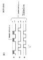
図1には、この色彩変化発光の概念図が示されている。3本の各列は、R(赤)、G(緑)、B(青)を各色彩の光の発光/消灯状態を表しており、横軸は、時間の経過(右側に向かって時間が経過していく)を表す。 FIG. 1 shows a conceptual diagram of the color change light emission. In each of the three columns, R (red), G (green), and B (blue) represent the light emission / extinction state of each color, and the horizontal axis represents the passage of time (time toward the right side). It will pass).
この図1に示すように、色彩変化発光は、RGB等の異なる色彩を所定の順番で交互に「色彩変化」させて発光させる。この色彩の変化がデータを表し、いわゆる自動認識コード等を実現できるものである。 As shown in FIG. 1, the color change light emission causes different colors such as RGB to alternately “color change” in a predetermined order to emit light. This color change represents data, and a so-called automatic recognition code or the like can be realized.
ここで、自動認識コードとは、いわゆるバーコードや、近年のRFID等のように、対象物に付されて、その対象物のIDや、各種情報を担持させるコードを言う。このような自動認識コードによれば、商品(対象物)の情報が瞬時にコンピュータ等に取り込むことができるので、スーパーマーケットのレジ(バーコード)や、物流の分野で広く用いられている。 Here, the automatic recognition code refers to a code that is attached to an object and carries an ID of the object and various kinds of information, such as a so-called bar code or a recent RFID. According to such an automatic recognition code, information on goods (objects) can be instantaneously taken into a computer or the like, and is therefore widely used in the supermarket cash register (barcode) and logistics fields.
バーコード等は、白バーと黒バーとを並べるすなわち空間的に輝度(明度)を変化させてデータを表しているが、上記色彩変化の技術では、時間的に色彩を変化させてデータを表している。 The bar code or the like represents data by arranging white bars and black bars, that is, spatially changing the luminance (brightness). However, in the above color change technique, the data is expressed by changing the color temporally. ing.
明暗波形
このような色彩変化の波形、例えばRの波形に「明暗波形」を重畳させて、データ通信速度の向上を図ることが考えられる。その概念が図1に示されている。
Light / dark waveform It is conceivable to improve the data communication speed by superimposing a “light / dark waveform” on such a color change waveform, for example, an R waveform. The concept is shown in FIG.
明暗波形は、いわば輝度(明度でも良い)の変化であり、このような輝度の変化を用いてデータ通信を行うことは、典型的には光ファイバ等で従来から行われている。また、レーザー光を用いた遠距離通信技術等も知られているが、これも光の輝度変化によって、データを表すものである。 The light / dark waveform is a change in luminance (may be lightness), and data communication using such a change in luminance is typically performed conventionally using an optical fiber or the like. In addition, a long-distance communication technique using laser light is also known, and this also represents data by a change in light brightness.
本実施の形態では、これら輝度(明度)変化を用いたデータ通信を行うための光の強度変化を表す波形を、便宜上「明暗波形」又は「明暗変化パターン」と呼ぶ。 In the present embodiment, a waveform representing a change in the intensity of light for performing data communication using these luminance (brightness) changes is referred to as a “bright / dark waveform” or a “bright / dark change pattern” for convenience.
本実施の形態において特徴的なことは、このように、「色彩変化」の波形の一部又は全部に、「明暗変化」によるデータ通信を重畳させたことである。 What is characteristic in the present embodiment is that data communication by “brightness change” is superimposed on a part or all of the “color change” waveform.
この結果、本願発明者が上記973号特許において既に提案した色彩変化発光を用いて対象物の位置検出を行いつつ、高速なデータ通信を行うことが可能である。 As a result, it is possible to perform high-speed data communication while detecting the position of the object using the color change light emission already proposed by the inventor of the 973 patent.
このとき、「色彩変化」発光が表すデータをX、「明暗波形」信号が表すデータをYとする。通常、「明暗波形」は高周波化が可能なので、表すことができるデータ量について言えば、
データ量(Y) >> データ量(X)
である。
At this time, the data represented by the “color change” emission is X, and the data represented by the “bright / dark waveform” signal is Y. Normally, “bright and dark waveforms” can be high frequency, so speaking of the amount of data that can be represented,
Data volume (Y) >> Data volume (X)
It is.
ここで、本実施の形態では、データ「Y」とデータ「X」との間に所定の関連性を持たせている。このような関連性を持たせることによって、XとYとを結びつけることができ、その結果、対象物の位置の検出とともに、その対象物に関するデータであるYを高速に取得することができたものである。 Here, in the present embodiment, a predetermined relationship is given between the data “Y” and the data “X”. By giving such relevance, X and Y can be linked, and as a result, the position of the object can be detected and Y that is data relating to the object can be acquired at high speed It is.
このような関連性を設ける簡単な例としては、データ「Y」の中に結びついている「X」を記載しておけば良い。又は、データ「X」の中に、結びついている「Y」を記載しておいても良い。 As a simple example of providing such a relationship, “X” linked to data “Y” may be described. Alternatively, “Y” associated with the data “X” may be described.
より正確な処理を行うためには、データ「Y」に所定の数学的処理を施すことによって、「X」を導けるようにXとYの関係を規定しておくことが好適である。このような数学的処理は、特許請求の範囲の「演算処理」の好適な一例に相当する。 In order to perform more accurate processing, it is preferable to define the relationship between X and Y so that “X” can be derived by performing predetermined mathematical processing on the data “Y”. Such mathematical processing corresponds to a preferred example of “arithmetic processing” in the claims.
発光体の構成
さて、図1に示すような、色彩発光中の所定の1色に明暗波形を重畳させることができる発光体の構成図が図2に示されている。
Configuration of the light emitter Well, as shown in FIG. 1, block diagram of a light emitter can superimpose the brightness waveform in a predetermined one color in the color emission is shown in FIG.
図2に示すように、送信対象であるデータXk、Ykが、それぞれ記憶手段10a、10bに格納されている。これらは例えばフラッシュメモリ等であり、別体ではなく、同一の記憶手段を用いても良い。 As shown in FIG. 2, data Xk and Yk to be transmitted are stored in storage means 10a and 10b, respectively. These are, for example, flash memories, and the same storage means may be used instead of separate bodies.
第1制御手段12aは、データXkの内容に基づき、色彩変化パターンを形成し、このパターンに基づき、R、G、Bの発光状態を表す信号を出力する。これらの信号は例えば、「1」なら発光を表し、「0」なら消灯を表す信号である。
The
一方、第2制御手段12bは、データYkの内容に基づき、明暗変化パターンを形成し、このパターンに基づき、Rの発光状態を表す信号を出力する。 On the other hand, the second control means 12b forms a light / dark change pattern based on the contents of the data Yk, and outputs a signal indicating the light emission state of R based on this pattern.
次に、Rドライバ14aは、第1制御手段12a、第2制御手段12b、からのそれぞれの信号を受信し、いずれか一方の信号が「発光」を表す場合(例えば、両信号が「1」である場合)にのみ、赤色LED16aを発光させる。データのコーディング手法によっては、第2制御手段12bからの信号は反転させてからRドライバに供給しても良い。
Next, the
いずれにしても、第1制御手段12aからの信号が「発光」を指示する場合に、第2制御手段12bからの信号が重畳されて、赤色LED16aに加えられる。
In any case, when the signal from the first control means 12a indicates “light emission”, the signal from the second control means 12b is superimposed and applied to the
本実施の形態において特徴的なことは、このようにして、赤色LED16aが発光しているときに、所定のデータを高速で通信するための明暗波形が赤色LED16aの発光に重畳されることである。このような構成によって、フォトダイオード等の受光素子が赤色の光を受光し、明暗波形を取り出すことによって、データYkを高速に受信することが可能になる。その一方、CCD等が赤、青、緑の色彩変化パターンを検出して、データXkを取得する。
What is characteristic in the present embodiment is that, in this way, when the
Bドライバ14bは、第1制御手段12aからの信号に基づき、所定の色彩変化パターンで、青色LED16bを駆動し、発光、消灯を行わせる。同様に、Gドライバ14cは、第1制御手段12aからの信号に基づき、所定の色彩変化パターンで、緑色LED16cを駆動し、発光、消灯を行わせる。
Based on the signal from the first control means 12a, the
なお、図2の例では、Xk、Ykのデータそのものを格納しているが、発光パターンである明暗波形及び色彩変化パターンを格納しても良い。また、図2の記憶手段10a10bは一体に構成しても良い。また、第1制御手段12a、第2制御手段12bも単一のプロセッサが双方の動作を実現することも好適である。更に、図2では、R、G、Bの各LEDを用いる例を示したが、いわゆるフルカラーLEDを用いて3色の光を単一の発光手段で発光させてもかまわない。
In the example of FIG. 2, the Xk and Yk data itself is stored, but a light / dark waveform and a color change pattern, which are light emission patterns, may be stored. Further, the storage means 10a10b in FIG. 2 may be configured integrally. In addition, it is also preferable that the
1−2 複数の発光体
特に、上記色彩変化発光の発光体が1〜nまでn個存在したとき、データ「Yk」から一意的にデータ「Xk」が導き出せるようにしておけば、どのXkとどのYkが組み合わせられるか識別することができる。ここで、kは1〜nの整数である。
1-2 Multiple light emitters, in particular, when there are n color-
そのような演算処理は種々存在する。例えば、ハッシュ関数を用いて、Ykから、Xkを求めることも好適である。その他、種々の関数を利用することが可能である。用途によっては、その関数処理を秘密化しておき、暗号通信のごとき構成を採用することも好適である。 There are various types of such arithmetic processing. For example, it is also preferable to obtain Xk from Yk using a hash function. In addition, various functions can be used. Depending on the application, it is also preferable to keep the function processing secret and adopt a configuration such as encryption communication.
ところで、色彩変化で表されるデータ「X」は通常その発光体(又は、発光体の付された物体)固有のIDであるケースが多い。これは、上述したように、色彩変化の変化速度をCCD等でキャプチャするので、高速なデータ通信が困難なため、ID程度の小規模なデータとして利用することが多いためである。 By the way, the data “X” represented by the color change is usually an ID unique to the light emitter (or an object to which the light emitter is attached). This is because, as described above, since the change speed of the color change is captured by a CCD or the like, high-speed data communication is difficult, and therefore, it is often used as small-scale data such as an ID.
このため、そのIDに対応する一定の発光パターンを繰り返し発光するように構成することが好適である。 For this reason, it is preferable that the light emission pattern corresponding to the ID is repeatedly emitted.
1−3 データ「Y」を表す明暗波形の埋め込みの手法
したがって、その発光パターンの中では、Rが現れる回数とタイミングは予め決定されている。これを考慮すれば、例えば、Rに「明暗波形」を重畳する場合、通常、一回のRの発光を単位として明暗波形を埋め込むか、又は、上記パターンの1サイクルを一つの単位として明暗波形を埋め込むか、のいずれかとすることがシンプルで好適である。
1-3 Method of Embedding Bright / Dark Waveform Representing Data “Y” Therefore, in the light emission pattern, the number and timing of R appearing are determined in advance. Considering this, for example, when superimposing a “bright / dark waveform” on R, the bright / dark waveform is usually embedded with one R emission as a unit, or one cycle of the above pattern as one unit. It is simple and preferable to embed one of them.
図1では、1回のR発光毎に、データ「Y」を表す明暗波形を埋め込んでいく例が示されている。また、例えば、パターンの1サイクル上でR発光が12回出現する場合、波形データ「Y」を12分割して各Rに重畳することが好適な一例として考えられる。また、6分割して、R発光2回あたり1回データを重畳させることも好適である。 FIG. 1 shows an example in which a light and dark waveform representing data “Y” is embedded for each R emission. Further, for example, when R light emission appears 12 times in one cycle of the pattern, it is conceivable as a preferred example that the waveform data “Y” is divided into 12 and superimposed on each R. It is also preferable to divide the data into 6 and superimpose data once every 2 R emission.
なお、この「R発光2回あたり1回データを重畳させる」という例は、請求の範囲の記載において、「発光強度を制御する対象である発光手段が発光している期間のうち、一部の期間においてのみその発光強度を制御する」という動作の一例に相当する。 In addition, this example of “superimposing data once every two R emission times” refers to “a part of the period during which the light emitting means that is the target for controlling the emission intensity emits light” in the claims. This corresponds to an example of the operation of “controlling the light emission intensity only during the period”.
逆に、データ「Y」を24分割して、それらをR発光毎に埋め込めば、発光パターンの2サイクルで、データ「Y」を表すことが可能である。この場合も、パターンの1サイクル上でR発光が12回出現する場合を前提としている。 On the other hand, if the data “Y” is divided into 24 parts and embedded in each R emission, the data “Y” can be represented by two cycles of the emission pattern. Also in this case, it is assumed that R light emission appears 12 times on one cycle of the pattern.
1−3−1 1回のR発光に対して、データ「Y」を表す明暗波形を埋め込む場合
データ「Y」のデータ量にも依存するが、一般的な商品管理情報の場合は、1回のR発光中で、データ「Y」を全て埋め込める場合も多い。なお、データ量が多い場合は、後述する図4に示すように、重畳するRの発光時間を他に比べて長くとることも大変好ましい。
1-3-1 When embedding a light / dark waveform representing data “Y” for one R emission, depending on the data amount of data “Y”, it is once in the case of general product management information. In many cases, all the data “Y” can be embedded during the R emission. When the amount of data is large, as shown in FIG. 4 to be described later, it is also very preferable to make the light emission time of the superimposed R longer than others.
色彩変化パターンを利用する場合は、各色彩の発光時間の自由度が高いので、送信するデータ量に応じて、発光時間を調整することができる。言い換えれば、「色彩変化」の場合、色彩の変化・遷移に基づき「X」を表し、また検知を行うので、読み取られるデータは、各色彩の発光時間には直接依存しないという性質を有するためである。なお、このように、各色彩の発光時間の変動がデータに影響を及ぼさないことは、色彩変化発光の良好な特性の一つである。 When the color change pattern is used, the light emission time can be adjusted according to the amount of data to be transmitted because the light emission time of each color has a high degree of freedom. In other words, in the case of “color change”, “X” is expressed based on the change / transition of the color, and detection is performed, so that the read data has a property that it does not directly depend on the emission time of each color. is there. In addition, it is one of the favorable characteristics of the color change light emission that the variation in the light emission time of each color does not affect the data in this way.
1−4 埋め込む対象の色彩
これまでは、色彩のRの発光に明暗波形を埋め込む例を示したが、波形データを重畳する色彩は必ずしもRである必要はない。BやGに埋め込むことも好適である。
1-4 Colors to be Embedded So far, an example has been shown in which a bright and dark waveform is embedded in the R emission of the color, but the color on which the waveform data is superimposed does not necessarily have to be R. It is also preferable to embed in B or G.
1−4−1 3色のうちいずれか1色に対する埋め込み
このように、BやGに明暗波形を埋め込んでもかまわない。更に、3色として、本例のようにRGBを選択する必要はなく、C(シアン)、M(マゼンタ)Y(イエロー)等の色彩を用いることも好適である。また、他の任意の3色でもかまわない。
1-4-1. Embedding to any one of the three colors In this way, a bright and dark waveform may be embedded in B or G. Further, it is not necessary to select RGB as the three colors as in this example, and it is also preferable to use colors such as C (cyan), M (magenta), and Y (yellow). Also, any other three colors may be used.
また、色彩の数に特段の制限はない。環境によっては、2色でも良いし、条件さえ許せば4色以上の色彩を用いてもかまわない。 There is no particular limitation on the number of colors. Depending on the environment, two colors may be used, and four or more colors may be used if conditions permit.
更に、必ずしも可視光に限られず、赤外光や紫外光を含む色彩を利用することも好適である。この場合は、赤外線や紫外線も色彩の1種として考えている。広く色彩とは「波長」であると考えても良い。なお、赤外線や紫外線を用いる場合は、それらの光を検知できるセンサ、CCD等を用いることは言うまでもない。 Furthermore, it is not necessarily limited to visible light, and it is also preferable to use colors including infrared light and ultraviolet light. In this case, infrared rays and ultraviolet rays are also considered as one type of color. Widely, it may be considered that a color is a “wavelength”. In addition, when using infrared rays or ultraviolet rays, it goes without saying that a sensor capable of detecting such light, a CCD, or the like is used.
1−5 3色全色に対する埋め込み
更に、1色にだけでなく全色に「明暗波形」を重畳することも好適である。
1-5 Embedding to all three colors Further, it is also preferable to superimpose a “bright / dark waveform” on all colors as well as on one color.
この場合、明暗波形を受光する素子は、3波長を受光可能な素子を利用することが必要である。このような素子の例が、次に述べる図3の受光素子として示されている。 In this case, it is necessary to use an element capable of receiving three wavelengths as an element that receives light and dark waveforms. An example of such an element is shown as the light receiving element in FIG.
なお、3波長の光を受光する単一の素子の代わりに、複数の受光素子をそれぞれに光路分割手段とともに配置し、各波長光をそれぞれ分担して受け取る方式なども考えられる。 In addition, instead of a single element that receives light of three wavelengths, a system in which a plurality of light receiving elements are arranged together with an optical path dividing unit, and each wavelength light is shared and received may be considered.
1−6 複数の発光体からの光を受光する装置構成(概念図)
図3には、上記複数の光源(発光体)からの複数投光を受光することができる受光光学系の概念図、その受光装置の概念図が示されている。
1-6 Device configuration (conceptual diagram) for receiving light from a plurality of light emitters
FIG. 3 shows a conceptual diagram of a light receiving optical system capable of receiving a plurality of light projections from the plurality of light sources (light emitters) and a conceptual diagram of the light receiving device.
図3に示すように、まず、結像光学系20によって、色彩発光による光はCCD等のエリアセンサ22上に結像する。
As shown in FIG. 3, first, light by color light emission is imaged on an
ここで発光体Aの像はA’、発光体Bの像はB’の位置に結像する。この位置はエリアセンサ22の出力信号を解析することによって容易に認識することができる。これは、すなわち、画像処理によって、所定の色彩変化が生じている領域・位置を上記A’、B’として認識することである。同時に、各像A’、B’の色彩変化から、色彩変化によって表されたデータ、すなわちXを認識することができる。
Here, the image of the light emitter A is formed at the position A ', and the image of the light emitter B is formed at the position B'. This position can be easily recognized by analyzing the output signal of the
この動作は、色彩変化発光によって、発光体の位置を求める動作であり、本願発明者が既に特許出願をした内容である。 This operation is an operation for obtaining the position of the illuminant by color change light emission, and has been already filed by the inventor of the present application.
簡単に言えば、図示されていないデータ復号手段が、画像処理を行うことによって、所定の色彩変化を生じている領域を検出して、発光体の位置を求める動作である。このようなデータ復号手段は、コンピュータ等を用いて構成することが好ましいが、画像処理を行い、色彩があるパターンで変化していく領域を見つけ出すことができる手段であればどのような手段でもかまわない。また、このデータ復号手段は、この検出した色彩の変化パターンからそのパターンが表すデータ、すなわち上述したデータXを復号する。この結果、データ復号手段は、発光体の位置を求めるとともに、その発光体のID(すなわちデータX)を得ることができる。 Briefly speaking, this is an operation in which a data decoding means (not shown) detects an area where a predetermined color change has occurred by performing image processing, and obtains the position of the light emitter. Such data decoding means is preferably configured using a computer or the like, but any means can be used as long as it can perform image processing and find an area where colors change in a certain pattern. Absent. The data decoding means decodes data represented by the pattern, that is, the data X described above, from the detected color change pattern. As a result, the data decoding means can obtain the position of the light emitter and obtain the ID (that is, data X) of the light emitter.
更に、本実施の形態において特徴的なことは、光学系内に設けられたハーフミラー24の光路分割手段で、一部の光がエリアセンサ22ではない一般的な受光素子26に導かれていることである。そして、この受光素子26によって、上述した明暗波形が検出されるのである。
Furthermore, what is characteristic in the present embodiment is the optical path dividing means of the
この受光素子26は、上述したように、フォトダイオード、フォトトランジスタなどの一般的な光センサが用いられる。なお、本例では、R光に明暗波形が重畳されているため、受光素子26の前面には、Rの波長付近の光のみを透過する色彩フィルタが設けられており、ノイズの影響を受けにくく構成している。 As the light receiving element 26, a general optical sensor such as a photodiode or a phototransistor is used as described above. In this example, since the bright and dark waveform is superimposed on the R light, a color filter that transmits only light in the vicinity of the R wavelength is provided on the front surface of the light receiving element 26 and is not easily affected by noise. It is composed.
さて、受光素子26は、上述のごとくフォトダイオード等の光電変換素子であり、信号上に重畳された「明暗波形」に対して広範囲な周波数帯域にわたって光電変換を行う。ごく一般的なフォトダイオード等を用いれば、数MHz以上の周波数の波形変化を検知することができる。そのため、上述した色彩変化によるデータの通信(数10Hz程度の周波数による通信)に比して、はるかに大量のデータ通信を行うことができる。 The light receiving element 26 is a photoelectric conversion element such as a photodiode as described above, and performs photoelectric conversion over a wide frequency band on the “bright and dark waveform” superimposed on the signal. If a very common photodiode or the like is used, a change in waveform having a frequency of several MHz or more can be detected. Therefore, a much larger amount of data communication can be performed as compared with the above-described data communication by color change (communication at a frequency of about several tens of Hz).
この受光素子26上では発光体Aの光像はA’’となり(図3参照)、受光素子26により光電変換された電気信号(波形)をデコード処理すれば、原データ「YA」が得られる。このように、光の明暗波形で、データを通信する技術は、従来から光ファイバ等で用いられているので、その技術をそのまま利用すれば良い。より広くとらえれば、信号のON/OFFでデジタルデータを送る技術は、CDやDVDその他の広い分野で利用されているので、目的やデータ量等に応じてそれらの符号化・復号化技術、変調・復調技術を用いれば良い。 On this light receiving element 26, the light image of the illuminant A becomes A ″ (see FIG. 3). If the electric signal (waveform) photoelectrically converted by the light receiving element 26 is decoded, the original data “Y A ” is obtained. It is done. As described above, a technique for communicating data using a light / dark waveform of light is conventionally used in an optical fiber or the like, and therefore, the technique may be used as it is. From a broader perspective, the technology for sending digital data by turning the signal ON / OFF is used in a wide range of fields such as CDs, DVDs, etc.・ Demodulation technology should be used.
次に、発光体Bの光像は受光素子26上でB’’となり(図3参照)、これによって得られた電気信号をデコード処理すれば、原データ「YB」が得られる。 Next, the light image of the illuminant B becomes B ″ on the light receiving element 26 (see FIG. 3), and if the electric signal obtained thereby is decoded, the original data “Y B ” is obtained.
なお、本例のように複数の「明暗波形」が同時に発光を行い、それらを事実上同時に受信する場合は、一般的な変調・復調技術を利用して、それぞれの発光信号を識別することが好適である。例えば、上記発光体Aは、明暗波形を1000kHzで振幅変調して出力し、発光体Bは明暗波形を1200kHzで振幅変調して出力することが好適な一例である。このように発光信号を変調しておき、受光側で1000kHzで復調すれば発光体Aの信号が得られ、受光側で1200kHzで復調すれば発光体Bの信号が得られることは容易に理解できよう。 In addition, when a plurality of “bright and dark waveforms” emit light at the same time as in this example and receive them substantially simultaneously, it is possible to identify each light emission signal using a general modulation / demodulation technique. Is preferred. For example, the light emitter A preferably outputs a light / dark waveform with amplitude modulation at 1000 kHz, and the light emitter B outputs a light / dark waveform with amplitude modulation at 1200 kHz. It is easy to understand that the signal of the light emitter A can be obtained by modulating the light emission signal and demodulating at 1000 kHz on the light receiving side, and the signal of the light emitter B can be obtained by demodulating at 1200 kHz on the light receiving side. Like.
その他、既に知られている様々な変調・復調方式を応用すれば、数多くの発光体を容易に分離可能であることは明らかである。 In addition, it is obvious that many light emitters can be easily separated by applying various known modulation / demodulation methods.
ここで、先に述べたように、本実施の形態では、明暗波形から得られたYA,YBから一意的にXA,XBが包含されていることが判明するので、YAはXAと関連づけられていることが認識される。更に、YAは、CCD上のXAの位置と関連づけられて認識される。 Here, as previously described, in this embodiment, Y A obtained from the light and dark waveform, Y B from uniquely X A, since it is found that the X B are included, Y A is it is recognized that associated with the X a. Furthermore, Y A is recognized in association with the position of X A on the CCD.
同様にYBはXBと関連づけられ、更にCCD上のXBの位置と関連づけられて認識される。 Similarly, Y B is associated with X B and further recognized with respect to the position of X B on the CCD.
本実施の形態では、例として「YA,YBから一意的にXA,XBが包含されている」ことを挙げたが、YA,YBから一意的にXA,XBが求められ関連性を認識できれば、どのような手段を用いても良い。 In this embodiment, as an example has been given that "Y A, uniquely X A from Y B, the X B are included", Y A, uniquely X A from Y B, the X B Any means may be used as long as it is required and the relevance can be recognized.
ところで、明暗波形を受光する受光素子26上では図3に示すように、発光体A、発光体Bの受光素子に対する像であるA’’,B’’が同時に受光されるので、受光素子26で得られる受光信号は両者の波形信号の和となる。しかしながら、例えば、通常のラジオ放送の信号の検波等と同様に、ベース周波数を異ならせておく等の方式で容易に分離可能であり、ABの同時受信は分離に障害とならない。例えば、上述したように、搬送周波数を異なる周波数として変調を行い、受信した信号から所定の搬送周波数の信号のみを復調・検波することによって、発光体Aからの信号と、発光体Bからの信号とを容易に分離することができる。 By the way, on the light receiving element 26 that receives the light and dark waveform, as shown in FIG. 3, A ″ and B ″, which are images of the light emitting body A and the light emitting body B with respect to the light receiving elements, are simultaneously received. The received light signal is the sum of both waveform signals. However, for example, similarly to detection of a signal of a normal radio broadcast, it can be easily separated by a method such as different base frequencies, and simultaneous reception of AB does not hinder separation. For example, as described above, by modulating the carrier frequency as a different frequency and demodulating / detecting only the signal of a predetermined carrier frequency from the received signal, the signal from the light emitter A and the signal from the light emitter B Can be easily separated.
1−7 発光時間の調整
図4には図1等で既に説明したように、Rの一部に明暗波形が重畳されている一例を示す説明図である。縦軸は、光の強度(輝度)であり、いわゆる明暗を表す。横軸は時間の経過を表し、左から右へ時間が進む。
1-7 Adjustment of Light-Emitting Time FIG. 4 is an explanatory diagram showing an example in which a bright and dark waveform is superimposed on a part of R as already described with reference to FIG. The vertical axis represents light intensity (luminance) and represents so-called light and dark. The horizontal axis represents the passage of time, and time advances from left to right.
先に述べたように、色彩変化発光によるID検知は、色彩変化(遷移)を検出してその順番でコードを表す考え方に基づくものであり、発光の時間そのものには特段の規定はない。そのため、一部の発光時間が長くなってもかまわない。色彩変化発光では、各色彩の発光時間を自由に選ぶことができるように構成したので、環境(明るい、暗い、迷光が多い、迷光が少ない、周囲の輝度変化が激しい・・・など)に応じて、発光時間を選択でき、且つ、送信中でもリアルタイムに調整できるので、効率の良い正確な通信が可能である。 As described above, the ID detection based on the color change light emission is based on the concept of detecting the color change (transition) and representing the code in the order, and the light emission time itself has no special provision. Therefore, a part of the light emission time may be longer. In color change light emission, it is configured so that the light emission time of each color can be freely selected, so depending on the environment (bright, dark, a lot of stray light, little stray light, intense brightness changes in the surroundings, etc.) Since the light emission time can be selected and adjusted in real time even during transmission, efficient and accurate communication is possible.
そこで、本実施の形態でも、例えば、Rの発光時間を一時的に又は恒常的に調整(長く)することができる。これは、請求の範囲に記載の、第1の制御手段が、第2の制御手段がいずれかの発光手段を制御している場合、「発光手段の発光状態を継続させる」という動作の好適な一例に相当する。 Therefore, also in this embodiment, for example, the R emission time can be adjusted (longer) temporarily or permanently. This is because the first control means described in the claims is suitable for the operation of “continuing the light emission state of the light emission means” when the second control means controls any of the light emission means. It corresponds to an example.
図4では、Rの一箇所の発光時間を延ばし、その部分に波形を重畳させる例を示している。 FIG. 4 shows an example in which the light emission time at one location of R is extended and the waveform is superimposed on that portion.
1−8 IR重畳発光
さて、図4や図1等で示してきたように、色彩変化発光で用いている色彩の一部又は全部に明暗波形を重畳する例を説明してきた。しかし、色彩変化発光で用いる色彩(ここではRGB)以外に、明暗波形を伝送する色彩として赤外光(IR)を用いて、このIRを前記RGBに重畳させることも好適である。
1-8 IR superimposition light emission Now, as shown in FIG. 4 and FIG. 1 etc., the example which superimposes a light-dark waveform on a part or all of the color used by color change light emission has been demonstrated. However, it is also preferable to use infrared light (IR) as a color for transmitting light and dark waveforms in addition to the color used for color change light emission (RGB here), and to superimpose this IR on the RGB.
この場合、受光側では受光素子26がIRの受光素子として構成することが好適である。また、受光素子26の前面の色彩フィルタ28をIRフィルタ等に置き換えることが好適であろう。 In this case, it is preferable that the light receiving element 26 is configured as an IR light receiving element on the light receiving side. It may be preferable to replace the color filter 28 on the front surface of the light receiving element 26 with an IR filter or the like.
一方、発行側では、色彩変化発光を重畳した赤外光(IR)を、RGB等の色彩変化に用いるRGB等の色彩と同じ位置から発光するように工夫する必要がある。 On the other hand, on the issue side, it is necessary to devise so that infrared light (IR) superimposed with color change light emission is emitted from the same position as the color such as RGB used for color change such as RGB.
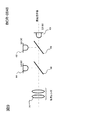
図5には、このようにIRを、色彩変化に用いるRGB等と重畳して同位置から発光させるように構成した光学系(発光体)の構成図が示されている。この図5の例では、IRの発光源以外にRGB発光源(LED等)が厳密に位置関係を同じくするために光軸上にハーフミラーを設けて、外部から見て、両者の光軸が一致するように構成している。 FIG. 5 shows a configuration diagram of an optical system (light emitting body) configured to emit IR light from the same position by superimposing IR and RGB used for color change in this way. In the example of FIG. 5, a half mirror is provided on the optical axis so that the RGB light sources (LEDs, etc.) have the same positional relationship in addition to the IR light source. Configured to match.
図5に示すように、まず、赤外線発光素子30が明暗波形の信号を受信して、明暗波形が施された赤外光を発する。なお、図示されてはいないか、図5の赤外線発光素子30には、その赤外線発光素子30を駆動するドライバが接続されており、更にそのドライバには、図2における第2制御手段12bの信号が供給されている。このような構成によって赤外線発光素子30から発せられた赤外線は、投光レンズを介して外部に放出される。 As shown in FIG. 5, first, the infrared light emitting element 30 receives a light / dark waveform signal and emits infrared light with the light / dark waveform. Although not shown, a driver for driving the infrared light emitting element 30 is connected to the infrared light emitting element 30 in FIG. 5, and further, a signal of the second control means 12b in FIG. 2 is connected to the driver. Is supplied. The infrared rays emitted from the infrared light emitting element 30 with such a configuration are emitted to the outside through the light projecting lens.
本実施の形態において特徴的なことは、この赤外線の光軸の途中に45度傾いたハーフミラー34が設けられていることである。このハーフミラー34は、図5のRGB3色発光LED36が発する色彩変化の光を、上記赤外線と同方向に反射する。
What is characteristic in the present embodiment is that a
この結果、色彩変化に用いるRGB光を、赤外線と同位置から同方向に放射することが可能である。 As a result, RGB light used for color change can be emitted in the same direction from the same position as infrared rays.
なお、図5のRGB3色発光LED36は、図2におけるLED16a、16b、16cと同等の役割を果たす。また、図2と同様に、このRGB3色発光LED36にも、所定のドライバが接続されており、このドライバがRGB3色発光LEDを駆動する。そして、このドライバには図2と同様に第1制御手段が接続される。図示されていないその他の構成も図2と同様である。
Note that the RGB three-color LED 36 in FIG. 5 plays the same role as the
このような図5による発光形態の様子が図6のタイムチャートに示されている。 The state of the light emission form according to FIG. 5 is shown in the time chart of FIG.
この図6では、上段から、IR(赤外光)、R、G、Bの各光の発光強度(輝度)変化が示されており、横軸は時間の経過である。左から右に向かって時間が経過している。 In FIG. 6, the change in emission intensity (luminance) of each light of IR (infrared light), R, G, and B is shown from the upper stage, and the horizontal axis represents the passage of time. Time has passed from left to right.
さて、図6に示すように、色彩変化で用いるRGB以外の発光であるIR光はそのままで明暗波形を伝えることが可能である。言い換えれば、RGBとは形式的には独立してデータ通信を行える。ただし、下記に述べるように、両者には一定の関連性を備えさせているので、発光体の位置と、IRで送信するデータとを組み合わせて認識することが可能である。 Now, as shown in FIG. 6, it is possible to transmit a light / dark waveform without changing the IR light which is light emission other than RGB used for color change. In other words, data communication can be performed formally independent of RGB. However, as described below, since both have a certain relationship, the position of the light emitter and the data transmitted by IR can be recognized in combination.
1−9 IR重畳発光受光部
明暗波形を乗せる対象としてIRを利用し、このIRを色彩変化の光(例えばRGB)と重畳して発光させる場合を上で説明したが、これを受光する装置の構成を説明する。
1-9 IR Superimposing Light-Emitting Light-Receiving Unit The case where IR is used as an object on which a light and dark waveform is placed and this IR is superimposed on light of color change (for example, RGB) to emit light has been described above. The configuration will be described.
図7には、上記IR重畳発光を受光する受光部の構成の一例を示す構成図が示されている。上述した図3と同様に、光軸上に設けられたハーフミラー40で光路が分割され、一部の光は、エリアセンサ42上に導かれ、他の一部の光は受光素子44に導かれる。このような点では、図3と同様である。
FIG. 7 is a configuration diagram illustrating an example of a configuration of a light receiving unit that receives the IR superimposed light emission. Similar to FIG. 3 described above, the optical path is divided by the
ここで、受光素子44上には赤外透過フィルタ46を設け、赤外線のみを受光素子44に供給することが分離の点で好ましい。同様に、エリアセンサ42上には赤外カットフィルタ48を設けておけば、赤外光と色彩変化光との分離がより確実になるので好ましい。
Here, it is preferable in terms of separation to provide an infrared transmission filter 46 on the light receiving element 44 and supply only infrared light to the light receiving element 44. Similarly, it is preferable to provide an infrared cut filter 48 on the
もちろん、受光素子44が、赤外線のみに感度を有し、通常の可視光には全く反応しない特性を予め有している場合は、上記赤外透過フィルタ46は不要である。同様に、エリアセンサが可視光のみに感度を有し、赤外光を全く検知しないのであれば、上記赤外カットフィルタ48は省略することができる。 Of course, when the light receiving element 44 has a characteristic that is sensitive only to infrared rays and does not react to normal visible light at all, the infrared transmission filter 46 is unnecessary. Similarly, if the area sensor is sensitive only to visible light and does not detect infrared light at all, the infrared cut filter 48 can be omitted.
このような構成によって、受光素子44から赤外光に乗った明暗波形の信号を得て、この信号をデコードすることによって、データ「Yk」を得ることができる。また、エリアセンサ42の出力する画像信号から、所定の色彩変化パターンが生じている領域の位置(ポジション:図7参照)を検知することができ、且つ、検出した色彩変化パターンをデコードすることによって、データ「Xk」を得ることができる。
With such a configuration, it is possible to obtain data “Yk” by obtaining a signal of a bright and dark waveform riding on infrared light from the light receiving element 44 and decoding this signal. Further, it is possible to detect the position (position: see FIG. 7) of an area where a predetermined color change pattern is generated from the image signal output from the
1−10 データ「X」とデータ「Y」の関係
以上述べたように、本発明は、色彩変化パターンによる通信に明暗波形による通信を組み合わせて、データ速度の向上を図ることができる。データ速度は、明暗波形による通信の方が大きいので、送ろうとする主たるデータはデータ「Y」に乗せて通信されることが多くなると考えられる。
1-10 Relationship between Data “X” and Data “Y” As described above, the present invention can improve data rate by combining communication using a color change pattern and communication using a light / dark waveform. Since the data rate is higher in the communication using the light and dark waveform, it is considered that the main data to be transmitted is often transmitted on the data “Y”.
この主たるデータとしては、例えば、IDや固定された同一のファイルデータのように、同一で変化しないものを繰り返し送出するケースと、いわゆる汎用の通信のように時間の経過とともに不定に変化するケースと、の2種のケースが考えられる。 As this main data, for example, a case of repeatedly sending the same and non-changeable data such as an ID or a fixed same file data, and a case of changing indefinitely with the passage of time like so-called general-purpose communication There are two possible cases.
いずれのケースも、位置関係(すなわち、データ「Xk」側のデータ)との合致が得られることが本発明では重要な点である。したがって、いずれのケースでも「Y」について所定の処理を行うことによって「X」が得られる必要がある。 In any case, it is important in the present invention that a match with the positional relationship (that is, data on the data “Xk” side) is obtained. Therefore, in any case, “X” needs to be obtained by performing predetermined processing on “Y”.
(1)「Y」として送信したいデータが単一のデータの繰り返しの場合
例えば、
「X」=「123」、
「Y」を用いて送出したいデータが=「abcdefghijklmn」
の場合を検討しよう。
(1) When data to be transmitted as “Y” is a single data repetition For example,
“X” = “123”,
The data to be sent using “Y” = “abcdefghijklmn”
Let's consider the case.
さて、「Y」は、「X」と関連づけるため、「Y」を、「123 abcdefghijklmn」と設定し、これを繰り返して送信することが簡単な例の一つとして考えられる。 Since “Y” is associated with “X”, “Y” is set to “123 abcdefghijklmn”, and this is repeatedly transmitted as one simple example.
この場合、「Y」は、「123abcdefghijklmn123abcdefghijklmn…」と一定周期のデータが送られることになる。 In this case, “Y” is data having a fixed period such as “123abcdefghijklmn123abcdefghijklmn...”.
このように、一定周期毎に「X」である「123」を含ませたデータを作成し、所定のルールを定めて「123」を数学的に導く手法を採用することが好ましい。簡単な例で行うには、この場合は数字を「X」と見なし、それ以外のアルファベット等が送信者が送信したいデータであると認定することが考えられる。言い換えれば、Xとして使用できるパターン、Yとして利用できるパターンを、それぞれ予め決めておけば、受信側では容易にそれらを分離することが可能である。 As described above, it is preferable to adopt a method of creating data including “123” that is “X” at regular intervals, mathematically deriving “123” by defining a predetermined rule. In a simple example, in this case, it is considered that the number is regarded as “X” and other alphabets are recognized as data that the sender wants to transmit. In other words, if a pattern that can be used as X and a pattern that can be used as Y are determined in advance, the receiving side can easily separate them.
所定のデータ中に他のデータを埋め込み、後にそのデータを取り出す数学的な手法は種々知られているので、従来から知られているそのような既存の方法を採用することが好適である。 Since various mathematical methods for embedding other data in predetermined data and extracting the data later are known, it is preferable to adopt such an existing method known from the past.
例えば、CRC演算のような所定の巡回演算式を決めておき、その計算式で求めた数値が「X」であるように、一定周期毎にチェックデータを付加していくことなどが好適である。その他、既存の音声データや画像データ中に所定のIDを埋め込んでおき、著作権のチェック等も行われているが、そのようなデータの埋め込み技術を利用することも好適である。 For example, it is preferable to determine a predetermined cyclic calculation formula such as CRC calculation, and add check data at regular intervals so that the numerical value obtained by the calculation formula is “X”. . In addition, a predetermined ID is embedded in existing audio data and image data, and copyright is checked. It is also preferable to use such data embedding technology.
(2)「Y」として送信したいデータが、汎用の通信データであった場合。 (2) The data to be transmitted as “Y” is general-purpose communication data.
また「Y」として送信したい対象がいわゆる汎用の通信(電話通信、ニュース通信、インターネット上のメールの通信等)であった場合は、同一データの繰り返しは期待できない。 In addition, when the object to be transmitted as “Y” is a so-called general-purpose communication (telephone communication, news communication, mail communication on the Internet, etc.), it is impossible to expect the same data to be repeated.
この場合も、例えば一定の周期毎に
123abcdefghijklmn
123fghijklmnopqrs
123xyzabcdefghijk…
のように、所定のデータ(例えば「Xk」そのもの、又は、「Xk」に所定の演算処理を施したもの)を挿入して、「Yk」を構成する等の方法が考えられる。上の例では、「123」が「Xk」の一例に相当する。上の例では、「Xk」そのもの(「123」)を埋め込む例を説明したが、所定の演算処理を加えたものを挿入していくことも好ましい。
Also in this case, for example, 123 abcdefghijjklmn every fixed period
123fghijklmnopqrs
123xyzabcdefghijj ...
As described above, a method of configuring “Yk” by inserting predetermined data (for example, “Xk” itself or a data obtained by performing a predetermined arithmetic process on “Xk”) is conceivable. In the above example, “123” corresponds to an example of “Xk”. In the above example, the example of embedding “Xk” itself (“123”) has been described, but it is also preferable to insert the one added with a predetermined arithmetic processing.
(3)色彩変化パターンの時間変化
一方、色彩発光パターンを順次変化させていくことも考えられる。これは、すなわち、Xkを順次変えていくことを意味する。例えば、「123」→「321」→「231」のように所定の条件の下で、Xkを順次変化させていくのである。
変化のさせ方にもよるが、どの部分がXkかを識別することが複雑になる場合も想定される。その場合、例えば「Y」に、一定周期でマーカー符号(例えば「111」)を付加することでデータの切れ目、ひいてはXkの位置を明示的に示すことが可能である。そのような例を以下に示す。
(3) Temporal change of color change pattern On the other hand, it is also conceivable to change the color emission pattern sequentially. This means that Xk is sequentially changed. For example, Xk is sequentially changed under predetermined conditions such as “123” → “321” → “231”.
Although depending on how to change, it may be complicated to identify which part is Xk. In this case, for example, by adding a marker code (for example, “111”) to “Y” at a fixed period, it is possible to explicitly indicate the break of data, and thus the position of Xk. Such an example is shown below.
111123abcdefghijklmn
111321fghijklmnopqrs
111231xyzabcdefghijk…
このように、区切りを表すマーカー符号とともに、Xkを順次変化させていったものを互いに隣接して挿入した。その結果、マーカー符号(「111」)を検出することによって、それに隣接している「Xk」を順次変化させていったものを検出することができる。そして、残りの部分を「Yk」であると認識することができる。
111123abcdefghijjklmn
1111321fghijklmnopqrs
111231xyzabcdefghijk ...
In this way, the marker codes representing the breaks were inserted adjacent to each other with Xk being sequentially changed. As a result, by detecting the marker code (“111”), it is possible to detect what has sequentially changed “Xk” adjacent thereto. The remaining portion can be recognized as “Yk”.
この結果、容易に「Xk」、「Yk」を認識することが可能である。このように、Xkを順次変化させていくことは、例えばセキュリティ上大きな意味を有する。 As a result, “Xk” and “Yk” can be easily recognized. In this way, sequentially changing Xk has a significant meaning in terms of security, for example.
(4) Xkの変化
本実施の形態では、XkとYkとに関連性を持たせることによって、どのXkとYkとが組になるか知ることができた。その結果、Xkから位置とID等のデータを得ることができるとともに、Ykから比較的大量のデータを得ることができる。言い換えれば、高速な通信を行うことができる。
(4) Change in Xk In the present embodiment, it is possible to know which Xk and Yk are paired by making Xk and Yk relevant. As a result, data such as position and ID can be obtained from Xk, and a relatively large amount of data can be obtained from Yk. In other words, high-speed communication can be performed.
しかし、用途によっては、Xkは例えば、ID等として利用されるため、第3者にわかりにくくすることが望まれる場合がある。そこで、上述した(3)で示した例ではXkを順次変化させて、Xkの値の真の値がどれかわかりにくくなるように設定したのである。この結果、セキュリティの点から好ましい結果を得ることができる。 However, depending on the application, since Xk is used as, for example, an ID, it may be desired to make it difficult for a third party to understand. Therefore, in the example shown in the above (3), Xk is sequentially changed so that the true value of the value of Xk becomes difficult to understand. As a result, a preferable result can be obtained from the viewpoint of security.
したがって、正当な利用者は、Xkがどのように変化していくかある程度知っている必要がある。少なくとも、変化したXk’の値が、本来はXkであることが判明する程度に、変化の手順を理解していく必要がある。 Therefore, a legitimate user needs to know to some extent how Xk changes. It is necessary to understand the change procedure at least to the extent that the changed value of Xk ′ is originally found to be Xk.
上で述べた例は、原Xkの桁を組み替えていく、という「変化」のさせ方を採用している。この変化のさせ方は種々のバリエーションが考えられるが、
・組み替えはランダムに行わせれば、より他人にわかりにくくなる。
・正しい真のXkの値は、利用する対象物の数の個数分必要であるが、その各真の値は、互いにそこに含まれる各桁の数が重複しないことが好ましい。例えば、X1は、「123」であり、X2は「456」であり、X3は、「789」等のように選択する。
The example described above adopts the “change” method of rearranging the digits of the original Xk. There are various ways to change this,
・ If you rearrange them randomly, it will be harder for others to understand.
The correct true Xk value is required by the number of objects to be used, but it is preferable that the true values of the true values do not overlap with each other. For example, X1 is “123”, X2 is “456”, X3 is selected as “789”, and the like.
このように設定すれば、X1である「123」の桁を組み替えても、他のX2、X3の値の桁を組み替えたものと重複しないことは明らかである。したがって、例えば、マーカー符号に隣接する数が「564」であった場合は、直ちにそれはX2「456」であることが判明する。このように、そのような変化のさせ方を知っている正当な本人のみが識別することが可能である。 With this setting, it is obvious that even if the digit of “123” as X1 is rearranged, it does not overlap with those obtained by rearranging the digits of other values of X2 and X3. Thus, for example, if the number adjacent to the marker code is “564”, it immediately turns out that it is X2 “456”. In this way, only a legitimate person who knows how to make such a change can be identified.
特に、上述したように、組み替えをランダムにすれば、「456」→「564」→「465」→「546」・・・のように、組み替えに一定の規則を設けずにランダムに行うことによって、より他人にわかりにくくなり、セキュリティ上好ましい結果が得られる。 In particular, as described above, if the rearrangement is random, it is performed by randomly performing the rearrangement without providing a certain rule such as “456” → “564” → “465” → “546”. This makes it more difficult for others to understand and provides a favorable result in terms of security.
第2.まとめ
以上述べたように、色彩変化発光に明度変化波形を重畳することで発光位置が判別でき、且つ高速データを通信できる手段を得ることができる。
2nd. Summary As described above, by superimposing a lightness change waveform on color-change light emission, it is possible to obtain a means capable of determining the light emission position and communicating high-speed data.
また、同時に複数の発光体に対して、各々の発光体を区別し、各発光体毎のデータと位置を認識することが可能である。 In addition, it is possible to distinguish each light emitter for a plurality of light emitters at the same time, and to recognize the data and position of each light emitter.
2−1. 応用例1(新しい道路標識)
本実施の形態において説明した発光体、及びその発光体が投光する光を検出する検出装置を用いれば、例えば、新しい種類の道路標識を構成することが可能である。
2-1. Application example 1 (new road sign)
For example, a new type of road sign can be configured by using the light emitter described in the present embodiment and the detection device that detects light emitted by the light emitter.
例えば、道路の路側帯等に、上記発光体を標識として設け、一方、検出装置を、自動車等の車両側に設けることが好適である。検出装置には車載カメラが接続され、複数の位置にある上記発光体からなる標識を検出し、その位置とデータを得ることができる。 For example, it is preferable that the light emitter is provided as a sign on a roadside belt or the like on a road, while the detection device is provided on a vehicle side such as an automobile. A vehicle-mounted camera is connected to the detection device, and a marker composed of the light emitters at a plurality of positions can be detected, and the position and data can be obtained.
その結果、複数の標識のデータをその位置とともに得ることによって、路肩位置等の路面情報を得て自動走行等に利用するとともに、重畳された詳細情報で路面状況や各種の規制情報・交通情報・道路交通情報を得ることができる。その他、種々の応用が考えられる。 As a result, by obtaining data of multiple signs along with their positions, road surface information such as the shoulder position is obtained and used for automated driving, etc., and road surface conditions and various regulatory information, traffic information, Road traffic information can be obtained. Various other applications are possible.
例えば、色彩変化パターンによって、位置と近傍の路面情報(冬期は滑りやすい等)を提供するととともに、明暗波形によって、その道路を中心とした一定の範囲の渋滞情報等、多量でリアルタイムに提供することが必要な情報を提供すれば、より利便性の高い情報を車両の運転者に提供することができる。 For example, the color change pattern provides location and nearby road surface information (slippery in winter, etc.), and light and dark waveforms provide a large amount of traffic information in a certain range centered on the road in real time. If necessary information is provided, more convenient information can be provided to the driver of the vehicle.
特に、本実施の形態で特徴的なことは、位置の情報とともに大量のデータを高速に通信することが可能なことである。その結果、その車両位置との関連で大量のデータを得ることができる。例えば、まさに今「目の前」にある各建造物の情報を、その建造物の位置との関連で大量にリアルタイムに取得することができるので、運転者にとって利便性の高い仕組みを提供することができる。この場合は、道路標識というよりもむしろ建造物標識と言うべきであろう。 In particular, this embodiment is characterized in that a large amount of data can be communicated at high speed together with position information. As a result, a large amount of data can be obtained in relation to the vehicle position. For example, it is possible to obtain a large amount of real-time information on each building that is currently "in front of you" in relation to the location of the building, thus providing a mechanism that is highly convenient for the driver. Can do. In this case, it should be called a building sign rather than a road sign.
2−2. 応用例2(移動車両の認識)
更に、GPS等の使用が難しい屋内や地下等で、動かす各種工事車両等に、本実施の形態の発光体を設けることも好適である。中心の管理室に検出装置を配置し、各移動体を管理することが好適である。この結果、各移動体(工事車両等)の個々の識別、位置確認と運転にまつわる各種データ(燃料残量、回転数、傾斜等々)の取得を同時に行うことができる。
2-2. Application example 2 (recognition of moving vehicles)
Furthermore, it is also preferable to provide the light emitter of the present embodiment on various construction vehicles that are moved indoors or underground where GPS is difficult to use. It is preferable to arrange a detection device in a central management room and manage each mobile unit. As a result, it is possible to simultaneously acquire various data (remaining amount of fuel, number of revolutions, inclination, etc.) related to individual identification, position confirmation, and driving of each moving body (construction vehicle, etc.).
すなわち、色彩変化パターンによって、各工事車両の型名等を伝達し、明暗波形で車両の運転状況、燃料(の残量、消費量、消費率)、稼働時間、エンジンの出力・回転数等のリアルタイムの情報を大量に得ることができる。この結果、各移動体の管理を効率的に行うことができる。 In other words, the model name of each construction vehicle is communicated by the color change pattern, and the driving status of the vehicle, fuel (remaining amount, consumption, consumption rate), operating time, engine output / rotation speed, etc. in light and dark waveforms A large amount of real-time information can be obtained. As a result, each mobile body can be managed efficiently.
第3.変形例
(1)これまで説明してきた例では、色彩変化パターンが3色の色彩を用いる場合を主として説明してきたが、2色以上であれば、4色、5色等何色でもかまわない。ただし、現時点では、一般的に3色が好ましいと考えられる。CCDが3色の受光を前提として作製されている場合が多いからである。
3rd. Modification (1) In the examples described so far, the case where the color change pattern uses three colors has been mainly described. However, as long as there are two or more colors, any number of colors such as four colors and five colors may be used. However, at present, three colors are generally considered preferable. This is because the CCD is often manufactured on the premise of receiving three colors of light.
また、3色の場合、特にR(赤)G(緑)B(青)や、C(シアン)M(マゼンタ)Y(イエロー)が好ましいと考えられるが、他の3色でもかまわない。 In the case of three colors, R (red) G (green) B (blue) and C (cyan) M (magenta) Y (yellow) are considered preferable, but other three colors may be used.
(2)明暗波形の印可
明暗波形は発光強度を変化させる波形であり、いわば輝度変調でデータを表現するものであるが、そのためには、当然のことながら、対象となる色彩の光が発光されていることが前提となる(例えば図1参照)。
(2) Applicability of light and dark waveforms Light and dark waveforms are waveforms that change the intensity of light emission. In other words, data is expressed by luminance modulation. Naturally, however, light of the target color is emitted. (See, for example, FIG. 1).
(2)−a
したがって、図2の例では、Rドライバ14が、第1制御手段及び第2制御手段しの出力信号を言わばAND(論理積をとる)して得られた信号で、赤色LED16aを駆動することが好ましい一例として考えられる。つまり、Rドライバ14aは、第1制御手段からの信号が「点灯」の場合のみ赤色LED16aを点灯させ、その輝度を、前記第2制御手段12bからの信号によって決定していくのである。
(2) -a
Therefore, in the example of FIG. 2, the R driver 14 can drive the
(2)−b
又は、図2における第2制御手段が、第1制御手段がRの光を発光している場合にのみ、明暗波形の信号をRドライバ14aに送信するように構成することも極めて好ましい。このように構成すれば、明暗波形で表すデータYを、赤色LED16aの発光と同期させることが容易となり、受信側の受信処理が容易となる。
(2) -b
Alternatively, it is very preferable that the second control unit in FIG. 2 is configured to transmit a light / dark waveform signal to the
(3)タイムウィンドウの設定
明暗波形を受光する場合、例えば、図3で説明したように、フォトダイオード等の受光素子26が受信するが、この受信の際も、(2)と同様の趣旨で、対象となる色彩が発光されている場合にのみ、受信を行うように構成することが極めて好ましい。この場合、エリアセンサ22からの信号に基づき、受信対象となる発光体から明暗波形の重畳の対象となる色彩が発光されているかどうかの信号を得て、この対象なる色彩が発光されている場合のみ、受光素子26の信号を解析して明暗波形の明暗の様子を検出するのである。このような処理によって、ノイズの影響をより受けにくくすることができ、外乱、雑音に強い受信を行うことができる。
(3) Time window setting When receiving a light / dark waveform, for example, as described in FIG. 3, the light receiving element 26 such as a photodiode receives the signal, and this reception also has the same purpose as (2). It is extremely preferable that the reception is performed only when the target color is emitted. In this case, based on the signal from the
(3)−1 受信動作の一例
受信動作は、まず、エリアセンサ22の出力信号から、30fps程度の静止画の列、すなわち動画を得る。その動画を解析することによって、所定の領域における色彩が所定のパターンで変化している部分領域を検出して、その領域の位置を検出対象である発光体の位置である野認識する。また、その発光の色彩変化パターンから上述したデータXを得る。このデータXは、その発光体のIDである場合が多く、このIDからその発光体が何かを知ることができる。
(3) -1 Example of Reception Operation First, the reception operation obtains a sequence of still images of about 30 fps, that is, a moving image, from the output signal of the
このようにして受信した色彩変化パターンから、明暗波形の対象となる色彩(例えばR:図4等参照)が点灯しているか否かが判明する。そこで、この対象となる色彩が点灯している期間のみ、受光素子26からの出力信号を処理して、その明暗から原データYを復号する処理を行うことによって、ノイズに強い受信を行うことができる。 From the received color change pattern, it is determined whether or not the color (for example, R: see FIG. 4) that is the object of the light and dark waveform is lit. Therefore, it is possible to perform reception resistant to noise by processing the output signal from the light receiving element 26 and decoding the original data Y from the light and dark only during the period when the target color is lit. it can.
このような処理は言い換えれば、受信信号にタイムウィンドウを設定したということである。 In other words, such processing is that a time window is set for the received signal.
(3)−2 複数の発光体
発光体が複数存在する場合は、各発光体毎に色彩変化パターンで表されるデータXすなわちIDが異なる。つまり、各発光体毎に色彩変化パターンが異なるため、明暗波形が重畳する色彩(例えばR)が発光するタイミングも、各発光体毎に異なる。
(3) -2 Plural Light Emitters When there are a plurality of light emitters, the data X represented by the color change pattern, that is, the ID is different for each light emitter. That is, since the color change pattern is different for each light emitter, the timing at which the color (for example, R) on which the light and dark waveform is superimposed also differs for each light emitter.
この場合、全発光体からの高速なデータを受信する場合は、当然、Rが発光するタイミング全てにおいて受光素子26の信号を受信し、解析する。しかし、一部の発光体からの高速なデータを受信する場合は、その発光体がR光を発光するタイミングのみで受光素子26からの信号を受信することが好適である。 In this case, when receiving high-speed data from all the light emitters, the signal of the light receiving element 26 is naturally received and analyzed at all timings at which R emits light. However, when receiving high-speed data from some of the light emitters, it is preferable to receive a signal from the light receiving element 26 only at the timing when the light emitters emit R light.
(4)同軸発光、2軸発光
IRを用いて明暗波形を送信する例においては、図5に示すように、IRを色彩変化発光で用いる可視光と同軸に発光する例を示した。
(4) Coaxial light emission, biaxial light emission In the example of transmitting a bright and dark waveform using IR, as shown in FIG. 5, an example is shown in which IR is emitted coaxially with visible light used for color change light emission.
しかし、必ずしも完全に同軸でなくても、十分に近接させて配置すれば、個別に言わば「2軸(光軸が2軸)」で発光させることも好適である。特に、受光装置が発光体と離れている場合は、2軸でも同軸とほぼ同様の作用・効果が得られる。 However, even if they are not necessarily completely coaxial, if they are arranged sufficiently close to each other, it is also preferable to emit light by “two axes (two optical axes)”. In particular, when the light receiving device is separated from the light emitter, the same operation and effect as those of the coaxial can be obtained even with two axes.
この構成は、特許請求の範囲に記載の、光路分割手段を設けずに、各発光手段が個別に発光する「発光体」の好適な一例に相当する。This configuration corresponds to a preferred example of a “light emitter” in which each light emitting unit emits light individually without providing an optical path dividing unit.
(5)同軸受光、2軸受光(IR+可視光の場合)
発光の場合と同様に、受光装置側でも、基本的にはIRと可視光とを同軸で受光することが好ましい(図7参照)。しかし、上記(4)で述べたのと同様の理由で、受光素子44と、CCD42とが、十分に近接して配置されていれば、多くの場合、同軸の場合と同様に受光することが可能である。
(5) Coaxial light reception, 2-bearing light (in the case of IR + visible light)
As in the case of light emission, it is preferable that the light receiving device side basically receives IR and visible light coaxially (see FIG. 7). However, for the same reason as described in (4) above, if the light receiving element 44 and the
特に、2軸の構成の場合、それぞれに適した光学系を採用しやすいので、場合によっては、同軸構成より好ましい結果が得られる場合もある。ただし、光学系が2種必要となるので、構成上はより複雑なものとなる。したがって、もし、性能が許せば(例えばハーフミラーによる損失等を無視することができれば)同軸の構成を採用することが好適な場合が多いと考えられる。 In particular, in the case of a biaxial configuration, it is easy to adopt an optical system suitable for each, and in some cases, a better result than the coaxial configuration may be obtained. However, since two types of optical systems are required, the configuration is more complicated. Therefore, if the performance permits (for example, if the loss due to the half mirror can be ignored), it is often considered preferable to adopt the coaxial configuration.
(6)同軸受光、2軸受光(可視光の場合)
上の(5)では、IRで明暗波形を送信し、可視光で色彩変化パターンを送信する場合の受光装置の構成の例(同軸、2軸)を説明した。しかし、可視光で明暗波形を送信する場合(例えばR光で送信する場合)でも同様に、同軸構成(図3等参照)だけでなく、2軸で構成することも好適である。いずれの構成とするかは、ハーフミラー等による光損失がどの程度許容できるかどうか、エリアセンサ22と受光素子26との大きさ等を、考慮して決めるべきである。
(6) Coaxial light reception, 2-bearing light (in the case of visible light)
In (5) above, the example of the configuration of the light receiving device (coaxial, biaxial) in the case of transmitting a light / dark waveform by IR and transmitting a color change pattern by visible light has been described. However, in the case of transmitting a bright / dark waveform with visible light (for example, when transmitting with R light), similarly, it is preferable to use not only a coaxial configuration (see FIG. 3 etc.) but also a biaxial configuration. Which configuration is to be determined should be determined in consideration of how much light loss by the half mirror or the like can be tolerated, the size of the
(7)色彩フィルタ28
上述した図3で示した色彩フィルタは、例えばR光に明暗波形を重畳する場合は、赤色のフィルタを用いた。もちろん他の色彩、例えばB光等を用いることも好適であり、その場合は、青色フィルタ等を用いることになる。
(7) Color filter 28
As the color filter shown in FIG. 3 described above, for example, when a bright and dark waveform is superimposed on the R light, a red filter is used. Of course, it is also preferable to use other colors, for example, B light, in which case a blue filter or the like is used.
B.第2の実施の形態
これまで、高速通信に供する明暗波形(明暗の点滅)は、色彩変化パターンに用いる色彩の中からいずれかを用いる手法、色彩変化パターンとは別の波長の不可視光(例えば赤外線)を用いる手法、を説明してきた。
B. Second Embodiment Up to now, the bright and dark waveform (blinking light and dark) used for high-speed communication is a method using one of the colors used for the color change pattern, invisible light having a wavelength different from the color change pattern (for example, Infrared) has been described.
本第2の実施の形態では、その明暗波形を赤色レーザーダイオードで実現する例、その他の光源として利用した例、その他の例、を説明する。 In the second embodiment, an example in which the bright and dark waveform is realized by a red laser diode, an example in which the light and dark waveform is used as another light source, and another example will be described.
第1 レーザーダイオードの利用
図8には、このような赤色レーザーダイオードが明暗波形の光を発する場合の発光体の構成を説明する構成図が示されている。この図8では、特に光学系部分のみを描いており、レーザーダイオードなどを制御する制御手段等は、図2とほぼ同様であり、図示を省略している。
Use of First Laser Diode FIG. 8 is a block diagram for explaining the structure of a light emitter when such a red laser diode emits light having a light and dark waveform. In FIG. 8, only the optical system portion is particularly drawn, and the control means for controlling the laser diode and the like are substantially the same as those in FIG. 2 and are not shown.
この図8に示されている例は、明暗波形を出力するための赤色レーザーダイオード50と、色彩変化パターンを出力するためのLED52と、を備えている。このLED52は、便宜上、G(緑)色発光ダイオードと、B(青)色発光ダイオードとの組を表す。
The example shown in FIG. 8 includes a
この図8に示す発光体では、赤色レーザーダイオード50が赤色の光を発しており、LED52が、緑色、青色、の光を発している。そして、LED52が発する光が、赤色レーザーダイオード50が発する光と光軸が同軸になるように、ハーフミラー54を介して反射させている。このようにして同軸に発射された光は、集光レンズ56を介して外部に放射される。
In the light emitter shown in FIG. 8, the
一般的に、光の明滅・点滅等の輝度変化は明暗差が明確な方がデータ伝達性が高いと考えられる。したがって、本実施の形態の「明暗波形」においても高速な明暗点滅を重畳する光を発する光源のみLD(レーザーダイオード)にすることが考えられる。一般的には、レーザーダイオードの方がLEDよりも輝度変化の際の明暗差が大きいと考えられるからである。 In general, it is considered that the brightness change such as blinking / flashing of light is higher in data transmission when the difference between light and dark is clear. Therefore, even in the “bright / dark waveform” of the present embodiment, it is conceivable that only a light source that emits light that superimposes high-speed light-dark blinking is used as an LD (laser diode). This is because, generally, a laser diode is considered to have a greater difference in brightness when the luminance changes than that of an LED.
第2 レーザーダイオードの色彩変化パターンへの利用
また、明暗波形を重畳する色彩だけでなく、色彩変化パターンにもいて用いる光も、全てレーザーダイオードで発することが考えられる。図9には、このように全ての色彩をレーザーダイオードで実現した場合の発光体の概念図が示されている。この図9でも、特に光学系部分のみを描いており、レーザーダイオードなどを制御する制御手段等は、図2とほぼ同様であり、図示を省略している。
Use of the second laser diode in the color change pattern It is also conceivable that not only the color that superimposes the light and dark waveform but also the light used in the color change pattern is all emitted from the laser diode. FIG. 9 shows a conceptual diagram of a light emitter when all colors are realized by laser diodes in this way. In FIG. 9 as well, only the optical system portion is depicted, and the control means for controlling the laser diode and the like are substantially the same as those in FIG. 2 and are not shown.
図9に示すように、この発光体は、図8と同様に明暗波形を出力するための赤色レーザーダイオード60を備えている。そして、色彩変化パターンを出力するための緑色レーザーダイオード62と青色レーザーダイオード64と、を備えている。
As shown in FIG. 9, this illuminator includes a
図8と同様に、まず、赤色レーザーダイオード60が赤色の光を発している。そして、緑色レーザーダイオード62が緑色の光を発している。この緑色光は、図9のように、ハーフミラー66を介して反射されて、赤色レーザーダイオード60が発する光と光軸が同軸になるような方向へ向かう。同様に、青色レーザーダイオード64の光は、赤色レーザーダイオード60が発する光や、上述した緑色光と光軸が同軸になるように、ハーフミラー68で反射される。この結果、全ての色彩の光が同軸で同方向への向かうことになる。
As in FIG. 8, first, the
このようにして同軸に発射された光は、集光レンズ70を介して外部に放射される。このように構成することによって、全ての投光をレーザー光にすることができ、遠方到達性を改善することができる。
The light emitted coaxially in this way is radiated to the outside through the
図9の例では、色彩変化パターンを、赤色レーザーダイオード60及び緑色レーザーダイオード62及び青色レーザーダイオード64の光によって表現している。そして、赤色レーザーダイオード50が発光している期間において、明暗波形を赤色レーザーダイオード50が発光する光に重畳して出力している。
In the example of FIG. 9, the color change pattern is expressed by the light of the
なお、赤色レーザーダイオード60を、明暗波形の出力専用に使用し、色彩変化パターンを、緑色レーザーダイオード62及び青色レーザーダイオード64の光によって表現するように構成することも好適である。
It is also preferable that the
また、遠方における色彩変化光の「像」自体の大きさを小さく押さえることができるので、いわゆる空間内レーザー光通信(特に移動体同士)に活用することが可能であると考えられる。 In addition, since the size of the “image” itself of the color change light in the distance can be kept small, it can be used for so-called in-space laser light communication (particularly between mobile bodies).
第3 極小型受光素子の利用
通常、光の明暗を受ける受光素子(本例ではPD:フォトダイオード)は、受光面積が小さいほどSN比が良好であることが知られている。したがって高速通信や、遠方により大光量が見込めない場合、受光素子は極小にせざるを得ない。そこで上記(図9)に示すようにレーザーダイオードを用いて、且つ、各光が同軸に投光された光を受光する受光装置としては、次の図10に示すような構成を採用することが好適である。
3. Utilization of Third Ultrasmall Light-Receiving Element It is generally known that a light-receiving element (PD: photodiode in this example) that receives light brightness and darkness has a better SN ratio as the light-receiving area is smaller. Therefore, when a large amount of light cannot be expected due to high-speed communication or far away, the light receiving element must be minimized. Thus, as shown in FIG. 9 (FIG. 9), a laser diode is used, and a light receiving device that receives light in which each light is projected coaxially may employ a configuration as shown in FIG. Is preferred.
図10に示す例では、受光装置の特に光学系を中心に描いた説明図である。この図10に示す例は、エリアセンサ80(CCD,CMOS等)に比べてPDの受光面積が極端に小さい例を示している。 In the example shown in FIG. 10, it is explanatory drawing mainly drawn on the optical system of the light-receiving device. The example shown in FIG. 10 shows an example in which the light receiving area of the PD is extremely small compared to the area sensor 80 (CCD, CMOS, etc.).
外部から投射された光は、結像光学系82を通過した後、光路分割手段であるハーフミラー84を経て、エリアセンサ80上に像を結ぶ。また、結像光学系82を通過した光の一部は、ハーフミラー84で反射し、フォトダイオード86で受光される。
The light projected from the outside passes through the imaging optical system 82 and then forms an image on the area sensor 80 via the
エリアセンサ80や、フォトダイオード86で得られた信号は、これまで述べたように、コンピュータ等で構成されたデコード手段によって、デコードされ、原データが復号される。この復号動作はこれまで述べた動作と同様である。
As described above, the signals obtained by the area sensor 80 and the
図10の受光装置のこのような受光動作の場合、エリアセンサ80の視野に投光光像が捉えられていても、PD(フォトダイオード86)に捉えられているとは限らない。これは、フォトダイオード86の方が、エリアセンサ80より小さいので、いわゆる視野角が狭いからである。この様子が図11に示されている。
In the case of such a light receiving operation of the light receiving device of FIG. 10, even if the projected light image is captured in the field of view of the area sensor 80, it is not necessarily captured by the PD (photodiode 86). This is because the so-called viewing angle is narrow because the
図11には、エリアセンサ80がとらえた視野の様子の説明図が示されている。この図11に示されているように、エリアセンサ80の視野90に比べてフォトダイオード86の視野92は一般に非常に狭い。しかしながら、エリアセンサ80で捉えられている限り、像(=光像)位置は把握できるので、光軸制御手段88(図10参照)で光学系の光軸を動かして、対象物をPD視野に導入することが可能である。
FIG. 11 is an explanatory diagram showing the state of the visual field captured by the area sensor 80. As shown in FIG. 11, the field of view 92 of the
この光軸制御手段88は、結像光学系82の光軸を制御する。簡単に言えば、受光装置の「向き」を制御するのである。制御の手法は種々あるが、例えば、受光装置全体を回動可能な雲台上に載置し、この受光装置全体を動かし(回し)てもよい。また、受光装置内の結像光学系82とハーフミラー84部分のみを動かすことも好適である。例えば、天体望遠鏡のように、所定のモータードライブ装置と、このモータードライブ装置を制御する制御回路とから、この光軸制御手段88を構成することが好適な一例であろう。
This optical axis control means 88 controls the optical axis of the imaging optical system 82. In short, the “direction” of the light receiving device is controlled. Although there are various control methods, for example, the entire light receiving device may be placed on a rotatable head and the entire light receiving device may be moved (turned). It is also preferable to move only the imaging optical system 82 and the
なお、図11の例では、エリアセンサ80の視野90の中央部がフォトダイオード86の視野92となっている。必ずしも中央部である必要はないが、一般には中央部に対象物を位置させることが多いであろうし、またその状態でフォトダイオード86にも光が導入されることが自然な操作となるであろう。
In the example of FIG. 11, the central portion of the visual field 90 of the area sensor 80 is the visual field 92 of the
さて、導入の動作は、操作者が光軸の制御機構を操作して動かすことも好適である。しかし、これまで述べてきたように、本実施の形態においては、エリアセンサ80上の画像から、所定の対象物が占める領域の位置と、その領域の色彩変化パターンからデータXを算出する動作を説明してきた。 In the introduction operation, it is also preferable that the operator operates the optical axis control mechanism to move it. However, as described above, in the present embodiment, the operation of calculating the data X from the position of the area occupied by the predetermined object and the color change pattern of the area from the image on the area sensor 80 is performed. I have explained.
この説明から明らかなように、本実施の形態においては、所定の色彩変化パターンが生じている領域の位置を算出している。この動作は、請求の範囲の「色彩変化パターンの領域の位置を求めるステップ」の好適な一例に相当する。したがって、この算出した位置から、対象物の領域を、例えばエリアセンサ80の視野角90の中央に来るように、光学系の光軸を制御することは容易である。例えば、対象物の位置が、視野角90の中央から下に10度、左に15度の位置にあれば、光学系の光軸を、下に10度、左に15度移動させれば、その対象物の領域をエリアセンサ80の視野角90の中央に位置させることができ、その対象物からの光をフォトダイオード86に導入することができる。このような動作は、請求の範囲の「所定の光学系の光軸を制御するステップ」の好適な一例に相当する。
As is clear from this description, in the present embodiment, the position of the region where a predetermined color change pattern is generated is calculated. This operation corresponds to a preferable example of the “step for obtaining the position of the color change pattern region” in the claims. Therefore, it is easy to control the optical axis of the optical system so that the region of the object comes to the center of the viewing angle 90 of the area sensor 80 from the calculated position. For example, if the position of the object is 10 degrees down from the center of the viewing angle 90 and 15 degrees to the left, the optical axis of the optical system is moved 10 degrees down and 15 degrees to the left, The region of the object can be positioned at the center of the viewing angle 90 of the area sensor 80, and light from the object can be introduced into the
このような構成を採用するためには、デコード手段が出力する対象物の領域の位置を、この光軸制御手段88にも供給し、光軸制御手段88にその位置に基づき光軸を移動させれば良い。なお、この場合、位置は、中央部からの偏差に変換してから、光軸制御手段88に供給することが好適であるが、変換処理自体は光軸制御手段88側が行ってもかまわない。
In order to employ such a configuration, the position of the object region output by the decoding means is also supplied to the optical axis control means 88, and the optical axis is moved to the optical axis control means 88 based on the position. Just do it. In this case, the position is preferably converted to a deviation from the central portion and then supplied to the optical
空間内レーザー光通信
なお、いわゆる空間内レーザー光通信が知られており、広く利用されている。この空間内レーザー光通信は、投光角度(広がり)が極めて狭く、通常、発光側と受光側とで互いの光軸が一致する必要がある。
In-space laser light communication In addition, so-called in-space laser light communication is known and widely used. In this intra-space laser light communication, the projection angle (spread) is extremely narrow, and it is usually necessary that the optical axes of the light emitting side and the light receiving side coincide with each other.
このような場合に、光軸を一致させるためには、まず、上に述べたような手法で、相手方(発光側)の光像をPD(フォトダイオード)に導き入れる。しかし、これだけでは、発光側と受光側の光軸が一致しておらず十分な光量は得られない。光軸を一致させるためには、相手方(発光側)にも受光部を設け、自分側(受光側)にも発光部を設け、今度は逆に自分側(受光側)の発光部からの投光像を相手方(発光部)の受光部に正確に当てる必要がある。 In such a case, in order to make the optical axes coincide with each other, first, the optical image of the other party (light emitting side) is introduced into the PD (photodiode) by the method described above. However, this alone does not match the optical axes of the light emitting side and the light receiving side, and a sufficient amount of light cannot be obtained. In order to make the optical axes coincide with each other, a light receiving unit is also provided on the other party (light emitting side), and a light emitting unit is also provided on the own side (light receiving side). It is necessary to accurately hit the light image on the light receiving part of the other party (light emitting part).
すなわち、相手側の光像を正確に中央部で受けるという作業を、お互いに行えば、原理的には完全に相手方(送信側)と自分側(受信側)との間で光軸を一致させることが可能である。 In other words, if the work of receiving the other party's optical image at the center accurately is performed, in principle, the optical axes are completely matched between the other party (transmission side) and one's side (reception side). It is possible.
なお、ここで説明した手法においては、自分側にある発光部と受光部との光軸が少なくとも並行であることを選定としている。同様に、相手側においてもその発光部と受光部との光軸が少なくとも平行であることを前提としている。 In the method described here, it is selected that the optical axes of the light emitting unit and the light receiving unit on the own side are at least parallel. Similarly, on the other side, it is assumed that the optical axes of the light emitting part and the light receiving part are at least parallel.
このような構成の発光部と受光部との組の構成が図12に示されている。図12には、発光部と受光部とが一体となった光学系の説明図が示されている。受光装置としては、これまで説明してきたように所定のデコード手段等を、光学系と組み合わせて構成される。 FIG. 12 shows a configuration of a set of the light emitting unit and the light receiving unit having such a configuration. FIG. 12 is an explanatory diagram of an optical system in which a light emitting unit and a light receiving unit are integrated. As described above, the light receiving device is configured by combining predetermined decoding means and the like with an optical system.
さて、図12に示すように、発光部100、受光部120は、それらの光軸がを平行になるように固定され、光軸制御手段140がこれらの光軸を一体として駆動する。光軸を調整する動作は、光学系の一部を構成するプリズムやミラーを駆動することによって行うことも可能であるが、図12の例では、発光部100と受光部120との装置全体を動かすことによって光軸の「向き」を調整している。装置が小型の場合は、図12のように装置全体を駆動してしまうのが簡便である。
Now, as shown in FIG. 12, the
図12に示すように、発光部100は、赤色レーザーダイオード102と、緑色レーザーダイオード104及び青色レーザーダイオード106を備えており、それらの光がハーフミラー108、110によって同軸に発射される。発射された光は集光レンズ112を介して外部に放出される。
As shown in FIG. 12, the
図12に示すように、受光部120は、結像光学系122を通じて受光した光はエリアセンサ124上に結像し、画像データとして外部に取り出される。一方、受光した光の一部はハーフミラー126で反射され、受光素子(PD)128にて受光される。受光素子128はこれまで説明してきたように明暗波形を受信し、図示されていないデコード手段がこの信号からデータYを復号する。
As shown in FIG. 12, in the
さて、このような構成の発光部100と受光部120の組み合わせによって、上述したような光軸調整処理によって自分側と、相手側との光軸を合致させることができる。
Now, with the combination of the
すなわち、受光像によって光軸位置を制御し、光像を受光素子(PD)128の視野内に導き入れることによって、同時に、自分側の投光系が正確に相手側受光光学系に投光することが可能である。相手側でも同様の処理を実行することによって、互いの光軸を一致させることが可能である。なお、本実施の形態においては、LED及びLDを用いる場合について説明したが、もちろん、他の発光手段、例えば白熱電球、各種蛍光灯、有機ELなどを用いることも可能である。LEDを用いれば低消費電力で実現することが可能であり、レーザーダイオードを用いれば鋭いビーム状の光線を発することができ、相手方により強い光を送信することができる。 That is, the position of the optical axis is controlled by the received light image, and the light image is led into the field of view of the light receiving element (PD) 128. It is possible. It is possible to match the optical axes of each other by executing the same process on the other side. In this embodiment, the case of using the LED and the LD has been described. Of course, other light emitting means such as an incandescent lamp, various fluorescent lamps, and an organic EL can also be used. If an LED is used, it can be realized with low power consumption. If a laser diode is used, a sharp beam can be emitted, and a stronger light can be transmitted to the other party.
10 記憶手段
12 制御手段
14 ドライバ
16 LED
20 結像光学系
22 エリアセンサ
24 ハーフミラー
26 受光素子
28 色彩フィルタ
30 赤外線発光素子
34 ハーフミラー
36 LED
40 ハーフミラー
42 エリアセンサ
44 受光素子
46 赤外透過フィルタ
48 赤外カットフィルタ
50 赤色レーザーダイオード
52 LED
54 ハーフミラー
56 集光レンズ
60 赤色レーザーダイオード
62 緑色レーザーダイオード
64 青色レーザーダイオード
66、68 ハーフミラー
70 集光レンズ
80 エリアセンサ
82 結像光学系
84 ハーフミラー
86 フォトダイオード
88 光軸制御手段
90、92 視野
100 発光部
102 受光部
104 緑色レーザーダイオード
106 青色レーザーダイオード
108、110 ハーフミラー
112 集光レンズ
120 受光部
122 結像光学系
124 エリアセンサ
126 ハーフミラー
128 受光素子(PD)
140 光軸制御手段
A 発光体
B 発光体
10 storage means 12 control means 14 driver 16 LED
DESCRIPTION OF SYMBOLS 20 Imaging
40
54
140 Optical axis control means A Light emitter B Light emitter
Claims (3)
前記第1の色彩の発光手段と、前記第2の色彩の発光手段と、を制御し、所定の色彩変化パターンで発光させる第1制御手段と、
前記第1の色彩の発光手段、及び前記第2の色彩の発光手段のいずれか一方又は両方を制御し、所定の明暗変化パターンでその発光強度を制御する第2制御手段と、
を含み、前記色彩変化パターンで所定のデータXを表し、前記明暗変化パターンで前記データXとは異なる所定のデータYを表し、
前記明暗変化パターンは、前記色彩変化パターンの一部又は全部に埋め込まれる
ことを特徴とする発光体。 A light emitter having a light emitting unit of a first color and a light emitting unit of a second color , wherein different colors are emitted by the light emitting unit of the first color and the light emitting unit of the second color. In the illuminant,
First control means for controlling the first color light emitting means and the second color light emitting means to emit light in a predetermined color change pattern;
Second control means for controlling one or both of the first color light emission means and the second color light emission means and controlling the light emission intensity with a predetermined light-dark change pattern;
The color change pattern represents the predetermined data X, the light / dark change pattern represents the predetermined data Y different from the data X,
The light-emitting element, wherein the light-dark change pattern is embedded in part or all of the color change pattern.
前記第1の色彩の発光手段と、前記第2の色彩の発光手段と、前記第3の色彩の発光手段と、を制御し、所定の色彩変化パターンで発光させる第1制御手段と、
前記第1の色彩の発光手段及び前記第2の色彩の発光手段及び前記第3の色彩の発光手段の、少なくともいずれか1個の発光手段を制御し、所定の明暗変化パターンでその発光強度を制御する第2制御手段と、
を含み、前記色彩変化パターンで所定のデータXを表し、前記明暗変化パターンで前記データXとは異なる所定のデータYを表し、
前記明暗変化パターンは、前記色彩変化パターンの一部又は全部に埋め込まれる
ことを特徴とする発光体。 A first illuminant comprising a first color light emitting means, a second color light emitting means, and a third color light emitting means , wherein the first color light emitting means, the second color light emitting means, and the second color light emitting means. In the light emitting body that emits different colors by the light emitting means and the light emitting means of the third color,
Light emitting means of said first color, and light emitting means of said second color, to control a light emitting unit of the third color, the first control means causes the light emitting in a predetermined color change pattern,
At least one of the first color light emitting means, the second color light emitting means, and the third color light emitting means is controlled, and the light emission intensity is controlled by a predetermined light-dark change pattern. Second control means for controlling;
The color change pattern represents the predetermined data X, the light / dark change pattern represents the predetermined data Y different from the data X,
The light-emitting element, wherein the light-dark change pattern is embedded in part or all of the color change pattern.
前記データXと、前記データYは互いに相関しており、データYに対して、予め定められた演算処理を施すことによって、前記データXが導き出されることを特徴とする発光体。 In the light-emitting body according to any one of claims 1 to 2,
The light emitter, wherein the data X and the data Y are correlated with each other, and the data X is derived by performing predetermined arithmetic processing on the data Y.
Priority Applications (1)
| Application Number | Priority Date | Filing Date | Title |
|---|---|---|---|
| JP2009142044A JP5537841B2 (en) | 2009-06-15 | 2009-06-15 | Luminescent body and photoreceptor and related methods |
Applications Claiming Priority (1)
| Application Number | Priority Date | Filing Date | Title |
|---|---|---|---|
| JP2009142044A JP5537841B2 (en) | 2009-06-15 | 2009-06-15 | Luminescent body and photoreceptor and related methods |
Publications (3)
| Publication Number | Publication Date |
|---|---|
| JP2010287820A JP2010287820A (en) | 2010-12-24 |
| JP2010287820A5 JP2010287820A5 (en) | 2012-07-19 |
| JP5537841B2 true JP5537841B2 (en) | 2014-07-02 |
Family
ID=43543279
Family Applications (1)
| Application Number | Title | Priority Date | Filing Date |
|---|---|---|---|
| JP2009142044A Active JP5537841B2 (en) | 2009-06-15 | 2009-06-15 | Luminescent body and photoreceptor and related methods |
Country Status (1)
| Country | Link |
|---|---|
| JP (1) | JP5537841B2 (en) |
Families Citing this family (25)
| Publication number | Priority date | Publication date | Assignee | Title |
|---|---|---|---|---|
| EP2538584B1 (en) | 2011-06-23 | 2018-12-05 | Casio Computer Co., Ltd. | Information Transmission System, and Information Transmission Method |
| SI2858269T1 (en) | 2012-05-24 | 2018-06-29 | Panasonic Intellectual Property Corporation Of America | Information communication method |
| JP2014016809A (en) * | 2012-07-09 | 2014-01-30 | Stanley Electric Co Ltd | Inter-vehicle optical communication device |
| US8988574B2 (en) | 2012-12-27 | 2015-03-24 | Panasonic Intellectual Property Corporation Of America | Information communication method for obtaining information using bright line image |
| US9094120B2 (en) | 2012-12-27 | 2015-07-28 | Panasonic Intellectual Property Corporaton Of America | Information communication method |
| US10523876B2 (en) | 2012-12-27 | 2019-12-31 | Panasonic Intellectual Property Corporation Of America | Information communication method |
| US9608725B2 (en) | 2012-12-27 | 2017-03-28 | Panasonic Intellectual Property Corporation Of America | Information processing program, reception program, and information processing apparatus |
| US10303945B2 (en) | 2012-12-27 | 2019-05-28 | Panasonic Intellectual Property Corporation Of America | Display method and display apparatus |
| CN107370539B (en) * | 2012-12-27 | 2019-12-20 | 松下电器(美国)知识产权公司 | Visible light communication method, visible light communication device, recording medium, and server |
| US9087349B2 (en) | 2012-12-27 | 2015-07-21 | Panasonic Intellectual Property Corporation Of America | Information communication method |
| US9608727B2 (en) | 2012-12-27 | 2017-03-28 | Panasonic Intellectual Property Corporation Of America | Switched pixel visible light transmitting method, apparatus and program |
| US8922666B2 (en) | 2012-12-27 | 2014-12-30 | Panasonic Intellectual Property Corporation Of America | Information communication method |
| US10951310B2 (en) | 2012-12-27 | 2021-03-16 | Panasonic Intellectual Property Corporation Of America | Communication method, communication device, and transmitter |
| US9560284B2 (en) | 2012-12-27 | 2017-01-31 | Panasonic Intellectual Property Corporation Of America | Information communication method for obtaining information specified by striped pattern of bright lines |
| WO2014103333A1 (en) | 2012-12-27 | 2014-07-03 | パナソニック株式会社 | Display method |
| US8913144B2 (en) | 2012-12-27 | 2014-12-16 | Panasonic Intellectual Property Corporation Of America | Information communication method |
| BR112015014733A2 (en) | 2012-12-27 | 2017-07-11 | Panasonic Ip Corp America | method of reporting |
| US10530486B2 (en) | 2012-12-27 | 2020-01-07 | Panasonic Intellectual Property Corporation Of America | Transmitting method, transmitting apparatus, and program |
| CN104885383B (en) | 2012-12-27 | 2017-08-29 | 松下电器(美国)知识产权公司 | Image display method |
| US9088360B2 (en) | 2012-12-27 | 2015-07-21 | Panasonic Intellectual Property Corporation Of America | Information communication method |
| CN104885382B (en) | 2012-12-27 | 2017-08-22 | 松下电器(美国)知识产权公司 | Visible light signal of communication display methods and display device |
| TWI629568B (en) * | 2013-08-09 | 2018-07-11 | 日商奧克製作所股份有限公司 | Illumination device and exposure device including the same |
| JP6422118B2 (en) * | 2014-12-26 | 2018-11-14 | Necディスプレイソリューションズ株式会社 | Display system, information processing apparatus, and display method |
| JP6660184B2 (en) * | 2016-01-07 | 2020-03-11 | 矢崎エナジーシステム株式会社 | Alarm |
| JP6693365B2 (en) * | 2016-09-20 | 2020-05-13 | カシオ計算機株式会社 | Notification device, notification method, and program |
Family Cites Families (5)
| Publication number | Priority date | Publication date | Assignee | Title |
|---|---|---|---|---|
| JP4303087B2 (en) * | 2003-10-30 | 2009-07-29 | 日本電信電話株式会社 | Data signal transmission method and reception method and apparatus, system, program, and recording medium |
| JP2005236667A (en) * | 2004-02-19 | 2005-09-02 | Nippon Telegr & Teleph Corp <Ntt> | Communication system |
| JP2008092303A (en) * | 2006-10-02 | 2008-04-17 | Sharp Corp | Optical transmitter, optical transmission system, optical receiver, and optical communication system |
| JP2007141250A (en) * | 2006-12-19 | 2007-06-07 | Nec Corp | Visible light information providing device, visible light information reading device, visible light information providing system, visible light information providing method, program therefor, and computer-readable information storage medium recording the program |
| JP2008282126A (en) * | 2007-05-09 | 2008-11-20 | B-Core Inc | Light emission rope, coloring rope, rope with attached color indication body, and marking method using the same |
-
2009
- 2009-06-15 JP JP2009142044A patent/JP5537841B2/en active Active
Also Published As
| Publication number | Publication date |
|---|---|
| JP2010287820A (en) | 2010-12-24 |
Similar Documents
| Publication | Publication Date | Title |
|---|---|---|
| JP5537841B2 (en) | Luminescent body and photoreceptor and related methods | |
| US10680711B2 (en) | System and method for providing optically coded information | |
| JP5155063B2 (en) | Light emitting device and tracking method of object | |
| CN104115563B (en) | Wavelength sensing illuminator and correlating method | |
| Liu et al. | Positioning beacon system using digital camera and LEDs | |
| Takai et al. | Optical vehicle-to-vehicle communication system using LED transmitter and camera receiver | |
| US9716554B2 (en) | Information transmission system, information sending device, information receiving device, information transmission method, information sending method, information receiving method and program product | |
| CN103155539B (en) | Distinguish the method for scene background and prospect and replace the method for background in scene image | |
| JP5522747B2 (en) | System and method for automatic commissioning of multiple light sources | |
| CN102405689B (en) | Method and system for wirelessly controlling lighting elements | |
| US7377438B2 (en) | Combined imaging coded data source data acquisition | |
| Pang et al. | LED location beacon system based on processing of digital images | |
| US10848242B2 (en) | System and method for providing optically coding of information combining color and luminosity | |
| CN109791602A (en) | The method of mobile device is positioned in one group of mobile device | |
| JP5181633B2 (en) | Information transmission system, imaging apparatus, information transmission method, and program | |
| JP2014093700A (en) | Road-vehicle communication system and transmission/reception device | |
| JP6897389B2 (en) | Discrimination computer program, discriminating device and discriminating method, and communication system | |
| WO2009098990A1 (en) | Light-emitting device and method for displaying and detecting position by using light-emitting device | |
| JP2011009803A (en) | Optical wireless communication apparatus, optical wireless communication portable terminal, transmitter, optical wireless communication method, and program | |
| JP2011009805A (en) | Optical wireless communication terminal unit, optical wireless communication system, optical wireless communication method, and program | |
| JP2012524375A (en) | Lighting technique for wirelessly controlling lighting elements | |
| US20080219676A1 (en) | Transmitting device, receiving device, and optical communication method | |
| KR101807511B1 (en) | Camera communication system and method for vehicle | |
| JP2009218898A (en) | Visible light communication system | |
| JP2008234521A (en) | Optical communication device |
Legal Events
| Date | Code | Title | Description |
|---|---|---|---|
| A521 | Request for written amendment filed |
Free format text: JAPANESE INTERMEDIATE CODE: A523 Effective date: 20120601 |
|
| A621 | Written request for application examination |
Free format text: JAPANESE INTERMEDIATE CODE: A621 Effective date: 20120604 |
|
| RD04 | Notification of resignation of power of attorney |
Free format text: JAPANESE INTERMEDIATE CODE: A7424 Effective date: 20130410 |
|
| A977 | Report on retrieval |
Free format text: JAPANESE INTERMEDIATE CODE: A971007 Effective date: 20130417 |
|
| RD03 | Notification of appointment of power of attorney |
Free format text: JAPANESE INTERMEDIATE CODE: A7423 Effective date: 20130419 |
|
| A131 | Notification of reasons for refusal |
Free format text: JAPANESE INTERMEDIATE CODE: A131 Effective date: 20130507 |
|
| A521 | Request for written amendment filed |
Free format text: JAPANESE INTERMEDIATE CODE: A523 Effective date: 20130603 |
|
| RD02 | Notification of acceptance of power of attorney |
Free format text: JAPANESE INTERMEDIATE CODE: A7422 Effective date: 20130930 |
|
| A131 | Notification of reasons for refusal |
Free format text: JAPANESE INTERMEDIATE CODE: A131 Effective date: 20131001 |
|
| A521 | Request for written amendment filed |
Free format text: JAPANESE INTERMEDIATE CODE: A523 Effective date: 20131115 |
|
| TRDD | Decision of grant or rejection written | ||
| A01 | Written decision to grant a patent or to grant a registration (utility model) |
Free format text: JAPANESE INTERMEDIATE CODE: A01 Effective date: 20140401 |
|
| R150 | Certificate of patent or registration of utility model |
Ref document number: 5537841 Country of ref document: JP Free format text: JAPANESE INTERMEDIATE CODE: R150 |
|
| A61 | First payment of annual fees (during grant procedure) |
Free format text: JAPANESE INTERMEDIATE CODE: A61 Effective date: 20140428 |
|
| R250 | Receipt of annual fees |
Free format text: JAPANESE INTERMEDIATE CODE: R250 |
|
| R250 | Receipt of annual fees |
Free format text: JAPANESE INTERMEDIATE CODE: R250 |
|
| R250 | Receipt of annual fees |
Free format text: JAPANESE INTERMEDIATE CODE: R250 |
|
| R250 | Receipt of annual fees |
Free format text: JAPANESE INTERMEDIATE CODE: R250 |
|
| R250 | Receipt of annual fees |
Free format text: JAPANESE INTERMEDIATE CODE: R250 |
|
| R250 | Receipt of annual fees |
Free format text: JAPANESE INTERMEDIATE CODE: R250 |
|
| R250 | Receipt of annual fees |
Free format text: JAPANESE INTERMEDIATE CODE: R250 |
|
| R250 | Receipt of annual fees |
Free format text: JAPANESE INTERMEDIATE CODE: R250 |