JP5537540B2 - Double wall stent system - Google Patents
Double wall stent system Download PDFInfo
- Publication number
- JP5537540B2 JP5537540B2 JP2011503021A JP2011503021A JP5537540B2 JP 5537540 B2 JP5537540 B2 JP 5537540B2 JP 2011503021 A JP2011503021 A JP 2011503021A JP 2011503021 A JP2011503021 A JP 2011503021A JP 5537540 B2 JP5537540 B2 JP 5537540B2
- Authority
- JP
- Japan
- Prior art keywords
- stent
- stent element
- longitudinally extending
- proximal
- inner stent
- Prior art date
- Legal status (The legal status is an assumption and is not a legal conclusion. Google has not performed a legal analysis and makes no representation as to the accuracy of the status listed.)
- Active
Links
Images


Description
本発明は、体の管腔内で使用される腔内ステントに関する。詳細には、本発明は、二重壁ステントシステムに関する。 The present invention relates to an intraluminal stent for use in a body lumen. In particular, the present invention relates to a double wall stent system.
僧帽弁、三尖弁、大動脈弁、および肺動脈弁などの心臓弁は、時には、疾患または老化によって損傷を受けて、心臓弁が正常に機能しなくなる問題が起こることがある。心臓弁の問題は、一般に、2つの形態、すなわち弁が全く開かないかまたは開きが小さすぎて制限された血流となる狭窄と、弁が閉じられるべきときに血液が弁を逆流する機能不全のうちの1つの形態である。 Heart valves, such as mitral, tricuspid, aortic, and pulmonary valves, can sometimes be damaged by disease or aging, causing problems that prevent the heart valve from functioning properly. Heart valve problems generally have two forms: a stenosis where the valve does not open at all or opens too little and restricts blood flow, and a dysfunction in which blood flows back through the valve when the valve should be closed Is one form.
肺動脈弁は、右心室と肺動脈との間の血流を制御して、心臓と肺との間の血流を制御する。肺動脈弁狭窄は、肺動脈弁またはこの弁の遠位側の肺動脈の狭小化による場合が多い。この狭小化により、肺に十分な血液を供給するために心臓の右側に大きな圧力がかかる。やがて、右心室が肥大し、うっ血性心不全(CHF)につながる。重度の場合には、CHFは、息切れ、疲労、胸痛、失神、心雑音、および不十分な体重増加(乳児の場合)を含む臨床症状をもたらす。肺動脈弁狭窄は、最も一般的には、先天性異常から起こり出生時に見られるが、リウマチ熱、心内膜炎、および肺動脈弁に損傷や瘢痕をもたらす他の症状にも関連している。重度の場合には、心機能を回復させるために弁置換術が必要なこともある。 The pulmonary valve controls blood flow between the right ventricle and the pulmonary artery to control blood flow between the heart and the lungs. Pulmonary valve stenosis is often due to narrowing of the pulmonary valve or the pulmonary artery distal to the valve. This narrowing places great pressure on the right side of the heart to supply enough blood to the lungs. Eventually, the right ventricle enlarges, leading to congestive heart failure (CHF). In severe cases, CHF results in clinical symptoms including shortness of breath, fatigue, chest pain, syncope, heart murmur, and insufficient weight gain (in infants). Pulmonary valve stenosis most commonly results from birth defects and is seen at birth, but is also associated with rheumatic fever, endocarditis, and other symptoms that cause damage and scarring to the pulmonary valve. In severe cases, valve replacement may be necessary to restore cardiac function.
以前は、弁修復または置換術には、リスクを伴い、費用がかかり、かつ回復に時間のかかる開心術が必要であった。また、開心術は、血栓、発作、および梗塞のリスクを伴う心肺バイパスも必要である。肺動脈弁置換術の要求に対処するために、様々な埋め込み可能な肺動脈弁プロテーゼ、送達装置、および外科技術が開発され、現在使用されている。1つのこのようなプロテーゼは、天然の三葉静脈弁(trileaflet venous valve)および洞を含むグルタルアルデヒド処理ウシ頚静脈を有する生体弁導管である。同様の装置は、織物導管の中心に縫合されたブタ動脈弁から構成されている。弁置換術に使用される一般的な導管は、死体から回収した血管である同種移植片である。これらの装置のいずれかを使用する弁置換術は、開胸術および心肺バイパスを必要とする。 Previously, valve repair or replacement required open heart surgery that is risky, expensive, and time consuming to recover. Open heart surgery also requires cardiopulmonary bypass with the risk of thrombosis, stroke, and infarction. A variety of implantable pulmonary valve prostheses, delivery devices, and surgical techniques have been developed and are currently used to address the demands of pulmonary valve replacement. One such prosthesis is a biological valve conduit having a natural trilobal vein valve and a glutaraldehyde-treated bovine jugular vein containing a sinus. A similar device consists of a porcine arterial valve sutured in the center of the fabric conduit. A common conduit used for valve replacement is an allograft, which is a blood vessel collected from a cadaver. Valve replacement using either of these devices requires thoracotomy and cardiopulmonary bypass.
上述したように、肺動脈弁狭窄は、症状が先天性異常から起こる場合は、乳児および幼児で最もよく発症する。しばしば、肺動脈弁は、子供が小さい場合、通常は5歳未満の場合、人工弁で置換しなければならない。しかし、子供が成長するにつれて、弁は、成長する子供の増加するエネルギー需要を満たすために必要な肺への血流を保つには小さすぎるようになり、大きい弁と交換しなければならないであろう。あるいは、どの年齢の患者でも、時間が経つと、カルシウムの蓄積により、埋め込まれた弁が正常に機能しなくなり、置換の必要が生じることがある。いずれの場合も、度重なる外科手術すなわち経静脈手術が必要である。 As noted above, pulmonary valve stenosis most commonly occurs in infants and young children when symptoms arise from congenital abnormalities. Often the pulmonary valve must be replaced with a prosthetic valve when the child is small, usually under 5 years of age. However, as the child grows, the valve will become too small to keep the blood flow to the lungs necessary to meet the growing energy demand of the growing child and must be replaced with a larger valve Let's go. Alternatively, for patients of any age, over time, the accumulation of calcium can cause the implanted valve to malfunction and require replacement. In either case, repeated surgery or transvenous surgery is required.
上記の理由または他の理由からプロテーゼの弁を交換しなければならない場合は、追加の外科手術が必要である。多くの患者が極めて若年で初めの手術を受けるため、このような患者は、成人に達するまでに多数の手術を受ける場合が多い。これらの外科置換術は、肉体的および精神的に負担がかかり、多数の患者が、自身で医療の決断をできる年齢になると、さらなる手術を見合わせる選択をする。 If the prosthetic valve must be replaced for the reasons described above or for other reasons, additional surgery is required. Because many patients undergo initial surgery at an extremely young age, such patients often undergo a number of operations before reaching adulthood. These surgical replacements are physically and mentally burdensome, and many patients choose to forego further surgery at an age when they can make their own medical decisions.
近年、可撓性ステント弁プロテーゼおよび様々な送達装置が開発されたため、カテーテルを用いた送達システムを使用して置換弁を経静脈的に送達できるようになった。これらのステント弁は、管状フレームすなわちステントの内側に取り付けられた折り畳める弁を備えている。この弁は、上記した任意の弁プロテーゼでも、任意の他の適当な弁でもよい。ステント弁はまた、リーフレットが開いたときに血流のための全体的に管状の内部通路を画定するためにステントの内側または外側に取り付けることができる管状部分、すなわち「ステントグラフト」も備えることができる。このグラフトは、弁から分離することができ、限定されるものではないが、織物、同種移植片、ブタの血管、ウシの血管、およびウマの血管を含め、任意の適当な生体適合性材料から形成することができる。装置のステント部分は、直径を小さくしてカテーテルに取り付けられ、患者の循環系を前進させることができる。ステント部分は、自己拡張型またはバルーン拡張型のいずれかとすることができる。いずれの場合も、ステント弁は、送達部位に配置され、そこで、ステント部分を予め埋め込まれたプロテーゼまたは天然の血管の壁部に対して拡張させて、弁を所定の位置にしっかりと維持することができる。弁は、圧迫および後の完全に作動する形態の拡張に耐える。ステント弁の一実施形態が、参照によりその全容が本明細書に援用されるLeonhardtらによる「Percutaneous Placement Valve Stent」という名称の米国特許第5,957,949号明細書に開示されている。弁は、後に置換を必要とする場合もあるが、患者は、さらなる侵襲性外科手術が必要なく、最小侵襲性のカテーテル法で何度も弁の置換を受けることができる。 In recent years, flexible stent-valve prostheses and various delivery devices have been developed to allow the delivery of replacement valves intravenously using a catheterized delivery system. These stent valves comprise a collapsible valve mounted inside a tubular frame or stent. This valve may be any valve prosthesis described above, or any other suitable valve. The stent-valve can also include a tubular portion or “stent graft” that can be attached to the inside or outside of the stent to define a generally tubular interior passage for blood flow when the leaflet is opened. . The graft can be separated from the valve and from any suitable biocompatible material including, but not limited to, fabrics, allografts, porcine blood vessels, bovine blood vessels, and horse blood vessels. Can be formed. The stent portion of the device can be attached to the catheter with a reduced diameter to advance the patient's circulatory system. The stent portion can be either self-expanding or balloon expandable. In either case, the stent-valve is placed at the delivery site, where the stent portion is expanded against a pre-implanted prosthesis or natural vessel wall to keep the valve firmly in place. Can do. The valve withstands compression and subsequent fully actuated forms of expansion. One embodiment of a stent valve is disclosed in US Pat. No. 5,957,949 entitled “Percutaneous Placement Valve Stent” by Leonhardt et al., Which is hereby incorporated by reference in its entirety. Although the valve may require subsequent replacement, the patient can undergo multiple valve replacements with minimally invasive catheterization without the need for further invasive surgery.
本発明の目的は、右心室流出路の異常および/または成長に対処するためのステントシステムを開示することにある。このステントシステムは、カテーテル送達システムを用いて経静脈的に送達することができる。 It is an object of the present invention to disclose a stent system for addressing abnormalities and / or growth of the right ventricular outflow tract. The stent system can be delivered intravenously using a catheter delivery system.
本発明の実施形態は、体の管腔内で使用するためのステントシステムに関する。ステントシステムは、近位端部、遠位端部、および内部を通る中心流路管腔を画定している全体的に管状の円筒本体を有する内側ステント要素を備えている。また、ステントシステムは、内側ステント要素の管状体の周りに径方向に配置された複数の長手方向に延在するコネクタを有する外側ステント要素も備えている。外側ステント要素は、非固着でスライド可能に前記内側ステント要素に取り付けられている。ステントシステムが径方向に拡張された幾何学的配置をとった場合は、外側ステント要素の長手方向に延在するコネクタは、体の管腔の血管壁に対して径方向外向きに湾曲するように構成され、内側ステント要素は、外側ステント要素の長手方向に延在するコネクタ内に径方向に位置する。 Embodiments of the invention relate to a stent system for use in a body lumen. The stent system includes an inner stent element having a proximal end, a distal end, and a generally tubular cylindrical body defining a central flow path lumen therethrough. The stent system also includes an outer stent element having a plurality of longitudinally extending connectors disposed radially about the tubular body of the inner stent element. The outer stent element is slidably attached to the inner stent element in a non-stick manner. When the stent system has a radially expanded geometry, the longitudinally extending connector of the outer stent element is curved radially outward relative to the vessel wall of the body lumen. And the inner stent element is located radially within a connector extending longitudinally of the outer stent element.
本発明の上記および他の特徴および利点は、添付の図面に例示されている発明を実施するための形態から明らかになるであろう。本明細書に組み入れられ、本明細書の一部となる添付の図面は、さらに、本発明の原理を説明するのに役立ち、当業者による本発明の実施および使用を可能にするのにも役立つ。図面は、正確な縮尺ではない。 The above and other features and advantages of the present invention will become apparent from the detailed description which is illustrated in the accompanying drawings. The accompanying drawings, which are incorporated in and constitute a part of this specification, further serve to illustrate the principles of the invention and to enable those skilled in the art to make and use the invention. . The drawings are not to scale.
ここで、本発明の特定の実施形態を、同様の参照番号が同一または機能的に類似した要素を示す図面を参照して説明する。用語「遠位」および「近位」は、治療する臨床医に対する位置または方向に関する以下の説明に使用する。「遠位」または「遠位側に」は、臨床医から離れた位置または臨床医から離れる方向である。「近位」または「近位側に」は、臨床医に近い位置または臨床医に向かう方向である。 Certain embodiments of the present invention will now be described with reference to the drawings, wherein like reference numerals indicate identical or functionally similar elements. The terms “distal” and “proximal” are used in the following description of the position or orientation relative to the treating clinician. “Distal” or “distal” is the position away from or away from the clinician. “Proximal” or “proximal” is a position close to or toward the clinician.
以下の詳細な説明は、本来、単なる例示であり、本発明またはその適用および用途を制限することを意図するものではない。本発明の説明は、冠動脈、頚動脈、および腎動脈などの血管の治療の文脈においてであるが、本発明は、有用と見なされるあらゆる他の体の通路にも用いることができる。さらに、前述の技術分野、背景、簡単な説明、または以下の詳細な説明における任意の明確または暗に示された理論に拘束されることを意図するものではない。 The following detailed description is merely exemplary in nature and is not intended to limit the invention or the application and uses thereof. Although the description of the present invention is in the context of the treatment of blood vessels such as coronary, carotid, and renal arteries, the present invention can be used with any other body passage that is deemed useful. Furthermore, there is no intention to be bound by any expressed or implied theory in the preceding technical field, background, brief description or the following detailed description.
本発明の実施形態は、2つのステント要素、すなわち外側ステント要素および内側ステント要素を備えた二重壁ステントシステムに関連する。二重壁ステントシステムは、治療部位に送達するのに十分な収縮または圧縮された幾何学的配置、および血管壁に接触するための拡張または展開された幾何学的配置を有する。展開されると、外側ステント要素は、血管壁に接触し、ステントシステムの治療部位への固定を助ける。加えて、外側ステント要素は、血管壁を支持する足場を提供する。内側ステント要素も拡張するが、外側要素の内側の中心に位置したままである。内側ステント要素は、血管の管腔内の径方向の中心、すなわち管腔の中心に位置し、血管壁に殆どまたは全く接触しない。内側ステント要素がステントシステムの中心を通る血流を案内する中心流路管腔を画定するように、内側ステント要素の表面をグラフトなどの材料で覆うことができる。血管内に適切に埋め込まれると、血流は、外側ステント要素の外壁に移動することなく、内側ステント要素によって画定された中心流路管腔に案内される。したがって、内側ステント要素は、ステントシステムが埋め込まれる血管を通る血流を保つためにこの血管の通常の直径に一致する直径などの所定の拡張直径の一致した中心流路管腔をステントシステムに提供する。加えて、内側ステント要素の中心流路管腔は、弁などの第2の装置を内部に収容することができる。同時に、外側ステント要素は、血管壁に適合し、血管壁に対抗する力を与える、一部の実施形態では変更可能とすることもできる、大きい外径をステントシステムに提供する。 Embodiments of the present invention relate to a double wall stent system comprising two stent elements, an outer stent element and an inner stent element. The double wall stent system has a contracted or compressed geometry sufficient to deliver to the treatment site and an expanded or deployed geometry to contact the vessel wall. When deployed, the outer stent element contacts the vessel wall and helps secure the stent system to the treatment site. In addition, the outer stent element provides a scaffold that supports the vessel wall. The inner stent element also expands but remains centered inside the outer element. The inner stent element is located at the radial center within the vessel lumen, i.e., at the center of the lumen, with little or no contact with the vessel wall. The surface of the inner stent element can be covered with a material such as a graft so that the inner stent element defines a central channel lumen that guides blood flow through the center of the stent system. When properly implanted within a blood vessel, blood flow is guided to the central flow channel lumen defined by the inner stent element without moving to the outer wall of the outer stent element. Thus, the inner stent element provides the stent system with a matched central channel lumen of a predetermined expansion diameter, such as a diameter that matches the normal diameter of the vessel, to maintain blood flow through the vessel in which the stent system is implanted. To do. In addition, the central channel lumen of the inner stent element can accommodate a second device, such as a valve, therein. At the same time, the outer stent element provides the stent system with a large outer diameter that may conform to the vessel wall and provide a force against the vessel wall, which in some embodiments may be variable.
内側ステント要素の内面によって画定された中心流路管腔と、外側ステント要素の外面によって画定された外径との間の分離により、比較的大きいサイズおよび/または不規則な形状の血管内に弁などの一定の直径を有する第2の装置を配置することができる。より具体的には、ステントシステムの二重壁構造は、内側ステント要素によって画定されたステントシステムの内壁と外側ステント要素によって画定されたステントシステムの外壁との間を一定程度機械的に分離する。本明細書で用いる機械的分離とは、ステントシステムの外壁が、ステントシステムの内壁を血管壁からステントシステムに加えられる機械的な力を最小限にする、またはこの力から分離し、これにより内側ステント要素によって画定されたステントシステムの中心流路管腔の形状またはサイズが変更される可能性を減少させることを意味する。外側ステント要素は、比較的大きく、かつ/または不規則な形状の血管の血管壁に適合し、この血管壁に対して必要な血管壁に対抗する力を与える。内側ステント要素は、血管壁から保護または分離されているため、弁などの一定の直径を有する第2の装置を保持することができる。不規則な形状の血管内に二重壁ステントシステムを展開して、埋め込み部位の近位および遠位の血管の寸法に一致する均一な直径に中心流路管腔を維持するようにする能力は、ステントシステム内に血流を案内するため、および該当する場合には適切な弁の配置を保証するために重要である。例えば、二重壁ステントシステムが右心室流出路内に用いられる場合などは、内側ステント要素内を通る流れを制御するために弁を内側ステント要素内に含めることが望ましいであろう。弁を内側ステント要素内で使用する場合は、内側ステント要素は、血流が装置の中心を通るように案内し、かつステントシステムの外壁からの血流を遮断する血流導管として機能する必要がある。二重壁ステントシステムは、外側ステント要素が患者の成長を可能にし、かつ/または体の管腔の異常に適応し、必要な置換術の回数を少なくするため、右心室流出路を治療するのに特に適している。右心室流出路の異常に対処するのに加えて、二重壁ステントシステムは、中心流路管腔を維持したまま空間を塞ぐ並置を必要とする他の血管障害、例えば、血管の拡張、動脈瘤、または形態学的に類似した他の血管先天性異常などに対処するために用いることができる。本発明の実施形態のさらなる詳細および説明は、図1〜図40Aを参照して以下に述べる。 Separation between the central flow path lumen defined by the inner surface of the inner stent element and the outer diameter defined by the outer surface of the outer stent element provides a valve in a relatively large size and / or irregularly shaped vessel. A second device having a constant diameter such as can be arranged. More specifically, the double wall structure of the stent system provides a degree of mechanical separation between the inner wall of the stent system defined by the inner stent element and the outer wall of the stent system defined by the outer stent element. As used herein, mechanical separation means that the outer wall of the stent system minimizes or separates the inner wall of the stent system from or against the mechanical force applied to the stent system from the vessel wall. By reducing the likelihood that the shape or size of the central flow path lumen of the stent system defined by the stent element will be altered. The outer stent element conforms to the vessel wall of a relatively large and / or irregularly shaped blood vessel and provides the necessary force against the vessel wall against this vessel wall. Because the inner stent element is protected or separated from the vessel wall, it can hold a second device having a constant diameter, such as a valve. The ability to deploy a double-walled stent system within an irregularly shaped vessel to maintain a central channel lumen at a uniform diameter that matches the dimensions of the proximal and distal vessels at the implantation site It is important to guide blood flow into the stent system and to ensure proper valve placement where applicable. For example, where a double wall stent system is used in the right ventricular outflow tract, it may be desirable to include a valve within the inner stent element to control flow through the inner stent element. When the valve is used within an inner stent element, the inner stent element must function as a blood flow conduit that guides blood flow through the center of the device and blocks blood flow from the outer wall of the stent system. is there. The double-wall stent system treats the right ventricular outflow tract so that the outer stent element allows patient growth and / or adapts to body lumen abnormalities and reduces the number of replacements required. Especially suitable for. In addition to addressing abnormalities in the right ventricular outflow tract, the double wall stent system is useful for other vascular disorders that require juxtaposition to close the space while maintaining the central channel lumen, such as vasodilation, arteries, etc. It can be used to deal with aneurysms or other vascular congenital anomalies that are morphologically similar. Further details and description of embodiments of the present invention are set forth below with reference to FIGS.
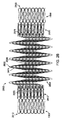
図33、図33A、および図34は、二重壁ステントシステム3300の実施形態を例示している。ステントシステム3300は、一方が他方の上に配置されて共通の軸線Laを有する全体的に円筒の本体を形成する2つのステント要素、すなわち外側ステント要素3302および内側ステント要素3304を備えている。外側ステント要素3302は、ステントシステム3300の外径を画定する外面を備え、内側ステント要素3304は、ステントシステム3300の内径と、内部を通る中心流路管腔3421を画定している。中心流路管腔3421は、内部を通る血流を保つために一貫した所定の拡張直径を有する。例えば、一貫した所定の拡張直径は、ステントシステムが埋め込まれる体の血管の通常の直径とほぼ同じとすることができる。内側ステント要素3304は、近位端部3330と遠位端部3332との間に延在する円筒型の管状体を有する。内側ステント要素3304は、当業者に周知の任意の適当なステント構造とすることができ、内部に配置される弁(不図示)を備えることができる。
33, 33A, and 34 illustrate an embodiment of a double
外側ステント要素3302は、複数の長手方向に延在するバンドまたはスパー3328を備えている。バンド3328は、共通の長手方向軸線Laに対して平行に内側ステント要素3304の近位端部3330から遠位端部3332まで延在する全体的に直線のストリップまたは支持板(plank)の材料である。より具体的には、長手方向に延在するバンド3328のそれぞれの近位端部は、内側ステント要素3304の近接した近位端部3330に連結され、長手方向に延在するバンド3328のそれぞれの遠位端部は、内側ステント要素104の近接した遠位端部3332に連結されている。バンド3328は、内側ステント要素3304の管状体の長さにほぼ等しい長さを有する。内側ステント要素3304は、外側ステント要素3302のバンド3328の内側の径方向の中心または内部に位置し、溶接によって、または外側ステント要素3302と内側ステント要素3304を連結するための任意の他の適切な方法によって外側ステント要素3302に取り付けられている。
外側ステント要素3302の長手方向に延在するバンド3328は、内側ステント要素3304の短縮動力学(foreshotening dynamics)によって展開または径方向に拡張される。より具体的には、内側ステント要素3304は、径方向の拡張時に内側ステント要素の長さを減少させる一定量の短縮または収縮が生じるように設計されている。したがって、ステントシステム3300の径方向の拡張時に、内側ステント要素3304が、その直径が拡張して長さが短縮し、これによりバンド3328が血管壁に向かって外向きに膨らむまたは湾曲する。内側ステント要素3304の短縮時にバンド3328の近位端部および遠位端部が互いに近づくため、外側ステント要素3302の展開されたバンド3328が、径方向外向きに湾曲して血管壁に接触し、ステントシステム3300の治療部位への固定を助ける。内側ステント要素3304は、中心流路管腔3421が拡張直径に達するように径方向に拡張するが、内側ステント要素3304の外面は、血管壁に殆どまたは全く接触せず、むしろ外側ステント要素3302内の径方向の中心に維持される。内側ステント要素3304は、中心流路管腔3421が、埋め込まれたステントシステム3300の近位および遠位の血管寸法と実質的に一致した直径となるように構成されている。
The
本発明の別の実施形態では、外側ステント要素が、血管壁に適合し、血管壁に対抗する力を与える可変の大きい外径をステントシステムに与えるように、二重壁ステントシステムは、複数のセグメント、すなわち個別部分またはゾーンを備えることができる。例えば、図35に示されている二重壁ステントシステム3500は、それぞれが複数の独立した長手方向に延在するバンドを備えた3つの別個のセグメント3541、3543、および3545を有する外側ステント要素3502を備えている。セグメント3541、3543、および3545は、3つの対応する別個の部分、すなわち近位部分3523、中間部分3525、および遠位部分3527を有する内側ステント要素3504に別個に取り付けられている。セグメント3541、3543、および3545の外面は、拡張時にセグメントによって異なってもよいステントシステム3500の外径を画定する。近位部分3523、中間部分3525、および遠位部分3527を有する内側ステント要素3504の円筒型の管状体は、ステントシステム3500の内径を提供する、内部を通る中心流路管腔(不図示)を画定している。内側ステント要素3504の各部分3523、3525、および3527は、拡張時に同じまたは異なる程度に短縮するように設計することができ、言い方を代えれば、ストラットの設計に基づいて他の部分よりも大きい、小さい、または等しい収縮率を有することができる。様々な実施形態では、外側ステント要素3502および内側ステント要素3504は、ステントシステム3500の所望の動作によって任意の数の対応するセグメントまたは部分を有することができる。
In another embodiment of the present invention, the double wall stent system provides a plurality of variable outer diameters to the stent system that conform to the vessel wall and provide a force against the vessel wall. It can comprise segments, i.e. individual parts or zones. For example, the double
外側ステント要素3502の各セグメント3541、3543、および3545は、内側ステント要素3504の対応する部分3523、3525、および3527のそれぞれの近位端部から遠位端部まで延在する全体的に直線のストリップまたは支持板の材料である複数の長手方向に延在するバンドまたはスパーを備えている。より具体的には、セグメント3541を構成する複数の独立した長手方向に延在するバンド3628Aは、内側ステント要素3504の近位部分3523の周りに径方向に配置されている。長手方向に延在するバンド3628Aのそれぞれの近位端部は、近位部分3523の近位端部に連結され、長手方向に延在するバンド3628Aのそれぞれの遠位端部は、近位部分3523の遠位端部に連結されている。同様に、セグメント3543を構成する複数の独立した長手方向に延在するバンド3628Bは、内側ステント要素3504の中間部分3525の周りに径方向に配置されている。長手方向に延在するバンド3628Bのそれぞれの近位端部は、中間部分3525の近位端部に連結され、長手方向に延在するバンド3628Bのそれぞれの遠位端部は、中間部分3525の遠位端部に連結されている。さらに、セグメント3545を構成する複数の長手方向に延在するバンド3628Cは、内側ステント要素3504の遠位部分3527の周りに径方向に配置されている。長手方向に延在するバンド3628Cのそれぞれの近位端部は、遠位部分3527の近位端部に連結され、長手方向に延在するバンド3628Cのそれぞれの遠位端部は、遠位部分3527の遠位端部に連結されている。
Each
図35および図36に例示されている実施形態では、内側ステント要素3504の中間部分3525は、拡張時に相対短縮が近位部分3523および遠位部分3527よりも小さいストラット設計を有する。部分3523、3525、および3527の間の短縮の程度の差により、外側ステント要素3502のセグメント3541、3543、および3545の拡張の高さの差がもたらされる。より具体的には、外側ステント要素3502のセグメント3541、3543、および3545は、内側ステント要素3504の対応する部分の短縮動力学によって展開または径方向に拡張される。内側ステント要素3504の近位部分3523および遠位部分3527が受ける短縮の相対量が大きいため、外側ステント要素3502のセグメント3541および3545は、対応する中間部分3525に連結されたセグメント3543よりも径方向外向きに拡張または湾曲する。様々な短縮比率を有するセグメントおよびステント部分の数は、セグメントの異なる拡張高さをカスタマイズして血管壁の薄い領域に最小の力を提供し、血管壁がより大きな力を維持できる部分には最大の対抗する力を提供できるように、標的埋め込み領域の意図する構造および寸法を得るために選択することができる。
In the embodiment illustrated in FIGS. 35 and 36, the
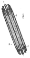
図1を参照すると、本発明の別の実施形態による二重壁ステントシステム100の斜視図が示されている。ステントシステム100は、2つのステント要素、すなわち外側ステント要素102および内側ステント要素104を備えている。内側ステント要素104は、互いに連結された複数のステントストラットを有する全体的に管状の円筒体を有し、外側ステント要素102の内側の中心または内部に位置している。外側ステント要素102および内側ステント要素104は、はんだ、溶接、または他の取付け手段によって互いに連結できる独立した分離要素として製造される。外側ステント要素102および内側ステント要素104は、径方向軸線および長手方向軸線を有する全体的に円筒の管状体を形成するために共通の長手方向軸線Laに対して整合している。
Referring to FIG. 1, a perspective view of a double
図2を参照すると、外側ステント要素102は、近位部分208および遠位部分218を有する。近位部分208は、全体的に円筒のステントストラット210を備え、遠位部分218は、全体的に円筒のステントストラット220を備えている。近位ステントストラット210および遠位ステントストラット220は、共通の長手方向軸線Laに対して整合し、直線バンド228などの複数の長手方向に延在するコネクタによって連結されている。長手方向軸線Laは、外側ステント要素102の近位端部212から遠位端部222まで円筒本体内に延在する。直線バンド228は、近位ステントストラット210と遠位ステントストラット220を連結するために、共通の長手方向軸線Laに対して平行に外側ステント要素102の近位部分208から遠位部分218まで延在する全体的に直線のストリップまたは支持板の材料である。図2に示されている実施形態では、直線バンド228はそれぞれ、ほぼ同じ幅を有する。
With reference to FIG. 2, the
本発明の別の実施形態では、第1の長手方向に延在するコネクタの幅は、第2の長手方向に延在するコネクタの幅と異なってもよい。例えば、図2Aは、複数の長手方向に延在するコネクタ228Aを含む外側ステント要素102Aの一部の拡大平面図を例示している。第1のバンド235は、幅W1を有し、第2のバンド237は、幅W2を有し、W1はW2よりも大きい。幅が異なる長手方向に延在するコネクタを形成することにより、血管壁内でのステントシステムの固定性を向上させ、幅が可変の長手方向に延在するコネクタを血管壁の拘束に一致させることができる。長手方向に延在するコネクタの表面積を変更することにより、より大きな設置面積に力が分散され、血管壁の損傷が少なくなり、固定性が向上する。例えば、装置の周囲に各種の幅の長手方向に延在するコネクタを備えた装置は、装置を特定の向きで血管内に配置する選択肢を提供する。これは、薄い血管壁の領域の損傷を最小限にするために装置を適切な向きで血管内に配置できるため、薄い血管壁と厚い血管壁の双方を有する血管に特に有利であろう。
In another embodiment of the invention, the width of the connector extending in the first longitudinal direction may be different from the width of the connector extending in the second longitudinal direction. For example, FIG. 2A illustrates an enlarged plan view of a portion of an
図2を再び参照すると、外側ステント要素102の近位部分208のステントストラット210は、近接する直線セグメント219を連結しているクラウン214と直線セグメント219のパターンを有する波状または正弦曲線円筒バンドまたはリングである。本願のために、クラウンが、波状または正弦曲線バンドの凹状ターンまたは曲線であることを理解されたい。ステントストラット210の直線セグメント219とクラウン214は、必ずしも端部で互いに連結する必要はなく、互いに続く、すなわち連続してもよい。一部の部分を、溶接、はんだ、接着剤、別の接着方法、または別の機械的な連結方法によって互いに機械的に連結することができるように、他の実施形態は、様々に形成することができる。しかし、ステントストラット210の特定の構造を説明するために、様々なセグメントおよびクラウンを、互いに連結または結合されているとして説明することができる。したがって、用語「と連結する」、「連結された」、または「結合された」は、互いに一体的に続く、すなわち連続しているか、または互いに機械的に結合されているかのいずれかを意味する。ステントストラット210と同様に、外側ステント要素102の遠位部分218のステントストラット220は、近接する直線セグメント229を連結しているクラウン224と直線セグメント229のパターンを有する波状または正弦曲線円筒バンドまたはリングである。一実施形態では、ステントストラット210、220は、それぞれ8つのクラウンを備えるが、当業者には、クラウンの数を変更してもよいことは明らかであろう。
Referring again to FIG. 2, the
上述したように、直線バンド228は、共通の長手方向軸線Laに対して平行に外側ステント要素102の近位端部212から遠位端部222まで延在する全体的に直線のストリップまたは支持板の材料である。より具体的には、長手方向に延在する直線バンド228のそれぞれの近位端部は、ステントストラット210のクラウン214の谷部216に連結され、直線バンド228のそれぞれの遠位端部は、ステントストラット220のクラウン224の反対の谷部226に連結されている。本願のために、谷部は、波状または正弦曲線バンドのクラウンによって形成された、開口した湾曲部分、すなわちくりぬかれた部分であることを理解されたい。長手方向に延在するコネクタは、近位ステントストラットの谷部から遠位ステントストラットの谷部まで延在するため、「谷部と谷部」のコネクタと呼ぶことができる。谷部と谷部のコネクタ、すなわち直線バンド228は、内側ステント要素104がステントストラット210と220との間の中心に位置できるように、ステントストラット210と220の長さに内側ステント要素104の長さを加えた長さにほぼ等しい長さを有する。一実施形態では、外側ステント要素102は、合計8つの長手方向に延在する直線バンド228を備えている。
As described above, the
本発明の別の実施形態では、長手方向に延在するコネクタは、共通の長手方向軸線Laに対して平行ではない。例えば、図2Bは、複数の長手方向に延在するコネクタ228Bを備えた外側ステント要素102Bの一部の拡大平面図を例示している。コネクタ228Bは、近位ステントストラット210Bと遠位ステントストラット220Bを連結するために、外側ステント要素102Bの近位部分208Bを遠位部分218Bに連結するストリップまたは支持板の材料である。コネクタ228Bは、共通の長手方向軸線Laに対して平行に延在するのではなく、共通の長手方向軸線Laに対して斜め、すなわち傾斜している。より具体的には、各コネクタ228Bの近位端部は、ステントストラット210Bの近接する谷部に離隔して連結されているが、各コネクタ228Bの遠位端部は、ステントストラット220Bの1つのクラウンに重なって連結されている。コネクタ228Bの傾斜すなわち角度は、拡張されたコネクタ228Bの安定を助け、これにより血管壁に追加の力を加えてステントシステムの治療部位への固定を助けることができる。
In another embodiment of the present invention, the connector extending in the longitudinal direction is not parallel to the common longitudinal axis L a. For example, FIG. 2B illustrates an enlarged plan view of a portion of the
ここで、図3を参照すると、内側ステント要素104は、共通の長手方向軸線La、近位端部330、および遠位端部332を有する円筒型の管状体である。長手方向軸線Laは、内側ステント要素104の近位端部330から遠位端部332まで円筒体内に延在する。複数の近接するステントストラット334は、内側ステント要素104の円筒型の管状体の形状を形成するために、長手方向軸線Laに対して実質的に平行に整合している。図3は、連結部342で連結された6つのステントストラット334を有する内側ステント要素104を示している。当業者であれば、内側ステント要素104が、ステントシステム100の所望の長さによってあらゆる数のステントストラット334を有することができることが解る。
Referring now to FIG. 3, the
各ステントストラット334は、近接する直線セグメント339を連結しているクラウン338と直線セグメント339のパターンを有する波状もしくは正弦曲線円筒バンドまたはリングである。本願のために、クラウンが、波状または正弦曲線バンドの凹状ターンまたは曲線であることを理解されたい。各波状または正弦曲線円筒バンドの直線セグメント339およびクラウン338は、端部で必ずしも互いに結合する必要はなく、互いに続く、すなわち連続してもよい。各ステントストラット334は、それぞれが直線セグメント339とクラウン338の実質的に同様のパターンを有するという点で機能的に同じである。近接するステントストラット334は、1つのストラットのクラウンが近接するステントストラット334の対応するクラウンと整合するように整合されている。近接するステントストラット334間の連結部342は、近接するステントストラット334のクラウンが整合している部分に形成されている。連結部342は、抵抗溶接、摩擦溶接、レーザー溶接、または別の形態の溶接などによって互いにターンを溶接することによって、追加の材料を用いずにステントストラット334を連結して形成するのが好ましい。あるいは、ステントストラット334は、はんだによって、ターンの間に連結要素を加えることによって、または別の機械的方法によって連結することができる。さらに、内側ステント要素104は、中空管またはシートから全ステント本体をレーザーカットまたはエッチングなどによって単一構造として予め連結して形成することができる。近接するストラットを結合するための他の連結または手段も、当業者には明らかであり、本明細書に含まれるものとする。内側ステント要素104は、当分野で周知の任意の適当なステントとすることができ、詳細を後に説明するように内部に配置される弁を備えることができる。
Each
図4は、連結部406で互いに結合されて二重壁ステントシステム100を形成している外側ステント要素102および内側ステント要素104を例示している。内側ステント要素104は、外側ステント要素102のストラット210と220との間の中心に位置している。外側ステント要素102と内側ステント要素104は、内側ステント要素104の近位端部および遠位端部の最外側クラウン338が、外側ステント要素102の近位端部210および遠位端部220の最内側クラウン214、224と整合するように整合されている。連結部406は、近接する最外側クラウンと最内側クラウンが整合する部分に形成されている。連結部406は、抵抗溶接、摩擦溶接、レーザー溶接、または別の形態の溶接などによって互いにターンを溶接することによって、追加の材料を用いずに外側ステント要素102と内側ステント要素104を連結して形成するのが好ましい。あるいは、外側ステント要素102と内側ステント要素104は、はんだによって、ターンの間に連結要素を加えることによって、または別の機械的方法によって連結することができる。図4に示されている実施形態では、内側ステント要素104は、6つのステントストラット334を備えており、内側ステント要素104を外側ステント要素102に連結または融合してステントシステム100を形成すると、ステントシステム100は、合計8つのステントストラットまたはセグメントを有する。
FIG. 4 illustrates an
図5〜図10を参照して説明する別の実施形態では、外側ステント要素102および内側ステント要素104は、これらの間にスナップフィット結合または締りばめ結合を含むように構成することができる。スナップフィット結合は、内側ステント要素のオス型要素を外側ステント要素の対応するメス型要素内に収容させる機械式インターロックである。スナップフィット結合のオス型要素とメス型要素は、圧入によって結合し、溶接、はんだ、または低温結合によって互いにさらに融合することができる。スナップフィット結合は、外側ステント要素と内側ステント要素の適切な整合を保証する。加えて、溶接されたスナップフィット結合は、ステントシステムの外径を増加させないため、ステントシステムの全寸法を最小にし、他の溶接構造に比べて応力を最小化または緩和する。
In another embodiment described with reference to FIGS. 5-10, the
図5を参照すると、外側ステント要素502は、その近位部分508および遠位部分518の両方にメス型収容部544を設けることによって対応する内側ステント要素に連結するように構成されている。メス型収容部544は、ステントストラット510、520の最内側クラウン514、524に位置している。図6に示されているように、内側ステント要素604は、その近位端部630および遠位端部632の両方にオス型タブ646を設けることによって外側ステント要素502に連結するように構成されている。オス型タブ646は、最近位ステントストラット634の最外側クラウン638および最遠位ステントストラット634の最外側クラウン638に位置している。オス型タブ646は、外側ステント要素502のメス型収容部644内に適合するように構成されている。図7は、スナップフィット結合部748によって互いに結合された外側ステント要素502および内側ステント要素604を備えたステントシステム700を例示している。内側ステント要素604は、外側ステント要素502のストラット510と520との間の中心に位置している。外側ステント要素502と内側ステント要素604を、内側ステント要素604のオス型タブ646が外側ステント要素502のメス型収容部544内に収容されるように整合されている。オス型タブ646を、メス型収容部544内に圧入し、スナップフィット結合部748を、さらに溶接、はんだ付け、または低温結合する。低温結合されたスナップフィット結合部748は、例えば、CoCr合金、ステンレス鋼、およびMP35N合金などの異種金属へのNiTi(ニチノール)の溶接または融合における冶金作用(metallurgical effect)および技術的問題点を解消する。加えて、低温結合されたスナップフィット結合部748には、ステントシステムの要素に存在するブタの弁や同種材料などの組織、ポリマー剤、または薬剤から形成された要素に影響を与えうる溶接および溶接による熱誘導の回避などのいくつかの製造上の利点が存在する。
Referring to FIG. 5, the
図8は、内側ステント要素604のステントストラット634と外側ステント要素502のステントストラット520との間のスナップフィット結合部748の拡大平面図を例示している。各スナップフィット結合部748は、内側ステント要素の最遠位ステントストラット634の最外側クラウン638から延びたオス型要素(オス型タブ646)およびステントストラット520の最内側クラウン524の中に延びたメス型要素(メス型収容部544)を含む機械式インターロックである。したがって、各オス型要素は、対応するメス型要素内に収容される。図8に示されている実施形態では、オス型タブ646は、上側平面および下側平面と、メス型収容部544が対応する実質的に円形の凹部である実質的に丸い外周部を有する。ストラット部分が取り付けられたスナップフィット結合部748のオス型要素およびメス型要素は、別個に形成され、組立てが必要である。スナップフィット結合部748のオス型要素とメス型要素は、圧入によって結合することができ、溶接、はんだ付け、または低温結合によって、さらに互いに融合することができる。スナップフィット結合部は、外側ステント要素と内側ステント要素の適切な整合を保証し、他の溶接構造と比べて応力を最小化または緩和する。オス型要素(オス型タブ646)が内側ステント要素604に配置され、メス型要素(メス型収容部544)が外側ステント要素502に配置されたスナップフィット結合部748が例示されているが、当業者であれば、オス型要素を外側ステント要素に配置し、メス型要素を内側ステント要素に配置できることが解る。
FIG. 8 illustrates an enlarged plan view of a snap fit joint 748 between the
図9は、内側ステント要素604と外側ステント要素902との間のスナップフィット結合部の代替実施形態の拡大平面図である。図8を参照して上記説明した実施形態と同様に、オス型要素(オス型タブ646)が、内側ステント要素の最遠位ステントストラット634の最外側クラウン638から延びている。しかし、この実施形態では、メス型要素は、外側ステント要素の中の凹部ではなく、オス型タブ646を収容するために一致した凹部形状を有する取付けメス型収容部(attached female receptacle)950である。メス型収容部950は、ステントストラット920の最内側クラウン924から延びている。メス型収容部950は、「端部開口」収容部として例示されている。別の実施形態(不図示)では、メス型要素は、完全なリングの形態の閉じた収容部である。閉じた完全なリングは、円形、卵形、または楕円形とすることができる。
FIG. 9 is an enlarged plan view of an alternative embodiment of a snap fit joint between the
図10は、内側ステント要素1004と外側ステント要素1002との間の代替締りばめ結合部の拡大平面図を例示している。この実施形態では、締りばめ結合部は、内側ステント要素の最遠位ステントストラット1034の最外側クラウン1038から延びたオス型要素(オス型タブ1046)およびステントストラット1020の最内側クラウン1024の中に延びたメス型要素(メス型収容部1044)を含む。オス型要素とメス型要素が、スナップフィット結合部のように「スナップ式」に所定の位置に収まるのではなく、オス型タブ1046を、メス型収容部1044内にスライドさせるかまたは収容して、溶接または他の方法で恒久的にメス型収容部1044に固定する。締りばめ結合部は、外側ステント要素と内側ステント要素との整合を保証し、他の溶接構造と比べて応力を最小化または緩和する。
FIG. 10 illustrates an enlarged plan view of an alternative interference fit joint between the
二重壁ステントシステム100は、治療部位に送達するのに十分な収縮または圧縮された幾何学的配置1152(図11および図12を参照)および拡張または展開された幾何学的配置1354(図13および図14を参照)を有する。図11は、収縮または圧縮された幾何学的配置1152のステントシステム100の側面図を示し、図12は、収縮または圧縮された幾何学的配置1152のステントシステム100の端面図を例示している。外側ステント要素102は、体の管腔内に送達するのに十分な直径D1にステントシステム100を圧縮するために内側ステント要素104に対してクリンプされている。収縮または圧縮された幾何学的配置1152では、ステントシステム100は、長さL1を有する。
Double
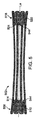
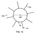
ここで、図13および図14を参照すると、図13は、拡張または展開された幾何学的配置1354のステントシステム100の側面図を示し、図14は、拡張または展開された幾何学的配置1354のステントシステム100の端面図を例示している。外側ステント要素102の長手方向に延在する直線バンド228は、内側ステント要素104の短縮動力学によって展開または径方向に拡張される。より具体的には、内側ステント要素104は、径方向の拡張時に内側ステント要素の長さを短縮する一定程度の短縮性を有するように設計されている。内側ステント要素104の直径が拡張して長さが減少すると、外側ステント要素102の長手方向に延在するコネクタが、血管壁に向かって外向きに膨らむ。拡張または展開された幾何学的配置1354では、ステントシステム100は、長さL1よりも短い長さL2を有する。別の言い方をすれば、ステントシステム100が径方向に拡張すると、ステントシステム100の長さが減少する。直線バンド228の近位端部および遠位端部が、内側ステント要素104の短縮時に互いに近づくため、外側ステント要素102の展開された直線バンド228が、径方向外向きに湾曲して血管壁に接触し、ステントシステム100の治療部位への固定を助ける。内側ステント要素104は、直径D1よりも大きい直径D2まで径方向に拡張して、内部を通る中心流路管腔1421を形成する。中心流路管腔3421は、内部を通る血流を保つために一貫した所定の拡張直径を有する。例えば、一貫した所定の拡張直径は、ステントシステムが埋め込まれる体の血管の通常の直径とほぼ同じにすることができる。一実施形態では、拡張または展開された幾何学的配置1354では、中心流路管腔1421の直径は約18mmである。しかし、内側ステント要素104の外面は、図13および図14に示されているように、血管壁に殆どまたは全く接触せず、むしろ外側ステント要素102内の径方向の中心に維持される。内側ステント要素104は、体の管腔の径方向の中心または管腔内に位置するように構成されている。
Referring now to FIGS. 13 and 14, FIG. 13 shows a side view of the
内側ステント要素104は、いくつかの方法で拡張させることができる。一実施形態では、自己拡張型ステントの展開は、ニッケル‐チタン(ニチノール)などの材料の形状記憶特性を利用することによって容易にすることができる。形状記憶合金は、一定の熱または応力条件に曝露されると規定の形状またはサイズに戻る能力を有する金属組成物群である。形状記憶金属は、一般に、比較的低い温度で変形し、比較的高い温度に曝露されると、形状記憶合金が変形前に維持していた規定の形状またはサイズに戻ることができる。このため、ステントは、変形した小さい状態で体に挿入され、in vivoで高温、すなわち体温または加熱流体に曝露されると「記憶した」大きい形状に戻ることができる。したがって、自己拡張ステントは、サイズまたは形状の2つの状態、すなわち治療部位に送達するのに十分な収縮または圧縮された幾何学的配置および血管壁に接触するための展開すなわち拡張された幾何学的配置を有することができる。内側ステント要素は、ニッケル‐チタン(ニチノール)などの熱膨張材料から形成することができる。治療部位すなわち展開部位に配置されると、ステントシステムが熱源に曝露され、ステントシステムの内側ステント要素が、ステント要素を形成する材料によって化学反応または熱膨張によって拡張する。内側ステント要素の管状体は、その熱成形型に開いて短縮寸法になるため、外側ステント要素の長手方向に延在するコネクタが拡張して外側に向かって湾曲し、血管壁に接触し、血管に必要な対抗する力を与える。
The
別の実施形態では、内側ステント要素は、自己拡張ばね型材料またはニッケル‐チタン(ニチノール)などの超弾性材料から形成することができ、血管内に送達するために送達カテーテルに対して拡張した形状から収縮または圧縮された幾何学的配置に折り畳むまたはクリンプすることができる。ステントシステムを折り畳まれた状態に保持するスリーブまたはシースが除去されると、内側ステント要素は、血管内の治療部位で拡張または展開された状態をとる。内側ステント要素の拡張および短縮により、外側ステント要素の長手方向に延在するコネクタが外側に向かって湾曲し、血管壁に接触する。 In another embodiment, the inner stent element can be formed from a self-expanding spring-type material or a superelastic material such as nickel-titanium (Nitinol) and has an expanded shape relative to the delivery catheter for delivery into the blood vessel. Can be folded or crimped into a contracted or compressed geometry. When the sleeve or sheath that holds the stent system in the collapsed state is removed, the inner stent element assumes the expanded or deployed state at the treatment site within the vessel. Due to the expansion and contraction of the inner stent element, the longitudinally extending connector of the outer stent element bends outward and contacts the vessel wall.
別の実施形態では、内側ステント要素は、治療部位への送達のためにバルーン拡張カテーテルに対してクリンプし、バルーンの径方向の力によって拡張されるようにバルーン拡張型とすることができる。より具体的には、ステントシステムは、血管形成術に用いられるタイプのバルーンなどのバルーンの上部に対して収縮または圧縮した幾何学的配置に折り畳むことができる。バルーンは、膨張すると、内側ステント要素を物理的に押圧して径方向に拡張させる。内側ステント要素の拡張および短縮により、外側ステント要素の長手方向に延在するコネクタが外側に向かって湾曲し、血管壁に接触する。次いで、バルーンが収縮され、ステントシステムは、拡張または展開された幾何学的配置のままである。例えば、図15は、本発明の実施形態によるステント送達システム1501の例示である。ステント送達システム1501は、近位シャフト1505、ガイドワイヤシャフト1515、およびバルーン1507を有するオーバーザワイヤカテーテル1503を備えている。近位シャフト1505は、ハブ1509に取り付けられた近位端部およびバルーン1507の近位端部に取り付けられた遠位端部を有する。ガイドワイヤシャフト1515は、ハブ1509から近位シャフト1505およびバルーン1507を通ってカテーテル1503の遠位先端部まで延びている。ハブ1509は、膨張用流体の供給源に取り付けるための膨張用ポート1511を備えている。膨張用ポート1511は、近位シャフト1505内に延びた膨張用管腔(不図示)を介してバルーン1507に流体的に連通している。加えて、ハブ1509は、内部を通るガイドワイヤ1517を収容するためのガイドワイヤシャフト1515によって画定されたガイドワイヤ管腔(不図示)に連通したガイドワイヤポート1513を備えている。本明細書に記載するように、ガイドワイヤシャフト1515は、オーバーザワイヤ構造のカテーテル1503の全長に渡って延在する。しかし、当業者には理解できるように、ガイドワイヤシャフト1515は、代わりに、迅速交換構造のカテーテル1503の遠位部分内にのみに延在するようにしてもよい。本発明の実施形態に基づいて形成された二重壁ステントシステム100は、バルーン1507の上に配置される。しかし、当業者であれば、本発明のステントシステムを、あらゆる種類の送達および拡張方法に適応させることができることが解る。加えて、当業者であれば、一方のステント要素を自己拡張型とし、他方のステント要素をバルーン拡張型とすることができることが解る。
In another embodiment, the inner stent element can be balloon expandable so that it is crimped against a balloon dilatation catheter for delivery to the treatment site and is expanded by the radial force of the balloon. More specifically, the stent system can be folded into a contracted or compressed geometry relative to the top of a balloon, such as the type of balloon used in angioplasty. When the balloon is inflated, it physically presses the inner stent element to radially expand it. Due to the expansion and contraction of the inner stent element, the longitudinally extending connector of the outer stent element bends outward and contacts the vessel wall. The balloon is then deflated and the stent system remains in the expanded or deployed geometry. For example, FIG. 15 is an illustration of a
すべての実施形態では、二重壁ステントシステムの外側ステント要素および内側ステント要素は、良好な機械強度を有する埋め込み用材料から形成されるのが好ましい。例えば、両方の要素は、ステンレス鋼、コバルト系合金(605L、MP35N)、チタン、タンタル、プラチナ合金、ニオブ合金、超弾性ニッケル‐チタン合金(ニチノール)、他の生体適合性金属、またはポリマーなどの他の材料から形成することができる。ステントに広く使用されている1つの材料は、ステンレス鋼、特に、非常に腐食耐性に優れている316Lステンレス鋼である。必ずしも必要ではないが、1つまたは複数のステント要素を、蛍光透視中の視認性を改善するためにプラチナまたは他の生体適合性材料で選択的にめっきすることができる。加えて、外側ステント要素および/または内側ステント要素は、ポリエステルまたはDacron繊維で選択的に覆うことができる。 In all embodiments, the outer and inner stent elements of the double wall stent system are preferably formed from an implantable material having good mechanical strength. For example, both elements include stainless steel, cobalt-based alloys (605L, MP35N), titanium, tantalum, platinum alloys, niobium alloys, superelastic nickel-titanium alloys (Nitinol), other biocompatible metals, or polymers, etc. It can be formed from other materials. One material that is widely used for stents is stainless steel, particularly 316L stainless steel, which is highly corrosion resistant. Although not necessary, one or more stent elements can be selectively plated with platinum or other biocompatible material to improve visibility during fluoroscopy. In addition, the outer stent element and / or the inner stent element can be selectively covered with polyester or Dacron fibers.
いくつかの従来のレーザーカット法のいずれかを用いて、中実材または管材から外側ステント要素および内側ステント要素を所望の形状またはパターンに形成することができる。例えば、図16は、図6の内側ステント要素604のレーザーカット部分要素1656を例示している。内側ステント要素604は、外径が約0.25インチ、肉厚が約0.012インチのMP35N管材または任意の他の適当な管材からレーザーカットすることができる。レーザーカット部分要素1656は、全体的に円形の内側ステント要素604がカットされて平坦に広げられたように略図に示されている。全体的に円筒のステントストラット634は、平坦な状態で示されているが、当業者であれば、図面に描かれているステントストラット634が円筒本体に使用されることが意図されていることが解る。シート材または管材からレーザーカットする場合、内側ステント要素604のステントストラット634は、要素本体が単一構造となるように互いに連結して形成することができる。図示されているように、オス型タブ646も、要素が単一構造となるように内側ステント要素604の近位端部および遠位端部に連結されて形成されている。
Any of several conventional laser cutting methods can be used to form the outer and inner stent elements into a desired shape or pattern from solid or tubing. For example, FIG. 16 illustrates a
図17は、図5の外側ステント要素502のレーザーカット部分要素1758を例示している。外側ステント要素502は、外径が約0.25インチ、肉厚が約0.012インチのMP35N管材または任意の他の適当な管材からレーザーカットすることができる。レーザーカット部分要素1758は、全体的に円形の外側ステント要素502がカットされて平坦に広げられたように略図に示されている。全体的に円筒のステントストラット510、520は、平坦な状態で示されているが、当業者であれば、図面に描かれているステントストラット510、520が円筒本体に使用されることが意図されていることが解る。シート材または管材からレーザーカットする場合、外側ステント要素502のステントストラット510、520および長手方向に延在する直線バンド528は、要素本体が単一構造となるように互いに連結して形成することができる。図示されているように、メス型収容部544も、要素が単一構造となるように外側ステント要素502の近位部分および遠位部分に形成されている。
FIG. 17 illustrates a
加えて、任意の適当な管材からレーザーカットするのではなく、二重壁ステントシステムの外側ステント要素および内側ステント要素は、当業者に明らかな任意の他の方法で製造することができる。例えば、ステントストラットは、ワイヤまたはリボンをマンドレルに巻き付けて上記のパターンを形成し、次いでその両端部を溶接または他の方法で機械的に連結することによって形成することができる。次いで、ステントストラットを、互いに連結して内側ステント要素を形成するか、または長手方向に延在するコネクタに連結して外側ステント要素を形成する。あるいは、ステントストラットは、管材または中実材を環状バンドに機械加工し、次いでこのバンドをマンドレルに対して曲げて所望のパターンを形成することによって製造することができる。このように形成されたステントストラットも、次に互いに連結して内側ステント要素を形成するか、または長手方向に延在するコネクタに連結して外側ステント要素を形成する。完成したステントシステムの断面形状は、円形、楕円形、長方形、六角形、正方形、または他の多角形にすることができるが、現在は、円形または楕円形が好ましいであろうと考えられている。 In addition, rather than laser cutting from any suitable tubing, the outer and inner stent elements of the double wall stent system can be manufactured in any other manner apparent to those skilled in the art. For example, a stent strut can be formed by wrapping a wire or ribbon around a mandrel to form the pattern described above, and then welding or otherwise mechanically connecting its ends. The stent struts are then joined together to form an inner stent element, or are connected to a longitudinally extending connector to form an outer stent element. Alternatively, stent struts can be manufactured by machining tube or solid material into an annular band and then bending the band relative to the mandrel to form the desired pattern. The stent struts thus formed are then connected together to form an inner stent element or connected to a longitudinally extending connector to form an outer stent element. The cross-sectional shape of the completed stent system can be circular, elliptical, rectangular, hexagonal, square, or other polygonal shape, but it is now believed that circular or elliptical shape would be preferred.
外側ステント要素および内側ステント要素が上記した1つの方法で別個に形成されたら、二重壁ステントシステムを形成するためにこれらの要素を互いに結合する。これらの要素は、溶接、はんだ、低温結合、または他の方法で機械的に互いに連結することができる。本発明の実施形態による製造方法では、これらの要素は、内側ステント要素を内部に挿入できる十分なサイズまで外側ステント要素を拡張させて互いに連結する。次いで、外側ステント要素を、内側ステント要素に対してクリンプまたは圧縮して収縮または圧縮された幾何学的配置にする。内側ステント要素と外側ステント要素との間の近接するクラウンを、溶接、はんだ、低温結合、または他の方法で機械的に互いに連結する。 Once the outer and inner stent elements have been formed separately in one of the ways described above, these elements are joined together to form a double wall stent system. These elements can be mechanically connected to each other by welding, soldering, cold bonding, or other methods. In a manufacturing method according to an embodiment of the present invention, these elements connect the outer stent elements by expanding them to a size sufficient to allow the inner stent elements to be inserted therein. The outer stent element is then crimped or compressed against the inner stent element into a contracted or compressed geometry. Adjacent crowns between the inner and outer stent elements are mechanically connected to each other by welding, soldering, cold bonding, or other methods.
上記説明したように、これらの要素は、ステントシステムに組み立てられるとスナップフィット結合または締りばめ結合を形成する、対応するオス型要素およびメス型要素を備えることができる。スナップフィット結合または締りばめ結合のオス型要素およびメス型要素が存在する場合は、これらの要素は、内側ステント要素を内部に挿入できる十分なサイズまで外側ステント要素を拡張させて互いに連結する。内側ステント要素が外側ステント要素に挿入されたら、オス型要素をメス型要素内に整合させる。したがって、スナップフィット結合または締りばめ結合は、外側ステント要素と内側ステント要素の適切な整合を保証する。次いで、外側ステント要素を、内側ステント要素に対してクリンプまたは圧縮して収縮または圧縮された幾何学的配置にする。次いで、オス型要素をメス型要素内に圧入する。次いで、オス型要素およびメス型要素のスナップフィット結合または締りばめ結合を、溶接、はんだ、低温結合、または他の方法で機械的に互いに連結する。 As described above, these elements can include corresponding male and female elements that form a snap-fit or interference fit connection when assembled to a stent system. When there are snap fit or interference fit male and female elements, these elements expand the outer stent elements to connect to each other to a size sufficient to allow the inner stent elements to be inserted therein. Once the inner stent element is inserted into the outer stent element, the male element is aligned within the female element. Thus, a snap fit connection or an interference fit connection ensures proper alignment of the outer and inner stent elements. The outer stent element is then crimped or compressed against the inner stent element into a contracted or compressed geometry. The male element is then press fit into the female element. The snap-fit or interference fit connection of the male and female elements is then mechanically coupled together by welding, soldering, cold bonding, or other methods.
低温結合されたスナップフィット結合部は、例えば、CoCr合金、ステンレス鋼、およびMP35N合金などの異種金属へのNiTi(ニチノール)の溶接または融合における冶金作用および技術的問題点を解消する。例えば、メス型要素を、NiTi(ニチノール)から形成することができ、オス型要素を、上に列記した1つのような異種金属から形成することができる。オス型要素およびメス型要素の低温結合連結部は、室温(オーステナイト相)で最終的に「展開された」結合寸法に形成することによって開始する。所望の結合効果を生成するために、メス型要素の温度を、その遷移温度(TT)よりも十分に低くして、マルテンサイト相に変態させる。実際には、これは、要素を液体窒素槽に浸漬することによって達成することができる。この状態で、メス型要素の孔または凹部の中にオーバーサイズのテーパマンドレルを長手方向に押し込むことによって、メス型要素の孔または凹部を径方向に拡張または拡大する。遷移温度よりも低く継続的に冷却すると、メス型要素は、安定した拡張を維持する。次いで、メス型要素とオス型要素の結合を、オス型要素の端部を拡張したメス型要素の中に挿入して、メス型要素を加温してほぼ元の直径、すなわち記憶直径にすることによって達成する。メス型要素の径方向の収縮および関連した慢性の力が、体温、すなわち37℃よりも十分に低く設計された遷移温度よりも高い温度で連続的にクランプする接合部を可能にする。メス型要素が、図8〜図10に示されている実施形態のような「端部開口」収容部を有する場合、楔効果により、オス型要素が、メス型要素の外径からメス型要素の内径への径方向の通過が防止される。別の実施形態では、メス型要素は、完全なリングの形態の閉じた収容部である。このリングは、円形、卵型、または楕円形とすることができる。オス型要素は、メス型要素の閉じた収容部を通過すると、径方向、軸方向、またはこれらが組み合わせられた方向に締め付けられる。 Low temperature bonded snap fit joints eliminate metallurgical effects and technical problems in welding or fusing NiTi (Nitinol) to dissimilar metals such as, for example, CoCr alloys, stainless steel, and MP35N alloys. For example, the female element can be formed from NiTi (Nitinol) and the male element can be formed from dissimilar metals such as one listed above. The cold bond joint of the male and female elements begins by forming a final “developed” bond dimension at room temperature (austenite phase). In order to produce the desired bonding effect, the temperature of the female element is made sufficiently lower than its transition temperature (TT) to transform into a martensitic phase. In practice, this can be achieved by immersing the element in a liquid nitrogen bath. In this state, the hole or recess of the female element is expanded or enlarged in the radial direction by pushing the oversized taper mandrel longitudinally into the hole or recess of the female element. When continuously cooled below the transition temperature, the female element maintains stable expansion. Then, the coupling of the female element and the male element is inserted into the female element with the end of the male element expanded, and the female element is heated to approximately its original diameter, that is, the memory diameter. To achieve. The radial contraction of the female element and the associated chronic force allows the joint to continuously clamp at body temperature, ie a temperature higher than the designed transition temperature well below 37 ° C. When the female element has an “end opening” housing as in the embodiment shown in FIGS. 8-10, the wedge effect causes the male element to move from the outer diameter of the female element to the female element. Passing in the radial direction to the inner diameter of the is prevented. In another embodiment, the female element is a closed receptacle in the form of a complete ring. The ring can be circular, oval or elliptical. As the male element passes through the closed receptacle of the female element, it is clamped in the radial direction, axial direction, or a combination thereof.
上記したように、本発明の一部の実施形態では、外側ステント要素は、長手方向に延在するコネクタによって互いに連結された近位ステントストラットおよび遠位ステントストラットを備えている。別の実施形態では、ステントの移動および弁の漏れを防止するために、フレアステントストラットを外側ステント要素の近位端部および遠位端部に取り付けることができる。より具体的には、図18Aおよび図18Bを参照して、「直線」二重壁ステントシステムを通る流れを、「フレア」二重壁ステントシステムを通る流れと比較する。内側ステント要素は、管状セグメント1864によって表され、外側ステント要素は、細長い長円形セグメント1865によって表されている。図18Aは、直線端部を有する管状セグメント1864を通る、矢印1860によって表される流れを例示している。流れ1860は、システム内に主に真直に案内される。しかし、管状セグメント1864の比較的小さいインレットにより、矢印1862によって表される流れの一部が、入口に「入りそこない」、システムの近位端部のセグメント1865の側面で跳ね返され反転する。同様に、管状セグメント1864の比較的小さい出口により、矢印1863によって表される流れの一部が逆流して、システムの遠位端部のセグメント1865の側面で跳ね返され、反転する。流れ1862は、システムの不所望の回転移動、およびシステムを遠位側に予測不可能な距離移動させる「ウォーターメロンシーディング(watermelon seeding)」として知られる現象をもたらす。
As described above, in some embodiments of the present invention, the outer stent element comprises a proximal stent strut and a distal stent strut connected to each other by a longitudinally extending connector. In another embodiment, flare stent struts can be attached to the proximal and distal ends of the outer stent element to prevent stent migration and valve leakage. More specifically, with reference to FIGS. 18A and 18B, the flow through a “straight” double wall stent system is compared to the flow through a “flared” double wall stent system. The inner stent element is represented by a
相対的に、フレア端部セグメントは、このような不所望の移動を防止するのに役立ち、うっ血およびこれに続く血栓形成作用を防止するために適切な長さおよびフレア角で形成することができる。図18Bは、フレア端部1866を有する管状セグメント1864を通る、矢印1860によって表される流れを例示している。フレア入口端部1866の比較的大きい入口により、流れ1860は、システムの近位端部でシステム内に真直に案内される。同様に、フレア出口端部1867の比較的大きい出口により、流れ1860は、システムの遠位端部でシステム外に真直に案内される。
In comparison, the flare end segment helps prevent such undesired movement and can be formed with an appropriate length and flare angle to prevent congestion and subsequent thrombus formation. . FIG. 18B illustrates the flow represented by
図19は、近位端部および遠位端部にフレアステントストラット1968を有する外側ステント要素1902の側面図を示している。外側ステント要素1902は、近位部分1908および遠位部分1918を有する。外側ステント要素102と同様に、近位部分1908は、全体的に円筒のステントストラット1910を備え、遠位部分1918は、全体的に円筒のステントストラット1920を備えている。外側ステント要素1902の近位部分1908におけるステントストラット1910は、近接する直線セグメント1919を連結しているクラウン1914と直線セグメント1919のパターンを有する波状もしくは正弦曲線円筒バンドまたはリングであり、外側ステント要素1902の遠位部分1918におけるステントストラット1920は、近接する直線セグメント1929を連結しているクラウン1924と直線セグメント1929のパターンを有する波状もしくは正弦曲線円筒バンドまたはリングである。近位ステントストラット1910および遠位ステントストラット1920は、共通の長手方向軸線Laに対して整合し、直線バンド1928などの複数の長手方向に延在するコネクタによって連結されている。直線バンド1928は、共通の長手方向軸線Laに対して平行にステントストラット1910のクラウン1914の谷部1916からステントストラット1920のクラウン1924の反対側の谷部1926まで延在する全体的に直線のストリップまたは支持板の材料である。しかし、外側ステント要素102とは異なり、図19に例示されている実施形態は、外側ステント要素1902の近位端部1912および遠位端部1922にフレアステントストラット1968を備えている。フレアステントストラット1968は、近位端部1912および遠位端部1922が長手方向軸線Laに対して約20度の角度を成すように近位ステントストラット1910および遠位ステントストラット1920に連結されて径方向にフレアである。したがって、近位端部1912および遠位端部1922におけるフレアステントストラット1968の外径は、近位ステントストラット1910および遠位ステントストラット1920の外径よりも大きい。加えて、フレアステントストラット1968の直線セグメントは、近位ステントストラット1910および遠位ステントストラット1920の直線セグメント1919、1929よりも長くすることができ、フレアステントストラット1968のクラウンは、近位ステントストラット1910および遠位ステントストラット1920のクラウン1914、1924のそれぞれよりも大きくすることができる。フレアステントストラット1968は、不所望のステントの回転移動およびウォーターメロンシーディングを防止し、さらにうっ血およびこれに続く血栓形成作用を防止することができる。加えて、図19は、近位ステントストラット1910の最内側クラウン1914および遠位ステントストラット1920の最内側クラウン1924の両方に取付けメス型収容部1950を配置することによって内側ステント要素に連結されるように構成された外側ステント要素1902を示している。
FIG. 19 shows a side view of an
端部にフレアステントストラット1968が設けられた外側ステント要素1902を利用する二重壁ステントシステムは、ステントシステムが合計8つのステントストラットを保持するように、4つのステントストラットを有する内側ステント要素と共に用いることができる。例えば、図20は、フレア端部を有する外側ステント要素と共に用いることができる内側ステント要素2004を例示している。内側ステント要素2004は、長手方向軸線La、近位端部2030、および遠位端部2032を有する円筒型管状体である。長手方向軸線Laは、内側ステント要素2004の近位端部2030から遠位端部2032まで円筒体内に延在する。複数の近接するステントストラット2034は、内側ステント要素2004の円筒型管状体を形成するように長手方向軸線Laに対して実質的に平行に整合されている。各ステントストラット2034は、近接する直線セグメント2039を連結しているクラウン2038と直線セグメント2039のパターンを有する波状または正弦曲線円筒バンドまたはリングである。図20は、連結部2042で連結された4つのステントストラット2034を有する内側ステント要素2004を示している。加えて、図20は、内側ステント要素2004の近位端部2030および遠位端部2032の両方にオス型タブ2046を配置することによって外側ステント要素に連結するように構成された内側ステント要素2004を示している。
A double wall stent system utilizing an
本発明のさらなる実施形態では、外側ステント要素の近位部分を外側ステント要素の遠位部分に連結する長手方向に延在するコネクタは、いくつかの可能な実施形態を有する。既に説明したように、外側ステント要素の長手方向に延在するコネクタは、ステントシステムを治療部位に固定するのを助けるために展開されると血管壁に接触する。内側ステント要素が、体の管腔内の径方向の中心に維持されるため、そして外側ステント要素の長手方向に延在するコネクタが、潜在的な患者の成長および/または血管の異常にもかかわらず、システムが血管壁に対して固定されることを保証するために径方向外向きに湾曲するため、二重壁ステントシステムは、右心室流出路の異常の治療に特に適している。外側ステント要素の実施形態に関連して既に上記したように、長手方向に延在するコネクタは、外側ステント要素の近位端部から遠位端部まで延在する全体的に直線のバンド材料とすることができる。詳細を後述する本発明のさらなる実施形態では、外側ステント要素の長手方向に延在するコネクタは、長手方向および径方向の折り畳み可能な複数の波状もしくは正弦曲線バンドまたはスパーである。近接する長手方向に延在するコネクタの正弦曲線バンドまたはスパーは、互いに入れ子状にすることができる。長手方向に延在するコネクタは、外側ステント要素の長手方向軸線に対して概ね平行に延在しても、外側ステント要素の長手方向軸線に対して傾斜、すなわち角度を成して延在しても、または外側ステント要素の長手方向軸線の周りに螺旋状に延在してもよい。 In a further embodiment of the invention, the longitudinally extending connector connecting the proximal portion of the outer stent element to the distal portion of the outer stent element has several possible embodiments. As previously described, the longitudinally extending connector of the outer stent element contacts the vessel wall when deployed to help secure the stent system at the treatment site. Because the inner stent element is maintained at the radial center within the body lumen, and the longitudinally extending connector of the outer stent element is responsible for potential patient growth and / or vascular abnormalities. First, the double wall stent system is particularly suitable for the treatment of right ventricular outflow tract abnormalities because it is curved radially outward to ensure that the system is secured to the vessel wall. As already described above in connection with the embodiment of the outer stent element, the longitudinally extending connector comprises a generally straight band material extending from the proximal end to the distal end of the outer stent element. can do. In a further embodiment of the invention described in detail below, the longitudinally extending connector of the outer stent element is a plurality of longitudinal and radial foldable wavy or sinusoidal bands or spars. Adjacent longitudinally extending connector sinusoidal bands or spars can be nested together. The longitudinally extending connector extends generally parallel to the longitudinal axis of the outer stent element, but extends at an angle, i.e., at an angle, to the longitudinal axis of the outer stent element. Or it may extend helically around the longitudinal axis of the outer stent element.
例えば、図21は、本発明の別の実施形態による長手方向に延在するコネクタを備えた外側ステント要素2102の側面図を示している。この実施形態では、長手方向に延在するコネクタは、コネクタバンド2170である。コネクタバンド2170は、直線近位部分2172、波状または正弦曲線中間部分2174、および直線遠位部分2176を備えている。波状または正弦曲線中間部分2174は、ステントシステムの血管壁への固定をさらに助ける組織の成長を可能にし、かつ展開後のステントの移動を防止する追加の表面積およびポケットの両方を提供する。コネクタバンド2170は、共通の長手方向軸線Laに対して概ね平行にステントストラット2110のクラウン2114の谷部2116からステントストラット2120のクラウン2124の反対側の谷部2126まで延在する。直線近位部分2172および直線遠位部分2176は、ステントストラット2110、2120の直線セグメントの長さにほぼ等しい長さを有するが、正弦曲線中間部分2174は、組み立てられると内側ステント要素の全長に渡って全体的に延在するように、内側ステント要素の長さにほぼ等しい長さを有する。図21に示されている実施形態は、外側ステント要素2102の近位端部2112および遠位端部2122にフレアステントセグメント1968を備えているが、コネクタバンド2170は、本明細書に開示する外側ステント要素のいずれの実施形態でも長手方向に延在するコネクタとして用いることができることを理解されたい。
For example, FIG. 21 shows a side view of an
図22は、拡張または展開された幾何学的配置の二重壁ステントシステム2200の側面図を示し、図23は、拡張または展開された幾何学的配置のステントシステム2200の端面図を例示している。ステントシステム2200は、外側ステント要素2102(図21の)およびこの外側ステント要素2102に連結された内側ステント要素2004(図20の)を備えている。外側ステント要素2102は、ステントシステムの治療部位への固定を助けるために展開された波状コネクタバンド2170を備えている。中心流路管腔2321を画定している内側ステント要素2004は、外側ステント要素2102内の径方向の中心に拡張または展開された幾何学的配置で示されている。図22および図23に示されている実施形態は、4つのステントストラットを有する内側ステント要素を備えているが、この内側ステント要素は、システムの所望の全長および/または所望の機械特性によって任意の数のステントストラットを備えることができることを理解されたい。
FIG. 22 shows a side view of an expanded or deployed geometry double
図22および図23では、既に説明した他の実施形態と同様に、長手方向に延在するコネクタは、谷部と谷部のコネクタ、すなわち近位ステントストラットの谷部から遠位ステントストラットの谷部まで延在するコネクタである。しかし、長手方向に延在するコネクタは、近位ステントストラットのクラウンから遠位ステントストラットのクラウンまで延在する「クラウンとクラウン」のコネクタとしてもよい。例えば、図24は、本発明の別の実施形態による展開すなわち拡張された幾何学的配置の二重壁ステントシステム2400の側面図を示している。ステントシステム2400は、内側ステント要素104に連結された外側ステント要素2402を備えている。外側ステント要素2402は、近位部分2408および遠位部分2418を有する。近位部分2408は、2つの連結された全体的に円筒のステントストラット2410を備え、遠位部分2418は、2つの連結された全体的に円筒のステントストラット2420を備えている。近位部分および遠位部分の2つの連結されたステントストラットとして示されているが、外側ステント要素の近位部分および遠位部分は、任意の数のステントストラットを備えることができることを理解されたい。外側ステント要素2402の近位部分2408のステントストラット2410は、近接する直線セグメント2419を連結しているクラウン2414と直線セグメント2419のパターンを有する波状もしくは正弦曲線円筒バンドまたはリングであり、外側ステント要素2402の遠位部分2418のステントストラット2420は、近接する直線セグメント2429を連結しているクラウン2424と直線セグメント2429のパターンを有する波状もしくは正弦曲線円筒バンドまたはリングである。近位ステントストラット2410および遠位ステントストラット2420は、共通の長手方向軸線Laに対して整合し、外側ステント要素2402の近位端部2412および遠位端部2422が共通の長手方向軸線Laに対して約20度の角度をなすように径方向にフレアである。したがって、近位端部2412および遠位端部2422のフレアステントストラット2410、2420の外径は、内側ステント要素104の外径よりも大きい。フレアステントストラット2410、2420は、不所望のステント回転移動およびウォーターメロンシーディングを防止し、さらにうっ血およびこれに続く血栓形成作用を防止することができる。
In FIGS. 22 and 23, similar to the other embodiments already described, the longitudinally extending connector is a trough and trough connector, i.e., from the trough of the proximal stent strut to the trough of the distal stent strut. It is a connector extending to the part. However, the longitudinally extending connector may be a “crown to crown” connector extending from the crown of the proximal stent strut to the crown of the distal stent strut. For example, FIG. 24 shows a side view of a deployed or expanded geometric double
フレアステントストラット2410、2420は、共通の長手方向軸線Laに対して平行に延在する複数の長手方向に延在するコネクタによって連結されている。外側ステント要素2402の長手方向に延在するコネクタは、近位ステントストラット2410の最内側クラウン2414から遠位ステントストラット2420の反対側の最内側クラウン2424まで延在する複数の波状または正弦曲線バンド2478である。波状または正弦曲線中間バンド2478は、ステントシステムの血管壁への固定をさらに助ける組織の成長を可能にし、かつ展開後のステントの移動を防止する追加の表面積およびポケットの両方を提供する。クラウンとクラウンのコネクタと同様に、正弦曲線バンド2478は、内側ステント要素104をステントストラット2410と2420との間に配置できるように内側ステント要素104の長さにほぼ等しい長さを有する。正弦曲線バンド2478は、図28の実施形態を用いて以下に説明するように、拡張されていない(不図示)ときは互いに入れ子状にすることができる。加えて、ステントシステム2400は、内部を通る流れを制御する、内側ステント要素104内の弁2436を例示している。弁2436は、ヒトに使用するために処理および調製されたウシまたはブタの弁としてもよいし、機械弁または人工リーフレット弁としてもよい。弁が内側ステント要素内で利用される場合、内側ステント要素は、装置の中心を通るように血流を案内し、かつステントシステムの外壁からの血流を遮断する血流導管として機能する必要がある。血流導管として機能するように、ある弁をグラフトと共に使用してもよいし、またはウシもしくはブタの弁を天然の導管に保持してもよい。また、ステントシステム2400は、外側ステント要素2402の近位ステントストラット2410および内側ステント要素104の内面を取り囲むグラグト材料2440も例示している。弁2436は、グラフト材料2440および/または内側ステント要素104に密閉して恒久的に取り付けることができる。グラフト材料2440は、内側ステント要素104に取り付けられたときに一方向流路を形成するポリエステル、Dacron繊維、またはPTFEなどの低空隙率織物とすることができる。
The flare stent struts 2410, 2420 are connected by a plurality of longitudinally extending connectors that extend parallel to a common longitudinal axis La. The longitudinally extending connector of the
本発明の別の実施形態では、外側ステント要素は、近接する長手方向に延在するコネクタを取り付けるための1つまたは複数の横コネクタを備えることができる。横コネクタの利用は、血管壁によって加えられる力によって長手方向に延在するコネクタが互いに折り畳まれるのを防止することによって、長手方向に延在するコネクタを横方向に安定させることを目的としている。加えて、横コネクタは、血管壁に対する追加の足場または支持および追加の固定の利点を提供する。本発明の一実施形態では、横コネクタは、単に、長手方向に延在するコネクタを互いに連結するテザーとすることができる。例えば、図37は、外側ステント要素2102の波状コネクタバンド2170間の中間コネクタとして機能するテザー3785を有する、図21を用いて既に説明した外側ステント要素2102を示している。図37は、U型またはV型の形状を有する、折り畳まれたまたは拡張されていない幾何学的配置のテザー3785を示している。図38は、テザー3785が、径方向に拡張され、引き延ばされて外側ステント要素2102の近接する波状コネクタバンド2170間で直線構造である、拡張または展開された幾何学的配置の二重壁ステントシステム2200を例示している。展開されたステントシステム2200は、図20の外側ステント要素2102およびこの外側ステント要素2102に連結された図20の内側ステント要素2004を備えている。内側ステント要素2004は、外側ステント要素2102内の径方向の中心に拡張または展開された幾何学的配置で示されている。図37および図38は、近接する長手方向に延在するコネクタを連結する1つの横コネクタのみを例示しているが、様々な他の実施形態では、複数のコネクタを用いて、複数対の近接する長手方向に延在するコネクタを連結してもよい。
In another embodiment of the invention, the outer stent element can comprise one or more transverse connectors for attaching adjacent longitudinally extending connectors. The use of a lateral connector aims to stabilize the longitudinally extending connectors laterally by preventing the longitudinally extending connectors from being folded together by the force applied by the vessel wall. In addition, the lateral connector provides the advantage of additional scaffolding or support and additional fixation to the vessel wall. In one embodiment of the present invention, the lateral connector can simply be a tether that connects the longitudinally extending connectors together. For example, FIG. 37 shows the
本発明の別の実施形態では、中間ステントストラットが、近位ステントストラットと遠位ステントストラットとの間に配置され、長手方向に延在するコネクタが、近位ステントストラットを中間ステントストラットに連結し、さらに中間ステントストラットを遠位ステントストラットに連結している。例えば、図25は、外側ステント要素2502の側面図を示している。この実施形態では、近位部分および遠位部分のステントストラット2510、2520に加えて、外側ステント要素2502は、中間ステントストラット2586も備えている。中間ステントストラット2586は、近接する直線セグメントを連結するクラウン2588と直線セグメントのパターンを有する波状もしくは正弦曲線円筒バンドまたはリングであり、ステントストラット2510、2520の長手方向軸線Laに対して実質的に平行に整合している。一実施形態では、中間ステントストラット2586は、合計16のクラウン、すなわち近位部分および遠位部分のそれぞれのステントストラット2510、2520のクラウンの数の2倍の数のクラウンを有する。長手方向に延在するコネクタは、近位ステントストラット2510を中間ステントストラット2586に連結し、さらに中間ステントストラット2586を遠位ステントストラット2520に連結している。図25の実施形態では、長手方向に延在するコネクタは、一方のセットのコネクタが近位ステントストラット2510を中間ステントストラット2586に連結し、他方のセットのコネクタが遠位ステントストラット2520を中間ステントストラット2586に連結するように、2つのセットのコネクタバンド2580である。
In another embodiment of the present invention, an intermediate stent strut is disposed between the proximal and distal stent struts and a longitudinally extending connector connects the proximal stent strut to the intermediate stent strut. In addition, an intermediate stent strut is connected to the distal stent strut. For example, FIG. 25 shows a side view of the
各コネクタバンド2580は、直線部分2582および波状または正弦曲線部分2584を備えている。波状または正弦曲線部分2584は、ステントシステムの血管壁への固定をさらに助ける組織の成長を可能にし、かつ展開後のステントの移動を防止する追加の表面積およびポケットの両方を提供する。コネクタバンド2580は、共通の長手方向軸線Laに対して概ね平行にステントストラット2510/2520の谷部2516/2526から中間ステントストラット2586の反対側のクラウン2588まで延在している。直線部分2582は、ステントストラット2510、2520の直線セグメントの長さにほぼ等しい長さを有し、正弦曲線部分2584は、中間ステントストラット2586の反対側のクラウンに達するのに十分な長さを有する。図25に示されている実施形態は、外側ステント要素2502の近位端部2512および遠位端部2522にフレアステントセグメント1968を備えているが、コネクタバンド2580は、本明細書に開示する外側ステント要素のいずれの実施形態でも長手方向に延在するコネクタとして用いることができることを理解されたい。
Each
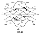
図26は、拡張または展開された幾何学的配置の二重壁ステントシステム2600の側面図を示し、図27は、拡張または展開された幾何学的配置の二重壁ステントシステム2600の端面図を例示している。ステントシステム2600は、外側ステント要素2502(図25の)および外側ステント要素2502に連結される内側ステント要素2004(図20の)を備えている。外側ステント要素2502は、ステントシステムの治療部位への固定を助けるために配置された中間ステントストラット2586および2つのセットのコネクタバンド2580を備えている。中間ステントストラット2586は、拡張すると血管壁に接触するのに十分であると同時に、内側ステント要素2004の血管内の管腔の中心への適切な配置を可能にする拡張直径を有する。中間ステントストラット2586の追加により、血管壁に対するさらなる支持が可能となる。中心流路管腔2721を画定している内側ステント要素2004は、外側ステント要素2502内の径方向の中心に拡張または展開された幾何学的配置で示されている。図26および図27に示されている実施形態は、4つのステントストラットを有する内側ステント要素を備えているが、この内側ステント要素は、システムの所望の全長および/または所望の機械特性によって任意の数のステントストラットを備えることができることを理解されたい。
26 shows a side view of the expanded or deployed geometric double
図28は、本発明の別の実施形態による外側ステント要素を形成するためのレーザーカット部分要素である。レーザーカット部分要素は、平坦に広げられた全体的に円形の外側ステント要素2802として略図で示されているが、当業者であれば、本明細書に開示する部分要素は円筒体として使用されることが意図されていることが解る。本実施の形態においては、長手方向に延在するコネクタは、互いに入れ子状となる螺旋スパー2890である。より具体的には、螺旋スパー2890は、直線近位部分2872、波状または正弦曲線中間部分2874、および直線遠位部分2876を備えている。波状または正弦曲線中間部分2874は、ステントシステムの血管壁への固定をさらに助ける組織の成長を可能にし、かつ展開後のステントの移動を防止する追加の表面積およびポケットの両方を提供する。正弦曲線中間部分2874は、近接する直線セグメントを連結しているクラウン2892と直線セグメントのパターンを有する。谷部2894は、クラウン2892によって形成された開口湾曲部分、すなわちくりぬかれた部分である。螺旋スパー2890の1つ置きのクラウン2892が、近接する螺旋スパー2890の対応する谷部2894内に入れ子状に収容されている。直線近位部分2872および直線遠位部分2876は、ステントストラット2810、2820の直線セグメントの長さにほぼ等しい長さを有するが、正弦曲線中間部分2874は、近位ステントストラット2810を遠位ステントストラット2820に連結するのに少なくとも十分な長さを有する。図28に示されている実施形態は、外側ステント要素2802の近位端部2812および遠位端部2822にフレアステントセグメント1968を備えているが、螺旋スパー2890は、本明細書に開示する外側ステント要素のいずれの実施形態でも長手方向に延在するコネクタとして用いることができることを理解されたい。
FIG. 28 is a laser cut sub-element for forming an outer stent element according to another embodiment of the present invention. Although the laser cut subelement is shown schematically as a flattened, generally circular
図29は、本発明の別の実施形態による外側ステント要素を形成するためのレーザーカット部分要素であり、図30は、図29のレーザーカット部分要素に基づいて形成された外側ステント要素の側面図である。レーザーカット部分要素は、平坦に広げられた全体的に円形の外側ステント要素2902として略図で示されているが、当業者であれば、本明細書に開示する部分要素は円筒体として使用されることが意図されていることが解る。図28の実施形態と同様に、長手方向に延在するコネクタは、第1の螺旋スパーの1つ置きのクラウンが第2の近接する螺旋スパーの対応する谷部内に入れ子状に収容されているという点で、互いに入れ子状の螺旋スパー2990である。しかし、図29の実施形態では、2つの入れ子状螺旋スパー2990が、近位ステントストラット2910のクラウン2914と遠位ステントストラット2920のクラウン2924との間に延在する。したがって、前の実施形態で示した外側ステント要素と比べて、2倍もの長手方向に延在するコネクタが外側ステント要素2990に設けられている。例えば、図29に示されている実施形態では、合計16の螺旋スパー2990が、近位ステントストラット2910と遠位ステントストラット2920との間に設けられている。長手方向に延在するコネクタの数の増加は、ステントシステムの血管壁への固定を助け、血管の径方向の追加支持をさらに提供する。図30に示されているように、螺旋スパー2990は、外側ステント要素の長手方向軸線Laに対して概ね平行に延在していないが、長手方向軸線Laおよび内側ステント要素の周りを螺旋方式に覆うまたは巻いている。本明細書で用いる螺旋方式とは、長手方向軸線Laに対して0よりも大きい所定の角度でステントシステムの近位端部からステントシステムの遠位端部に至る長手方向に延在するコネクタを画定することを意図する。この螺旋の所定角度は、内側ステント要素の拡張および短縮時に長手方向に延在するコネクタが外側に向かって膨らむ/湾曲する程度を減少させる。長手方向に延在するコネクタの外側に向かった膨らみは、長手方向に延在するコネクタの長さに沿って波状または正弦曲線部分を設けることによって達成することができる。波状または正弦曲線部分は、長手方向に延在するコネクタが、内側ステント要素の短縮の減少によるあらゆる利点の喪失を補償できるように、送達前に長くカットして圧縮することができる。加えて、波状または正弦曲線部分は、ステントシステムの血管壁への固定をさらに助ける組織の成長を可能にし、かつ展開後のステントの移動を防止する追加の表面積およびポケットの両方を提供する。図29および図30に示されている実施形態は、外側ステント要素2902の近位端部2912および遠位端部2922にフレアステントセグメント1968を備えているが、螺旋スパー2990は、本明細書に開示する外側ステント要素のいずれの実施形態でも長手方向に延在するコネクタとして用いることができることを理解されたい。
29 is a laser cut sub-element for forming an outer stent element according to another embodiment of the present invention, and FIG. 30 is a side view of an outer stent element formed based on the laser cut sub-element of FIG. It is. Although the laser cut sub-element is shown schematically as a flattened, generally circular
図31は、本発明の別の実施形態による外側ステント要素を形成するためのレーザーカット部分要素である。レーザーカット部分要素は、平坦に広げられた全体的に円形の外側ステント要素3102として略図で示されているが、当業者であれば、本明細書に開示する部分要素は円筒体として使用されることが意図されていることが解る。この実施形態では、長手方向に延在するコネクタは、互いに整合したスパー3196である。より具体的には、スパー3196は、交互直線部分3198および波状または正弦曲線部分3199を備えている。第1のスパー3196の正弦曲線部分3199は、第2の近接するスパー3196の直線部分3198に当接している。図29および図30の実施形態と同様に、外側ステント要素に設けられる長手方向に延在するコネクタの数を増加させるために、2つのスパー3196が、近位ステントストラット3110のクラウン3114と遠位ステントストラット3120のクラウン3124との間に延在する。例えば、図31に示されている実施形態では、合計16の螺旋スパー3196が、近位ステントストラット3110と遠位ステントストラット3120との間に設けられている。長手方向に延在するコネクタの数の増加は、ステントシステムの血管壁への固定を助け、血管の径方向の追加支持をさらに提供する。図31に示されている実施形態は、外側ステント要素3102の近位端部3112および遠位端部3122にフレアステントセグメント1968を備えているが、スパー3196は、本明細書に開示する外側ステント要素のいずれの実施形態でも長手方向に延在するコネクタとして用いることができることを理解されたい。
FIG. 31 is a laser cut sub-element for forming an outer stent element according to another embodiment of the present invention. Although the laser cut subelement is shown schematically as a flattened, generally circular
既に説明した実施形態では、外側ステント要素は、内側ステント要素に取り付けられている。本発明の他の実施形態では、外側ステント要素と内側ステント要素が「浮動式」の構造となるように、外側ステント要素を、内側ステント要素によって緩く捕捉または保持することができる。このような「浮動式」の実施形態では、外側ステント要素の長手方向に延在するコネクタを、内側ステント要素の外面に取り付けられたフックに通すか、または内側ステント要素の近接する最外側のステントストラット間の開口に通すことができる。外側ステント要素と内側ステント要素との間の浮動式連結部は、固定または固着連結部よりも全ステントシステムの形状の一致により柔軟性を提供する。加えて、浮動式連結部は、内側ステント要素によって画定されたステントシステムの内壁と外側ステント要素によって画定されたステントシステムの外壁との間の機械的分離の程度を、既に説明した実施形態よりも大きくする。機械的分離は、一定の直径を有する二次装置の比較的大きなサイズおよび/または不規則な形状の血管内への配置を可能にするため、弁などの一定の直径を有する二次装置をステントシステムの中心流路管腔内に保持するステントシステムにとって重要である。外側ステント要素が、必要な血管壁に対抗する力を与えるが、内側ステント要素に対する機械的な影響を最小にするため、内側ステント要素内に画定されたステントシステムの中心流路管腔の形状またはサイズが変化する可能性が低下する。加えて、浮動式連結部は、外側ステント要素と内側ステント要素との間の応力点を最小限にし、これにより装置の寿命が延びる。浮動式連結部は、ステントシステムの近位端部および遠位端部の両方に配置してもよいし、ステントシステムの一方の端部のみで利用して、例えば、溶接などによって得られる固定連結部をステントシステムの他端に設けてもよい。別の実施形態では、浮動式連結部および固定連結部は、バンド毎に異なってもよい。 In the previously described embodiments, the outer stent element is attached to the inner stent element. In other embodiments of the invention, the outer stent element can be loosely captured or retained by the inner stent element such that the outer and inner stent elements are “floating”. In such a “floating” embodiment, the longitudinally extending connector of the outer stent element is threaded through a hook attached to the outer surface of the inner stent element or the outermost stent adjacent to the inner stent element. Can pass through openings between struts. The floating connection between the outer stent element and the inner stent element provides more flexibility due to the conformity of the shape of the entire stent system than the fixed or anchored connection. In addition, the floating connection provides a greater degree of mechanical separation between the inner wall of the stent system defined by the inner stent element and the outer wall of the stent system defined by the outer stent element than the previously described embodiments. Enlarge. Mechanical separation allows the placement of a secondary device having a constant diameter, such as a valve, to allow placement of a secondary device having a constant diameter within a relatively large size and / or irregularly shaped blood vessel. It is important for a stent system that is retained within the central channel lumen of the system. The outer stent element provides a force against the required vessel wall but minimizes mechanical effects on the inner stent element, so that the shape of the central flow channel lumen of the stent system defined in the inner stent element or The possibility of changing size is reduced. In addition, the floating connection minimizes the stress point between the outer stent element and the inner stent element, thereby extending the life of the device. The floating connection may be located at both the proximal and distal ends of the stent system, or may be utilized at only one end of the stent system, eg, a fixed connection obtained by welding or the like. The portion may be provided at the other end of the stent system. In another embodiment, the floating connection and the fixed connection may be different for each band.
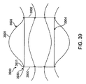
例えば、図39および図39Aは、本発明の別の実施形態による二重壁ステントシステム3900の外側ステント要素3902と内側ステント要素3904との間の「浮動式」またはスライド式連結部3933を例示している。外側ステント要素3902の複数の長手方向に延在するバンドまたはスパー3928が、内側ステント要素3904によって所定の位置に緩く捕捉または保持されており、これにより内側ステント要素3904が外側ステント要素から独立して浮動することが可能である。前の実施形態と同様に、外側ステント要素3902の長手方向に延在するバンドまたはスパー3928の外面がステントシステム3900の外径を画定し、内側ステント要素3904の円筒型管状体が、ステントシステム3900の内径を有する中心流路管腔3921を画定している。中心流路管腔3921は、内部を通る血流を保つために一貫した所定の拡張直径を有する。例えば、一貫した所定の拡張直径は、ステントシステムが埋め込まれる体の血管の通常の直径とほぼ同じにすることができる。内側ステント要素3904は、当業者に周知の任意の適当なステント構造を採用することができ、内部に配置される弁を備えることができる。
For example, FIGS. 39 and 39A illustrate a “floating” or sliding
内側ステント要素3904は、近位端部3930および遠位端部3932を有し、これらの各端部は、外周部に複数のフックまたはループ3931を備えることができる。各フックまたはループ3931は、第1の端部および第2の端部を有する紐またはバンドの材料であり、第1の端部および第2の端部は、内側ステント要素3904の外面に連結されて収容部を画定している。あるいは、1本のフィラメントを内側ステント要素の外周の周りに連続的に編んで複数のフックまたはループを形成することができる。外側ステント要素3902の各バンド3928は、拡張されたときに板ばねのように作用する僅かに湾曲したストリップまたは支持板の材料である。この実施形態では、バンド3928は、内側ステント要素3904の管状体の長さよりも長い。各バンド3928は、一方が近位端部3930に配置され、他方が遠位端部3932に配置された、内側ステント要素3904の対応するフックまたはループ3931のセットによって画定された収容部に個別に「通される」または配置されている。この方式では、各バンド3928の近位端部は、内側ステント要素3904の近位端部3930の近位側に延び、各バンド3928の遠位端部は、内側ステント要素3904の遠位端部3932の遠位側に延びている。各バンド3928の端部は、治療部位に対する前進および探索の際に複数のフックまたはループ3931内に外側ステント要素3902を捕捉または維持するためにバンド3928が正弦曲線形状を有するように、径方向外側に向かって僅かに湾曲している。バンド3928は、フックまたはループ3931によって画定された収容部を通過するには大きすぎる幅を各バンドの一部が有するようにバンドのサイズを変更することによって、またはフックまたはループ3931によって画定された収容部を通過するのが困難または可能性が低いジグザグなどの形状を各バンドの一部が有するようにバンドの形状を変更することによって、またはバンドを内側ステント要素に対して安定させるために個々のバンド3928間の間隙に跨るように内側ステント要素3904の外周の周りに連続的に編まれた別個の織物または他の基質の追加によって、複数のフックまたはループ3931内に追加または別法として保持することできる。内側ステント要素3904は、外側ステント要素3902のバンド3928の内側の中心または内部に位置されるが、外側ステント要素3902に固着されてはいない。むしろ、浮動式連結部3933は、2つの要素間に配置されており、外側ステント要素3902のバンド3928が、内側ステント要素3904の近位端部3930および遠位端部3932の外周の周りに配置された複数のフックまたはループ3931によって所定の位置に緩く捕捉または保持されている。したがって、内側ステント要素3904は、外側ステント要素3902から独立して「浮動」または移動することができる。
外側ステント要素が内側ステント要素に固着される既に説明した実施形態では、外側ステント要素は、内側ステント要素の短縮動力学によって展開または径方向に拡張される。しかし、「浮動式」構造では、外側ステント要素3902の長手方向に延在するバンド3928が、自己拡張して径方向外向きに湾曲し、血管壁に接触してステントシステム3900の治療部位への固定を助ける。例えば、一実施形態では、自己拡張型外側ステント要素3902の展開は、ニッケル‐チタン(ニチノール)などの材料の形状記憶特性を利用することによって容易にすることができる。形状記憶金属は、特定の温度または応力条件に曝されると規定された形状またはサイズに戻る能力を有する金属組成物群である。形状記憶金属は、一般に、比較的低い温度で変形させることができ、比較的高い温度に曝されると、それらが変形前に有していた規定された形状またはサイズに戻る。このため、ステント要素がin vivoで高い温度、すなわち体温または加熱流体に曝露されると、その「記憶した」曲線形状に戻るように、ステント要素を、変形された直線の状態で体の中に挿入することができる。治療または展開部位に配置されると、外側ステント要素3902の長手方向に延在するバンド3928が、加熱形状の形態となり、血管壁に接触して、血管に必要な対抗する力を与える。
In the previously described embodiments in which the outer stent element is secured to the inner stent element, the outer stent element is deployed or radially expanded due to the shortening dynamics of the inner stent element. However, in the “floating” configuration, the longitudinally extending
別の実施形態では、自己拡張型外側ステント要素3902の展開は、自己拡張型ばね式またはニッケル‐チタン(ニチノール)などの超弾性材料を利用することによって容易にすることができる。自己拡張型外側ステント要素3902は、血管内に送達するための送達カテーテルに対して、拡張した形状から収縮または圧縮された幾何学的配置に折り畳むまたはクリンプすることができる。ステントシステムを折り畳まれた形状に保持するスリーブまたはシースが除去されると、外側ステント要素3902は、血管内の治療部位で拡張または展開された状態をとる。内側ステント要素3904は、バルーン拡張型または自己拡張型とすることができる。前の実施形態では、内側ステント要素3904の外面は、血管壁に殆どまたは全く接触せず、むしろ外側ステント要素3902内の中心に維持される。内側ステント要素3904は、中心流路管腔3921が血管内の径方向の中心に位置するように構成されている。
In another embodiment, deployment of the self-expanding
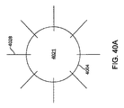
本発明の別の「浮動式」の実施形態では、外側ステント要素の長手方向に延在するコネクタは、内側ステント要素の最外側ステントストラット間の開口に通すことができる。例えば、図40および図40Aは、外側ステント要素4002と内側ステント要素4004との間の「浮動式」またはスライド式連結部4033を例示している。上の実施形態と同様に、外側ステント要素4002の長手方向に延在するバンドまたはスパー4028は、ステントシステム4000の外径を画定している。当業者に周知の任意の適当なステント構造を採用することができ、内部に配置される弁を備えることができる内側ステント要素4004は、ステントシステム4000の中心流路管腔4021を画定している。複数の近接するステントストラット4034は、内側ステント要素4004の円筒型管状体の形状に形成するように整合されている。外側ステント要素4002の複数の長手方向に延在するバンドまたはスパー4028は、浮動式連結部4033を形成するために、近接するステントストラット4034間の開口に通されている。より具体的には、各バンド4028の近位部分は、内側ステント要素4004の近位端部の近接するステントストラット4034間の開口に通され、各バンド4028の遠位部分は、内側ステント要素4004の遠位端部の近接するステントストラット4034間の開口に通されている。バンド4028の端部は、治療部位に対する前進および探索の際に内側ステント要素4004の近接するステントストラットによって画定された開口内に外側ステント要素4002を捕捉または維持するためにバンド4028が正弦曲線形状を有するように、径方向外側に向かって僅かに湾曲している。さらに、別個の織物または他の基質を、バンドを内側ステント要素に対して安定させるために個々のバンド4028間の間隙に跨るように内側ステント要素4004の外周の周りに連続的に編むことができる。外側ステント要素4002のバンド4028は、上記したバンド3928のように自己拡張型である。
In another “floating” embodiment of the present invention, the longitudinally extending connector of the outer stent element can be threaded through an opening between the outermost stent struts of the inner stent element. For example, FIGS. 40 and 40A illustrate a “floating” or sliding
本発明のいずれの実施形態でも、内側ステント要素は、内部を通る流れを制御する弁を内部に備えることができることを理解されたい。図32は、一方向の流れを遮断できる弁3236を内部に備えた内側ステント要素3204を示している。内側ステント要素の前の実施形態で説明したように、内側ステント要素3204は、円筒型管状体を形成するために長手方向軸線Laに対して実質的に平行に整合された複数の近接するステントストラット3234を備えている。加えて、内側ステント要素3204は、その内面に密閉して恒久的に取り付けられた弁3236および/または内側ステント要素3204の複数のステントストラット3234を取り囲むまたは裏打ちするグラフト材料3240を備えている。弁3236は、ヒトに使用するために処理および調製されたウシまたはブタの弁としてもよいし、機械弁または人工リーフレット弁としてもよい。グラフト材料3240は、内側ステント要素3204に取り付けられたときに一方向流路を形成するポリエステル、Dacron繊維、またはPTFEなどの低空隙率織物とすることができる。例えば、内側ステント要素は、参照によりその開示内容が本明細書に組み入れられるLeonhardtらによる「Percutaneous Placement Valve Stent」という名称の米国特許第5,957,949号に開示されているような、ヒトに使用するために処理および調製され、レーザー溶接ステント内に縫い付けられた、経皮的に埋め込まれるウシまたはブタの弁から構成することができる。本発明の二重壁ステントシステムは、外側ステント要素が患者の成長を許容し、かつ/または上記説明したように体の管腔の異常を調節するため、右心室流出路での使用に特に適している。したがって、右心室流出路の異常を治療する場合は、内側ステント要素としてステント弁を利用することが望ましいであろう。しかし、本発明の二重壁ステントシステムは、このステントシステムが有用と見なされるあらゆる他の症状の治療のために、内部に弁を用いずに利用することもできる。内側ステント要素の特殊な構造にかかわらず、外側ステント要素は、体の管腔の成長および/または異常に合わせるために径方向外向きに湾曲して、二重壁ステントシステムを体の管腔の所定の位置に固定する働きをする。したがって、内側ステント要素は、外側ステント要素に接続するように構成されているのであれば、当業者に周知の任意の適当なステントとすることができる。
It should be understood that in any embodiment of the present invention, the inner stent element can be internally provided with a valve that controls the flow therethrough. FIG. 32 shows an
本発明による様々な実施形態を上記説明したが、これらの実施形態は、限定ではなく例示目的で単なる例として示したものであることを理解されたい。当業者には、本発明の趣旨および範囲から逸脱することなく、形態および細部の様々な変更が、本発明の範囲内で可能であることが明らかであろう。したがって、本発明の広さと範囲は、上記説明した例示的な実施形態のいずれによっても限定されるものではなく、添付の特許請求の範囲およびその均等物によってのみ規定されるべきである。また、本明細書に記載した各実施形態および本明細書で言及した各参考文献の各特徴は、あらゆる他の実施形態の特徴と組み合わせて用いることができることも理解されたい。本明細書に記載したすべての特許および刊行物は、参照によりその全容が本明細書に組み入れられる。 Although various embodiments according to the present invention have been described above, it should be understood that these embodiments are presented by way of example only and not limitation. It will be apparent to those skilled in the art that various modifications, in form and detail, are possible within the scope of the invention without departing from the spirit and scope of the invention. Accordingly, the breadth and scope of the present invention should not be limited by any of the above-described exemplary embodiments, but should be defined only in accordance with the appended claims and their equivalents. It is also to be understood that each embodiment described herein and each feature of each reference mentioned herein can be used in combination with the features of any other embodiment. All patents and publications mentioned herein are hereby incorporated by reference in their entirety.
Claims (13)
近位端部、遠位端部、および内部を通る中心流路管腔を画定している全体的に管状の円筒本体を有する内側ステント要素と、
前記内側ステント要素の前記管状の円筒本体の周りに径方向に配置された複数の長手方向に延在するコネクタを有する外側ステント要素と、
前記外側ステント要素を、固着するのではなくスライド可能に前記内側ステント要素に取り付けるための手段と、を備え、
前記ステントシステムが径方向に拡張された幾何学的配置をとった場合は、前記外側ステント要素の前記長手方向に延在するコネクタが、前記体の管腔の血管壁に対して径方向外向きに湾曲するように構成され、前記内側ステント要素が、前記外側ステント要素の前記長手方向に延在するコネクタ内に径方向に位置する、
ことを特徴とするステントシステム。 A stent system for use in a body lumen comprising:
An inner stent element having a generally tubular cylindrical body defining a proximal end, a distal end, and a central channel lumen therethrough;
An outer stent element having a plurality of longitudinally extending connectors radially disposed about the tubular cylindrical body of the inner stent element;
Means for attaching the outer stent element to the inner stent element slidably rather than anchoring;
When the stent system has a radially expanded geometry, the longitudinally extending connector of the outer stent element is radially outward with respect to the vessel wall of the body lumen. The inner stent element is radially located within the longitudinally extending connector of the outer stent element,
A stent system characterized by the above.
請求項1に記載のステントシステム。 The means for attaching comprises at least one hook disposed on an outer surface of the inner stent element, the hook defining a receiving portion for receiving a longitudinally extending connector;
The stent system according to claim 1.
請求項2に記載のステントシステム。 The at least one hook includes a lace material having a first end and a second end, the first end and the second end being coupled to the inner stent element and the Defining the containment part,
The stent system according to claim 2.
請求項2に記載のステントシステム。 A filament is knitted around the outer periphery of the inner stent element to define a plurality of hooks;
The stent system according to claim 2.
請求項1に記載のステントシステム。 The means for attaching includes a portion of each longitudinally extending connector threaded through an opening in the inner stent element;
The stent system according to claim 1.
請求項5に記載のステントシステム。 The inner stent element comprises a plurality of adjacent stent struts aligned to form a tubular cylinder thereof, and a proximal portion of the longitudinally extending connector is provided near the inner stent element. A distal portion of the longitudinally extending connector is passed through the openings between the plurality of adjacent stent struts at the distal end and the plurality of adjacent stents at the distal end of the inner stent element Passed through the opening between the struts,
The stent system according to claim 5.
請求項1に記載のステントシステム。 A proximal end of each longitudinally extending connector extends proximally of a proximal end of the inner stent element, and a distal end of each longitudinally extending connector is the inner Extending distally of the distal end of the stent element,
The stent system according to claim 1.
請求項7に記載のステントシステム。 The inner stent element is centrally located longitudinally between the proximal and distal ends of the longitudinally extending connector;
The stent system according to claim 7.
請求項1に記載のステントシステム。 The connector extending in each longitudinal direction is a band having a first end and a second end, and the first end and the second end of the band are radially outward. Slightly curved,
The stent system according to claim 1.
請求項1に記載のステントシステム。 The longitudinally extending connector is self-expanding,
The stent system according to claim 1.
請求項1に記載のステントシステム。 In the radially expanded geometry, the longitudinally extending connector of the outer stent element causes the inner stent element to make little or no contact with the wall of the body lumen. Radially expanded larger than the stent element,
The stent system according to claim 1.
請求項1に記載のステントシステム。 The longitudinally extending connector extends generally parallel to a longitudinal axis of the outer stent element;
The stent system according to claim 1.
請求項1に記載のステントシステム。 A valve disposed within the central channel lumen of the inner stent element, further comprising a non-porous graft material covering at least a portion of the inner stent element;
The stent system according to claim 1.
Applications Claiming Priority (3)
| Application Number | Priority Date | Filing Date | Title |
|---|---|---|---|
| US12/060,340 US7806919B2 (en) | 2008-04-01 | 2008-04-01 | Double-walled stent system |
| US12/060,340 | 2008-04-01 | ||
| PCT/US2009/037368 WO2009123852A1 (en) | 2008-04-01 | 2009-03-17 | Double-walled stent system |
Publications (3)
| Publication Number | Publication Date |
|---|---|
| JP2011516157A JP2011516157A (en) | 2011-05-26 |
| JP2011516157A5 JP2011516157A5 (en) | 2012-05-10 |
| JP5537540B2 true JP5537540B2 (en) | 2014-07-02 |
Family
ID=44193848
Family Applications (1)
| Application Number | Title | Priority Date | Filing Date |
|---|---|---|---|
| JP2011503021A Active JP5537540B2 (en) | 2008-04-01 | 2009-03-17 | Double wall stent system |
Country Status (1)
| Country | Link |
|---|---|
| JP (1) | JP5537540B2 (en) |
Families Citing this family (1)
| Publication number | Priority date | Publication date | Assignee | Title |
|---|---|---|---|---|
| CN105705118B (en) * | 2013-09-12 | 2018-03-30 | 波士顿科学国际有限公司 | Support with anti-displacement connector |
Family Cites Families (4)
| Publication number | Priority date | Publication date | Assignee | Title |
|---|---|---|---|---|
| US5064435A (en) * | 1990-06-28 | 1991-11-12 | Schneider (Usa) Inc. | Self-expanding prosthesis having stable axial length |
| US7060089B2 (en) * | 2002-01-23 | 2006-06-13 | Boston Scientific Scimed, Inc. | Multi-layer stent |
| AU2002951203A0 (en) * | 2002-09-05 | 2002-09-19 | Cocks, Graeme | Modular stent system and delivery means |
| US20050222674A1 (en) * | 2004-03-31 | 2005-10-06 | Med Institute, Inc. | Endoluminal graft with a prosthetic valve |
-
2009
- 2009-03-17 JP JP2011503021A patent/JP5537540B2/en active Active
Also Published As
| Publication number | Publication date |
|---|---|
| JP2011516157A (en) | 2011-05-26 |
Similar Documents
| Publication | Publication Date | Title |
|---|---|---|
| EP2285318B1 (en) | Double-walled stent system | |
| AU2016203206B2 (en) | System and method for assembling a folded percutaneous valve | |
| US8128686B2 (en) | Branched vessel prosthesis | |
| JP5491491B2 (en) | Stent prosthesis with selective flared crown | |
| US10154916B2 (en) | Articulated commissure valve stents and methods | |
| US7377938B2 (en) | Prosthetic cardiac value and method for making same | |
| AU2006251888B2 (en) | Apparatus and methods for repairing the function of a diseased valve and method for making same | |
| US8123794B2 (en) | Intraluminal support frame | |
| CN115697255A (en) | Inflatable instruments and related systems and methods | |
| JP5309207B2 (en) | Double wall stent system | |
| US10335272B2 (en) | Apparatus and method for repairing the function of a diseased valve | |
| JP5537540B2 (en) | Double wall stent system |
Legal Events
| Date | Code | Title | Description |
|---|---|---|---|
| A521 | Request for written amendment filed |
Free format text: JAPANESE INTERMEDIATE CODE: A523 Effective date: 20120316 |
|
| A621 | Written request for application examination |
Free format text: JAPANESE INTERMEDIATE CODE: A621 Effective date: 20120316 |
|
| A977 | Report on retrieval |
Free format text: JAPANESE INTERMEDIATE CODE: A971007 Effective date: 20130527 |
|
| A131 | Notification of reasons for refusal |
Free format text: JAPANESE INTERMEDIATE CODE: A131 Effective date: 20130605 |
|
| A601 | Written request for extension of time |
Free format text: JAPANESE INTERMEDIATE CODE: A601 Effective date: 20130905 |
|
| A602 | Written permission of extension of time |
Free format text: JAPANESE INTERMEDIATE CODE: A602 Effective date: 20130912 |
|
| A521 | Request for written amendment filed |
Free format text: JAPANESE INTERMEDIATE CODE: A523 Effective date: 20131021 |
|
| TRDD | Decision of grant or rejection written | ||
| A01 | Written decision to grant a patent or to grant a registration (utility model) |
Free format text: JAPANESE INTERMEDIATE CODE: A01 Effective date: 20140423 |
|
| R150 | Certificate of patent or registration of utility model |
Ref document number: 5537540 Country of ref document: JP Free format text: JAPANESE INTERMEDIATE CODE: R150 |
|
| A61 | First payment of annual fees (during grant procedure) |
Free format text: JAPANESE INTERMEDIATE CODE: A61 Effective date: 20140425 |
|
| R250 | Receipt of annual fees |
Free format text: JAPANESE INTERMEDIATE CODE: R250 |
|
| R250 | Receipt of annual fees |
Free format text: JAPANESE INTERMEDIATE CODE: R250 |
|
| R250 | Receipt of annual fees |
Free format text: JAPANESE INTERMEDIATE CODE: R250 |
|
| R250 | Receipt of annual fees |
Free format text: JAPANESE INTERMEDIATE CODE: R250 |
|
| R250 | Receipt of annual fees |
Free format text: JAPANESE INTERMEDIATE CODE: R250 |
|
| R250 | Receipt of annual fees |
Free format text: JAPANESE INTERMEDIATE CODE: R250 |
|
| R250 | Receipt of annual fees |
Free format text: JAPANESE INTERMEDIATE CODE: R250 |