JP5536404B2 - Movable accessory device - Google Patents

Movable accessory device Download PDF

Info

Publication number
JP5536404B2
JP5536404B2 JP2009221103A JP2009221103A JP5536404B2 JP 5536404 B2 JP5536404 B2 JP 5536404B2 JP 2009221103 A JP2009221103 A JP 2009221103A JP 2009221103 A JP2009221103 A JP 2009221103A JP 5536404 B2 JP5536404 B2 JP 5536404B2
Authority
JP
Japan
Prior art keywords
pair
end side
slide
slide plates
plate
Prior art date
Legal status (The legal status is an assumption and is not a legal conclusion. Google has not performed a legal analysis and makes no representation as to the accuracy of the status listed.)
Expired - Fee Related
Application number
JP2009221103A
Other languages
Japanese (ja)
Other versions
JP2011067406A (en
JP2011067406A5 (en
Inventor
涼介 鈴木
Current Assignee (The listed assignees may be inaccurate. Google has not performed a legal analysis and makes no representation or warranty as to the accuracy of the list.)
Heiwa Corp
Original Assignee
Heiwa Corp
Priority date (The priority date is an assumption and is not a legal conclusion. Google has not performed a legal analysis and makes no representation as to the accuracy of the date listed.)
Filing date
Publication date
Application filed by Heiwa Corp filed Critical Heiwa Corp
Priority to JP2009221103A priority Critical patent/JP5536404B2/en
Publication of JP2011067406A publication Critical patent/JP2011067406A/en
Publication of JP2011067406A5 publication Critical patent/JP2011067406A5/ja
Application granted granted Critical
Publication of JP5536404B2 publication Critical patent/JP5536404B2/en
Expired - Fee Related legal-status Critical Current
Anticipated expiration legal-status Critical

Links

Images

Landscapes

  • Pinball Game Machines (AREA)

Description

本発明は、弾球遊技機に備えられる可動役物装置に係り、特に、一対のスライド板が可変表示装置の表示画面の前方を近接および離反方向へ移動可能となっている可動役物装置に関するものである。   The present invention relates to a movable accessory device provided in a ball game machine, and more particularly to a movable accessory device in which a pair of slide plates can move in the proximity and separation directions in front of a display screen of a variable display device. Is.

パチンコ機に代表される弾球遊技機の中には、遊技盤の遊技領域に可変表示装置や始動入賞口を配設し、遊技領域に向けて発射された遊技球が始動入賞口に入球することを契機に電子抽選を行い、その抽選結果に基づいて可変表示装置が図柄の変動表示および停止表示を行うようにした機種が存在する。電子抽選の抽選結果には当たり(当選)とハズレ(非当選)があり、抽選結果が当たりの場合には、可変表示装置の表示画面に所定の特別図柄の組み合わせが表示され、通常モードから特別遊技モードへと移行する。この特別遊技モードでは、例えばアタッカーを開放動作して露呈される大入賞口に遊技球が入るので、遊技者は多くの賞球を獲得できるようになっている。   In some ball game machines represented by pachinko machines, a variable display device and a start prize opening are arranged in the game area of the game board, and the game balls launched toward the game area enter the start prize opening. There is a model in which electronic lottery is performed in response to this, and the variable display device performs variable display and stop display of symbols based on the lottery result. Electronic lottery results include winning (winning) and losing (non-winning). When the lottery results are winning, a special combination of symbols is displayed on the display screen of the variable display device. Transition to game mode. In this special game mode, for example, a game ball enters a big winning opening exposed by opening an attacker, so that the player can acquire many prize balls.

このような弾球遊技機において、可動態様を変化させることができる可動体を遊技領域の適宜位置(例えば可変表示装置の周囲)に配置し、電子抽選で当選していることを遊技者に可動体の可動態様によって示唆するようにした可動役物装置が広く採用されている。かかる可動役物装置は、モータやソレノイド等からなるアクチュエータと、このアクチュエータを駆動源として種々の運動を行う可動体とを備えており、従来より、スロットマシンのリールユニット上方に設けられた可変表示装置の左右両側に一対のスライド板を配置し、これらスライド板を可変表示装置の表示画面の前方で往復移動させるようにした可動役物装置が知られている(例えば、特許文献1参照)。   In such a ball game machine, a movable body capable of changing the movable mode is arranged at an appropriate position in the game area (for example, around the variable display device), and it is movable to the player that the player is elected by electronic lottery. Movable accessory devices that are suggested by the manner in which the body moves are widely used. Such a movable accessory device includes an actuator composed of a motor, a solenoid, and the like, and a movable body that performs various motions using this actuator as a drive source. Conventionally, a variable display provided above the reel unit of the slot machine. There is known a movable accessory device in which a pair of slide plates are arranged on both the left and right sides of the device, and these slide plates are reciprocated in front of a display screen of a variable display device (see, for example, Patent Document 1).

特許文献1に開示された可動役物装置では、一対のスライド板と一対のモータが可変表示装置の左右両側に配置されており、通常、これらスライド板は表示画面の前方を開放する退避位置に保持されている。スライド板の上辺または下辺には側方へ突出するラックが設けられており、モータの出力軸に取り付けられたピニオンが対応するスライド板のラックと噛合している。一対のスライド板が退避位置にあるとき、ピニオンはラックの基端側と噛合しており、この状態でモータを正逆いずれかの方向へ回転すると、ピニオンとラックの噛合部分が基端側から先端側へ移行し、それに伴って両スライド板が退避位置から表示画面の中央部に向かって移動する。そして、両スライド板の対向面同士が当接した近接位置でモータの回転を停止すると、表示画面の前方が一対のスライド板によって遮蔽された状態になる。また、一対のスライド板が近接位置にあるときにモータを上記と逆方向へ回転すると、ピニオンとラックの噛合部分が先端側から基端側へ移行し、それに伴って両スライド板が近接位置から離反方向へ移動して退避位置で停止するため、表示画面の前方が開放された初期状態に戻る。   In the movable accessory device disclosed in Patent Document 1, a pair of slide plates and a pair of motors are disposed on both the left and right sides of the variable display device. Normally, these slide plates are in a retracted position that opens the front of the display screen. Is retained. A rack projecting sideways is provided on the upper or lower side of the slide plate, and a pinion attached to the output shaft of the motor meshes with the corresponding slide plate rack. When the pair of slide plates are in the retracted position, the pinion is meshed with the base end side of the rack, and when the motor is rotated in either the forward or reverse direction in this state, the meshed portion of the pinion and rack is moved from the base end side. As a result, the slide plates move from the retracted position toward the center of the display screen. Then, when the rotation of the motor is stopped at the close position where the opposing surfaces of the slide plates are in contact with each other, the front of the display screen is shielded by the pair of slide plates. Also, if the motor is rotated in the opposite direction when the pair of slide plates are in the close position, the meshing portion of the pinion and the rack moves from the front end side to the base end side, and accordingly both slide plates are moved from the close position. Since it moves in the direction of separation and stops at the retracted position, it returns to the initial state where the front of the display screen is opened.

特開2005−40413号公報JP 2005-40413 A

ところで、前述した従来の可動役物装置は、スライド板の上下いずれか一方に突設されたラックを介してモータの駆動力が伝達されるようになっているため、一対のスライド板が表示画面の前方を遮蔽する近接位置で停止しているとき、ラックの延長線上にある駆動端側はモータの駆動力によって確実に当接させることができるものの、モータの駆動力が直接付与されない自由端側の対向面間に不所望な隙間ができてしまい、この隙間から表示画面の一部が露呈してしまうという問題があった。特に、可変表示装置の大型化に伴って表示画面の上下方向の寸法が長くなると、スライド板の自由端が駆動端から遠く離れてしまい、自由端側に作用するモータの駆動力が大幅に低下してしまうため、上記したような問題は顕著なものとなる。   By the way, the conventional movable accessory device described above is configured such that the driving force of the motor is transmitted via a rack protruding on either the upper or lower side of the slide plate. The drive end side on the extension line of the rack can be reliably brought into contact with the drive force of the motor when it is stopped at a close position that shields the front of the motor, but the free end side where the drive force of the motor is not directly applied There is a problem that an undesired gap is formed between the opposing surfaces of the display screen, and a part of the display screen is exposed from the gap. In particular, if the vertical dimension of the display screen becomes longer as the size of the variable display device increases, the free end of the slide plate moves away from the drive end, and the driving force of the motor acting on the free end side is greatly reduced. For this reason, the above-described problems become remarkable.

本発明は、このような従来技術の実情に鑑みてなされたもので、その目的は、一対のスライド板によって可変表示装置の前方を見栄え良く開閉することができる可動役物装置を提供することにある。   The present invention has been made in view of the actual situation of the prior art, and an object of the present invention is to provide a movable accessory device that can open and close the front of the variable display device with a pair of slide plates. is there.

上記の目的を達成するために、本発明は、遊技盤の遊技領域に設けられた可変表示装置と、この可変表示装置の表示画面の前方を近接および離反する方向へ移動可能な一対のスライド板と、これらスライド板を一方端側から駆動力を付与して個別に移動させる一対の駆動装置とを備え、一対のスライド板の他方端側を駆動力の付与されない自由端側として構成した可動役物装置において、一対のスライド板は、互いに最も離反する退避位置で、自由端側の対向間距離に対して駆動力の付与される駆動端側の対向間距離が広くなる初期姿勢に設定されており、駆動力によって一対のスライド板を退避位置から近接方向へ移動するとき、自由端側のコーナ部同士が当接するまで前記初期姿勢を維持したまま一対のスライド板の移動を続行し、自由端側のコーナ部同士が当接した後も駆動力によって一対のスライド板の移動をさらに続行し、駆動端側のコーナ部同士が当接した位置で一対のスライド板の移動を停止して、一対のスライド板の対向面同士を接触させた状態にするように構成した。 In order to achieve the above object, the present invention provides a variable display device provided in a game area of a game board, and a pair of slide plates that can move in the direction of approaching and separating from the front of the display screen of the variable display device. And a pair of driving devices that individually move the slide plates by applying a driving force from one end side, and a movable combination in which the other end side of the pair of sliding plates is configured as a free end side to which no driving force is applied. In the object apparatus, the pair of slide plates are set in an initial posture in which the distance between the opposing ends on the driving end side to which driving force is applied is larger than the distance between the opposing ends on the free end side at a retreat position farthest from each other. cage, when moving from the retracted position a pair of slide plates by the driving force to a close direction, the corner portions of the free end side to continue the movement of the pair of slide plates while maintaining the initial posture until abutment, the free After the corner portions of the side is in contact with also further continue the movement of the pair of slide plates by the driving force, it stops the movement of the pair of slide plates at a position where the corner portions of the driving end is in contact with a pair It was comprised so that the opposing surfaces of the slide plate might be made to contact .

このように構成された可動役物装置では、一対の駆動装置の駆動力によって対応するスライド板を近接方向へ移動する際、まず両者の自由端側のコーナ部同士が当接するが、この時点で駆動端側のコーナ部同士はまだ当接しておらず、一対のスライド板の対向面間に駆動端側を底辺とする正面視三角形状の間隙が形成される。そして、この状態から両スライド板を近接方向へさらに移動すると、自由端側を当接したまま駆動端側が近接することで前記間隙が次第に狭くなっていき、駆動端側のコーナ部同士が当接した時点で両スライド板を停止させる。その結果、両スライド板の対向面同士が駆動端側から自由端側に至る全ての部分で隙間なく当接し、可変表示装置の表示画面を一対のスライド板によって確実に遮蔽することができる。   In the movable accessory device configured as described above, when the corresponding slide plate is moved in the proximity direction by the driving force of the pair of driving devices, the corner portions on the free end sides of the two first come into contact with each other. The corners on the drive end side are not yet in contact with each other, and a triangular gap in front view with the drive end side as the base is formed between the opposed surfaces of the pair of slide plates. When the slide plates are further moved in the proximity direction from this state, the drive end side approaches while the free end side is in contact with each other, so that the gap is gradually narrowed, and the corner portions on the drive end side contact each other. At that time, both slide plates are stopped. As a result, the opposing surfaces of both slide plates are in contact with each other from the drive end side to the free end side without any gap, and the display screen of the variable display device can be reliably shielded by the pair of slide plates.

上記の構成において、駆動装置が、スライド板を軸線方向へ往復移動させるスクリューシャフトと、このスクリューシャフトを正逆両方向へ回転させるモータとを備え、スライド板の駆動端側にスクリューシャフトに嵌挿されるガイド筒体を設け、モータが搭載された基体にスクリューシャフトの軸線方向へ延びるガイド部を形成し、このガイド部に一対のスライド板の自由端側を摺動可能に係合させると、スライド板がスクリューシャフトの回転方向へ供回りしなくなるので、スライド板をスクリューシャフトの軸線方向へスムーズに往復移動させることができる。 In the above configuration, the drive device includes a screw shaft that reciprocally moves the slide plate in the axial direction and a motor that rotates the screw shaft in both forward and reverse directions, and is fitted into the screw shaft on the drive end side of the slide plate. When a guide cylinder is provided, a guide portion extending in the axial direction of the screw shaft is formed on the base on which the motor is mounted, and the free end side of the pair of slide plates is slidably engaged with the guide portion, the slide plate Can no longer be rotated in the rotational direction of the screw shaft, so that the slide plate can be smoothly reciprocated in the axial direction of the screw shaft.

また、上記の構成において、一対のスライド板のいずれか一方の自由端側に磁石が固着されると共に、他方の自由端側に磁石に吸着可能な磁性体が固着されていると、自由端側のコーナ部同士の当接が磁石の吸引力によってアシストされるため、両スライド板の対向面同士をより確実に当接させることができる。   In the above configuration, when a magnet is fixed to one free end side of the pair of slide plates and a magnetic body that can be attracted to the magnet is fixed to the other free end side, the free end side Since the contact between the corner portions is assisted by the attractive force of the magnet, the opposing surfaces of both slide plates can be contacted more reliably.

また、上記の構成において、前記基体である回転板と、この回転板を遊技盤の盤面と略平行な面内で正逆両方向へ回転させる回転駆動機構とを備え、回転板に可変表示装置の表示画面を目視可能な矩形状の開口が設けられ、一対の駆動装置が回転板に搭載されていると共に、一対のスライド板が開口を介して回転板に対向配置されていると、回転板の回転動作に応じて表示画面との相対角度を変える矩形状の開口内に一対のスライド板が出入するという、これまでにない斬新でインパクトのある演出を実現することができる。 Further, in the above configuration, the rotating plate as the base, and a rotation driving mechanism that rotates the rotating plate in both forward and reverse directions within a plane substantially parallel to the board surface of the game board , the rotating plate includes a variable display device. A rectangular opening that allows viewing of the display screen is provided, and when the pair of drive devices are mounted on the rotating plate and the pair of slide plates are arranged to face the rotating plate through the opening, An unprecedented and impactful production in which a pair of slide plates enter and exit in a rectangular opening that changes the relative angle with the display screen in accordance with the rotation operation can be realized.

本発明の可動役物装置は、一対のスライド板がそれぞれ対応する駆動装置の駆動力を受けて近接方向へ移動する際、その移動途中で自由端側のコーナ部同士が当接したときに、駆動端側のコーナ部同士が当接しないように意図的に間隙を形成し、しかる後、この間隙を両スライド板のさらなる移動(オーバーストローク)に伴って狭めていくことにより、駆動端側のコーナ部同士が当接するようにしたので、両スライド板の対向面同士を隙間なく確実に密着させることができ、一対のスライド板の往復移動によって可変表示装置の前方を見栄え良く開閉することができる。   When the movable accessory device of the present invention receives a driving force of the corresponding driving device and moves in the proximity direction, when the corner portions on the free end side come into contact with each other during the movement, A gap is intentionally formed so that the corners on the drive end side do not come into contact with each other, and then the gap is narrowed along with further movement (overstroke) of both slide plates, so that Since the corner portions are in contact with each other, the opposing surfaces of both slide plates can be reliably brought into close contact with each other, and the front and rear of the variable display device can be opened and closed with good appearance by the reciprocating movement of the pair of slide plates. .

パチンコ機の外観を示す斜視図である。It is a perspective view which shows the external appearance of a pachinko machine. 図1のパチンコ機に備えられる遊技盤の正面図である。It is a front view of the game board with which the pachinko machine of FIG. 1 is equipped. 本発明の実施形態例に係る可動役物装置の正面図である。It is a front view of the movable accessory apparatus which concerns on the example of embodiment of this invention. 該可動役物装置の背面図である。It is a rear view of this movable accessory apparatus. 該可動役物装置に備えられる支持ベースの正面図である。It is a front view of the support base with which this movable accessory apparatus is equipped. 図3のA−A線に沿う断面図である。It is sectional drawing which follows the AA line of FIG. 該可動役物装置に備えられる回転板の正面図である。It is a front view of the rotating plate with which this movable accessory apparatus is equipped. 該回転板の背面図である。It is a rear view of the rotating plate. 該回転板に装飾カバーを取り付けた状態を示す縦断面図である。It is a longitudinal cross-sectional view which shows the state which attached the decorative cover to this rotary plate. 該可動役物装置に備えられるスライド板と駆動機構の正面図である。It is a front view of the slide board and drive mechanism with which this movable accessory apparatus is equipped. 該駆動機構の平面図である。It is a top view of this drive mechanism. 該スライド板の退避状態を示す斜視図である。It is a perspective view which shows the retracted state of this slide plate. 該スライド板の移動途中状態を示す斜視図である。It is a perspective view which shows the movement middle state of this slide plate. 該スライド板の近接状態を示す斜視図である。It is a perspective view which shows the proximity | contact state of this slide board. 該スライド板の近接直前状態を示す正面図である。It is a front view which shows the state immediately before proximity | contact of this slide plate. 該スライド板の近接状態を示す正面図である。It is a front view which shows the proximity | contact state of this slide board. 該可動役物装置に備えられるケーブルガイドの斜視図である。It is a perspective view of the cable guide with which this movable accessory apparatus is equipped. 該ケーブルガイドの断面図である。It is sectional drawing of this cable guide. 該回転板が初期位置にある状態を示す正面図である。It is a front view which shows the state which this rotary plate exists in an initial position. 該回転板が時計方向の末端位置へ回転した状態を示す正面図である。It is a front view which shows the state which this rotary plate rotated to the terminal position of clockwise direction. 該回転板が反時計方向の末端位置へ回転した状態を示す正面図である。It is a front view which shows the state which this rotary plate rotated to the terminal position of the counterclockwise direction.

発明の実施の形態について図面を参照して説明する。図1に示すように、本発明の可動役物装置が適用されたパチンコ機pは、遊技場の島設備に配置される機枠1と、機枠1に扉状に開閉自在に取り付けられた前面枠2と、前面枠2に収納保持された後述する遊技盤3と、前面枠2の前面に扉状に開閉自在に取り付けられたガラス扉4と、前面枠2の下方に配設された前面ボード5と、前面ボード5に取り付けられた発射ハンドル6等を具備しており、前面ボード5には受け皿7が設けられている。   Embodiments of the invention will be described with reference to the drawings. As shown in FIG. 1, a pachinko machine p to which the movable accessory device of the present invention is applied is mounted on a machine frame 1 arranged in an island facility of a game arcade and attached to the machine frame 1 so as to be openable and closable in a door shape. A front frame 2, a game board 3 stored and held in the front frame 2, a glass door 4 attached to the front surface of the front frame 2 so as to be openable and closable, and a lower side of the front frame 2. A front board 5 and a launching handle 6 attached to the front board 5 are provided. The front board 5 is provided with a tray 7.

図2に示すように、遊技盤3の盤面はガイドレール8等で囲まれた遊技領域9となっており、発射ハンドル6が遊技者によって任意角度に回転操作されると、図示せぬ発射装置が受け皿7に貯留された遊技球を遊技領域9に向けて連続的に打ち出すようになっている。遊技領域9の上部中央付近には中央役物ユニット10が配設されており、この中央役物ユニット10の左右両側が遊技球の流下通路となっている。中央役物ユニット10は、中央部に矩形状の貫通孔11を有する枠状の装飾ケース12と、装飾ケース12の裏面側に配置された可動役物装置13と、可動役物装置13の裏面側に配置された可変表示装置14とを具備している。なお、可変表示装置14は液晶パネル(LCD)からなり、その表示画面14aは貫通孔11とほぼ同じ大きさの矩形状に形成されている。   As shown in FIG. 2, the board surface of the game board 3 is a game area 9 surrounded by guide rails 8 and the like, and when the launch handle 6 is rotated at an arbitrary angle by the player, a launch device (not shown) However, the game balls stored in the tray 7 are continuously launched toward the game area 9. A central bonus unit 10 is disposed near the upper center of the game area 9, and the left and right sides of the central bonus unit 10 serve as a flow path for game balls. The central accessory unit 10 includes a frame-shaped decorative case 12 having a rectangular through hole 11 in the center, a movable accessory device 13 disposed on the back side of the decorative case 12, and the back surface of the movable accessory device 13. And a variable display device 14 arranged on the side. The variable display device 14 includes a liquid crystal panel (LCD), and the display screen 14 a is formed in a rectangular shape having almost the same size as the through hole 11.

装飾ケース12には貫通孔11の下辺に隣接するステージ15が設けられており、ステージ15の中央部下方には第1の始動入賞口16と第2の始動入賞口17が縦一列に配設されている。第1の始動入賞口16は上面に入賞孔が開口された単純構造の始動入賞口であるが、第2の始動入賞口17は一対の可動片を有する電動チューリップ構造の始動入賞口となっている。そして、第1および第2の始動入賞口16,17のいずれか一方に遊技球が入賞すると、それを契機として特別図柄表示の電子抽選が行われ、可変表示装置14の表示画面14a上で図柄の変動表示と停止表示が行われる。また、中央役物ユニット10の左側方の遊技領域9には通過チャッカー18が配設されており、この通過チヤツカー18を遊技球が通過したことを契機に普通図柄表示の電子抽選が行われ、その抽選結果が当たりの場合に第2の始動入賞口17の可動片を一時的に開放して遊技球の入球を許可するようになっている。   The decorative case 12 is provided with a stage 15 adjacent to the lower side of the through-hole 11, and a first starting winning port 16 and a second starting winning port 17 are arranged in a vertical line below the center of the stage 15. Has been. The first start winning opening 16 is a simple starting start opening having a winning hole on the upper surface, while the second starting winning opening 17 is a start winning opening having an electric tulip structure having a pair of movable pieces. Yes. When a game ball wins one of the first and second start winning openings 16 and 17, an electronic lottery with a special symbol display is performed as a trigger, and the symbol is displayed on the display screen 14a of the variable display device 14. The change display and stop display are performed. In addition, a passing chucker 18 is disposed in the game area 9 on the left side of the central bonus unit 10, and an electronic lottery of normal symbol display is performed when a game ball passes through the passing chair 18. When the lottery result is a win, the movable piece of the second start winning opening 17 is temporarily opened to allow game balls to enter.

第2の始動入賞口17の真下位置にはアタッカー19が配設されており、このアタッカー19によって図示せぬ大入賞口が覆われている。アタッカー19は、第1および第2の始動入賞口16,17のいずれか一方に遊技球が入賞することを契機に行われる特別図柄表示の電子抽選の結果、当たりとなって大当たり遊技状態(特別遊技モード)に移行した場合に作動される装置である。具体的には、特別図柄表示の抽選結果が当たりの場合、可変表示装置14の表示画面14a上で図柄の変動表示を例えば「777」のように特定図柄で停止させると共に、アタッカー19が複数回繰り返し開放動作して大入賞口を露呈させる。アタッカー19は1回の開放動作について例えば30秒経過するまで、あるいは遊技球が大入賞口に例えば10個入球するまで開放状態を維持し、かかる開放動作を例えば15回繰り返した後に大当たりが終了する。その他、遊技領域9には遊技球の払い出しのみを行う複数の一般入賞口20が配設されており、いずれの始動入賞口16,17や一般入賞口20にも入賞しなかった遊技球は、遊技領域9の最下端部に設けられたアウトロ21から遊技盤3の裏面側に排出されるようになっている。   An attacker 19 is disposed immediately below the second start winning opening 17, and the attacker 19 covers a large winning opening (not shown). As a result of an electronic lottery with a special symbol display performed when a game ball wins at one of the first and second start winning holes 16 and 17, the attacker 19 wins a bonus game state (special This device is activated when the game mode is entered. Specifically, when the lottery result of the special symbol display is a win, the variation display of the symbol is stopped on the display screen 14a of the variable display device 14 at a specific symbol, for example, “777”, and the attacker 19 is operated a plurality of times. Repeatedly open to expose the grand prize opening. The attacker 19 maintains the open state until, for example, 30 seconds elapses for one opening operation or until 10 game balls enter the big winning opening, and the jackpot ends after repeating the opening operation 15 times, for example. To do. In addition, the game area 9 is provided with a plurality of general winning holes 20 for only paying out game balls, and game balls that have not won any of the starting winning holes 16, 17 or the general winning holes 20, The game board 9 is discharged from the outro 21 provided at the lowermost end of the game area 9 to the back side of the game board 3.

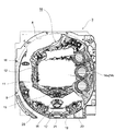
図3と図4に示すように、前記可動役物装置13は、装飾ケース12の裏面にネジ止め等により固定された合成樹脂製の支持ベース22と、この支持ベース22に後述する3個のローラを介して回転可能に支持されたリング状の回転板23とを備えている。図5に示すように、支持ベース22の中央部には装飾ケース12の貫通孔11とほぼ同じ大きさの透孔22aが開設されており、可変表示装置14の表示画面14aはこの透孔22a内に露出している。支持ベース22の下辺中央部には落下防止片24が一体形成されており、この落下防止片24の斜め上方には一対のフォトインタラプタ25,26が実装されている。落下防止片24は回転板23の回転中心Oを通る垂線L上に位置しており、支持ベース22の上辺中央部にはこの垂線Lを介して対向する一対のストッパ突起27,28が設けられている。また、支持ベース22の下辺側には駆動モータ29が取り付けられており、この駆動モータ29の近傍には減速ギア列30が配設されている。減速ギア列30は駆動モータ29の出力軸に固着された最初段ギア30aを含む複数のギアによって構成されており、減速ギア列30の最終段ギア30bは落下防止片24の近傍に位置している。さらに、支持ベース22の右側辺部には後述するケーブルガイド31がネジ止め等によって固定されており、このケーブルガイド31には帯状のフラットケーブル32の一端部がコネクタ接続されている。なお、ケーブルガイド31の内壁面と回転板23の外周縁とは弧状空間Sを介して対向しており、フラットケーブル32はこの弧状空間S内にU字状の反転部32aを有した状態で配置されている。   As shown in FIGS. 3 and 4, the movable accessory device 13 includes a support base 22 made of synthetic resin fixed to the back surface of the decorative case 12 by screws or the like, and three later-described support bases 22. And a ring-shaped rotating plate 23 that is rotatably supported by a roller. As shown in FIG. 5, a through hole 22a having the same size as the through hole 11 of the decorative case 12 is formed at the center of the support base 22, and the display screen 14a of the variable display device 14 is formed through the through hole 22a. It is exposed inside. A fall prevention piece 24 is integrally formed at the center of the lower side of the support base 22, and a pair of photo interrupters 25 and 26 are mounted obliquely above the fall prevention piece 24. The fall prevention piece 24 is positioned on a vertical line L that passes through the rotation center O of the rotating plate 23, and a pair of stopper protrusions 27 and 28 that are opposed to each other through the vertical line L are provided at the center of the upper side of the support base 22. ing. A drive motor 29 is attached to the lower side of the support base 22, and a reduction gear train 30 is disposed in the vicinity of the drive motor 29. The reduction gear train 30 is composed of a plurality of gears including a first gear 30 a fixed to the output shaft of the drive motor 29, and the final gear 30 b of the reduction gear train 30 is located in the vicinity of the fall prevention piece 24. Yes. Further, a cable guide 31 to be described later is fixed to the right side portion of the support base 22 by screws or the like, and one end of a strip-shaped flat cable 32 is connected to the cable guide 31 by a connector. The inner wall surface of the cable guide 31 and the outer peripheral edge of the rotating plate 23 are opposed to each other via an arcuate space S, and the flat cable 32 has a U-shaped reversing portion 32a in the arcuate space S. Has been placed.

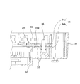
図7と図8に示すように、合成樹脂製の回転板23の中央部には方形状の開口33が開設されており、この開口33を通して可変表示装置14の表示画面14aが目視可能となっている。回転板23の上方部分は小径部23aとなっており、小径部23aとその下方の大径部23bとは左右一対の平坦部23cを介して連続している。また、小径部23aの下方には一対のガイド孔23eが形成されており、これらガイド孔23eは開口33の上辺に沿って左右方向へ延びている。さらに、小径部23aと大径部23bの外周縁には薄肉部23dが形成されており、図3に示すように、この薄肉部23dを3個のローラ34で支持することにより、回転板23は各ローラ34を介して支持ベース22に回転可能に支持されている。これらローラ34は全て後述するダブルローラ構造となっており、以下、このダブルローラ構造について回転板23の左下部を支持するローラ34を例にとって説明する。   As shown in FIGS. 7 and 8, a rectangular opening 33 is formed at the center of the synthetic resin rotating plate 23, and the display screen 14 a of the variable display device 14 can be seen through the opening 33. ing. The upper portion of the rotating plate 23 is a small diameter portion 23a, and the small diameter portion 23a and the large diameter portion 23b below the small diameter portion 23a are continuous via a pair of left and right flat portions 23c. A pair of guide holes 23e are formed below the small diameter portion 23a, and these guide holes 23e extend in the left-right direction along the upper side of the opening 33. Further, a thin portion 23d is formed on the outer peripheral edges of the small diameter portion 23a and the large diameter portion 23b, and the thin plate portion 23d is supported by three rollers 34 as shown in FIG. Is rotatably supported on the support base 22 via each roller 34. All of these rollers 34 have a double roller structure, which will be described later. Hereinafter, this double roller structure will be described by taking as an example a roller 34 that supports the lower left portion of the rotating plate 23.

図6に示すように、回転板23の左下部を支持するローラ34は、回転板23の薄肉部23dを板厚方向に挟持する上側ローラ半体34aと下側ローラ半体34bとからなり、これら上側ローラ半体34aと下側ローラ半体34bは支持ベース22に植設された支軸35に同軸配置され、支軸35を中心に回転可能に支持されている。ただし、薄肉部23dの外周端と上側ローラ半体34aの軸部との間には間隙Slが形成されており、薄肉部23dは上側ローラ半体34aおよび下側ローラ半体34bと径方向では非接触となっている。回転板23の右下部を支持するローラ34も全く同じ構成であり、このようにダブルローラ構造のローラ34によって回転板23の左右両下部を支持すると、径寸法の大きな上側ローラ半体34aと下側ローラ半休34bによって回転板23を確実に支持した上で、回転板23とローラ34間に生じる摩擦抵抗を低減して回転板23をスムーズに回転させることが可能になる。なお、回転板23の中央上部を支持する残りのローラ34も径寸法が幾分小さいだけで同様のダブルローラ構造となっている。ただし、中央上部のローラ34には回転板23の重量が作用しないため、このローラ34については必ずしもダブルローラ構造としなくても良く、一般的なシングルローラ構造のローラを用いることも可能である。   As shown in FIG. 6, the roller 34 that supports the lower left portion of the rotating plate 23 includes an upper roller half 34a and a lower roller half 34b that sandwich the thin portion 23d of the rotating plate 23 in the plate thickness direction. The upper roller half 34 a and the lower roller half 34 b are coaxially arranged on a support shaft 35 planted on the support base 22, and are supported rotatably about the support shaft 35. However, a gap S1 is formed between the outer peripheral end of the thin portion 23d and the shaft portion of the upper roller half 34a, and the thin portion 23d is in the radial direction with respect to the upper roller half 34a and the lower roller half 34b. Contactless. The roller 34 that supports the lower right portion of the rotating plate 23 has the same configuration. When the left and right lower portions of the rotating plate 23 are supported by the roller 34 having the double roller structure, the upper roller half 34a having a large diameter and the lower It is possible to rotate the rotating plate 23 smoothly by reducing the frictional resistance generated between the rotating plate 23 and the roller 34 after the rotating plate 23 is reliably supported by the side roller half-off 34b. The remaining roller 34 that supports the central upper portion of the rotating plate 23 has a similar double roller structure with a slightly smaller diameter. However, since the weight of the rotating plate 23 does not act on the roller 34 at the upper center, the roller 34 does not necessarily have a double roller structure, and a general single roller structure roller can also be used.

図3に示すように、回転板23の表面側の下部外周縁にはリングギア36が取り付けられており、前述した減速ギア列30の最終段ギア30bは回転板23の回転中心Oを通る垂線Lの近傍でリングギア36に噛合している。これにより駆動モータ29の回転が減速ギア列30を介して回転板23に伝達され、これら駆動モータ29と減速ギア列30およびリングギア36によって回転駆動機構が構成されている。本実施形態例の場合、この回転駆動機構によって回転板23が初期位置を基準として正逆両方向(時計方向と反時計方向)へ約45度ずつ回転動作されるようになっている。なお、回転板23の時計方向への回転角度は左側の平坦部23cが一方のストッパ突起27に当接することによって規制され、回転板23の反時計方向への回転角度は右側の平坦部23cが他方のストッパ突起28に当接することによって規制される。また、回転板23の外周縁と前述した落下防止片24とは所定間隔を存して対向しており、落下防止片24が回転板23の回転動作を妨げないようになっている。ただし、回転板23を支持しているローラ34が破損したり、外部からの衝撃等によって回転板23がローラ34から外れた場合、回転板23の外周縁が落下防止片24の上端に当接した時点でそれ以上の動きが規制されるため、回転板23の落下事故を確実に防止することができる。   As shown in FIG. 3, a ring gear 36 is attached to the lower outer peripheral edge on the surface side of the rotating plate 23, and the final gear 30 b of the reduction gear train 30 described above is a perpendicular line passing through the rotation center O of the rotating plate 23. Engage with the ring gear 36 in the vicinity of L. As a result, the rotation of the drive motor 29 is transmitted to the rotating plate 23 via the reduction gear train 30, and the drive motor 29, the reduction gear train 30 and the ring gear 36 constitute a rotation drive mechanism. In the case of this embodiment, the rotary drive mechanism rotates the rotary plate 23 by about 45 degrees in both forward and reverse directions (clockwise and counterclockwise) with reference to the initial position. The rotation angle of the rotating plate 23 in the clockwise direction is regulated by the left flat portion 23c coming into contact with one stopper projection 27, and the rotation angle of the rotating plate 23 in the counterclockwise direction is controlled by the right flat portion 23c. It is regulated by coming into contact with the other stopper projection 28. Further, the outer peripheral edge of the rotating plate 23 and the above-described drop prevention piece 24 are opposed to each other with a predetermined interval, so that the fall prevention piece 24 does not hinder the rotation operation of the rotation plate 23. However, when the roller 34 supporting the rotating plate 23 is damaged or the rotating plate 23 is detached from the roller 34 due to an external impact or the like, the outer peripheral edge of the rotating plate 23 contacts the upper end of the fall prevention piece 24. Since the further movement is restricted at the time, the fall accident of the rotating plate 23 can be surely prevented.

図8に示すように、回転板23の裏面側の外周縁には遮光板37が取り付けられており、この遮光板37には短尺な遮光壁37aと長尺な遮光壁37bが同心円状に立設されている。前述した一対のフォトインタラプタ25,26はこれら遮光壁37a,37bの回転軌跡上に位置しており、両フォトインタラプタ25,26の出力信号に基づいて回転板23の初期位置と回転方向を検出できるようになっている。具体的には、回転板23が初期位置にあるとき、短尺な遮光壁37aは一方のフォトインタラプタ25の光路を横切る位置にあり、長尺な遮光壁37bは他方のフォトインタラプタ26の光路を横切る位置にあるため、両フォトインタラプタ25,26から共にオフ信号が出力される。また、回転板23が初期位置から時計方向へ回転すると、短尺な遮光壁37aは一方のフォトインタラプタ25の光路から外れる位置へ移動し、長尺な遮光壁37bも他方のフォトインタラプタ26の光路から外れる位置へ移動するため、両フォトインタラプタ25,26から共にオン信号が出力される。それとは逆に回転板23が初期位置から反時計方向へ回転すると、短尺な遮光壁37aは一方のフォトインタラプタ25の光路から外れる位置へ移動するが、長尺な遮光壁37bは他方のフォトインタラプタ26の光路内を移動するため、一方のフォトインタラプタ25からオン信号が出力されると共に、他方のフォトインタラプタ26からオフ信号が出力される。   As shown in FIG. 8, a light shielding plate 37 is attached to the outer peripheral edge on the back surface side of the rotating plate 23, and a short light shielding wall 37a and a long light shielding wall 37b stand up concentrically on the light shielding plate 37. It is installed. The pair of photo interrupters 25 and 26 described above are located on the rotation locus of the light shielding walls 37a and 37b, and the initial position and the rotation direction of the rotating plate 23 can be detected based on the output signals of both the photo interrupters 25 and 26. It is like that. Specifically, when the rotating plate 23 is in the initial position, the short light shielding wall 37a is in a position that crosses the optical path of one photo interrupter 25, and the long light shielding wall 37b crosses the optical path of the other photo interrupter 26. Since it is in the position, both of the photo interrupters 25 and 26 output off signals. Further, when the rotating plate 23 rotates clockwise from the initial position, the short light shielding wall 37a moves to a position deviating from the optical path of one photointerrupter 25, and the long light shielding wall 37b also moves from the optical path of the other photointerrupter 26. In order to move to a position that deviates, both of the photo interrupters 25 and 26 output ON signals. On the contrary, when the rotating plate 23 rotates counterclockwise from the initial position, the short light shielding wall 37a moves to a position out of the optical path of one photo interrupter 25, while the long light shielding wall 37b moves to the other photo interrupter. In order to move in the optical path 26, an on signal is output from one photo interrupter 25 and an off signal is output from the other photo interrupter 26.

図3に示すように、回転板23の前面の大部分は合成樹脂製の装飾カバー38によって覆われており、この装飾カバー38には回転板23の開口33と同じ大きさの矩形状の窓孔39が設けられている。図9に示すように、装飾カバー38には窓孔39を上下左右に包囲する周壁38aが一体形成されており、この周壁38aの近傍を含む複数箇所で回転板23と装飾カバー38をネジ止めすることにより、全体として機械的強度の高い回転板23と装飾カバー38の一体品が構成されている。   As shown in FIG. 3, most of the front surface of the rotating plate 23 is covered with a synthetic resin decorative cover 38, and the decorative cover 38 has a rectangular window having the same size as the opening 33 of the rotating plate 23. A hole 39 is provided. As shown in FIG. 9, the decorative cover 38 is integrally formed with a peripheral wall 38a surrounding the window hole 39 vertically and horizontally, and the rotating plate 23 and the decorative cover 38 are screwed at a plurality of locations including the vicinity of the peripheral wall 38a. By doing so, an integrated product of the rotary plate 23 and the decorative cover 38 having a high mechanical strength as a whole is configured.

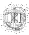
図4に示すように、回転板23の裏面には一対のスライド板40,41が搭載されており、便宜上、回転板23の前方から見て左側に位置するスライド板40を第1スライド板、右側に位置するスライド板41を第2スライド板と呼ぶと、第1スライド板40と第2スライド板41は開口33を介して左右両側で対向している。第1スライド板40と第2スライド板41は扉を模した可動体であり、図示省略されているが、これら両スライド板40,41の内部には複数のLEDが実装されている。また、回転板23の裏面には、第1スライド板40の駆動機構である第1モータ42および第1スクリューシャフト43と、第2スライド板41の駆動機構である第2モータ44および第2スクリューシャフト45がそれぞれ搭載されている。   As shown in FIG. 4, a pair of slide plates 40 and 41 are mounted on the back surface of the rotating plate 23. For convenience, the sliding plate 40 positioned on the left side when viewed from the front of the rotating plate 23 is a first slide plate, When the slide plate 41 located on the right side is called a second slide plate, the first slide plate 40 and the second slide plate 41 are opposed to each other on the left and right sides through the opening 33. The first slide plate 40 and the second slide plate 41 are movable bodies simulating doors and are not shown in the figure, but a plurality of LEDs are mounted inside these slide plates 40 and 41. Further, on the rear surface of the rotating plate 23, a first motor 42 and a first screw shaft 43 that are driving mechanisms of the first slide plate 40, and a second motor 44 and second screw that are driving mechanisms of the second slide plate 41 are provided. Each shaft 45 is mounted.

第1モータ42の出力軸にはピニオン46が固着され、第2モータ44の出力軸にはピニオン47が固着されている。第1モータ42と第2モータ44は回転板23の回転中心Oを通る垂線Lを対称軸とする位置に取り付けられており、図10〜図14に示すように、これら第1モータ42と第2モータ44は互いの反出力軸側を向かい合わせにして近接配置されている。   A pinion 46 is fixed to the output shaft of the first motor 42, and a pinion 47 is fixed to the output shaft of the second motor 44. The first motor 42 and the second motor 44 are attached at positions having a perpendicular line L passing through the rotation center O of the rotating plate 23 as an axis of symmetry. As shown in FIGS. The two motors 44 are arranged close to each other with their opposite output shaft sides facing each other.

第1スクリューシャフト43と第2スクリューシャフト45は開口33の下辺に沿って平行に配置されているが、これら第1スクリューシャフト43と第2スクリューシャフト45は前記垂線Lに直交する同一平面上で前後方向へ位置ずれしており、第1スクリューシャフト43の右側部分と第2スクリューシャフト45の左側部分が前後方向にオーバーラップしている。第1スクリューシャフト43の一端部にはピニオン48が固着されており、このピニオン48と前記ピニオン46を中継ギア49を介して連結することにより、第1モータ42の回転が第1スクリューシャフト43に伝達されるようになっている。また、第2スクリューシャフト45の一端部にはピニオン50が固着されており、このピニオン50と前記ピニオン47を中継ギア51を介して連結することにより、第2モータ44の回転が第2スクリューシャフト45に伝達されるようになっている。すなわち、第1スクリューシャフト43は第1モータ42の出力軸から第2モータ44側に向かって延出し、第2スクリューシャフト45は第2モータ44の出力軸から第1モータ42側に向かつて延出している。   The first screw shaft 43 and the second screw shaft 45 are arranged in parallel along the lower side of the opening 33, and the first screw shaft 43 and the second screw shaft 45 are on the same plane orthogonal to the perpendicular L. The position is shifted in the front-rear direction, and the right side portion of the first screw shaft 43 and the left side portion of the second screw shaft 45 overlap in the front-rear direction. A pinion 48 is fixed to one end portion of the first screw shaft 43, and the rotation of the first motor 42 is connected to the first screw shaft 43 by connecting the pinion 48 and the pinion 46 via a relay gear 49. It is to be transmitted. Further, a pinion 50 is fixed to one end of the second screw shaft 45. By connecting the pinion 50 and the pinion 47 via the relay gear 51, the rotation of the second motor 44 is rotated to the second screw shaft 45. 45 is transmitted. That is, the first screw shaft 43 extends from the output shaft of the first motor 42 toward the second motor 44, and the second screw shaft 45 extends from the output shaft of the second motor 44 toward the first motor 42. I'm out.

第1スライド板40の下端部にはガイド筒体52が取り付けられており、このガイド筒体52は第1スクリューシャフト43に嵌挿されている。ガイド筒体52の内周面には第1スクリューシャフト43の螺旋状溝と係合する突部(図示せず)が形成されており、第1モータ42の回転に伴って第1スライド板40は第1スクリューシャフト43の軸線方向(X1−X2方向)へ往復移動する。また、第1スライド板40の上端部にはL字状に折り曲げられた突起40aが一体形成されており、この突起40aは回転板23に形成された一方のガイド孔23eの上壁と摺動可能に係合している(図9参照)。すなわち、第1モータ42の駆動力は第1スライド板40に対して下端側のみから付与され、上端側は駆動力の付与されない自由端となっており、この自由端側の端面に小さめな磁石53が固着されている。   A guide cylinder 52 is attached to the lower end portion of the first slide plate 40, and the guide cylinder 52 is fitted into the first screw shaft 43. A protrusion (not shown) that engages with the spiral groove of the first screw shaft 43 is formed on the inner peripheral surface of the guide cylinder 52, and the first slide plate 40 is rotated with the rotation of the first motor 42. Reciprocates in the axial direction of the first screw shaft 43 (X1-X2 direction). A protrusion 40a bent in an L shape is integrally formed at the upper end of the first slide plate 40, and this protrusion 40a slides on the upper wall of one guide hole 23e formed in the rotating plate 23. Engageable (see FIG. 9). That is, the driving force of the first motor 42 is applied only to the first slide plate 40 from the lower end side, and the upper end side is a free end to which no driving force is applied, and a small magnet is provided on the end surface on the free end side. 53 is fixed.

同様に、第2スライド板41の下端部にはガイド筒体54が取り付けられており、このガイド筒体54は第2スクリューシャフト45に嵌挿されている。ガイド筒体54の内周面には第2スクリューシャフト45の螺旋状溝と係合する突部(図示せず)が形成されており、第2モータ44の回転に伴って第2スライド板41は第2スクリューシャフト45の軸線方向(X1−X2方向)へ往復移動する。また、第2スライド板41の上端部にはL字状に折り曲げられた突起41aが一体形成されており、この突起40aは回転板23に形成された他方のガイド孔23eの上壁と摺動可能に係合している。すなわち、第2モータ44の駆動力は第2スライド板41に対して下端側のみから付与され、上端側は駆動力の付与されない自由端となっており、この自由端側の端面に鉄板等からなる磁性体55が取り付けられている。   Similarly, a guide cylinder 54 is attached to the lower end portion of the second slide plate 41, and the guide cylinder 54 is fitted into the second screw shaft 45. A protrusion (not shown) that engages with the spiral groove of the second screw shaft 45 is formed on the inner peripheral surface of the guide cylinder 54, and the second slide plate 41 is rotated with the rotation of the second motor 44. Reciprocates in the axial direction (X1-X2 direction) of the second screw shaft 45. A protrusion 41a bent in an L shape is integrally formed at the upper end of the second slide plate 41, and this protrusion 40a slides on the upper wall of the other guide hole 23e formed in the rotary plate 23. Engagement possible. That is, the driving force of the second motor 44 is applied only to the second slide plate 41 from the lower end side, and the upper end side is a free end to which no driving force is applied. A magnetic body 55 is attached.

図12に示すように、第1スライド板40と第2スライド板41は通常の遊技状態で最も離反した退避位置にあり、この場合、回転板23の開口33は全開状態となっている。この状態で第1モータ42と第2モータ44をそれぞれ一方向へ回転駆動すると、図13に示すように、第1スライド板40が第1スクリューシャフト43の軸線に沿って矢印X1方向へ移動すると共に、第2スライド板41が第2スクリューシャフト45の軸線に沿って矢印X2方向へ移動するため、第1スライド板40と第2スライド板41の対向間距離が次第に狭まっていく。さらに第1モータ42と第2モータ44の回転を続行すると、図14に示すように、第1スライド板40と第2スライド板41が互いの対向面を当接させた近接位置まで移動し、開口33の中央部を含む大部分が第1スライド板40と第2スライド板41によって遮蔽された近接状態となる。   As shown in FIG. 12, the first slide plate 40 and the second slide plate 41 are in the retreat positions that are most separated in the normal gaming state, and in this case, the opening 33 of the rotating plate 23 is fully opened. When the first motor 42 and the second motor 44 are each driven to rotate in one direction in this state, the first slide plate 40 moves in the arrow X1 direction along the axis of the first screw shaft 43 as shown in FIG. At the same time, since the second slide plate 41 moves in the direction of the arrow X2 along the axis of the second screw shaft 45, the distance between the first slide plate 40 and the second slide plate 41 gradually decreases. When the rotation of the first motor 42 and the second motor 44 is further continued, as shown in FIG. 14, the first slide plate 40 and the second slide plate 41 move to a close position where the opposing surfaces abut each other, A large part including the central portion of the opening 33 is in the proximity state shielded by the first slide plate 40 and the second slide plate 41.

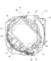
ここで、本実施形態例では、第1スライド板40と第2スライド板41の対向間距離を意図的に変えてあり、両スライド板40,41は、両スライド板40,41の自由端(上端)側の対向間距離に対して駆動端(下端)側の対向間距離が広くなるような姿勢(初期姿勢)に予め設定してある。このため、図15に示すように、第1スライド板40と第2スライド板41の自由端側のコーナ部同士が当接したとき、駆動端側のコーナ部同士はまだ当接しておらず、第1スライド板40と第2スライド板41の対向面間に駆動端側を底辺とする三角形状の隙間S2が形成される。この状態から第1モータ42と第2モータ44の回転を続行すると、第1スライド板40と第2スライド板41は自由端側を当接したまま隙間S2の底辺を狭めるように移動し、第1スライド板40と第2スライド板41の駆動端側のコーナ部同士が当接した時点で第1モータ42と第2モータ44の回転は停止される。その結果、図16に示すように、第1スライド板40と第2スライド板41の対向面同士が自由端側から駆動端側に至る全ての部分で当接し、開口33内に臨む可変表示装置14の表示画面14aが第1スライド板40と第2スライド板41によって確実に遮蔽される。 Here, in the present embodiment, the distance between the first slide plate 40 and the second slide plate 41 is intentionally changed, and both the slide plates 40 and 41 are free ends of the slide plates 40 and 41 ( The posture (initial posture) is set in advance such that the distance between the opposing ends on the drive end (lower end) side becomes larger than the distance between the opposing ends on the upper end) side. For this reason, as shown in FIG. 15, when the corner portions on the free end side of the first slide plate 40 and the second slide plate 41 are in contact with each other, the corner portions on the drive end side are not yet in contact with each other, A triangular gap S <b> 2 is formed between the opposing surfaces of the first slide plate 40 and the second slide plate 41 with the drive end side as the base. When the rotation of the first motor 42 and the second motor 44 is continued from this state, the first slide plate 40 and the second slide plate 41 move so as to narrow the bottom of the gap S2 while keeping the free end side in contact, The rotations of the first motor 42 and the second motor 44 are stopped when the corners on the driving end side of the first slide plate 40 and the second slide plate 41 come into contact with each other. As a result, as shown in FIG. 16, the variable display device in which the opposing surfaces of the first slide plate 40 and the second slide plate 41 are in contact with each other from the free end side to the drive end side and face the opening 33. 14 display screens 14 a are reliably shielded by the first slide plate 40 and the second slide plate 41.

図17と図18に示すように、前記ケーブルガイド31は後部ケース31aと前部ケース31bで構成されており、これら両ケース31a,31bは接合・一体化された状態で支持ベース22に固定されている。ケーブルガイド31の内部には回路基板56が収納されており、この回路基板56は遊技盤3の裏面側に配設された図示せぬ制御基板と接続されている。また、回路基板56には2つの固定側コネクタ57が実装されており、これら固定側コネクタ57に2枚のフラットケーブル32の一端部が接続されていると共に、両フラットケーブル32の他端部が回転板23の外周部に取り付けた可動側コネクタ58に接続されている(図3参照)。したがって、正逆両方向へ回転する回転板23に搭載された両モータ42,44や両スライド板40,41内のLED等の電気部品に対し、その回転角度に拘わらず前記制御基板からの制御信号をフラットケーブル32を介して確実に伝送することができる。なお、2枚のフラットケーブル32は固定側コネクタ57との接続部分を除くと密着状態で重ねられており、外観上は1枚のフラットケーブルと大差ないため、以下、2枚のフラットケーブル32を1枚のものとして説明することとする。   As shown in FIGS. 17 and 18, the cable guide 31 is composed of a rear case 31a and a front case 31b. These cases 31a and 31b are fixed to the support base 22 in a joined and integrated state. ing. A circuit board 56 is housed inside the cable guide 31, and this circuit board 56 is connected to a control board (not shown) disposed on the back side of the game board 3. In addition, two fixed-side connectors 57 are mounted on the circuit board 56, and one end portions of the two flat cables 32 are connected to the fixed-side connector 57, and the other end portions of the two flat cables 32 are connected to each other. It is connected to a movable connector 58 attached to the outer periphery of the rotating plate 23 (see FIG. 3). Therefore, the control signals from the control board are applied to the electric components such as the motors 42 and 44 mounted on the rotating plate 23 rotating in both the forward and reverse directions and the LEDs in the slide plates 40 and 41 regardless of the rotation angle. Can be reliably transmitted via the flat cable 32. The two flat cables 32 are stacked in close contact except for the connection portion with the fixed connector 57. Since the appearance is not much different from one flat cable, the two flat cables 32 will be referred to below. It will be described as a single sheet.

ケーブルガイド31の弧状空間Sに対向する内壁面は湾曲面形状となっており、この内壁面の上端部から下端部に至る全域にはガイド溝59が形成されている。ガイド溝59の中央部のやや下方位置には導出口60が形成されており、ケーブルガイド31の内部で固定側コネクタ57に接続されたフラットケーブル32は、導出口60から下方へ向かって導出された後、反転部32aで上方へ方向転換して回転板23の可動側コネクタ58に接続されている。ガイド溝59は導出口60から導出されたフラットケーブル32を幅方向に位置規制する機能を有し、その幅寸法はガイド溝59の延出方向の全域で同一に設定されているが、深さ寸法はガイド溝59の延出方向で部分的に変えてある。具体的には、ガイド溝59の深さ寸法を導出口60から下方に向かって漸次大きくし、ガイド溝59の下端部上方の最深位置59aで最大の深さd1となるように設定されている。なお、導出口60からガイド溝59の上端部に至る部分は延長ガイド部59bとなっており、この延長ガイド部59bの溝深さは導出口60の近傍と同じ最小深さd2に設定されている。   The inner wall surface facing the arcuate space S of the cable guide 31 has a curved surface shape, and a guide groove 59 is formed in the entire region from the upper end portion to the lower end portion of the inner wall surface. A guide port 60 is formed at a position slightly below the center of the guide groove 59, and the flat cable 32 connected to the fixed connector 57 inside the cable guide 31 is led out downward from the guide port 60. After that, the direction is changed upward by the reversing part 32 a and connected to the movable connector 58 of the rotating plate 23. The guide groove 59 has a function of regulating the position of the flat cable 32 led out from the lead-out port 60 in the width direction, and the width dimension is set to be the same throughout the extending direction of the guide groove 59. The dimensions are partially changed in the extending direction of the guide groove 59. Specifically, the depth dimension of the guide groove 59 is gradually increased downward from the outlet 60, and is set to have the maximum depth d1 at the deepest position 59a above the lower end of the guide groove 59. . A portion from the outlet 60 to the upper end of the guide groove 59 is an extension guide 59b. The groove depth of the extension guide 59b is set to the same minimum depth d2 as the vicinity of the outlet 60. Yes.

ガイド溝59とフラットケーブル32の反転部32aとの相対位置は回転板23の回転角度に応じて変化するが、回転板23が初期位置にあるとき、反転部32aは図18の実線で示すようにガイド溝59の最深位置59aの近傍に位置している。この場合、ガイド溝59の溝底面と回転板23の外周縁間の距離(弧状空間Sの幅寸法)は最深位置59aで最大となるため、反転部32aの曲率半径を十分に大きく保つことができ、それによってフラットケーブル32に掛かる曲げ応力が低減されている。また、回転板23が初期位置から時計方向に回転すると、図18の2点鎖線で示すように、反転部32aはガイド溝59の下端部から突出する位置まで変位するが、導出口60から導出されて反転部32aに至る部分のフラットケーブル32がガイド溝59によって幅方向に位置規制されているため、ガイド溝59から突出した反転部32aが周囲の部材にぶつかって損傷するこはない。これとは逆に回転板23が初期位置から反時計方向に回転すると、図18の破線で示すように、反転部32aはガイド溝59の最深位置59aから離れて導出口60の近傍まで移動するが、この場合は導出口60の存在によって反転部32aの曲率半径が大きく保たれるため、フラットケーブル32に掛かる曲げ応力は低減されている。しかも、ガイド溝59の溝深さが導出口60から最深位置59aに向かって漸次大きくなるように設定されているため、反時計方向の末端位置まで回転した回転板23を初期位置に戻すとき、反転部32aをガイド溝59内でスムーズに移動させて最深位置59aの近傍まで導くことができる。   The relative position between the guide groove 59 and the reversing portion 32a of the flat cable 32 varies depending on the rotation angle of the rotating plate 23. When the rotating plate 23 is at the initial position, the reversing portion 32a is indicated by a solid line in FIG. The guide groove 59 is located in the vicinity of the deepest position 59a. In this case, the distance between the groove bottom surface of the guide groove 59 and the outer peripheral edge of the rotating plate 23 (the width dimension of the arcuate space S) becomes maximum at the deepest position 59a, so that the radius of curvature of the reversing portion 32a can be kept sufficiently large. This reduces the bending stress on the flat cable 32. When the rotating plate 23 rotates clockwise from the initial position, the reversing portion 32a is displaced to a position protruding from the lower end portion of the guide groove 59 as shown by a two-dot chain line in FIG. Since the portion of the flat cable 32 reaching the reversing portion 32a is regulated in the width direction by the guide groove 59, the reversing portion 32a protruding from the guide groove 59 does not collide with surrounding members and be damaged. On the contrary, when the rotating plate 23 rotates counterclockwise from the initial position, the reversing portion 32a moves away from the deepest position 59a of the guide groove 59 to the vicinity of the outlet 60 as shown by the broken line in FIG. However, in this case, the bending radius applied to the flat cable 32 is reduced because the radius of curvature of the reversing portion 32a is kept large by the presence of the outlet 60. Moreover, since the groove depth of the guide groove 59 is set so as to gradually increase from the outlet 60 toward the deepest position 59a, when the rotating plate 23 rotated to the end position in the counterclockwise direction is returned to the initial position, The reversing part 32a can be smoothly moved in the guide groove 59 and guided to the vicinity of the deepest position 59a.

次に、このように構成された可動役物装置13の動作を主に図19〜図21を参照して説明する。なお、図19〜図21は可動役物装置13を遊技盤3の正面側から見た動作説明図であり、回転板23に搭載された両スライド板40,41やその駆動装置である両モータ42,44および両スクリューシャフト43,45は図示省略してある。   Next, the operation of the movable accessory device 13 configured as described above will be described mainly with reference to FIGS. 19 to 21 are operation explanatory views of the movable accessory device 13 as viewed from the front side of the game board 3, and both the slide plates 40 and 41 mounted on the rotating plate 23 and the both motors which are driving devices thereof. 42 and 44 and both screw shafts 43 and 45 are not shown.

本実施形態例に係る可動役物装置13では、通常の遊技状態において回転板23は図19に示す初期位置にあり、この初期位置で回転板23の開口33は装飾ケース12の貫通孔11と一致する横長形状に保たれている。この場合、第1スライド板40と第2スライド板41は開口33の左右両側に隠れた退避位置にあり、可変表示装置14の表示画面14aは支持ベース22の透孔22aを通して開口33内に露出している。また、回転板23の外周部に取り付けられた可動側コネクタ58は弧状空間Sを介してケーブルガイド31の中央部分と対向しており、可動側コネクタ58に接続されたフラットケーブル32の反転部32aはケーブルガイド31の内壁面に形成されたガイド溝59の最深位置59aの近傍に位置している。   In the movable accessory device 13 according to the present embodiment example, the rotating plate 23 is in the initial position shown in FIG. 19 in a normal gaming state, and the opening 33 of the rotating plate 23 and the through hole 11 of the decorative case 12 are in this initial position. It is kept in a matching landscape shape. In this case, the first slide plate 40 and the second slide plate 41 are in the retracted positions hidden on the left and right sides of the opening 33, and the display screen 14 a of the variable display device 14 is exposed in the opening 33 through the through hole 22 a of the support base 22. doing. In addition, the movable connector 58 attached to the outer peripheral portion of the rotating plate 23 faces the central portion of the cable guide 31 through the arc space S, and the reversing portion 32 a of the flat cable 32 connected to the movable connector 58. Is located in the vicinity of the deepest position 59 a of the guide groove 59 formed on the inner wall surface of the cable guide 31.

この状態で駆動モータ29を正逆いずれか一方へ回転駆動すると、駆動モータ29の回転が減速ギア列30からリングギア36を介して回転板23に伝達されるため、回転板23が初期位置から時計方向へ回転する。そして、回転板23が初期位置から時計方向へ約45度まで回転すると、図20に示すように、回転板23の左側の平坦部23cが一方のストッパ突起27に当接し、当該位置で駆動モータ29を駆動停止して回転板23の回転を停止させる。その結果、開口33が表示画面14aに対して斜め45度の右下がり状態となり、回転板23の前面に配設された装飾カバー38の一部が装飾ケース12の貫通孔11から露出する。また、かかる回転板23の回転に伴って可動側コネクタ58がケーブルガイド31の下端部付近まで移動し、それに追従してフラットケーブル32の反転部32aがガイド溝59の最深位置59aから下方へ移動するため、可動側コネクタ58からケーブルガイド31の下端部に至る部分のフラットケーブル32が曲率半径の大きな反転部32aとなる。   When the drive motor 29 is rotationally driven in either of the forward and reverse directions in this state, the rotation of the drive motor 29 is transmitted from the reduction gear train 30 to the rotary plate 23 via the ring gear 36, so that the rotary plate 23 is moved from the initial position. Rotate clockwise. Then, when the rotating plate 23 is rotated clockwise by about 45 degrees from the initial position, as shown in FIG. 20, the flat portion 23c on the left side of the rotating plate 23 comes into contact with one stopper projection 27, and the drive motor is at that position. 29 is stopped to stop the rotation of the rotating plate 23. As a result, the opening 33 is inclined 45 degrees to the right with respect to the display screen 14 a, and a part of the decorative cover 38 disposed on the front surface of the rotating plate 23 is exposed from the through hole 11 of the decorative case 12. As the rotating plate 23 rotates, the movable connector 58 moves to the vicinity of the lower end of the cable guide 31, and the reversing portion 32 a of the flat cable 32 moves downward from the deepest position 59 a of the guide groove 59. Therefore, the portion of the flat cable 32 extending from the movable connector 58 to the lower end portion of the cable guide 31 becomes the reversing portion 32a having a large curvature radius.

一方、回転板23が初期位置にある状態で駆動モータ29を他方へ回転駆動すると、回転板23が初期位置から反時計方向へ回転する。そして、回転板23が初期位置から反時計方向へ約45度まで回転すると、図21に示すように、回転板23の右側の平坦部23cが他方のストッパ突起28に当接し、当該位置で駆動モータ29を駆動停止して回転板23の回転を停止させる。その結果、開口33が表示画面14aに対して斜め45度の左下がり状態となり、装飾カバー38の一部が装飾ケース12の貫通孔11から露出する。また、かかる回転板23の回転に伴って可動側コネクタ58がケーブルガイド31の上端部付近まで移動し、それに追従してフラットケーブル32の反転部32aがガイド溝59の最深位置59aから導出口60の近傍まで移動するため、導出口60から導出されたフラットケーブル32は延長ガイド部59bに対面する弧状空間Sを通って可動側コネクタ58まで至る。この場合、導出口60の側方に位置する弧状空間Sの幅寸法は最深位置59aの形成箇所に比べて狭くなるが、ガイド溝59の溝底面を切り欠いて形成した導出口60の存在によって反転部32aの曲率半径が大きく保たれるため、フラットケーブル32に掛かる曲げ応力は低減される。しかも、回転板23はほとんどの場合に初期位置に保たれており、回転板23が図21に示す位置まで回転する頻度は非常に少ないため、回転板23の回転途中で反転部32aの曲率半径が一時的に小さくなったとしても、それによってフラットケーブル32が損傷する虞はない。   On the other hand, when the drive motor 29 is rotationally driven to the other side with the rotary plate 23 in the initial position, the rotary plate 23 rotates counterclockwise from the initial position. When the rotating plate 23 rotates counterclockwise from the initial position to about 45 degrees, as shown in FIG. 21, the flat portion 23c on the right side of the rotating plate 23 comes into contact with the other stopper projection 28 and is driven at that position. The driving of the motor 29 is stopped and the rotation of the rotating plate 23 is stopped. As a result, the opening 33 is inclined 45 degrees to the left with respect to the display screen 14 a, and a part of the decorative cover 38 is exposed from the through hole 11 of the decorative case 12. Further, as the rotating plate 23 rotates, the movable connector 58 moves to the vicinity of the upper end portion of the cable guide 31, and the reversing portion 32 a of the flat cable 32 follows the lead port 60 from the deepest position 59 a of the guide groove 59. Therefore, the flat cable 32 led out from the lead-out port 60 reaches the movable connector 58 through the arcuate space S facing the extension guide portion 59b. In this case, although the width dimension of the arc-shaped space S located on the side of the outlet 60 is narrower than that of the deepest position 59a, the presence of the outlet 60 formed by cutting out the groove bottom surface of the guide groove 59 is provided. Since the curvature radius of the reversing part 32a is kept large, the bending stress applied to the flat cable 32 is reduced. In addition, the rotating plate 23 is maintained at the initial position in most cases, and the frequency of the rotating plate 23 rotating to the position shown in FIG. Even if it becomes temporarily small, there is no possibility that the flat cable 32 may be damaged thereby.

また、このように回転板23が初期位置を含めて任意の回転位置にあるとき、前述した第1スライド板40と第2スライド板41の開閉動作を行わせることにより、両スライド板40,41の開閉方向と可変表示装置14の表示内容とを関連付けたインパクトのある演出を実現することができる。例えば、通常のリーチ時に回転板23を初期位置に保ったまま両スライド板40,41を表示画面14aに対して水平方向へ往復移動させたり、スーパーリーチ時に回転板23を時計方向または反時計方向へ回転させ、その回転途中や回転末端位置で両スライド板40,41を表示画面14aに対して斜め方向へ往復移動させれば、両スライド板40,41の開閉動作と開閉方向に応じて大当たりの可能性の程度を遊技者に示唆させることができる。   Further, when the rotary plate 23 is in an arbitrary rotational position including the initial position in this way, the slide plates 40 and 41 are opened and closed by performing the opening and closing operations of the first slide plate 40 and the second slide plate 41 described above. It is possible to realize an effect with an impact that associates the opening / closing direction of the image and the display content of the variable display device 14. For example, both slide plates 40 and 41 are reciprocated horizontally with respect to the display screen 14a while keeping the rotating plate 23 at the initial position during normal reach, or the rotating plate 23 is rotated clockwise or counterclockwise during super reach. If the slide plates 40, 41 are reciprocated in the oblique direction with respect to the display screen 14a during the rotation or at the rotation end position, the jackpot is made according to the opening / closing operation and the opening / closing direction of the slide plates 40, 41. It is possible to make the player suggest the degree of possibility.

以上説明したように、本実施形態例に係る可動役物装置13では、可変表示装置14の周囲に一対のスライド板40,41とその駆動装置である一対のモータ42,44を配置し、これらモータ42,44から対応するスライド板40,41に対して下端側のみから駆動力が付与されるようになすと共に、スライド板40,41の対向間距離を駆動力の付与されない自由端(上端)側に対して駆動力の付与される駆動端(下端)側が広くなるように設定し、一対のスライド板40,41がそれぞれモータ42,44からの駆動力を受けて近接方向へ移動するとき、自由端側のコーナ部同士が当接した後も両スライド板40,41の移動を続行し、駆動端側のコーナ部同士が当接した位置で両スライド板40,41の移動を停止するようにしてある。すなわち、一対のスライド板40,41の対向間距離を自由端側よりも駆動端側が広くなるように意図的に変えてあり、両スライド板40,41の自由端側のコーナ部同士が当接したとき、両スライド板40,41の対向面間に駆動端側を底辺とする三角形状の隙間S2が形成され、この隙間S2が両スライド板40,41のさらなる移動(オーバーストローク)に伴って狭められるようになっている。したがって、モータ42,44の駆動が停止した時点で、両スライド板40,41は自由端側から駆動端側に至る全ての対向面同士を密着させた状態で停止し、大型化された可変表示装置14の表示画面14aを一対のスライド板40,41によって確実に遮蔽することができる。   As described above, in the movable accessory device 13 according to this embodiment, the pair of slide plates 40 and 41 and the pair of motors 42 and 44 that are driving devices thereof are arranged around the variable display device 14. The driving force is applied only from the lower end side to the corresponding slide plates 40 and 41 from the motors 42 and 44, and the distance between the opposed surfaces of the slide plates 40 and 41 is a free end (upper end) where no driving force is applied. When the driving end (lower end) side to which the driving force is applied is set to be wider with respect to the side, and the pair of slide plates 40 and 41 receive the driving force from the motors 42 and 44, respectively, and move in the proximity direction, The slide plates 40 and 41 continue to move even after the free end corners come into contact with each other, and the movement of the slide plates 40 and 41 stops at the position where the drive end side corners come into contact with each other. In That. That is, the distance between the pair of slide plates 40 and 41 is intentionally changed so that the drive end side is wider than the free end side, and the corner portions on the free end sides of both slide plates 40 and 41 are in contact with each other. When this is done, a triangular gap S2 with the drive end side as the base is formed between the opposing surfaces of both slide plates 40, 41, and this gap S2 is associated with further movement (overstroke) of both slide plates 40, 41. It is designed to be narrowed. Therefore, when the driving of the motors 42 and 44 is stopped, the slide plates 40 and 41 are stopped in a state where all the opposing surfaces from the free end side to the driving end side are in close contact with each other, and the variable display is enlarged. The display screen 14 a of the device 14 can be reliably shielded by the pair of slide plates 40 and 41.

また、モータ42,44の回転をスライド板40,41の直線運動に変換するスクリューシャフト43,45を備えており、これらモータ42,44やスクリューシャフト43,45が搭載された回転板(基体)23に直線状のガイド孔23eを形成し、スライド板40,41の自由端に形成した突起40a,41aをこのガイド孔23eに摺動可能に係合させたので、スライド板40,41がスクリューシャフト43,45の回転方向へ供回りすることが突起40a,41aとガイド孔23eの係合によって防止され、スライド板40,41をスクリューシャフト43,45の軸線方向へスムーズに往復移動させることができる。   In addition, screw shafts 43 and 45 for converting rotation of the motors 42 and 44 into linear motion of the slide plates 40 and 41 are provided, and a rotary plate (base) on which the motors 42 and 44 and the screw shafts 43 and 45 are mounted. 23, linear guide holes 23e are formed, and projections 40a and 41a formed at the free ends of the slide plates 40 and 41 are slidably engaged with the guide holes 23e. The rotation of the shafts 43 and 45 is prevented from engaging with the projections 40a and 41a and the guide holes 23e, and the slide plates 40 and 41 can be smoothly reciprocated in the axial direction of the screw shafts 43 and 45. it can.

また、一方のスライド板40の自由端側に磁石53を固着すると共に、他方のスライド板41の自由端側に磁性体55を固着し、両スライド板40,41の近接位置で磁性体55が磁石53に吸着されるようにしたので、自由端側のコーナ部同士の当接が磁石53の吸引力によってアシストされ、両スライド板40,41の対向面同士を確実に当接させることができる。ただし、このような磁石53と磁性体55を省略したとしても、両スライド板40,41の対向面同士を隙間なく密着させることは可能である。   In addition, the magnet 53 is fixed to the free end side of one slide plate 40, and the magnetic body 55 is fixed to the free end side of the other slide plate 41. Since the magnet 53 is attracted, the contact between the corners on the free end side is assisted by the attractive force of the magnet 53, and the opposing surfaces of the slide plates 40 and 41 can be reliably brought into contact with each other. . However, even if the magnet 53 and the magnetic body 55 are omitted, the facing surfaces of the slide plates 40 and 41 can be brought into close contact with each other without a gap.

また、一対のスライド板40,41や一対のモータ42,44を回転板23に搭載し、この回転板23に可変表示装置14の表示画面14aを目視可能な矩形状の開口33を設けると共に、駆動モータ29や減速ギア列30で構成された回転駆動機構によって回転板23を遊技盤3の盤面と略平行な面内で正逆両方向へ回転させるようにしたので、回転板23の回転に伴って開口33と表示画面14aの相対角度が変化するだけでなく、このように表示画面14aとの相対角度を変化させる開口33内に一対のスライド板40,41が出入するという、これまでにない斬新でインパクトのある演出を実現することができる。この場合、回転板23が初期位置から任意角度へ回転すると、それに伴って両スライド板40,41が水平姿勢から傾斜姿勢へと変化するが、回転板23の回転角度に拘わらず両スライド板40,41の対向面同士を隙間なく密着させることができる。   In addition, a pair of slide plates 40 and 41 and a pair of motors 42 and 44 are mounted on the rotating plate 23, and the rotating plate 23 is provided with a rectangular opening 33 through which the display screen 14 a of the variable display device 14 can be seen. Since the rotary plate 23 is rotated in both forward and reverse directions within a plane substantially parallel to the board surface of the game board 3 by the rotary drive mechanism constituted by the drive motor 29 and the reduction gear train 30, as the rotary plate 23 rotates. Thus, not only has the relative angle between the opening 33 and the display screen 14a changed, but also a pair of slide plates 40 and 41 has entered and exited into the opening 33 that changes the relative angle with the display screen 14a. A novel and impactful production can be realized. In this case, when the rotating plate 23 is rotated from the initial position to an arbitrary angle, both the slide plates 40 and 41 change from the horizontal posture to the inclined posture, but both the slide plates 40 are irrespective of the rotation angle of the rotating plate 23. , 41 can be brought into close contact with each other without a gap.

なお、上記実施形態例では、開口33が設けられた回転板23にスライド板40,41やモータ42,44を搭載し、この回転板23を回転駆動機構によって正逆両方向へ回転させるようにした可動役物装置13について説明したが、回転板23や回転駆動機構は省略することも可能であり、要は、一対のスライド板40,41が可変表示装置14の表示画面14aの前方を近接および離反する方向へ移動可能であれば良い。   In the embodiment described above, the slide plates 40 and 41 and the motors 42 and 44 are mounted on the rotary plate 23 provided with the opening 33, and the rotary plate 23 is rotated in both forward and reverse directions by the rotary drive mechanism. Although the movable accessory device 13 has been described, the rotating plate 23 and the rotation driving mechanism may be omitted. In short, the pair of slide plates 40 and 41 are arranged in the vicinity of the front of the display screen 14a of the variable display device 14 and What is necessary is just to be able to move in the direction to separate.

3 遊技盤
9 遊技領域
10 中央役物ユニット
11 貫通孔
12 装飾ケース
13 可動役物装置
14 可変表示装置
14a 表示画面
22 支持ベース
22a 透孔
23 回転板(基体)
23e ガイド孔(ガイド部)
29 駆動モータ
30 減速ギア列
33 開口
34 ローラ
36 リングギア
38 装飾カバー
39 窓孔
40 第1スライド板
40a 突起
41 第2スライド板
41a 突起
42 第1モータ
43 第1スクリューシャフト
44 第2モータ
45 第2スクリューシャフト
52,54 ガイド筒体
53 磁石
55 磁性体
S2 隙間
DESCRIPTION OF SYMBOLS 3 Game board 9 Game area 10 Central accessory unit 11 Through-hole 12 Decoration case 13 Movable accessory apparatus 14 Variable display apparatus 14a Display screen 22 Support base 22a Through-hole 23 Rotating plate (base | substrate)
23e Guide hole (guide part)
29 drive motor 30 reduction gear train 33 opening 34 roller 36 ring gear 38 decorative cover 39 window hole 40 first slide plate 40a projection 41 second slide plate 41a projection 42 first motor 43 first screw shaft 44 second motor 45 second Screw shaft 52, 54 Guide cylinder 53 Magnet 55 Magnetic body S2 Clearance

Claims (4)

遊技盤の遊技領域に設けられた可変表示装置と、この可変表示装置の表示画面の前方を近接および離反する方向へ移動可能な一対のスライド板と、これらスライド板を一方端側から駆動力を付与して個別に移動させる一対の駆動装置とを備え、一対の前記スライド板の他方端側を駆動力の付与されない自由端側として構成した可動役物装置において、
一対の前記スライド板は、互いに最も離反する退避位置で、前記自由端側の対向間距離に対して前記駆動力の付与される駆動端側の対向間距離が広くなる初期姿勢に設定されており、
前記駆動力によって一対の前記スライド板を前記退避位置から近接方向へ移動するとき、前記自由端側のコーナ部同士が当接するまで前記初期姿勢を維持したまま一対の前記スライド板の移動を続行し前記自由端側のコーナ部同士が当接した後も前記駆動力によって一対の前記スライド板の移動をさらに続行し、前記駆動端側のコーナ部同士が当接した位置で一対の前記スライド板の移動を停止して、一対の前記スライド板の対向面同士を接触させた状態にするようにしたことを特徴とする可動役物装置。
A variable display device provided in the game area of the game board, a pair of slide plates that can move in the direction of approaching and moving away from the front of the display screen of the variable display device, and driving force from one end side of these slide plates In a movable accessory device comprising a pair of drive devices that are individually moved and provided, and the other end side of the pair of slide plates is configured as a free end side to which no drive force is applied,
The pair of slide plates is set to an initial posture in which the distance between the opposing ends on the driving end side to which the driving force is applied is larger than the distance between the opposing ends on the free end side at a retracted position that is most separated from each other. ,
When the pair of slide plates are moved in the proximity direction from the retracted position by the driving force, the movement of the pair of slide plates is continued while maintaining the initial posture until the corner portions on the free end side come into contact with each other. the further continues the movement of the pair of the slide plate by the driving force after the corner portions of the free end side is in contact with the pair of the slide plate at a position where the corner portions of the driving end is in contact with The movable accessory device is characterized in that the movement of the pair is stopped and the opposed surfaces of the pair of slide plates are brought into contact with each other .
請求項1の記載において、前記駆動装置が、前記スライド板を軸線方向へ往復移動させるスクリューシャフトと、このスクリューシャフトを正逆両方向へ回転させるモータとを備え、前記スライド板の前記駆動端側に前記スクリューシャフトに嵌挿されるガイド筒体を設け、前記モータが搭載された基体に前記スクリューシャフトの軸線方向へ延びるガイド部を形成し、このガイド部に一対の前記スライド板の自由端側を摺動可能に係合させたことを特徴とする可動役物装置。 2. The drive device according to claim 1, comprising: a screw shaft that reciprocally moves the slide plate in an axial direction; and a motor that rotates the screw shaft in both forward and reverse directions, on the drive end side of the slide plate. A guide cylinder is provided to be inserted into the screw shaft, a guide portion extending in the axial direction of the screw shaft is formed on the base on which the motor is mounted, and the free end sides of the pair of slide plates are slid on the guide portion. A movable accessory device characterized by being movably engaged. 請求項1の記載において、一対の前記スライド板のいずれか一方の前記自由端側に磁石が固着されると共に、他方の前記自由端側に前記磁石に吸着可能な磁性体が固着されていることを特徴とする可動役物装置。 In apparatus according to claim 1, the magnet is secured to one of said free end of the pair of the slide plate, the adsorbable magnetic material the magnets to the other of the free end side is fixed A movable accessory device characterized by. 請求項の記載において、前記基体である回転板と、この回転板を前記遊技盤の盤面と略平行な面内で正逆両方向へ回転させる回転駆動機構とを備え、前記回転板に前記可変表示装置の表示画面を目視可能な矩形状の開口が設けられ、一対の前記駆動装置が前記回転板に搭載されていると共に、一対の前記スライド板が前記開口を介して前記回転板に対向配置されていることを特徴とする可動役物装置。 3. The rotary plate according to claim 2 , further comprising: a rotary plate that is the base body; and a rotary drive mechanism that rotates the rotary plate in both forward and reverse directions within a plane substantially parallel to the board surface of the game board. A rectangular opening through which a display screen of the display device can be viewed is provided, a pair of the driving devices are mounted on the rotating plate, and a pair of the sliding plates are arranged to face the rotating plate through the opening. A movable accessory device characterized by being made.
JP2009221103A 2009-09-25 2009-09-25 Movable accessory device Expired - Fee Related JP5536404B2 (en)

Priority Applications (1)

Application Number Priority Date Filing Date Title
JP2009221103A JP5536404B2 (en) 2009-09-25 2009-09-25 Movable accessory device

Applications Claiming Priority (1)

Application Number Priority Date Filing Date Title
JP2009221103A JP5536404B2 (en) 2009-09-25 2009-09-25 Movable accessory device

Publications (3)

Publication Number Publication Date
JP2011067406A JP2011067406A (en) 2011-04-07
JP2011067406A5 JP2011067406A5 (en) 2012-08-30
JP5536404B2 true JP5536404B2 (en) 2014-07-02

Family

ID=44013331

Family Applications (1)

Application Number Title Priority Date Filing Date
JP2009221103A Expired - Fee Related JP5536404B2 (en) 2009-09-25 2009-09-25 Movable accessory device

Country Status (1)

Country Link
JP (1) JP5536404B2 (en)

Families Citing this family (4)

* Cited by examiner, † Cited by third party
Publication number Priority date Publication date Assignee Title
JP5043149B2 (en) * 2010-04-21 2012-10-10 株式会社藤商事 Game machine
JP5931029B2 (en) * 2013-09-05 2016-06-08 京楽産業.株式会社 Game machine
JP6306984B2 (en) * 2014-08-26 2018-04-04 株式会社ニューギン Game machine
JP2017006311A (en) * 2015-06-19 2017-01-12 株式会社三共 Game machine

Family Cites Families (3)

* Cited by examiner, † Cited by third party
Publication number Priority date Publication date Assignee Title
JP4310489B2 (en) * 2003-06-27 2009-08-12 株式会社ニューギン Auxiliary production device for gaming machines
JP2006223318A (en) * 2005-01-21 2006-08-31 Okumura Yu-Ki Co Ltd Game machine
JP4313350B2 (en) * 2005-09-01 2009-08-12 株式会社藤商事 Game machine

Also Published As

Publication number Publication date
JP2011067406A (en) 2011-04-07

Similar Documents

Publication Publication Date Title
JP5481138B2 (en) Movable accessory device
JP5701580B2 (en) Game machine
JP5540231B2 (en) Movable accessory device
JP5330950B2 (en) Game machine
JP5463171B2 (en) Pachinko machine
JP5324372B2 (en) Bullet ball machine
JP5551285B1 (en) Game machine
JP5536404B2 (en) Movable accessory device
JP5996610B2 (en) Game machine
JP5689488B2 (en) Game machine
JP5324373B2 (en) Bullet ball machine
JP5208242B2 (en) Pachinko machine
JP5334775B2 (en) Movable accessory device
JP5371659B2 (en) Movable accessory device
JP5647701B2 (en) Game machine
JP5355332B2 (en) Pachinko machine
JP5427530B2 (en) Movable accessory device
JP6082786B2 (en) Game machine
JP5779687B2 (en) Game machine
JP6018253B2 (en) Game machine
JP5829292B2 (en) Game machine
JP5818847B2 (en) Game machine
JP2016198687A (en) Game machine
JP6353584B2 (en) Game machine
JP6315518B2 (en) Game machine

Legal Events

Date Code Title Description
A521 Written amendment

Free format text: JAPANESE INTERMEDIATE CODE: A523

Effective date: 20120706

A621 Written request for application examination

Free format text: JAPANESE INTERMEDIATE CODE: A621

Effective date: 20120706

A977 Report on retrieval

Free format text: JAPANESE INTERMEDIATE CODE: A971007

Effective date: 20130711

A131 Notification of reasons for refusal

Free format text: JAPANESE INTERMEDIATE CODE: A131

Effective date: 20130716

A521 Written amendment

Free format text: JAPANESE INTERMEDIATE CODE: A523

Effective date: 20130910

TRDD Decision of grant or rejection written
A01 Written decision to grant a patent or to grant a registration (utility model)

Free format text: JAPANESE INTERMEDIATE CODE: A01

Effective date: 20140422

A61 First payment of annual fees (during grant procedure)

Free format text: JAPANESE INTERMEDIATE CODE: A61

Effective date: 20140424

R150 Certificate of patent or registration of utility model

Ref document number: 5536404

Country of ref document: JP

Free format text: JAPANESE INTERMEDIATE CODE: R150

R250 Receipt of annual fees

Free format text: JAPANESE INTERMEDIATE CODE: R250

R250 Receipt of annual fees

Free format text: JAPANESE INTERMEDIATE CODE: R250

R250 Receipt of annual fees

Free format text: JAPANESE INTERMEDIATE CODE: R250

R250 Receipt of annual fees

Free format text: JAPANESE INTERMEDIATE CODE: R250

LAPS Cancellation because of no payment of annual fees