JP5536103B2 - Wind turbine rotor - Google Patents
Wind turbine rotor Download PDFInfo
- Publication number
- JP5536103B2 JP5536103B2 JP2011547158A JP2011547158A JP5536103B2 JP 5536103 B2 JP5536103 B2 JP 5536103B2 JP 2011547158 A JP2011547158 A JP 2011547158A JP 2011547158 A JP2011547158 A JP 2011547158A JP 5536103 B2 JP5536103 B2 JP 5536103B2
- Authority
- JP
- Japan
- Prior art keywords
- skin material
- wind turbine
- trailing edge
- rotor blade
- turbine rotor
- Prior art date
- Legal status (The legal status is an assumption and is not a legal conclusion. Google has not performed a legal analysis and makes no representation as to the accuracy of the status listed.)
- Active
Links
- 239000000463 material Substances 0.000 claims description 229
- 239000011162 core material Substances 0.000 claims description 31
- 239000012779 reinforcing material Substances 0.000 claims description 20
- 229920002430 Fibre-reinforced plastic Polymers 0.000 claims description 17
- 239000011151 fibre-reinforced plastic Substances 0.000 claims description 17
- 238000010248 power generation Methods 0.000 claims description 9
- 239000012783 reinforcing fiber Substances 0.000 claims description 7
- 230000003014 reinforcing effect Effects 0.000 description 17
- 239000011347 resin Substances 0.000 description 10
- 229920005989 resin Polymers 0.000 description 10
- 239000000853 adhesive Substances 0.000 description 8
- 230000001070 adhesive effect Effects 0.000 description 8
- 240000007182 Ochroma pyramidale Species 0.000 description 6
- 238000005452 bending Methods 0.000 description 6
- 239000002023 wood Substances 0.000 description 6
- 230000003187 abdominal effect Effects 0.000 description 5
- 230000000694 effects Effects 0.000 description 5
- 230000003511 endothelial effect Effects 0.000 description 5
- 239000006260 foam Substances 0.000 description 5
- 230000002787 reinforcement Effects 0.000 description 5
- 238000006073 displacement reaction Methods 0.000 description 4
- 239000000835 fiber Substances 0.000 description 4
- 210000002784 stomach Anatomy 0.000 description 4
- 210000001015 abdomen Anatomy 0.000 description 3
- 239000013585 weight reducing agent Substances 0.000 description 3
- 230000006835 compression Effects 0.000 description 1
- 238000007906 compression Methods 0.000 description 1
- 210000003038 endothelium Anatomy 0.000 description 1
- 230000001747 exhibiting effect Effects 0.000 description 1
Images


Classifications
-
- F—MECHANICAL ENGINEERING; LIGHTING; HEATING; WEAPONS; BLASTING
- F03—MACHINES OR ENGINES FOR LIQUIDS; WIND, SPRING, OR WEIGHT MOTORS; PRODUCING MECHANICAL POWER OR A REACTIVE PROPULSIVE THRUST, NOT OTHERWISE PROVIDED FOR
- F03D—WIND MOTORS
- F03D1/00—Wind motors with rotation axis substantially parallel to the air flow entering the rotor
- F03D1/06—Rotors
- F03D1/065—Rotors characterised by their construction elements
- F03D1/0675—Rotors characterised by their construction elements of the blades
-
- F—MECHANICAL ENGINEERING; LIGHTING; HEATING; WEAPONS; BLASTING
- F05—INDEXING SCHEMES RELATING TO ENGINES OR PUMPS IN VARIOUS SUBCLASSES OF CLASSES F01-F04
- F05B—INDEXING SCHEME RELATING TO WIND, SPRING, WEIGHT, INERTIA OR LIKE MOTORS, TO MACHINES OR ENGINES FOR LIQUIDS COVERED BY SUBCLASSES F03B, F03D AND F03G
- F05B2240/00—Components
- F05B2240/20—Rotors
- F05B2240/30—Characteristics of rotor blades, i.e. of any element transforming dynamic fluid energy to or from rotational energy and being attached to a rotor
- F05B2240/301—Cross-section characteristics
-
- F—MECHANICAL ENGINEERING; LIGHTING; HEATING; WEAPONS; BLASTING
- F05—INDEXING SCHEMES RELATING TO ENGINES OR PUMPS IN VARIOUS SUBCLASSES OF CLASSES F01-F04
- F05B—INDEXING SCHEME RELATING TO WIND, SPRING, WEIGHT, INERTIA OR LIKE MOTORS, TO MACHINES OR ENGINES FOR LIQUIDS COVERED BY SUBCLASSES F03B, F03D AND F03G
- F05B2280/00—Materials; Properties thereof
- F05B2280/40—Organic materials
- F05B2280/4002—Cellulosic materials, e.g. wood
-
- F—MECHANICAL ENGINEERING; LIGHTING; HEATING; WEAPONS; BLASTING
- F05—INDEXING SCHEMES RELATING TO ENGINES OR PUMPS IN VARIOUS SUBCLASSES OF CLASSES F01-F04
- F05B—INDEXING SCHEME RELATING TO WIND, SPRING, WEIGHT, INERTIA OR LIKE MOTORS, TO MACHINES OR ENGINES FOR LIQUIDS COVERED BY SUBCLASSES F03B, F03D AND F03G
- F05B2280/00—Materials; Properties thereof
- F05B2280/40—Organic materials
- F05B2280/4003—Synthetic polymers, e.g. plastics
-
- F—MECHANICAL ENGINEERING; LIGHTING; HEATING; WEAPONS; BLASTING
- F05—INDEXING SCHEMES RELATING TO ENGINES OR PUMPS IN VARIOUS SUBCLASSES OF CLASSES F01-F04
- F05B—INDEXING SCHEME RELATING TO WIND, SPRING, WEIGHT, INERTIA OR LIKE MOTORS, TO MACHINES OR ENGINES FOR LIQUIDS COVERED BY SUBCLASSES F03B, F03D AND F03G
- F05B2280/00—Materials; Properties thereof
- F05B2280/60—Properties or characteristics given to material by treatment or manufacturing
- F05B2280/6003—Composites; e.g. fibre-reinforced
-
- Y—GENERAL TAGGING OF NEW TECHNOLOGICAL DEVELOPMENTS; GENERAL TAGGING OF CROSS-SECTIONAL TECHNOLOGIES SPANNING OVER SEVERAL SECTIONS OF THE IPC; TECHNICAL SUBJECTS COVERED BY FORMER USPC CROSS-REFERENCE ART COLLECTIONS [XRACs] AND DIGESTS
- Y02—TECHNOLOGIES OR APPLICATIONS FOR MITIGATION OR ADAPTATION AGAINST CLIMATE CHANGE
- Y02E—REDUCTION OF GREENHOUSE GAS [GHG] EMISSIONS, RELATED TO ENERGY GENERATION, TRANSMISSION OR DISTRIBUTION
- Y02E10/00—Energy generation through renewable energy sources
- Y02E10/70—Wind energy
- Y02E10/72—Wind turbines with rotation axis in wind direction
Description
本発明は、風力発電用風車を構成する風車回転翼に関するものである。 The present invention relates to a wind turbine rotor blade constituting a wind turbine for wind power generation.
風車回転翼としては、例えば、特許文献1に開示されたものが知られている。
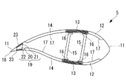
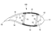
また、図10に示すように、近年では、軽量性と強度の両方の要求を満たすスパーキャップ構造を有する風車回転翼100が提案されている。風車回転翼100は、後述する外皮材11と、前縁サンドイッチ材12と、スパーキャップ材(主強度材)13と、後縁サンドイッチ材14と、シアウェブ15とを備えている。
前縁サンドイッチ材12と後縁サンドイッチ材14は、外皮材11と内皮材17をスキン材とし、PVC等の樹脂の発泡体や、バルサ等の木材をコア材とするサンドイッチ構造を有している。
なお、図10中の符号16は、スパーキャップ材13とシアウェブ15とを接続(連結)する接着剤である。
In addition, as shown in FIG. 10, in recent years, a wind
The leading
In addition, the code |
ところで、風車回転翼100を構成する各部材(より詳しくは、外皮材11、前縁サンドイッチ材12、スパーキャップ材13、後縁サンドイッチ材14、シアウェブ15)の材料強度(引っ張りおよび圧縮に対する強度)の安全率と、座屈強度の安全率とを同程度(例えば、2)に設定することができれば、風車回転翼の軽量化をさらに図ることができる。
By the way, the material strength (strength against tension and compression) of each member constituting the wind turbine rotor blade 100 (more specifically, the
しかしながら、図10に示す風車回転翼100では、材料強度を100%発揮させる前に、フラップ方向(背腹方向:図10において上下方向)の荷重に対してスパーキャップ材13で座屈が生じ、エッジ方向(前縁後縁方向:フラップ方向と直交する方向)の荷重に対して後縁サンドイッチ材14および/または後縁サンドイッチ材14の後縁端よりも後縁18側に位置する背側および/または腹側の外皮材11で座屈が生じるおそれがある。
However, in the wind
ここで、フラップ方向の荷重に対してスパーキャップ材13の座屈強度を上げるには、スパーキャップ材13の断面積を同等に維持しながら、スパーキャップ材13の幅(コード方向(図10において左右方向)の長さ)を狭くしつつスパーキャップ材13を厚くし、およびシアウェブ15の間隔(前縁側に位置するシアウェブ15と、後縁側に位置するシアウェブ15との間の距離)を狭くすればよい。
しかしその反面、後縁サンドイッチ材14の幅(コード方向(図10において左右方向)の長さ)が広くなり、エッジ方向の荷重に対する後縁サンドイッチ材14の座屈強度がますます低下してしまうといった問題点があった。
Here, in order to increase the buckling strength of the
However, on the other hand, the width of the trailing edge sandwich material 14 (length in the cord direction (left and right direction in FIG. 10)) is widened, and the buckling strength of the trailing
本発明は、上記の事情に鑑みてなされたもので、エッジ方向の荷重に対する座屈強度を向上させることができ、座屈強度の安全率を材料強度の安全率に近づけることができて、さらなる軽量化を図ることができる風車回転翼を提供することを目的とする。 The present invention has been made in view of the above circumstances, can improve the buckling strength against the load in the edge direction, can bring the safety factor of buckling strength closer to the safety factor of material strength, and further An object of the present invention is to provide a wind turbine rotor blade that can be reduced in weight.
本発明は、上記課題を解決するため、以下の手段を採用した。
本発明に係る風車回転翼は、繊維強化プラスチックで形成された外皮材と、シアウェブと、このシアウェブよりも後縁側に配置された後縁サンドイッチ材とを有する風車回転翼であって、前記後縁サンドイッチ材の後縁端よりも後縁側に位置する背側の外皮材または前記後縁サンドイッチ材の後縁端近傍と、前記後縁サンドイッチ材の後縁端よりも後縁側に位置する腹側の外皮材または前記後縁サンドイッチ材の後縁端近傍とが、補強材を介して連結されており、前記補強材が、軽量コア材と、この軽量コア材の背側に配置される背側スキン材と、前記軽量コア材の腹側に配置される腹側スキン材とを備え、前記軽量コア材、前記背側スキン材、および前記腹側スキン材が一体に形成されているとともに、前記背側スキン材および/または前記腹側スキン材は、翼長手方向に強化繊維が配向された繊維強化プラスチックで形成されており、前記軽量コア材、前記背側スキン材、および前記腹側スキン材の外側に配置された第2のスキン材を備え、前記軽量コア材、前記背側スキン材、前記腹側スキン材、および前記第2のスキン材が一体に形成されている。
The present invention employs the following means in order to solve the above problems.
A windmill rotor blade according to the present invention is a windmill rotor blade having an outer skin material formed of a fiber reinforced plastic, a shear web, and a trailing edge sandwich material arranged on the trailing edge side of the shear web. A dorsal skin material located on the rear edge side of the rear edge edge of the sandwich material or a vicinity of the rear edge edge of the rear edge sandwich material, and an abdominal side located on the rear edge side of the rear edge edge of the rear edge sandwich material. The outer skin material or the rear edge vicinity of the trailing edge sandwich material is connected via a reinforcing material, and the reinforcing material is disposed on the back side of the lightweight core material and the lightweight core material. And a ventral skin material disposed on the ventral side of the lightweight core material, wherein the lightweight core material, the dorsal skin material, and the ventral skin material are integrally formed, and the spine Side skin material and / or front The ventral skin material is formed of fiber reinforced plastic in which reinforcing fibers are oriented in the longitudinal direction of the wing, and is disposed outside the lightweight core material, the dorsal skin material, and the ventral skin material. The light-weight core material, the back skin material, the ventral skin material, and the second skin material are integrally formed .
本発明に係る風車回転翼によれば、後縁サンドイッチ材の後縁端よりも後縁側に位置する背側の外皮材または前記後縁サンドイッチ材の後縁端近傍と、後縁サンドイッチ材の後縁端よりも後縁側に位置する腹側の外皮材または前記後縁サンドイッチ材の後縁端近傍とが、補強材を介して連結されることとなるので、後縁部におけるエッジ方向の曲げ剛性を向上させることができ、後縁部におけるエッジ方向の荷重に対する座屈強度を向上させることができて、座屈強度の安全率を材料強度の安全率に近づけることができ、さらなる軽量化を図ることができる。 According to the wind turbine rotor blade of the present invention, the dorsal outer skin material or the vicinity of the trailing edge of the trailing edge sandwich material located on the trailing edge side with respect to the trailing edge of the trailing edge sandwich material, and the rear edge sandwich material Since the outer skin material located on the rear edge side of the edge edge or the vicinity of the rear edge edge of the rear edge sandwich material is connected via the reinforcing material, the bending rigidity in the edge direction at the rear edge portion The buckling strength against the load in the edge direction at the trailing edge can be improved, the safety factor of the buckling strength can be brought close to the safety factor of the material strength, and the weight can be further reduced. be able to.
また、本発明に係る風車回転翼によれば、背側スキン材および/または腹側スキン材を構成する強化繊維が、翼長手方向に沿って配向されているので、後縁部におけるエッジ方向の曲げ剛性をさらに向上させることができ、後縁部におけるエッジ方向の荷重に対する座屈強度をさらに向上させることができて、座屈強度の安全率を材料強度の安全率にさらに近づけることができ、さらなる軽量化を図ることができる。 Further , according to the wind turbine rotor blade according to the present invention, the reinforcing fibers constituting the back skin material and / or the ventral skin material are oriented along the blade longitudinal direction. The bending rigidity can be further improved, the buckling strength against the load in the edge direction at the trailing edge can be further improved, and the safety factor of buckling strength can be made closer to the safety factor of material strength, Further weight reduction can be achieved.
さらに、本発明に係る風車回転翼によれば、背側の外皮材と腹側の外皮材との翼長手方向の相対変位が抑制されることとなるので、背側の外皮材と腹側の外皮材との翼長手方向の相対変位による軽量コア材のせん断破壊を防止することができる。 Furthermore, according to the wind turbine rotor blade according to the present invention, since the relative displacement in the longitudinal direction of the back side skin material and the abdominal side skin material is suppressed, the back side skin material and the abdominal side skin material. It is possible to prevent the light core material from being sheared by the relative displacement in the blade longitudinal direction.
本発明に係る風力発電用風車は、後縁部におけるエッジ方向の曲げ剛性を向上させることができ、後縁部におけるエッジ方向の荷重に対する座屈強度を向上させることができて、座屈強度の安全率を材料強度の安全率に近づけることができ、さらなる軽量化を図ることができる風車回転翼を具備している。 The wind turbine for wind power generation according to the present invention can improve the bending rigidity in the edge direction at the trailing edge, can improve the buckling strength against the load in the edge direction at the trailing edge, and can improve the buckling strength. A wind turbine rotor blade that can bring the safety factor close to the safety factor of the material strength and can further reduce the weight is provided.
本発明に係る風力発電用風車によれば、ローターヘッドと風車回転翼の根元部とを連結する回転軸受けやローターヘッド内に設置されて風車翼に回転運動を与える連結軸の軽量化を図ることができ、これら風車回転翼およびローターヘッドを支持するタワーに加わる荷重を低減させることができる。 According to the wind turbine for wind power generation according to the present invention, it is possible to reduce the weight of a rotating shaft that connects the rotor head and the root portion of the wind turbine rotor blade, or a connecting shaft that is installed in the rotor head and that provides rotational motion to the wind turbine blade. The load applied to the tower that supports the wind turbine rotor blades and the rotor head can be reduced.
本発明によれば、エッジ方向の荷重に対する座屈強度を向上させることができ、座屈強度の安全率を材料強度の安全率に近づけることができて、さらなる軽量化を図ることができるという効果を奏する。 According to the present invention, the buckling strength against the load in the edge direction can be improved, the safety factor of buckling strength can be brought close to the safety factor of material strength, and further weight reduction can be achieved. Play.
以下、本発明に係る風車回転翼の第1参考実施形態について、図1から図3を参照しながら説明する。
図1は本実施形態に係る風車回転翼を具備した風力発電用風車を示す側面図、図2は本実施形態に係る風車回転翼の断面図、図3は図2の要部を拡大した断面図である。
Hereinafter, a first reference embodiment of a wind turbine rotor blade according to the present invention will be described with reference to FIGS. 1 to 3.
FIG. 1 is a side view showing a wind turbine for wind power generation provided with a wind turbine rotor blade according to the present embodiment, FIG. 2 is a cross-sectional view of the wind turbine rotor blade according to the present embodiment, and FIG. 3 is an enlarged cross-sectional view of the main part of FIG. FIG.
図1に示すように、風力発電用風車1は、基礎B上に立設される支柱(「タワー」ともいう。)2と、支柱2の上端に設置されるナセル3と、略水平な軸線周りに回転可能にしてナセル3に設けられるローターヘッド4とを有している。
ローターヘッド4には、その回転軸線周りに放射状にして複数枚(例えば、3枚)の風車回転翼5が取り付けられている。これにより、ローターヘッド4の回転軸線方向から風車回転翼5に当たった風の力が、ローターヘッド4を回転軸線周りに回転させる動力に変換されるようになっている。
As shown in FIG. 1, a
A plurality of (for example, three) wind
支柱2は、複数個(例えば、3個)のユニット(図示せず)を上下に連結した構成とされている。
また、ナセル3は、支柱2を構成するユニットのうち、最上部に設けられるユニット上に設置されており、支柱2の上端に取り付けられるナセル台板(図示せず)と、このナセル台板を上方から覆うカバー6とを有している。
The
The nacelle 3 is installed on a unit provided at the uppermost part of the units constituting the
図2に示すように、風車回転翼5は、軽量性と強度の両方の要求を満たすスパーキャップ構造とされており、外皮材11と、前縁サンドイッチ材12と、スパーキャップ材(主強度材)13と、後縁サンドイッチ材14と、シアウェブ(桁材)15とを備えている。
前縁サンドイッチ材12と後縁サンドイッチ材14は、外皮材11と内皮材17をスキン材とし、PVC等の樹脂の発泡体や、バルサ等の木材をコア材とするサンドイッチ構造を有している。
As shown in FIG. 2, the
The leading
外皮材11、スパーキャップ材13および内皮材17はそれぞれ、繊維強化プラスチック(FRP)で形成(構成)されている。スパーキャップ材13は、繊維強化プラスチックを多層に積層した部材であり、シアウェブ15の背側(図2において上側)の端面および腹側(図2において下側)の端面に接するようにして、風車回転翼5の背側および腹側に、それぞれ一つずつ設けられている。また、スパーキャップ材13とシアウェブ15とは、常温で硬化する接着剤16を介して接続(連結)されている。
The
このようなスパーキャップ構造では、主として、繊維強化プラスチックで形成されているスパーキャップ材13によって風車回転翼5のフラップ方向の曲げ強度が保たれ、前縁サンドイッチ材12および後縁サンドイッチ材14は、風車回転翼5の座屈強度を保つために補助的に使用されている。
In such a spar cap structure, the bending strength in the flap direction of the
さて、本実施形態に係る風車回転翼5では、後縁サンドイッチ材14の後縁端よりも後縁18側に位置する背側の外皮材11または前記後縁サンドイッチ材の後縁端近傍と、腹側の外皮材11または前記後縁サンドイッチ材の後縁端近傍との間に、補強材19が設けられている(配置されている)。
図2または図3に示すように、補強材19は、軽量コア材20と、軽量コア材20の背側に配置される(背側)スキン材21と、軽量コア材20の腹側に配置される(腹側)スキン材22とを備えている。
Now, in the
As shown in FIG. 2 or 3, the reinforcing
軽量コア材20は、PVC等の樹脂の発泡体や、バルサ等の木材で形成(構成)されており、スキン材21とスキン材22との間に挟み込まれている。
スキン材21,22はそれぞれ、軽量コア材20の対応(対向)する端面のコード方向(図2および図3において左右方向)の長さと同じ長さを有している。また、スキン材21,22はそれぞれ、風車回転翼5の翼長手方向(図2および図3において紙面に垂直な方向)に強化繊維(図示せず)が配向された繊維強化プラスチックで形成(構成)されている。
The
Each of the
スキン材21は、軽量コア材20の背側の端面に接し、スキン材22は、軽量コア材20の腹側の端面に接しており、軽量コア材20およびスキン材21,22は、一体に形成(構成)されている。また、外皮材11とスキン材21、外皮材11とスキン材22とはそれぞれ、常温で硬化する接着剤23を介して接続(連結)されている。
The
本実施形態に係る風車回転翼5によれば、後縁サンドイッチ材14の後縁端よりも後縁18側に位置する背側の外皮材11または前記後縁サンドイッチ材の後縁端近傍と、後縁サンドイッチ材14の後縁端よりも後縁18側に位置する腹側の外皮材11または前記後縁サンドイッチ材の後縁端近傍とが、補強材19を介して連結されることとなるので、後縁部におけるエッジ方向の曲げ剛性を向上させることができ、後縁部におけるエッジ方向の荷重に対する座屈強度を向上させることができて、座屈強度の安全率を材料強度の安全率に近づけることができ、さらなる軽量化を図ることができる。
そして、その結果、後縁サンドイッチ材14の幅(コード方向(図2において左右方向)の長さ)が広くなっても、エッジ方向の荷重に対する後縁サンドイッチ材14の座屈強度の低下を防げるので、シアウェブ15のコード方向の間隔、すなわち、前縁側に位置するシアウェブ15と、後縁側に位置するシアウェブ15との間の距離を狭くすることができ、スパーキャップ材13の幅を狭くする(このとき、スパーキャップ材13の断面積は同等に維持しながら、スパーキャップ材13を厚くする)ことができて、フラップ方向の荷重に対するスパーキャップ材13の座屈強度を向上させることができる。
According to the
As a result, even if the width of the trailing edge sandwich material 14 (length in the cord direction (left and right direction in FIG. 2)) is widened, it is possible to prevent the buckling strength of the trailing
また、本実施形態に係る風車回転翼5によれば、スキン材21,22を構成する強化繊維が、翼長手方向に沿って配向されているので、後縁部におけるエッジ方向の曲げ剛性をさらに向上させることができ、後縁部におけるエッジ方向の荷重に対する座屈強度をさらに向上させることができて、座屈強度の安全率を材料強度の安全率にさらに近づけることができ、さらなる軽量化を図ることができる。
Further, according to the
さらに、本実施形態に係る風車回転翼5を具備した風力発電用風車1によれば、ローターヘッド4と風車回転翼の根元部とを連結する回転軸受け(図示せず)やローターヘッド4内に設置されて風車翼に回転運動を与える連結軸(図示せず)の軽量化を図ることができ、これら風車回転翼5およびローターヘッド4を支持するタワー2に加わる荷重を低減させることができる。
Furthermore, according to the
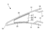
本発明に係る風車回転翼の第2参考実施形態について、図4を参照しながら説明する。
図4は本実施形態に係る風車回転翼の要部を拡大した断面図であって、図3と同様の図である。
A second reference embodiment of the wind turbine rotor blade according to the present invention will be described with reference to FIG.
FIG. 4 is an enlarged cross-sectional view of the main part of the wind turbine rotor blade according to the present embodiment, which is the same as FIG.
本実施形態に係る風車回転翼30は、補強材19の代わりに補強材31を備えているという点で上述した第1参考実施形態のものと異なる。その他の構成要素については上述した第1参考実施形態のものと同じであるので、ここではそれら構成要素についての説明は省略する。
なお、上述した実施形態と同一の部材には同一の符号を付している。
The
In addition, the same code | symbol is attached | subjected to the member same as embodiment mentioned above.
図4に示すように、本実施形態に係る補強材31は、後縁桁材32と、後縁桁材32の背側に配置される(背側)スキン材21と、後縁桁材32の腹側に配置される(腹側)スキン材22とを備えている。
As shown in FIG. 4, the reinforcing member 31 according to this embodiment includes a trailing edge beam member 32, a
後縁桁材32は、断面視I形状を呈する部材であり、繊維強化プラスチック(FRP)のみで形成される場合や、PVC等の樹脂の発泡体や、バルサ等の木材とともに形成(構成)される場合があり、スキン材21とスキン材22との間に挟み込まれている。
スキン材21,22はそれぞれ、後縁桁材32の対応(対向)する端面のコード方向(図4において左右方向)の長さ(断面視I形状のフランジ長さ)よりも長くなるように形成(構成)されている。
スキン材21は、後縁桁材32の背側の端面に接し、スキン材22は、後縁桁材32の腹側の端面に接しており、後縁桁材32およびスキン材21,22は、一体に形成(構成)されている。
The trailing edge girder 32 is a member having an I-shaped cross-sectional view, and is formed (configured) together with a fiber reinforced plastic (FRP) alone, a resin foam such as PVC, or wood such as balsa. And is sandwiched between the
Each of the
The
本実施形態に係る風車回転翼30の作用効果は、上述した第1参考実施形態と同じであるので、ここではその説明を省略する。
Since the effect of the wind
本発明に係る風車回転翼の第3参考実施形態について、図5を参照しながら説明する。
図5は本実施形態に係る風車回転翼の要部を拡大した断面図であって、図3と同様の図である。
A third reference embodiment of the wind turbine rotor blade according to the present invention will be described with reference to FIG.
FIG. 5 is an enlarged cross-sectional view of the main part of the wind turbine rotor blade according to the present embodiment, which is the same as FIG.
本実施形態に係る風車回転翼40は、補強材19の代わりに補強材41を備えているという点で上述した第1参考実施形態のものと異なる。その他の構成要素については上述した第1参考実施形態のものと同じであるので、ここではそれら構成要素についての説明は省略する。
なお、上述した実施形態と同一の部材には同一の符号を付している。
The wind
In addition, the same code | symbol is attached | subjected to the member same as embodiment mentioned above.
図5に示すように、本実施形態に係る補強材41は、コの字形状桁材42と、コの字形状桁材42の背側に配置される(背側)スキン材21と、コの字形状桁材42の腹側に配置される(腹側)スキン材22とを備えている。
As shown in FIG. 5, the reinforcing member 41 according to this embodiment includes a U-shaped girder 42, a
コの字形状桁材42は、繊維強化プラスチック(FRP)のみで形成される場合や、PVC等の樹脂の発泡体や、バルサ等の木材とともに形成(構成)される場合があり、断面視コの字形状を呈する部材であり、スキン材21とスキン材22との間に挟み込まれている。
スキン材21,22はそれぞれ、コの字形状桁材42の対応(対向)する端面のコード方向(図5において左右方向)の長さと同じ長さを有している。
スキン材21は、コの字形状桁材42の背側の端面に接し、スキン材22は、コの字形状桁材42の腹側の端面に接しており、コの字形状桁材42およびスキン材21,22は、一体に形成(構成)されている。
The U-shaped girder 42 may be formed (configured) only with a fiber reinforced plastic (FRP) or with a foamed resin such as PVC or wood such as balsa. This is a member exhibiting a letter shape, and is sandwiched between the
Each of the
The
本実施形態に係る風車回転翼40の作用効果は、上述した第1参考実施形態と同じであるので、ここではその説明を省略する。
Since the effect of the wind
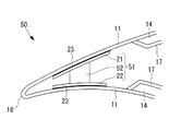
本発明に係る風車回転翼の第4参考実施形態について、図6を参照しながら説明する。
図6は本実施形態に係る風車回転翼の要部を拡大した断面図であって、図3と同様の図である。
A fourth reference embodiment of the wind turbine rotor blade according to the present invention will be described with reference to FIG.
FIG. 6 is an enlarged cross-sectional view of a main part of the wind turbine rotor blade according to the present embodiment, which is the same as FIG.
本実施形態に係る風車回転翼50は、補強材19の代わりに補強材51を備えているという点で上述した第1参考実施形態のものと異なる。その他の構成要素については上述した第1参考実施形態のものと同じであるので、ここではそれら構成要素についての説明は省略する。
なお、上述した実施形態と同一の部材には同一の符号を付している。
The wind
In addition, the same code | symbol is attached | subjected to the member same as embodiment mentioned above.
図6に示すように、本実施形態に係る補強材51は、台形形状桁材52と、台形形状桁材52の背側に配置される(背側)スキン材21と、台形形状桁材52の腹側に配置される(腹側)スキン材22とを備えている。
As shown in FIG. 6, the reinforcing
台形形状桁材52は、繊維強化プラスチック(FRP)のみで形成される場合や、PVC等の樹脂の発泡体や、バルサ等の木材とともに形成(構成)される場合があり、スキン材21とスキン材22との間に挟み込まれている。
スキン材21,22はそれぞれ、台形形状桁材52の対応(対向)する端面のコード方向(図6において左右方向)の長さよりも長くなるように形成(構成)されている。
スキン材21は、台形形状桁材52の背側の端面に接し、スキン材22は、台形形状桁材52の腹側の端面に接しており、台形形状桁材52およびスキン材21,22は、一体に形成(構成)されている。
The
Each of the
The
本実施形態に係る風車回転翼50の作用効果は、上述した第1参考実施形態と同じであるので、ここではその説明を省略する。
Since the effect of the
本発明に係る風車回転翼の第1実施形態について、図7を参照しながら説明する。
図7は本実施形態に係る風車回転翼の要部を拡大した断面図であって、図3と同様の図である。
A first embodiment of a wind turbine rotor blade according to the present invention will be described with reference to FIG.
FIG. 7 is an enlarged cross-sectional view of the main part of the wind turbine rotor blade according to the present embodiment, which is the same as FIG.
本実施形態に係る風車回転翼60は、補強材19の代わりに補強材61を備えているという点で上述した第1参考実施形態のものと異なる。その他の構成要素については上述した第1参考実施形態のものと同じであるので、ここではそれら構成要素についての説明は省略する。
なお、上述した実施形態と同一の部材には同一の符号を付している。
The wind
In addition, the same code | symbol is attached | subjected to the member same as embodiment mentioned above.
図7に示すように、本実施形態に係る補強材61は、第1参考実施形態のところで説明した補強材19の周囲(外側)を(第2の)スキン材62で覆うようにしたものである。すなわち、本実施形態に係る補強材61は、軽量コア材20と、軽量コア材20の背側に配置される(第1の)スキン材21と、軽量コア材20の腹側に配置される(第1の)スキン材22と、軽量コア材20およびスキン材21,22の外側を取り囲むように配置されたスキン材62とを備えている。
As shown in FIG. 7, the reinforcing
スキン材62は、例えば、強化繊維が、風車回転翼60の翼長手方向(図7において紙面に垂直な方向)に対して+45°傾斜して配向された+45°繊維強化樹脂層(図示せず)と、風車回転翼60の翼長手方向に対して−45°傾斜して配向された−45°繊維強化樹脂層(図示せず)とが順次積層されたダブルバイアスの繊維強化プラスチックである。
スキン材62は、スキン材21の背側の端面、スキン材22の腹側の端面、軽量コア材20の前縁側の端面、および軽量コア材20の後縁側の端面に接しており、軽量コア材20およびスキン材21,22,62は、一体に形成(構成)されている。また、外皮材11とスキン材62とは、常温で硬化する接着剤23を介して接続(連結)されている。
The
The
本実施形態に係る風車回転翼60によれば、背側の外皮材11と腹側の外皮材11との翼長手方向の相対変位が抑制されることとなるので、背側の外皮材11と腹側の外皮材11との翼長手方向の相対変位による軽量コア材20のせん断破壊を防止することができる。
その他の作用効果は、上述した第1参考実施形態のものと同じであるので、ここではその説明を省略する。
According to the wind
Other functions and effects are the same as those of the above-described first reference embodiment, and thus description thereof is omitted here.
本発明に係る風車回転翼の第2実施形態について、図8を参照しながら説明する。
図8は本実施形態に係る風車回転翼の要部を拡大した断面図であって、図6と同様の図である。
A second embodiment of the wind turbine rotor according to the present invention will be described with reference to FIG.
FIG. 8 is an enlarged cross-sectional view of a main part of the wind turbine rotor blade according to the present embodiment, which is the same as FIG.
本実施形態に係る風車回転翼70は、補強材51の代わりに補強材71を備えているという点で上述した第4参考実施形態のものと異なる。その他の構成要素については上述した第4参考実施形態のものと同じであるので、ここではそれら構成要素についての説明は省略する。
なお、上述した実施形態と同一の部材には同一の符号を付している。
The wind
In addition, the same code | symbol is attached | subjected to the member same as embodiment mentioned above.
図8に示すように、本実施形態に係る補強材71は、第4参考実施形態のところで説明した補強材51の周囲(外側)を(第2の)スキン材72で覆うようにしたものである。すなわち、本実施形態に係る補強材71は、台形形状桁材52と、台形形状桁材52の背側に配置される(第1の)スキン材21と、台形形状桁材52の腹側に配置される(第1の)スキン材22と、断面視台形形状を呈する台形形状桁材52およびスキン材21,22の外側を取り囲むように配置された、断面視(略)コ字形状を呈するスキン材72とを備えている。
As shown in FIG. 8, the reinforcing
スキン材72は、例えば、強化繊維が、風車回転翼70の翼長手方向(図8において紙面に垂直な方向)に対して+45°傾斜して配向された+45°繊維強化樹脂層(図示せず)と、風車回転翼70の翼長手方向に対して−45°傾斜して配向された−45°繊維強化樹脂層(図示せず)とが順次積層されたダブルバイアスの繊維強化プラスチックである。
スキン材72は、スキン材21の腹側の端面およびスキン材22の背側の端面とそれぞれ部分的に接合されているとともに、台形形状桁材52の前縁側の端面全体および台形形状桁材52の後縁側の端面全体とそれぞれ接合されており、台形形状桁材52およびスキン材21,22,72は、一体に形成(構成)されている。また、外皮材11とスキン材21、外皮材11とスキン材22とはそれぞれ、常温で硬化する接着剤23を介して接続(連結)されている。
The
The
本実施形態に係る風車回転翼70の作用効果は、上述した第1実施形態と同じであるので、ここではその説明を省略する。
Since the effect of the wind
なお、補強材19,31,41,51,61,および71はいずれも、図2や図10示す構造を有する風車回転翼のみに適用され得るものではなく、例えば、図9に示す構造を有する風車回転翼90、すなわち、ボックス構造のシアウェブ91を備えた風車回転翼90にも適用することができる。シアウェブ91の背側の端面と外皮材11の内面、シアウェブ91の腹側の端面と外皮材11の内面とはそれぞれ、常温で硬化する接着剤92を介して接続(連結)されている。
Note that all of the reinforcing
また、補強材19,31,41,51,61,および71はいずれも、図2や図10示す構造を有する風車回転翼のみに適用され得るものではなく、例えば、図11に示す構造を有する風車回転翼110、すなわち、背側に配置された後縁サンドイッチ材14の後縁端が、腹側に配置された後縁サンドイッチ材14の後縁端よりも後縁側に、あるいは後縁18近傍まで延びている風車回転翼110にも適用することができる。この場合、補強材19,31,41,51,61,71は、背側の後縁サンドイッチ材14の後縁部に位置する内皮材17と、腹側の外皮材11または後縁サンドイッチ材14の後縁端近傍との間に設けられることになる。
Further, any of the reinforcing
さらに、補強材19,31,41,51,61,および71はいずれも、図2や図10示す構造を有する風車回転翼のみに適用され得るものではなく、例えば、図12に示す構造を有する風車回転翼120、すなわち、腹側に配置された後縁サンドイッチ材14の後縁端が、背側に配置された後縁サンドイッチ材14の後縁端よりも後縁側に、あるいは後縁18近傍まで延びている風車回転翼120にも適用することができる。この場合、補強材19,31,41,51,61,71は、腹側の後縁サンドイッチ材14の後縁部に位置する内皮材17と、背側の外皮材11または後縁サンドイッチ材14の後縁端近傍との間に設けられることになる。
Furthermore, none of the reinforcing
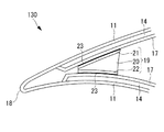
さらにまた、補強材19,31,41,51,61,および71はいずれも、図2や図10示す構造を有する風車回転翼のみに適用され得るものではなく、例えば、図13に示す構造を有する風車回転翼130、すなわち、背側および腹側に配置された後縁サンドイッチ材14の後縁端が、上述した第1参考実施形態から第2実施形態のところで説明した後縁サンドイッチ材14の後縁端よりも後縁側に、あるいは後縁18近傍まで延びている風車回転翼130にも適用することができる。この場合、補強材19,31,41,51,61,71は、背側の後縁サンドイッチ材14の後縁部に位置する内皮材17と、腹側の後縁サンドイッチ材14の後縁部に位置する内皮材17との間に設けられることになる。
なお、図9、図11、図12、図13には、補強材の一具体例として第1参考実施形態のところで説明した補強材19を示しているが、これはその他の補強材31,41,51,61,71を排除するものではない。
Furthermore, none of the reinforcing
9, FIG. 11, FIG. 12, and FIG. 13 show the reinforcing
1 風力発電用風車
2 支柱(タワー)
3 ナセル
4 ローターヘッド
5 風車回転翼
6 ナセルカバー
11 外皮材
12 前縁サンドイッチ材
13 スパーキャップ材(主強度材)
14 後縁サンドイッチ材
15 シアウェブ
16 接着剤
17 内皮材
18 後縁
19 補強材
20 軽量コア材
21 スキン材(背側スキン材)
22 スキン材(腹側スキン材)
23 接着剤
30 風車回転翼
31 補強材
32 後縁桁材
40 風車回転翼
41 補強材
42 コの字形状桁材
50 風車回転翼
51 補強材
52 台形形状桁材
60 風車回転翼
61 補強材
62 (第2の)スキン材
70 風車回転翼
71 補強材
72 (第2の)スキン材
90 風車回転翼
91 シアウェブ(桁材)
92 接着剤
B 基礎
1 Windmill for
3 Nacelle 4
14 Rear
22 Skin material (ventral skin material)
23 Adhesive 30 Windmill rotor blade 31 Reinforcement material 32 Trailing
92 Adhesive B Basic
Claims (2)
前記後縁サンドイッチ材の後縁端よりも後縁側に位置する背側の外皮材または前記後縁サンドイッチ材の後縁端近傍と、前記後縁サンドイッチ材の後縁端よりも後縁側に位置する腹側の外皮材または前記後縁サンドイッチ材の後縁端近傍とが、補強材を介して連結されており、
前記補強材が、軽量コア材と、この軽量コア材の背側に配置される背側スキン材と、前記軽量コア材の腹側に配置される腹側スキン材とを備え、
前記軽量コア材、前記背側スキン材、および前記腹側スキン材が一体に形成されているとともに、
前記背側スキン材および/または前記腹側スキン材は、翼長手方向に強化繊維が配向された繊維強化プラスチックで形成されており、
前記軽量コア材、前記背側スキン材、および前記腹側スキン材の外側に配置された第2のスキン材を備え、
前記軽量コア材、前記背側スキン材、前記腹側スキン材、および前記第2のスキン材が一体に形成されていることを特徴とする風車回転翼。 A windmill rotor blade having a skin material formed of fiber-reinforced plastic, a shear web, and a trailing edge sandwich material disposed on the trailing edge side of the shear web,
It is located on the back side of the rear edge of the trailing edge sandwich material or in the vicinity of the trailing edge of the trailing edge sandwich material, or on the rear edge side of the trailing edge sandwich material. The ventral skin material or the vicinity of the trailing edge of the trailing edge sandwich material is connected via a reinforcing material ,
The reinforcing material comprises a lightweight core material, a back skin material disposed on the back side of the lightweight core material, and a ventral skin material disposed on the ventral side of the lightweight core material,
The lightweight core material, the back skin material, and the ventral skin material are integrally formed,
The dorsal skin material and / or the ventral skin material is formed of a fiber reinforced plastic in which reinforcing fibers are oriented in the longitudinal direction of the wing,
A second skin material disposed outside the lightweight core material, the back skin material, and the ventral skin material;
The windmill rotor blade according to claim 1, wherein the lightweight core material, the back skin material, the ventral skin material, and the second skin material are integrally formed .
Applications Claiming Priority (1)
| Application Number | Priority Date | Filing Date | Title |
|---|---|---|---|
| PCT/JP2009/071574 WO2011077545A1 (en) | 2009-12-25 | 2009-12-25 | Windmill rotary vane |
Publications (2)
| Publication Number | Publication Date |
|---|---|
| JPWO2011077545A1 JPWO2011077545A1 (en) | 2013-05-02 |
| JP5536103B2 true JP5536103B2 (en) | 2014-07-02 |
Family
ID=44195107
Family Applications (1)
| Application Number | Title | Priority Date | Filing Date |
|---|---|---|---|
| JP2011547158A Active JP5536103B2 (en) | 2009-12-25 | 2009-12-25 | Wind turbine rotor |
Country Status (8)
| Country | Link |
|---|---|
| US (1) | US8556590B2 (en) |
| EP (1) | EP2518311A4 (en) |
| JP (1) | JP5536103B2 (en) |
| CN (1) | CN102575649A (en) |
| AU (1) | AU2009357031A1 (en) |
| IN (1) | IN2012DN01230A (en) |
| MX (1) | MX2012001612A (en) |
| WO (1) | WO2011077545A1 (en) |
Families Citing this family (23)
| Publication number | Priority date | Publication date | Assignee | Title |
|---|---|---|---|---|
| DE102009033164A1 (en) * | 2009-07-13 | 2011-01-27 | Repower Systems Ag | Rotor blade of a wind energy plant and method for manufacturing a rotor blade of a wind turbine |
| US8556590B2 (en) * | 2009-12-25 | 2013-10-15 | Mitsubishi Heavy Industries, Ltd. | Wind-turbine rotor blade |
| JP5427597B2 (en) * | 2009-12-25 | 2014-02-26 | 三菱重工業株式会社 | Wind turbine rotor |
| GB201109412D0 (en) * | 2011-06-03 | 2011-07-20 | Blade Dynamics Ltd | A wind turbine rotor |
| US9458823B2 (en) * | 2011-12-12 | 2016-10-04 | General Electric Company | Wind turbine blade shear web connection assembly |
| CN103174600A (en) * | 2011-12-22 | 2013-06-26 | 华锐风电科技(集团)股份有限公司 | Fan blade |
| GB201217212D0 (en) | 2012-09-26 | 2012-11-07 | Blade Dynamics Ltd | Windturbine blade |
| DE102012217904A1 (en) * | 2012-10-01 | 2014-04-03 | Repower Systems Se | Fiber composite component and rotor blade |
| CN102927051A (en) * | 2012-11-15 | 2013-02-13 | 江苏中联风能机械有限公司 | Improved blade of large-sized air cooling axial flow fan |
| US9739260B2 (en) * | 2013-07-30 | 2017-08-22 | Lm Windpower A/S | Wind turbine blade having a bond line adjacent a sandwich panel of the blade |
| EP2927481B1 (en) * | 2014-03-31 | 2021-09-22 | Siemens Gamesa Renewable Energy A/S | Rotor blade for a wind turbine |
| US10066600B2 (en) | 2014-05-01 | 2018-09-04 | Tpi Composites, Inc. | Wind turbine rotor blade and method of construction |
| KR101678015B1 (en) * | 2014-12-30 | 2016-11-21 | 한국에너지기술연구원 | Composite blade having Local reinforcement structure |
| WO2017037930A1 (en) * | 2015-09-03 | 2017-03-09 | 積水化成品工業株式会社 | Windmill blade |
| CN105402084B (en) * | 2015-12-29 | 2017-11-10 | 南京高传机电自动控制设备有限公司 | A kind of novel wind motor combined blade |
| DE102016007675A1 (en) * | 2016-06-24 | 2017-12-28 | Senvion Gmbh | Trailing edge belt with rectangular cross section |
| FR3063774B1 (en) * | 2017-03-13 | 2021-06-11 | Arkema France | THERMOPLASTIC POLYMER COMPOSITE WIND TURBINE BLADE, PART OF THE BLADE AND MANUFACTURING METHOD |
| CN109895411B (en) * | 2017-12-08 | 2021-09-07 | 苏州天顺复合材料科技有限公司 | Web integral type bonding frock |
| US11131290B2 (en) * | 2019-06-25 | 2021-09-28 | General Electric Company | Scarf connection for a wind turbine rotor blade |
| CN110905719A (en) * | 2019-12-02 | 2020-03-24 | 三一重能有限公司 | Wind power blade and wind power generation equipment |
| CN112065658B (en) * | 2020-08-24 | 2022-07-08 | 河南恒聚新能源设备有限公司 | Moving blade and vertical axis turbine wind power generation device |
| CN112065656A (en) * | 2020-08-24 | 2020-12-11 | 河南恒聚新能源设备有限公司 | Guide vane and vertical axis turbine wind power generation device |
| CN113757036B (en) * | 2021-08-31 | 2023-02-28 | 株洲时代新材料科技股份有限公司 | Wind power blade with improved trailing edge structure and manufacturing method thereof |
Citations (3)
| Publication number | Priority date | Publication date | Assignee | Title |
|---|---|---|---|---|
| JPS57210171A (en) * | 1981-04-01 | 1982-12-23 | Messerschmitt Boelkow Blohm | Aerodynamical large-sized blade, particularly, rotor blade for large-sized air force device |
| US4976587A (en) * | 1988-07-20 | 1990-12-11 | Dwr Wind Technologies Inc. | Composite wind turbine rotor blade and method for making same |
| JP2002137307A (en) * | 2000-11-02 | 2002-05-14 | Toray Ind Inc | Blade structure of windmill made of fiber-reinforced resin |
Family Cites Families (17)
| Publication number | Priority date | Publication date | Assignee | Title |
|---|---|---|---|---|
| US5375324A (en) * | 1993-07-12 | 1994-12-27 | Flowind Corporation | Vertical axis wind turbine with pultruded blades |
| JP3825346B2 (en) | 2001-03-27 | 2006-09-27 | 三菱重工業株式会社 | Composite blade for wind turbine generator |
| US7802968B2 (en) * | 2005-07-29 | 2010-09-28 | General Electric Company | Methods and apparatus for reducing load in a rotor blade |
| US7438533B2 (en) * | 2005-12-15 | 2008-10-21 | General Electric Company | Wind turbine rotor blade |
| JP4699255B2 (en) * | 2006-03-24 | 2011-06-08 | 三菱重工業株式会社 | Windmill wing |
| WO2008086805A2 (en) | 2007-01-16 | 2008-07-24 | Danmarks Tekniske Universitet | Reinforced blade for wind turbine |
| US20090140527A1 (en) * | 2007-11-30 | 2009-06-04 | General Electric Company | Wind turbine blade stiffeners |
| US8622709B2 (en) * | 2008-06-05 | 2014-01-07 | Mitsubishi Heavy Industries, Ltd. | Wind turbine blade and wind power generator using the same |
| WO2009155920A1 (en) * | 2008-06-24 | 2009-12-30 | Danmarks Tekniske Universitet | A reinforced wind turbine blade |
| US8043065B2 (en) * | 2009-05-01 | 2011-10-25 | General Electric Company | Wind turbine blade with prefabricated leading edge segments |
| JP2011032988A (en) * | 2009-08-05 | 2011-02-17 | Nitto Denko Corp | Foam filler for wind turbine generator blade, foam filling part for wind turbine generator blade, wind turbine generator blade, wind turbine generator, and method of manufacturing wind turbine generator blade |
| JP2011032987A (en) * | 2009-08-05 | 2011-02-17 | Nitto Denko Corp | Reinforcing sheet for wind turbine generator blade, reinforcing structure of wind turbine generator blade, wind turbine generator, and method of reinforcing wind turbine generator blade |
| US8702397B2 (en) * | 2009-12-01 | 2014-04-22 | General Electric Company | Systems and methods of assembling a rotor blade for use in a wind turbine |
| JP5308323B2 (en) * | 2009-12-22 | 2013-10-09 | 三菱重工業株式会社 | Wind turbine blade and wind power generator using the same |
| JP5484892B2 (en) * | 2009-12-25 | 2014-05-07 | 三菱重工業株式会社 | Wind turbine rotor |
| JP5427597B2 (en) * | 2009-12-25 | 2014-02-26 | 三菱重工業株式会社 | Wind turbine rotor |
| US8556590B2 (en) * | 2009-12-25 | 2013-10-15 | Mitsubishi Heavy Industries, Ltd. | Wind-turbine rotor blade |
-
2009
- 2009-12-25 US US13/389,534 patent/US8556590B2/en active Active
- 2009-12-25 AU AU2009357031A patent/AU2009357031A1/en not_active Abandoned
- 2009-12-25 EP EP09852562.9A patent/EP2518311A4/en not_active Withdrawn
- 2009-12-25 CN CN200980161076XA patent/CN102575649A/en active Pending
- 2009-12-25 JP JP2011547158A patent/JP5536103B2/en active Active
- 2009-12-25 WO PCT/JP2009/071574 patent/WO2011077545A1/en active Application Filing
- 2009-12-25 IN IN1230DEN2012 patent/IN2012DN01230A/en unknown
- 2009-12-25 MX MX2012001612A patent/MX2012001612A/en not_active Application Discontinuation
Patent Citations (3)
| Publication number | Priority date | Publication date | Assignee | Title |
|---|---|---|---|---|
| JPS57210171A (en) * | 1981-04-01 | 1982-12-23 | Messerschmitt Boelkow Blohm | Aerodynamical large-sized blade, particularly, rotor blade for large-sized air force device |
| US4976587A (en) * | 1988-07-20 | 1990-12-11 | Dwr Wind Technologies Inc. | Composite wind turbine rotor blade and method for making same |
| JP2002137307A (en) * | 2000-11-02 | 2002-05-14 | Toray Ind Inc | Blade structure of windmill made of fiber-reinforced resin |
Also Published As
| Publication number | Publication date |
|---|---|
| MX2012001612A (en) | 2012-06-01 |
| CN102575649A (en) | 2012-07-11 |
| JPWO2011077545A1 (en) | 2013-05-02 |
| US20120141282A1 (en) | 2012-06-07 |
| IN2012DN01230A (en) | 2015-04-10 |
| EP2518311A4 (en) | 2014-03-05 |
| US8556590B2 (en) | 2013-10-15 |
| EP2518311A1 (en) | 2012-10-31 |
| WO2011077545A1 (en) | 2011-06-30 |
| AU2009357031A1 (en) | 2012-03-01 |
Similar Documents
| Publication | Publication Date | Title |
|---|---|---|
| JP5536103B2 (en) | Wind turbine rotor | |
| JP5427597B2 (en) | Wind turbine rotor | |
| JP5484892B2 (en) | Wind turbine rotor | |
| US8186964B2 (en) | Spar assembly for a wind turbine rotor blade | |
| WO2011078327A1 (en) | Rotary blade of windmill and method of manufacturing rotary blade of windmill | |
| US8632312B2 (en) | Reinforced blade for wind turbine | |
| US8485786B2 (en) | Reinforced blade for wind turbine | |
| US8075278B2 (en) | Shell structure of wind turbine blade having regions of low shear modulus | |
| JP2011137388A5 (en) | ||
| JP2011137386A5 (en) | ||
| KR20110100192A (en) | Wind turbine blade and wind turbine generator using the same | |
| EP2159414B1 (en) | Wind turbine blades with cross webs | |
| US20160290314A1 (en) | Wind turbine blade with wave shaped trailing edge | |
| BR112020003184B1 (en) | ROTOR BLADE ASSEMBLY AND CONNECTION STRUCTURE | |
| CN205977533U (en) | Blade subassembly and rotor and wind power installation and power generating equipment of variable propeller pitch angle | |
| CN114630959A (en) | Wind turbine blade | |
| JP6475767B2 (en) | Wind turbine blade and method for reinforcing wind turbine blade | |
| JP2020084812A (en) | Windmill blade and wind power generation device | |
| JP2005147080A (en) | Blade of horizontal axis wind mill |
Legal Events
| Date | Code | Title | Description |
|---|---|---|---|
| A131 | Notification of reasons for refusal |
Free format text: JAPANESE INTERMEDIATE CODE: A131 Effective date: 20130723 |
|
| A521 | Written amendment |
Free format text: JAPANESE INTERMEDIATE CODE: A523 Effective date: 20130924 |
|
| TRDD | Decision of grant or rejection written | ||
| A01 | Written decision to grant a patent or to grant a registration (utility model) |
Free format text: JAPANESE INTERMEDIATE CODE: A01 Effective date: 20140325 |
|
| A61 | First payment of annual fees (during grant procedure) |
Free format text: JAPANESE INTERMEDIATE CODE: A61 Effective date: 20140423 |
|
| R151 | Written notification of patent or utility model registration |
Ref document number: 5536103 Country of ref document: JP Free format text: JAPANESE INTERMEDIATE CODE: R151 |
|
| R250 | Receipt of annual fees |
Free format text: JAPANESE INTERMEDIATE CODE: R250 |