JP5535659B2 - Fluorescent material and method for producing fluorescent material - Google Patents
Fluorescent material and method for producing fluorescent material Download PDFInfo
- Publication number
- JP5535659B2 JP5535659B2 JP2010002027A JP2010002027A JP5535659B2 JP 5535659 B2 JP5535659 B2 JP 5535659B2 JP 2010002027 A JP2010002027 A JP 2010002027A JP 2010002027 A JP2010002027 A JP 2010002027A JP 5535659 B2 JP5535659 B2 JP 5535659B2
- Authority
- JP
- Japan
- Prior art keywords
- glass
- fluorescent material
- alkali
- rare earth
- liquid crystal
- Prior art date
- Legal status (The legal status is an assumption and is not a legal conclusion. Google has not performed a legal analysis and makes no representation as to the accuracy of the status listed.)
- Expired - Fee Related
Links
Images


Classifications
-
- C—CHEMISTRY; METALLURGY
- C03—GLASS; MINERAL OR SLAG WOOL
- C03C—CHEMICAL COMPOSITION OF GLASSES, GLAZES OR VITREOUS ENAMELS; SURFACE TREATMENT OF GLASS; SURFACE TREATMENT OF FIBRES OR FILAMENTS MADE FROM GLASS, MINERALS OR SLAGS; JOINING GLASS TO GLASS OR OTHER MATERIALS
- C03C3/00—Glass compositions
- C03C3/04—Glass compositions containing silica
- C03C3/076—Glass compositions containing silica with 40% to 90% silica, by weight
- C03C3/095—Glass compositions containing silica with 40% to 90% silica, by weight containing rare earths
-
- C—CHEMISTRY; METALLURGY
- C03—GLASS; MINERAL OR SLAG WOOL
- C03C—CHEMICAL COMPOSITION OF GLASSES, GLAZES OR VITREOUS ENAMELS; SURFACE TREATMENT OF GLASS; SURFACE TREATMENT OF FIBRES OR FILAMENTS MADE FROM GLASS, MINERALS OR SLAGS; JOINING GLASS TO GLASS OR OTHER MATERIALS
- C03C4/00—Compositions for glass with special properties
- C03C4/12—Compositions for glass with special properties for luminescent glass; for fluorescent glass
-
- C—CHEMISTRY; METALLURGY
- C09—DYES; PAINTS; POLISHES; NATURAL RESINS; ADHESIVES; COMPOSITIONS NOT OTHERWISE PROVIDED FOR; APPLICATIONS OF MATERIALS NOT OTHERWISE PROVIDED FOR
- C09K—MATERIALS FOR MISCELLANEOUS APPLICATIONS, NOT PROVIDED FOR ELSEWHERE
- C09K11/00—Luminescent, e.g. electroluminescent, chemiluminescent materials
- C09K11/08—Luminescent, e.g. electroluminescent, chemiluminescent materials containing inorganic luminescent materials
- C09K11/77—Luminescent, e.g. electroluminescent, chemiluminescent materials containing inorganic luminescent materials containing rare earth metals
- C09K11/7715—Luminescent, e.g. electroluminescent, chemiluminescent materials containing inorganic luminescent materials containing rare earth metals containing cerium
- C09K11/77214—Aluminosilicates
-
- H—ELECTRICITY
- H05—ELECTRIC TECHNIQUES NOT OTHERWISE PROVIDED FOR
- H05B—ELECTRIC HEATING; ELECTRIC LIGHT SOURCES NOT OTHERWISE PROVIDED FOR; CIRCUIT ARRANGEMENTS FOR ELECTRIC LIGHT SOURCES, IN GENERAL
- H05B33/00—Electroluminescent light sources
- H05B33/12—Light sources with substantially two-dimensional radiating surfaces
- H05B33/14—Light sources with substantially two-dimensional radiating surfaces characterised by the chemical or physical composition or the arrangement of the electroluminescent material, or by the simultaneous addition of the electroluminescent material in or onto the light source
Description
本発明は、一般的には、蛍光材料に関し、より特定的には、無アルカリガラスを原料とした蛍光材料に関する。また、本発明は上記蛍光材料を製造する方法に関する。 The present invention generally relates to a fluorescent material, and more particularly to a fluorescent material using alkali-free glass as a raw material. The present invention also relates to a method for producing the fluorescent material.
近年、液晶パネルを用いた液晶テレビなどの家電製品、パソコン、携帯端末などの製品が急速に普及している。ここで、上述した「液晶パネル」とは、貼り合せた2枚のガラス基板の内側に液晶材料を注入、封入し、各ガラス基板の外側に偏光板(樹脂)を貼り付けたものを指す。液晶パネルを用いた製品の普及に伴い、液晶パネルの廃棄物(廃液晶パネル)の数量も急激に増加しているが、環境との共存が期待される循環型社会の形成の中、廃液晶パネルについてもリサイクルし資源を有効に利用することが要望されている。 In recent years, home appliances such as a liquid crystal television using a liquid crystal panel, personal computers, portable terminals, and other products are rapidly spreading. Here, the above-mentioned “liquid crystal panel” refers to one in which a liquid crystal material is injected and sealed inside two bonded glass substrates, and a polarizing plate (resin) is bonded to the outside of each glass substrate. With the spread of products that use liquid crystal panels, the number of liquid crystal panel waste (waste liquid crystal panels) has also increased rapidly, but in the formation of a recycling society where coexistence with the environment is expected, waste liquid crystals Panels are also required to be recycled and effectively use resources.
現在、家電製品や情報機器などの廃棄物に含まれる液晶表示装置や液晶パネルは、廃棄物の量としては少ないこともあって、廃棄物の処理施設にて製品ごとに破砕された後、プラスチックを多量に含むシュレッダーダストと共に、埋め立て処理あるいは焼却処理されている。 Currently, liquid crystal display devices and liquid crystal panels contained in waste such as home appliances and information equipment are small in amount of waste, and after being crushed for each product in a waste treatment facility, plastic Along with shredder dust containing a large amount of waste, it is landfilled or incinerated.
液晶パネルの製造工場から排出される不良の廃液晶パネル、ならびに、家電製品、情報機器などの廃棄物に含まれる液晶表示装置、液晶パネルの処理方法として、特開2000−84531号公報(特許文献1)には、液晶パネルの製造工場や廃棄物の処理施設にて製品ごと破砕後、非鉄精錬炉に投入し珪石の代替材料として処理する方法が開示されており、一部で実施されている。この方法では、液晶パネル中のガラス成分は、スラグ中へ入り込む。 Japanese Patent Application Laid-Open No. 2000-84531 (Patent Document) discloses a waste liquid crystal panel discharged from a liquid crystal panel manufacturing factory, a liquid crystal display device included in wastes such as home appliances and information equipment, and a method for treating the liquid crystal panel. 1) discloses a method in which products are crushed at a liquid crystal panel manufacturing plant or waste disposal facility, and then put into a non-ferrous smelting furnace and treated as an alternative material for silica. . In this method, the glass component in the liquid crystal panel enters the slag.
また、特開2004−224686号公報(特許文献2)には、廃ガラスから高温溶融および高温の酸処理を経て作製した多孔質ガラスに希土類原子を吸着させた後、大気中または還元雰囲気中で焼成し、発光ガラスを作製する方法が開示されている。 Japanese Patent Application Laid-Open No. 2004-224686 (Patent Document 2) discloses a method in which rare earth atoms are adsorbed on porous glass produced from waste glass through high-temperature melting and high-temperature acid treatment, and then in the atmosphere or in a reducing atmosphere. A method for firing and producing a luminescent glass is disclosed.
液晶パネルは、省電力・省資源に貢献できる表示装置であるので、今後、高度情報化社会の進展に伴って、急激に生産量が増大するとともに、その表示面積も大型化することが予測され、これに伴って、今後、廃液晶パネルも、数・量ともに急激に増大すると予想される。したがって、液晶パネルの重量の大半を占めるガラス(液晶パネルガラス)についても、廃棄物の低減と資源を大切にする観点から、再生利用することが好ましい。しかしながら特許文献1に開示された方法では、セメント材料として再利用することを意図しているため、液晶パネルガラスはスラグとなり、ガラス自体として再生利用することはできない。 Since the LCD panel is a display device that can contribute to power and resource savings, it is predicted that the production volume will increase rapidly and the display area will increase with the progress of the advanced information society. Along with this, the number and amount of waste liquid crystal panels are expected to increase rapidly in the future. Therefore, glass (liquid crystal panel glass) occupying most of the weight of the liquid crystal panel is preferably recycled from the viewpoint of reducing waste and valuing resources. However, since the method disclosed in Patent Document 1 is intended to be reused as a cement material, the liquid crystal panel glass becomes slag and cannot be recycled as the glass itself.
資源有効利用の観点からは、回収された液晶パネルガラスを液晶パネルガラス自体として再びマテリアルリサイクルすることが望ましい。しかしながら、液晶パネルガラス表面に付着している不純物、ガラス組成の異なる数多くの品種が存在することなどの理由で、光学的特性、熱特性の厳しい仕様が求められる液晶パネルガラスにリサイクルすることは、技術的に確立されていない。そのため、回収した液晶パネルガラスの、液晶パネルガラス以外の高付加価値製品としての用途開発が課題となっている。 From the viewpoint of effective use of resources, it is desirable to recycle the recovered liquid crystal panel glass as the liquid crystal panel glass itself. However, recycling to liquid crystal panel glass that requires strict specifications for optical and thermal characteristics due to the presence of impurities on the surface of the liquid crystal panel glass and the presence of many varieties with different glass compositions. Not technically established. Therefore, application development of the collected liquid crystal panel glass as a high value-added product other than the liquid crystal panel glass has been an issue.
なお、液晶パネルガラスには無アルカリガラスと呼ばれるガラスが通常用いられている。無アルカリガラスは、液晶パネルの製造工程に適合するようにつくられた特殊なガラスであり、その歪点は650℃以上である。これに対し、びんガラス、建築用窓ガラス、ガラス繊維、食器ガラスなど幅広くガラス製品に用いられているソーダライムガラスの歪点は、550℃以下である。このように、100℃以上歪点が異なるため、一般的にガラス製品に使用されるソーダライムガラスの溶融加工設備で、再生利用のための無アルカリガラスの溶融加工を行うことは、加熱設備の性能、設備全般の耐熱性などの点で非常に困難である。また溶融温度の高い無アルカリガラスを、通常はソーダライムガラスを原料として使用する建築用窓ガラス、ガラス繊維、食器ガラスなどの汎用的な製品へ使用することは、エネルギー消費の観点からも不利となる。このように、通常のソーダライムガラス製品の原料としての用途に用いる方法は技術的に確立されていないのが現状である。このため、不要となった液晶パネルガラスの用途として、現状の製造工程の温度と比較し加工温度が上昇しない用途に用いる再資源化方法が望まれている。 Note that glass called non-alkali glass is usually used for the liquid crystal panel glass. The alkali-free glass is a special glass made so as to be compatible with the manufacturing process of the liquid crystal panel, and has a strain point of 650 ° C. or higher. On the other hand, the strain point of soda lime glass widely used for glass products such as bottle glass, architectural window glass, glass fiber, and tableware glass is 550 ° C. or lower. As described above, since the strain points are different by 100 ° C. or more, it is possible to perform melting processing of alkali-free glass for recycling in a soda lime glass melting processing facility generally used for glass products. It is very difficult in terms of performance and heat resistance of the entire equipment. In addition, it is disadvantageous from the viewpoint of energy consumption to use alkali-free glass with a high melting temperature for general-purpose products such as architectural window glass, glass fiber, and tableware glass that usually uses soda-lime glass as a raw material. Become. Thus, the present condition is that the method used for the use as a raw material of a normal soda-lime glass product is not technically established. For this reason, as a use of liquid crystal panel glass that has become unnecessary, there is a demand for a recycling method that is used for applications in which the processing temperature does not increase compared to the temperature of the current manufacturing process.
上述した特許文献2に記載された方法は、ガラス廃棄物に所定の割合の化合物を添加し高温溶融した後、高温の酸で処理を行うことにより、多孔質ガラスを作製する。さらに、作製した多孔質ガラスに希土類原子を吸着させ、大気中または還元雰囲気中で焼成することにより発光ガラスを得る方法である。この方法は、高温溶融の工程を経るため、加工温度の高い無アルカリガラスの再資源化方法としては、溶融温度が高く、多大なエネルギーを消費するといった課題がある。また、高温での酸処理、焼成工程を経るため処理が多段となり、複雑である。そのため、エネルギーコストおよび設備コストが高くなり、得られた発光ガラスは高価となる。また、この方法で作製した多孔質ガラスは、成分としてシリカのみを含むため、希土類イオンの溶解濃度に限度があるため、限られた発光強度しか得られない。 In the method described in Patent Document 2 described above, a porous glass is produced by adding a predetermined proportion of a compound to glass waste, melting it at a high temperature, and then treating it with a high-temperature acid. Furthermore, it is a method for obtaining a luminescent glass by adsorbing rare earth atoms to the produced porous glass and firing it in the air or in a reducing atmosphere. Since this method goes through a high-temperature melting step, there is a problem that a high melting temperature and a large amount of energy are consumed as a method for recycling alkali-free glass having a high processing temperature. In addition, since the acid treatment at a high temperature and the firing step are performed, the treatment is multistage and complicated. Therefore, energy cost and equipment cost become high, and the obtained luminescent glass becomes expensive. Moreover, since the porous glass produced by this method contains only silica as a component, there is a limit to the dissolution concentration of rare earth ions, so that only limited emission intensity can be obtained.
本発明は、上記課題を解決するためになされたものであって、その目的とするところは不要となり回収された無アルカリガラスを資源として有効利用可能な用途を提供し、さらに、強い発光強度を示す蛍光材料を提供することにある。 The present invention has been made in order to solve the above-mentioned problems. The purpose of the present invention is unnecessary, and it provides an application in which the recovered alkali-free glass can be effectively used as a resource. It is to provide the fluorescent material shown.
また、本発明の別の課題は、不要となり回収された無アルカリガラスを原料として用い、強い発光強度を有する蛍光材料の製造方法を提供することである。 Another object of the present invention is to provide a method for producing a fluorescent material having strong light emission intensity, using unnecessary alkali-free glass recovered as a raw material.
本発明の蛍光材料は、無アルカリガラスと、希土類原子とからなることを特徴とする。
本発明の蛍光材料は、無アルカリガラス95〜99.99重量%と、希土類原子0.01〜5重量%とからなることが、好ましい。
The fluorescent material of the present invention is characterized by comprising alkali-free glass and rare earth atoms.
The fluorescent material of the present invention preferably comprises 95 to 99.99% by weight of alkali-free glass and 0.01 to 5% by weight of rare earth atoms.
本発明の蛍光材料において、無アルカリガラスが液晶パネルガラスから得られたものであることが、好ましい。 In the fluorescent material of the present invention, the alkali-free glass is preferably obtained from liquid crystal panel glass.
本発明の蛍光材料において、無アルカリガラスは、SiO2:50重量%以上、Al2O3:10〜20重量%、B2O3:5〜20重量%、MgO+CaO+ZnO+SrO+BaO:5〜20重量%の組成を有するものであることが、好ましい。 In the fluorescent material of the present invention, an alkali-free glass, SiO 2: 50 wt% or more, Al 2 O 3: 10~20 wt%, B 2 O 3: 5-20 wt%, MgO + CaO + ZnO + SrO + BaO: 5-20 wt% It is preferable that it has a composition.
本発明における希土類原子は、Eu、Tb、Ce、Sm、Tm、Pr、Erから選ばれる1以上の原子を含むことが、好ましい。 The rare earth atom in the present invention preferably contains one or more atoms selected from Eu, Tb, Ce, Sm, Tm, Pr, and Er.
本発明はまた、無アルカリガラスと、希土類原子を含む化合物とを、混合し粉砕することを特徴とする蛍光材料の製造方法についても提供する。 The present invention also provides a method for producing a fluorescent material, characterized by mixing and pulverizing an alkali-free glass and a compound containing a rare earth atom.
本発明の蛍光材料の製造方法において、無アルカリガラス95〜99.99重量%と、希土類原子を含む化合物0.01〜5重量%とを、混合し粉砕することが好ましい。 In the method for producing a fluorescent material of the present invention, it is preferable that 95 to 99.99% by weight of alkali-free glass and 0.01 to 5% by weight of a compound containing rare earth atoms are mixed and pulverized.
本発明の蛍光材料の製造方法において、無アルカリガラスと、希土類原子を含む化合物とを、メカニカルミリング処理することが好ましい。 In the method for producing a fluorescent material of the present invention, it is preferable to subject the alkali-free glass and the compound containing rare earth atoms to mechanical milling.
本発明の蛍光材料の製造方法において、無アルカリガラスと、希土類原子を含む化合物と、ボールとを入れた容器を回転させることが好ましい。 In the method for producing a fluorescent material of the present invention, it is preferable to rotate a container containing alkali-free glass, a compound containing rare earth atoms, and balls.
本発明の蛍光材料の製造方法における無アルカリガラスは、液晶パネルガラスから得られたものであることが、好ましい。 The alkali-free glass in the method for producing a fluorescent material of the present invention is preferably obtained from liquid crystal panel glass.
本発明の蛍光材料の製造方法において、前記希土類原子を含む化合物は、希土類原子として、Eu、Tb、Ce、Sm、Tm、Pr、Erから選ばれる1以上の原子を含むことが、好ましい。 In the method for producing a fluorescent material of the present invention, the compound containing a rare earth atom preferably contains one or more atoms selected from Eu, Tb, Ce, Sm, Tm, Pr, and Er as the rare earth atom.
本発明の蛍光材料の製造方法において、前記希土類原子を含む化合物は、希土類原子の酸化物、塩化物、水酸化物、窒化物、硫化物から選ばれる1以上の化合物を含むことが、好ましい。 In the method for producing a fluorescent material of the present invention, the compound containing a rare earth atom preferably contains one or more compounds selected from oxides, chlorides, hydroxides, nitrides, and sulfides of rare earth atoms.
本発明によれば、不要となった液晶パネルなどから回収された無アルカリガラスを高付加価値な蛍光材料へと有効に利用することが可能となる。また、強い発光強度が得られる蛍光材料を提供することが可能となる。 ADVANTAGE OF THE INVENTION According to this invention, it becomes possible to utilize effectively the alkali free glass collect | recovered from the liquid crystal panel etc. which became unnecessary to a high added value fluorescent material. In addition, it is possible to provide a fluorescent material capable of obtaining strong emission intensity.
また本発明は、蛍光材料の製造方法をも提供することができる。このような本発明の方法によれば、不要となった液晶パネルから回収された無アルカリガラスを蛍光材料へと有効に利用することが可能となる。この方法は高温溶融などを施すことなく、無アルカリガラスを用いた蛍光材料を製造できるため、低環境負荷、かつ、低コストな製造方法を提供する。また、簡単な処理で蛍光材料を製造することが可能となり、安価な蛍光材料が得られる。さらに、この方法によれば、発光中心となる希土類原子をガラス中に高濃度で固溶できるため、高性能な蛍光材料を製造することが可能となる。 The present invention can also provide a method for producing a fluorescent material. According to such a method of the present invention, it becomes possible to effectively use the alkali-free glass recovered from the liquid crystal panel that has become unnecessary as a fluorescent material. Since this method can produce a fluorescent material using alkali-free glass without performing high-temperature melting or the like, it provides a production method with low environmental load and low cost. In addition, the fluorescent material can be manufactured by a simple process, and an inexpensive fluorescent material can be obtained. Furthermore, according to this method, since a rare earth atom serving as a light emission center can be dissolved in glass at a high concentration, a high-performance fluorescent material can be manufactured.
(1)蛍光材料
本発明の蛍光材料は、無アルカリガラスと、希土類原子とからなることを特徴とする。本発明において用いられる無アルカリガラスは、資源として有効利用が望まれる液晶パネルガラスを、高付加価値な蛍光材料の原料として利用できることから、液晶パネルガラスから分離して得られたものであることが、好ましい。本発明者らは、液晶パネルガラスから分離して得られた無アルカリガラスが、蛍光材料として利用でき、これを原料として製造した蛍光材料は、PDPなどの表示装置やLEDなどの照明器具に用いることができる特性を持つことを見出した。なお、本発明においては、無アルカリガラスであれば、必ずしも液晶パネルガラスから分離し、得たものでなくてもよい。
(1) Fluorescent material The fluorescent material of the present invention is characterized by comprising alkali-free glass and rare earth atoms. The alkali-free glass used in the present invention can be obtained by separating liquid crystal panel glass, which is desired to be effectively used as a resource, as a raw material for high-value-added fluorescent materials, and thus separated from liquid crystal panel glass. ,preferable. The present inventors can use an alkali-free glass obtained by separating from a liquid crystal panel glass as a fluorescent material, and the fluorescent material manufactured using this as a raw material is used for a display device such as a PDP or a lighting device such as an LED. It has been found that it has characteristics that can. In the present invention, as long as it is non-alkali glass, it is not necessarily obtained by separating from liquid crystal panel glass.
本発明の蛍光材料は、無アルカリガラス(好ましくは液晶パネルから分離して得た無アルカリガラス)95〜99.99重量%と、希土類原子0.01〜5重量%とからなる。無アルカリガラスが95重量%未満である場合、すなわち、希土類原子が5重量%以上である場合には、無アルカリガラスに対し希土類原子の割合が相対的に増加し、濃度消光が生じ、蛍光材料としての発光効率が低くなる。また、液晶パネルガラスの資源有効利用の観点から、無アルカリガラスの割合は多いほどよいが、無アルカリガラス粉末が99.99重量%を超える(上記希土類原子が0.01重量%未満である)場合には、得られた蛍光材料に含まれる希土類原子が相対的に少なくなり、充分な発光強度が得られない。 The fluorescent material of the present invention comprises 95 to 99.99% by weight of an alkali-free glass (preferably an alkali-free glass obtained by separation from a liquid crystal panel) and a rare earth atom of 0.01 to 5% by weight. When the alkali-free glass is less than 95% by weight, that is, when the rare earth atom is 5% by weight or more, the ratio of the rare earth atom is relatively increased with respect to the alkali-free glass, concentration quenching occurs, and the fluorescent material As a result, the luminous efficiency becomes low. Further, from the viewpoint of effective use of liquid crystal panel glass resources, the higher the proportion of alkali-free glass, the better, but the alkali-free glass powder exceeds 99.99 wt% (the rare earth atoms are less than 0.01 wt%). In this case, the rare earth atoms contained in the obtained fluorescent material are relatively reduced, and sufficient light emission intensity cannot be obtained.
蛍光材料は、エネルギーの高い紫外線を励起源として用い、可視光領域の強い発光を発生するものである。そのため、高エネルギーの紫外線を効率よく発光中心に導くための、高性能な母体材料が望まれている。また、発光効率の劣化を防ぐため、熱的安定性、化学的耐久性、機械強度、光学特性の優れた母体材料が望まれている。さらに、母体材料は発光中心である希土類原子などを高濃度で固溶することが望まれている。 The fluorescent material uses ultraviolet light having high energy as an excitation source and generates strong light emission in the visible light region. Therefore, a high-performance base material that efficiently guides high-energy ultraviolet rays to the emission center is desired. In addition, in order to prevent deterioration in luminous efficiency, a base material having excellent thermal stability, chemical durability, mechanical strength, and optical characteristics is desired. Further, it is desired that the base material is a solid solution of a rare earth atom, which is a light emission center, at a high concentration.
本発明の蛍光材料は、後述の製造方法に示すように、メカニカルミリング処理を施すことにより、無アルカリガラス母体材料と希土類原子が反応し、無アルカリガラス中に希土類原子が固溶したものである。 The fluorescent material of the present invention is a material in which a non-alkali glass base material and a rare earth atom react by subjecting to a mechanical milling treatment, as shown in the production method described later, and the rare earth atom is dissolved in the alkali-free glass. .
また、後述のように、本発明の蛍光材料は高温溶融することなく、メカニカルミリング処理することにより製造した蛍光材料であり、広い組成範囲でガラス状態を得ることができる。したがって、蛍光体を固溶したガラス状態の蛍光材料であり、上述のような、高効率、熱安定性、化学的耐久性、機械的強度を備える。 In addition, as described later, the fluorescent material of the present invention is a fluorescent material manufactured by mechanical milling without melting at high temperature, and a glass state can be obtained in a wide composition range. Therefore, it is a fluorescent material in a glass state in which a phosphor is dissolved, and has high efficiency, thermal stability, chemical durability, and mechanical strength as described above.
図1は、本発明の蛍光材料に好適に用いられる無アルカリガラスを備える液晶パネル1を模式的に示す断面図である。図1に示す例の液晶テレビから取り出された液晶パネル1は、たとえば、対向配置された厚さ0.4〜1.1mm程度の2枚のガラス基板(カラーフィルタ側ガラス基板2a、TFT側ガラス基板2b)を備える。これらガラス基板2a,2bは、対向配置された側(内面側)に、周縁部に沿ってシール樹脂体(シール材)3が設けられ、互いに貼り合わされてなる。また、これらガラス基板2a,2bとシール樹脂体3とによって密封された領域には、液晶が封入され、厚さ4〜6μm程度の液晶層4が形成されている。また、各ガラス基板2a,2bの対向配置された側とは反対側(外面側)には、厚さ0.2〜0.4mm程度の偏光板5が粘着剤により貼着されている。本発明の蛍光材料は、このような液晶パネルから分離して得られ無アルカリガラスを用いる。
FIG. 1 is a cross-sectional view schematically showing a liquid crystal panel 1 including an alkali-free glass that is preferably used for the fluorescent material of the present invention. A liquid crystal panel 1 taken out from the liquid crystal television of the example shown in FIG. 1 includes, for example, two glass substrates (a color filter
また、本発明に用いられる無アルカリガラスは、SiO2:50重量%以上、Al2O3:10〜20重量%、B2O3:5〜20重量%、MgO+CaO+ZnO+SrO+BaO:5〜20重量%という組成のものであることが好ましい。これは、元来、液晶パネルガラスとしての光学的性質、熱的性質、電気的性質を満足するための組成であるが、本発明の蛍光材料において、希土類原子との反応が促進され、強い発光強度が得られるという効果がある。 Further, the alkali-free glass used in the present invention is SiO 2 : 50 wt% or more, Al 2 O 3 : 10 to 20 wt%, B 2 O 3 : 5 to 20 wt%, MgO + CaO + ZnO + SrO + BaO: 5 to 20 wt% A composition is preferred. This is a composition originally intended to satisfy the optical properties, thermal properties, and electrical properties of a liquid crystal panel glass, but in the fluorescent material of the present invention, the reaction with rare earth atoms is promoted and strong light emission is achieved. There is an effect that strength can be obtained.
本発明に好適に用いられる無アルカリガラスはSiO2:50重量%以上、Al2O3:10〜20重量%、B2O3:5〜20重量%、MgO+CaO+ZnO+SrO+BaO:5〜20重量%という組成のものであり、元来液晶パネル用のガラスであるため、広範囲の波長の光を透過する。また、液晶パネル製造プロセスに適用できるように、熱的安定性、化学的耐久性、機械強度に優れているといった性質を有する。さらに、SiO2のみからなる石英ガラスと比較し、Al2O3、B2O3、MgO+CaO+ZnO+SrO+BaOなどが含まれているため、SiO2のみに比べ、希土類原子と置換しやすいAl2O3、CaOなどを含み、希土類原子を固溶しやすいといった性質がある。
Alkali-free glass to be suitably used in the present invention is SiO 2: 50 wt% or more, Al 2 O 3: 10~20 wt%, B 2 O 3: 5~20 wt%, MgO + CaO + ZnO + SrO + BaO: composition of 5-20 wt% Since it is originally a glass for liquid crystal panels, it transmits light in a wide range of wavelengths. Moreover, it has the property that it is excellent in thermal stability, chemical durability, and mechanical strength so that it can apply to a liquid crystal panel manufacturing process. Furthermore, compared with quartz glass consisting of only SiO 2, Al 2 O 3, B 2
また、本発明の蛍光材料に係る希土類原子は、Eu(ユーロピウム)、Tb(テルビウム)、Ce(セリウム)、Sm(サマリウム)、Tm(ツリウム)、Pr(プラセオジウム)、Er(エルビウム)から選ばれる1以上の原子を含むことができる。Eu、Tb、Ceは、紫外線を励起光とした場合、強い発光を示す。Euは、ガラス中でEu3+(3価ユーロピウム)イオンとなり、赤色の蛍光を発生する。Tbは、ガラス中でTb3+(3価テルビウム)イオンとなり、緑色の蛍光を発生する。Ceは、ガラス中でCe3+(3価セリウム)イオンとなり、青色の蛍光を発生する。これらから、1以上の原子を原料として選び、蛍光材料とすることで、高性能で、あらゆる可視領域の波長の蛍光を得ることができる。 Further, the rare earth atom according to the fluorescent material of the present invention is selected from Eu (europium), Tb (terbium), Ce (cerium), Sm (samarium), Tm (thulium), Pr (praseodymium), and Er (erbium). One or more atoms can be included. Eu, Tb, and Ce emit strong light when ultraviolet light is used as excitation light. Eu becomes Eu 3+ (trivalent europium) ion in the glass and generates red fluorescence. Tb becomes Tb 3+ (trivalent terbium) ion in the glass and generates green fluorescence. Ce becomes Ce 3+ (trivalent cerium) ion in the glass and generates blue fluorescence. From these, by selecting one or more atoms as a raw material and using it as a fluorescent material, it is possible to obtain fluorescence having a wavelength of any visible region with high performance.
(2)蛍光材料の製造方法
本発明は、無アルカリガラスを用いた蛍光材料の製造方法についても提供する。本発明の無アルカリガラスを用いた蛍光材料の製造方法により、上述した無アルカリガラスと希土類原子のみからなる蛍光材料を好適に製造することができる。本発明の無アルカリガラスを用いた蛍光材料の製造方法は、基本的には、無アルカリガラス(好ましくは液晶パネルガラスを粉砕して得たガラス)と、希土類原子を含む化合物とを混合し粉砕することを特徴とする。
(2) Method for Producing Fluorescent Material The present invention also provides a method for producing a fluorescent material using non-alkali glass. By the method for producing a fluorescent material using the alkali-free glass of the present invention, a fluorescent material consisting only of the alkali-free glass and rare earth atoms described above can be suitably produced. The method for producing a fluorescent material using an alkali-free glass according to the present invention basically comprises mixing alkali-free glass (preferably glass obtained by pulverizing liquid crystal panel glass) and a compound containing a rare earth atom and pulverizing them. It is characterized by doing.
この方法によれば、高温での溶融処理を施すことなく、無アルカリガラスを原料として用いた蛍光材料を製造することができる。これにより、不要となった液晶パネルなどに用いられている無アルカリガラスを、低環境負荷のプロセスで、資源として有効に利用することが可能となる。また、原料ガラスを高温溶融しないため、エネルギー消費量が少なく、設備コストおよびエネルギーコストが低いため、安価で高性能な蛍光材料を製造することが可能となる。 According to this method, it is possible to produce a fluorescent material using alkali-free glass as a raw material without performing a melting treatment at a high temperature. Thereby, the alkali-free glass used for the liquid crystal panel etc. which became unnecessary can be effectively utilized as a resource in a low environmental load process. In addition, since the raw glass is not melted at a high temperature, the energy consumption is small, and the equipment cost and energy cost are low. Therefore, it is possible to manufacture an inexpensive and high-performance fluorescent material.
無アルカリガラスは、従来、加工温度が高く、再溶融する場合に多大なエネルギーを消費するため、環境負荷およびエネルギーコストの面から、ほとんどリサイクルがなされていなかった。本発明によれば、従来リサイクルされておらず、今後急激に増加すると予測される不要となった無アルカリガラスを資源として有効に利用することが可能となるといった効果が奏される。 Conventionally, alkali-free glass has a high processing temperature and consumes a lot of energy when it is remelted, so that it has hardly been recycled from the viewpoint of environmental load and energy cost. According to the present invention, there is an effect that it is possible to effectively use as a resource non-alkali glass that has not been recycled in the past and is no longer required and is expected to increase rapidly in the future.
また、本発明の蛍光材料の製造方法は、無アルカリガラス95〜99.99重量%と、希土類原子を含む化合物0.01〜5重量%とを混合し、粉砕することが、好ましい。これにより、母体材料である無アルカリガラス中に、希土類原子が高濃度で固溶し、高性能な蛍光材料を得ることが可能となる。また、原料として無アルカリガラスを95〜99.99重量%使用するため、資源有効利用が可能となる。 Moreover, it is preferable that the manufacturing method of the fluorescent material of this invention mixes the alkali free glass 95-99.99 weight% and 0.01-5 weight% of compounds containing a rare earth atom, and grind | pulverizes. This makes it possible to obtain a high-performance fluorescent material by dissolving rare earth atoms in a high concentration in the alkali-free glass that is the base material. Further, since 95 to 99.99% by weight of alkali-free glass is used as a raw material, effective use of resources becomes possible.
また、本発明の蛍光材料の製造方法は、無アルカリガラスと、希土類原子を含む化合物とを、メカニカルミリング処理する工程を含むことが好ましい。このような工程を含むことで、発光中心となる希土類原子を、高温で溶融することなくガラス中に固溶することが可能となる。これにより、加工温度が非常に高く、特殊な設備で溶融する必要があった無アルカリガラスを簡易な設備で蛍光材料の母体材料として利用することが可能となる。さらに、メカニカルミリング処理によれば、母体材料は広範囲の組成でガラス状態が得られるため、熱安定性、化学的安定性、機械強度、光学的安定性の点で優れた蛍光材料を製造することができる。 Moreover, it is preferable that the manufacturing method of the fluorescent material of this invention includes the process of carrying out the mechanical milling process of the alkali free glass and the compound containing rare earth atoms. By including such a step, it becomes possible to dissolve the rare earth atoms serving as the emission center in the glass without melting at a high temperature. This makes it possible to use alkali-free glass, which has a very high processing temperature and has to be melted with special equipment, as a base material of a fluorescent material with simple equipment. Furthermore, according to the mechanical milling process, the base material can be obtained in a glass state with a wide range of compositions, so that a fluorescent material that is superior in terms of thermal stability, chemical stability, mechanical strength, and optical stability should be manufactured. Can do.
本発明の蛍光材料の製造方法は、蛍光材料の原料として無アルカリガラスを用いる。無アルカリガラスは、たとえば、液晶パネルから回収した無アルカリガラスを用いてもよい。以下に液晶ガラスから無アルカリガラスを回収し、原料を得る方法を詳細に説明するが、無アルカリガラスを得る方法は、以下の例に限定されるものではない。 The method for producing a fluorescent material of the present invention uses alkali-free glass as a raw material for the fluorescent material. As the alkali-free glass, for example, an alkali-free glass recovered from a liquid crystal panel may be used. Hereinafter, a method for recovering the alkali-free glass from the liquid crystal glass and obtaining the raw material will be described in detail. However, the method for obtaining the alkali-free glass is not limited to the following examples.
無アルカリガラスの分離は、たとえば以下のような手順で行う。まず、液晶テレビなどの液晶パネルを備えた表示装置などから取り出された、たとえば図1に示すような構造の液晶パネル1から偏光板5を除去する。偏光板5の除去は、公知の機械的な方法を利用する。次に、貼り合わされたガラス基板2a,2bを、2枚に分離する。具体的には、ガラス基板におけるシール樹脂体3よりも内側の四辺を、該シール樹脂体3に沿って、ダイヤモンドソーやガラスカッターなどの切断工具を用いて矩形状に切断する。その後、必要に応じて外力を加えることにより、元の大きさよりも一回り小さい大きさのガラス基板を、液晶パネルから切断して取り外す。ガラス基板が取り外されると、封入されていた液晶層4が開封され、液晶は、ガラス基板に付着した状態で露出する。次に、液晶が露出したガラス基板から樹脂性のスキージを用いてかき取ることによって液晶を除去する。
For example, the alkali-free glass is separated by the following procedure. First, the
液晶パネルなどから回収された無アルカリガラスには、通常、カラーフィルタに使用される有機物薄膜、TFT(Thin Film Transistor)に使用される金属薄膜および無機物薄膜などの不純物が付着している。このような不純物は、たとえばサンドブラスト、回転研磨などの従来公知の機械的手法、ならびに、たとえば酸性溶液、有機溶媒によるエッチングなどの従来公知の化学的手法を適宜組み合わせることで、除去することができる。このように使用済み液晶テレビから取り出した液晶パネルから無アルカリガラスが回収される。 The alkali-free glass recovered from a liquid crystal panel or the like usually has impurities such as an organic thin film used for a color filter, a metal thin film used for a TFT (Thin Film Transistor), and an inorganic thin film. Such impurities can be removed by appropriately combining conventionally known mechanical methods such as sand blasting and rotational polishing, and conventionally known chemical methods such as etching with an acidic solution and an organic solvent. Thus, alkali-free glass is collected from the liquid crystal panel taken out from the used liquid crystal television.
次に、上述のような方法で作製した無アルカリガラスと、希土類原子を含む化合物とを用いた蛍光材料の製造方法について以下に詳細に説明する。 Next, a method for producing a fluorescent material using an alkali-free glass produced by the method as described above and a compound containing rare earth atoms will be described in detail below.
まず、原料として使用する無アルカリガラスを粗破砕する。破砕のサイズとしては、50mm以下が好ましい。破砕の方法としては、従来公知のせん断方式の破砕機、ハンマーミル、カッターミルなどを用いて破砕することができる。たとえば、上述の液晶パネルから回収された液晶パネル画面サイズの無アルカリガラスを、ハンマーミルなどで処理し、50mm以下のサイズに粗破砕したものを無アルカリガラス原料として用いる。 First, the alkali-free glass used as a raw material is roughly crushed. The crushing size is preferably 50 mm or less. As a crushing method, crushing can be performed using a conventionally known shearing type crusher, hammer mill, cutter mill or the like. For example, a non-alkali glass having a liquid crystal panel screen size recovered from the above-mentioned liquid crystal panel is treated with a hammer mill or the like and roughly crushed to a size of 50 mm or less is used as the non-alkali glass raw material.
希土類原子を含む化合物は、Eu、Tb、Ce、Sm、Tm、Pr、Erなどを含む化合物を用いることが好ましい。また、希土類原子を含む化合物として、該希土類原子の酸化物、塩化物、水酸化物、窒化物、硫化物などを用いることが好ましい。たとえば、Eu2O3(酸化ユーロピウム(III))、EuCl3(塩化ユーロピウム)、Tb4O7(酸化テルビウム(III))、Ce2O3(酸化セリウム(III))、CeCl3(塩化セリウム)、SmCl3(塩化サマリウム)、Tm2O3(酸化ツリウム)、Pr6O11(酸化プラセオジウム)、Er2O3(酸化エルビウム)などを用いることができる。Eu、Tb、Ceは、紫外線による励起により、Tb3+は、緑色の発光を呈し、Eu3+は赤色の発光を呈し、Ce3+は青色の発光を呈する。これらから、1以上の原子を原料として選び、蛍光材料とすることで、高性能で、あらゆる可視領域の波長の蛍光を得ることができる。安定で高効率な発光材料を得るためには、発光中心である希土類原子を、ガラス中に固溶する必要がある。 As the compound containing a rare earth atom, a compound containing Eu, Tb, Ce, Sm, Tm, Pr, Er or the like is preferably used. Further, as the compound containing a rare earth atom, an oxide, chloride, hydroxide, nitride, sulfide, or the like of the rare earth atom is preferably used. For example, Eu 2 O 3 (europium (III) oxide), EuCl 3 (europium chloride), Tb 4 O 7 (terbium (III) oxide), Ce 2 O 3 (cerium (III) oxide), CeCl 3 (cerium chloride) ), SmCl 3 (samarium chloride), Tm 2 O 3 (thulium oxide), Pr 6 O 11 (praseodymium oxide), Er 2 O 3 (erbium oxide), or the like. Eu, Tb, and Ce are excited by ultraviolet rays, Tb 3+ emits green light, Eu 3+ emits red light, and Ce 3+ emits blue light. From these, by selecting one or more atoms as a raw material and using it as a fluorescent material, it is possible to obtain fluorescence having a wavelength of any visible region with high performance. In order to obtain a stable and highly efficient light emitting material, it is necessary to dissolve a rare earth atom as a light emission center in glass.
次に、上述の無アルカリガラスと、希土類原子を含む化合物とを混合し、粉砕する。混合し、粉砕する具体的な方法としては、メカニカルミリング処理することが好ましい。これにより、無アルカリガラスと、希土類原子を含む化合物との混合物は、メカニカルミリングにより機械的圧力、すなわち機械的エネルギーを受ける。このような、機械的なエネルギーは、無アルカリガラス中への希土類原子の固溶体の形成エネルギーに変換される。 Next, the above alkali-free glass and a compound containing a rare earth atom are mixed and pulverized. As a specific method of mixing and pulverizing, it is preferable to perform mechanical milling. Thereby, the mixture of the alkali-free glass and the compound containing rare earth atoms receives mechanical pressure, that is, mechanical energy, by mechanical milling. Such mechanical energy is converted into the formation energy of a solid solution of rare earth atoms in an alkali-free glass.
この方法によれば、上述の原料から直接的に粉末状の蛍光材料を得ることができる。すなわち、メカニカルミリング時の投入パワーやミル装置、並びに実際にミリングするボールなどの大きさを適宜に選択することにより、高価な合成装置などを必要とせず、短時間で所望の組成を有する、上述の原料の化合物からなる粉末状の蛍光材料を直接的に得ることができる。 According to this method, a powdery fluorescent material can be obtained directly from the above-mentioned raw materials. That is, the above-mentioned composition has a desired composition in a short time without the need for an expensive synthesizer by appropriately selecting the input power during milling, the mill device, and the size of the ball to be actually milled, etc. It is possible to directly obtain a powdery fluorescent material composed of the above raw material compounds.
なお、蛍光材料は、メカニカルミリングによる機械的エネルギーを用いて合成し、作製するものであるため、広範囲な組成でガラス状態となる。したがって、紫外線の透過率が高く、熱安定性、化学的安定性、機械強度、光学的安定性に優れた蛍光材料を製造することができる。 In addition, since the fluorescent material is synthesized and manufactured using mechanical energy by mechanical milling, it becomes a glass state with a wide range of compositions. Therefore, it is possible to produce a fluorescent material having a high ultraviolet transmittance and excellent thermal stability, chemical stability, mechanical strength, and optical stability.
実際の製造には、遊星型ボールミル、振動ミル、落下型ボールミルなど、よく用いられるいずれのメカニカルミリング装置を用いることが可能である。たとえば、遊星型ボールミルの場合には、200〜600rpmの回転速度でミルを行う。ポットとボールについては、ジルコニア製、メノウ製、ステンレス製などのポットを用いることができる。ボールの粒径についても直径2〜10mmのものを使用することができる。処理時間は、それぞれの粉末の反応性に応じて1時間〜50時間程度行う。 In actual production, any commonly used mechanical milling device such as a planetary ball mill, a vibration mill, or a drop ball mill can be used. For example, in the case of a planetary ball mill, the mill is performed at a rotational speed of 200 to 600 rpm. For pots and balls, pots such as zirconia, agate, and stainless steel can be used. A ball having a diameter of 2 to 10 mm can also be used. The treatment time is about 1 to 50 hours depending on the reactivity of each powder.
得られた粉末は、条件に応じて、数十nm〜数μmの粒径のものが得られる。この様な粉末は、様々な樹脂と複合化し成形することにより、照明用LEDの蛍光体、様々な表示素子の蛍光体などとして用いることができる。また、得られた粉末はガラスであることから、加熱することによって軟化するので、直接成形することも可能である。 The obtained powder has a particle size of several tens of nm to several μm depending on conditions. Such powders can be used as phosphors for lighting LEDs, phosphors for various display elements, and the like by compounding and molding with various resins. Further, since the obtained powder is glass, it is softened by heating, so that it can be directly molded.
以下、実施例を挙げて本発明をより詳細に説明するが、本発明はこれらに限定されるものではない。 EXAMPLES Hereinafter, although an Example is given and this invention is demonstrated in detail, this invention is not limited to these.
<実施例1>
無アルカリガラス0.9723gと酸化ユーロピウム0.0287gを、遊星型ボールミルを用いて、15時間、25時間、35時間の時間条件でそれぞれメカニカルミリング処理を行い、無アルカリガラスと希土類原子とからなる蛍光材料を製造した。このときのミリング条件は、以下の通りである。
<Example 1>
Fluorescence consisting of alkali-free glass and rare earth atoms by mechanically milling 0.9723g of alkali-free glass and 0.0287g of europium oxide using a planetary ball mill for 15 hours, 25 hours, and 35 hours, respectively. The material was manufactured. The milling conditions at this time are as follows.
・回転速度:370rpm
・ポットおよびボール:ZrO2製
・ボール:直径5mm×160個
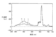
図2は、実施例1で得られた蛍光材料の波長250nmの紫外光を照射して励起したときの蛍光スペクトルの一例を示すグラフであり、縦軸はPL(Photo Luminescence)強度(a.u.)、横軸は波長(nm)である。図2中、aは15時間メカニカルミリング処理した場合、bは25時間メカニカルミリング処理した場合、cは35時間メカニカルミリング処理した場合をそれぞれ示している。図2に示す結果から、実施例1において、15時間、25時間、35時間のメカニカルミリング処理のいずれの場合にも、610nm付近に非常に強い蛍光を示す粉末が得られたことが分かる。
・ Rotation speed: 370 rpm
Pot and ball: made of ZrO 2 Ball:
なお、図2に示した蛍光スペクトルは、分光蛍光光度計(FP−6500、日本分光株式会社製)を用い、以下の条件で測定した。 The fluorescence spectrum shown in FIG. 2 was measured using a spectrofluorometer (FP-6500, manufactured by JASCO Corporation) under the following conditions.
・励起側バンド幅:3nm
・蛍光側バンド幅:3nm
・レスポンス:1sec
・感度:Medium
・データ取込間隔:1nm
・走査速度:100nm/min
<実施例2>
無アルカリガラス0.9705gと酸化テルビウム(Tb4O7)0.0298g、あるいはシリカ(SiO2)0.9705gと酸化テルビウム(Tb4O7)0.0298gを、実施例1と同様の条件で15時間メカニカルミリング処理して蛍光粉末を得、実施例1と同様の条件で蛍光スペクトルを測定した。図3は、実施例2で得られた蛍光材料の波長250nmの紫外光を照射して励起したときの蛍光スペクトルの一例を示すグラフであり、縦軸はPL(Photo Luminescence)強度(a.u.)、横軸は波長(nm)である。図3に示す結果から、540nm付近に非常に強い蛍光を示す粉末が得られたことが分かる。
Excitation side bandwidth: 3 nm
・ Fluorescence side bandwidth: 3nm
・ Response: 1 sec
・ Sensitivity: Medium
・ Data capture interval: 1 nm
Scanning speed: 100 nm / min
<Example 2>
0.9705 g of alkali-free glass and 0.0298 g of terbium oxide (Tb 4 O 7 ), or 0.9705 g of silica (SiO 2 ) and 0.0298 g of terbium oxide (Tb 4 O 7 ) under the same conditions as in Example 1. A fluorescent powder was obtained by mechanical milling for 15 hours, and a fluorescence spectrum was measured under the same conditions as in Example 1. FIG. 3 is a graph showing an example of a fluorescence spectrum when the fluorescent material obtained in Example 2 is excited by irradiation with ultraviolet light having a wavelength of 250 nm, and the vertical axis indicates PL (Photo Luminescence) intensity (au). .), The horizontal axis represents the wavelength (nm). From the results shown in FIG. 3, it can be seen that a powder having very strong fluorescence was obtained in the vicinity of 540 nm.
<実施例3>
無アルカリガラス0.961gとCeCl30.039gを実施例1と同様の条件で 時間メカニカルミリング処理して蛍光粉末を得、実施例1と同様の条件で蛍光スペクトルを測定した。図4は、実施例3で得られた蛍光材料の波長250nmの紫外光を照射して励起したときの蛍光スペクトルの一例を示すグラフであり、縦軸はPL(Photo Luminescence)強度(a.u.)、横軸は波長(nm)である。図4に示す結果から、370nm付近に非常に強い蛍光を示す粉末が得られたことが分かる。
<Example 3>
0.961 g of alkali-free glass and 0.039 g of CeCl 3 were subjected to a mechanical mechanical milling treatment under the same conditions as in Example 1 to obtain a fluorescent powder, and the fluorescence spectrum was measured under the same conditions as in Example 1. FIG. 4 is a graph showing an example of a fluorescence spectrum when the fluorescent material obtained in Example 3 is excited by irradiation with ultraviolet light having a wavelength of 250 nm, and the vertical axis indicates PL (Photo Luminescence) intensity (au). .), The horizontal axis represents the wavelength (nm). From the results shown in FIG. 4, it can be seen that a powder showing very strong fluorescence around 370 nm was obtained.
今回開示された実施の形態および実施例はすべての点で例示であって制限的なものではないと考えられるべきである。本発明の範囲は上記した説明ではなくて特許請求の範囲によって示され、特許請求の範囲と均等の意味および範囲内でのすべての変更が含まれることが意図される。 It should be understood that the embodiments and examples disclosed herein are illustrative and non-restrictive in every respect. The scope of the present invention is defined by the terms of the claims, rather than the description above, and is intended to include any modifications within the scope and meaning equivalent to the terms of the claims.
本発明によれば、不要となった液晶パネルから回収した無アルカリガラスの埋立地への投棄量を極力抑え、資源を有効に利用することができる。さらに、PDPおよびLEDなどへ使用可能な発光特性を有する安価な蛍光材料を製造することができる蛍光材料および蛍光材料の製造方法を提供することができる。 ADVANTAGE OF THE INVENTION According to this invention, the dumping amount to the landfill of the alkali free glass collect | recovered from the liquid crystal panel which became unnecessary can be suppressed as much as possible, and resources can be utilized effectively. Furthermore, the fluorescent material which can manufacture the cheap fluorescent material which has the light emission characteristic which can be used for PDP, LED, etc. and the manufacturing method of a fluorescent material can be provided.
1 液晶パネル、2a ガラス基板(カラーフィルタ側ガラス基板)、2b ガラス基板(TFT側ガラス基板)、3 シール樹脂体、4 液晶層、5 偏光板。 DESCRIPTION OF SYMBOLS 1 Liquid crystal panel, 2a Glass substrate (color filter side glass substrate), 2b Glass substrate (TFT side glass substrate), 3 Seal resin body, 4 Liquid crystal layer, 5 Polarizing plate.
Claims (6)
Priority Applications (3)
| Application Number | Priority Date | Filing Date | Title |
|---|---|---|---|
| JP2010002027A JP5535659B2 (en) | 2010-01-07 | 2010-01-07 | Fluorescent material and method for producing fluorescent material |
| PCT/JP2011/050030 WO2011083791A1 (en) | 2010-01-07 | 2011-01-05 | Fluorescent material and process for production of fluorescent material |
| CN201180005587XA CN102712841A (en) | 2010-01-07 | 2011-01-05 | Fluorescent material and process for production of fluorescent material |
Applications Claiming Priority (1)
| Application Number | Priority Date | Filing Date | Title |
|---|---|---|---|
| JP2010002027A JP5535659B2 (en) | 2010-01-07 | 2010-01-07 | Fluorescent material and method for producing fluorescent material |
Publications (3)
| Publication Number | Publication Date |
|---|---|
| JP2011140564A JP2011140564A (en) | 2011-07-21 |
| JP2011140564A5 JP2011140564A5 (en) | 2012-08-23 |
| JP5535659B2 true JP5535659B2 (en) | 2014-07-02 |
Family
ID=44305527
Family Applications (1)
| Application Number | Title | Priority Date | Filing Date |
|---|---|---|---|
| JP2010002027A Expired - Fee Related JP5535659B2 (en) | 2010-01-07 | 2010-01-07 | Fluorescent material and method for producing fluorescent material |
Country Status (3)
| Country | Link |
|---|---|
| JP (1) | JP5535659B2 (en) |
| CN (1) | CN102712841A (en) |
| WO (1) | WO2011083791A1 (en) |
Families Citing this family (2)
| Publication number | Priority date | Publication date | Assignee | Title |
|---|---|---|---|---|
| JP7113703B2 (en) * | 2018-08-31 | 2022-08-05 | 堺化学工業株式会社 | Manufacturing method of fluorescent glass and fluorescent glass |
| CN114956557B (en) * | 2022-06-10 | 2023-09-01 | 中山大学 | Method for preparing optical glass from waste glass and rare earth super-enriched plants |
Family Cites Families (7)
| Publication number | Priority date | Publication date | Assignee | Title |
|---|---|---|---|---|
| JPH07206499A (en) * | 1993-12-30 | 1995-08-08 | Nekusuto I:Kk | Production of luminous structural material |
| JPH11293238A (en) * | 1998-04-13 | 1999-10-26 | Kazuo Saito | Production of phosphor by utilizing glass powder particle |
| JP2003107197A (en) * | 2001-09-27 | 2003-04-09 | Fuji Photo Film Co Ltd | Radiological image conversion panel and its manufacturing method |
| EP1705160A4 (en) * | 2003-12-26 | 2009-05-06 | Asahi Glass Co Ltd | No alkali glass, method for production thereof and liquid crystalline display panel |
| JP2009280425A (en) * | 2008-05-21 | 2009-12-03 | Sharp Corp | Recycling method for non-alkali glass, and glass material obtained thereby |
| JP4952956B2 (en) * | 2008-12-24 | 2012-06-13 | 独立行政法人産業技術総合研究所 | Phosphor with crystallized metal oxide thin film |
| CN101586017B (en) * | 2009-05-18 | 2013-07-10 | 广东三和化工科技有限公司 | Storage light-emitting silicone sealant |
-
2010
- 2010-01-07 JP JP2010002027A patent/JP5535659B2/en not_active Expired - Fee Related
-
2011
- 2011-01-05 CN CN201180005587XA patent/CN102712841A/en active Pending
- 2011-01-05 WO PCT/JP2011/050030 patent/WO2011083791A1/en active Application Filing
Also Published As
| Publication number | Publication date |
|---|---|
| JP2011140564A (en) | 2011-07-21 |
| CN102712841A (en) | 2012-10-03 |
| WO2011083791A1 (en) | 2011-07-14 |
Similar Documents
| Publication | Publication Date | Title |
|---|---|---|
| Guo et al. | Enhanced white luminescence in mixed-valence Eu-doped BaAl2Si2O8 glass ceramics for W-LEDs | |
| Zaid et al. | Synthesis and characterization of low cost willemite based glass–ceramic for opto-electronic applications | |
| Ma et al. | Novel bifunctional YAG: Ce3+ based phosphor-in-glasses for WLEDs by Eu2+ enhancement | |
| Khaidir et al. | Exploring Eu3+-doped ZnO-SiO2 glass derived by recycling renewable source of waste rice husk for white-LEDs application | |
| Omar et al. | Europium doped low cost Zn2SiO4 based glass ceramics: A study on fabrication, structural, energy band gap and luminescence properties | |
| Xia et al. | Erosion mechanism of YAG: Ce3+ phosphor in bismuth borate glasses | |
| JP5535659B2 (en) | Fluorescent material and method for producing fluorescent material | |
| JP2009280425A (en) | Recycling method for non-alkali glass, and glass material obtained thereby | |
| CN102660281B (en) | Silica-coated orange-red phosphor and preparation method thereof | |
| Zaid et al. | Effect of heat treatment temperature to the crystal growth and optical performance of Mn3O4 doped α-Zn2SiO4 based glass-ceramics | |
| Wada et al. | Glass composition dependence of Eu3+ ion red fluorescence | |
| Monisha et al. | Judd-Ofelt analysis and luminescence characteristics of Eu3+ doped Nepheline (NaAlSiO4)-based glass ceramics for solid-state lighting applications | |
| JP2012116743A (en) | Method for manufacturing inorganic material using alkali-free glass as raw material | |
| Dan et al. | Influence of F− on the reduction process of Eu3+ to Eu2+ and optical properties of Eu3+/Eu2+–Er3+–Yb3+ co-doped niobate silicate glasses | |
| Vijayalakshmi et al. | Ravishing blue emission from Ce3+ activated lithium borate glasses for photonic applications | |
| Cheong et al. | Enhancing orange-reddish emission of the Sm3+-doped ZnO-B2O3-SLS glasses for the potential glass phosphor material | |
| Xu et al. | White light generation of glass ceramics containing Ba 2 LaF 7: Eu 2+, Tb 3+ and Sm 3+ nanocrystals | |
| JP6045917B2 (en) | Method for producing phosphorescent fluorescent material | |
| Zhou et al. | Color-tunable luminescence of Eu3+ in PbF2 embedded in oxyfluoroborate glass and its nanocrystalline glass | |
| Huang et al. | Optical properties of Eu2+-doped strontium borate glasses containing F− and Li+ ions | |
| JP2013142048A (en) | Method for manufacturing of zeolite using alkali-free glass as raw material, a-type zeolite, and molded product, water cleaning agent, soil modifying agent, and fertilizer holding agent using a-type zeolite | |
| JP2014133837A (en) | Light-storing fluorescent material | |
| Zhou et al. | Structure Controlled Luminescence Properties in Cu and/or Sn Doped Borate Glasses | |
| Lv et al. | Deep-UV-driven emission-tailorable borosilicate glasses by utilization of Sn2+ cations as versatile energy-transfer establishers | |
| CN104650882A (en) | Terbium/ytterbium-codoped alkali gallium tungstate up-conversion luminescent material, preparation method and application thereof |
Legal Events
| Date | Code | Title | Description |
|---|---|---|---|
| A521 | Request for written amendment filed |
Free format text: JAPANESE INTERMEDIATE CODE: A523 Effective date: 20120706 |
|
| A621 | Written request for application examination |
Free format text: JAPANESE INTERMEDIATE CODE: A621 Effective date: 20120706 |
|
| A521 | Request for written amendment filed |
Free format text: JAPANESE INTERMEDIATE CODE: A821 Effective date: 20120706 |
|
| A131 | Notification of reasons for refusal |
Free format text: JAPANESE INTERMEDIATE CODE: A131 Effective date: 20140107 |
|
| A521 | Request for written amendment filed |
Free format text: JAPANESE INTERMEDIATE CODE: A523 Effective date: 20140225 |
|
| TRDD | Decision of grant or rejection written | ||
| A01 | Written decision to grant a patent or to grant a registration (utility model) |
Free format text: JAPANESE INTERMEDIATE CODE: A01 Effective date: 20140401 |
|
| A61 | First payment of annual fees (during grant procedure) |
Free format text: JAPANESE INTERMEDIATE CODE: A61 Effective date: 20140423 |
|
| R150 | Certificate of patent or registration of utility model |
Ref document number: 5535659 Country of ref document: JP Free format text: JAPANESE INTERMEDIATE CODE: R150 |
|
| S531 | Written request for registration of change of domicile |
Free format text: JAPANESE INTERMEDIATE CODE: R313531 |
|
| S111 | Request for change of ownership or part of ownership |
Free format text: JAPANESE INTERMEDIATE CODE: R313117 |
|
| R350 | Written notification of registration of transfer |
Free format text: JAPANESE INTERMEDIATE CODE: R350 |
|
| R350 | Written notification of registration of transfer |
Free format text: JAPANESE INTERMEDIATE CODE: R350 |
|
| LAPS | Cancellation because of no payment of annual fees |