JP5534636B2 - Motor and drive device - Google Patents
Motor and drive device Download PDFInfo
- Publication number
- JP5534636B2 JP5534636B2 JP2007278965A JP2007278965A JP5534636B2 JP 5534636 B2 JP5534636 B2 JP 5534636B2 JP 2007278965 A JP2007278965 A JP 2007278965A JP 2007278965 A JP2007278965 A JP 2007278965A JP 5534636 B2 JP5534636 B2 JP 5534636B2
- Authority
- JP
- Japan
- Prior art keywords
- yoke
- magnetic pole
- magnet
- thin
- angle
- Prior art date
- Legal status (The legal status is an assumption and is not a legal conclusion. Google has not performed a legal analysis and makes no representation as to the accuracy of the status listed.)
- Expired - Fee Related
Links
Images


Classifications
-
- H—ELECTRICITY
- H02—GENERATION; CONVERSION OR DISTRIBUTION OF ELECTRIC POWER
- H02K—DYNAMO-ELECTRIC MACHINES
- H02K37/00—Motors with rotor rotating step by step and without interrupter or commutator driven by the rotor, e.g. stepping motors
- H02K37/10—Motors with rotor rotating step by step and without interrupter or commutator driven by the rotor, e.g. stepping motors of permanent magnet type
- H02K37/12—Motors with rotor rotating step by step and without interrupter or commutator driven by the rotor, e.g. stepping motors of permanent magnet type with stationary armatures and rotating magnets
- H02K37/14—Motors with rotor rotating step by step and without interrupter or commutator driven by the rotor, e.g. stepping motors of permanent magnet type with stationary armatures and rotating magnets with magnets rotating within the armatures
-
- H—ELECTRICITY
- H02—GENERATION; CONVERSION OR DISTRIBUTION OF ELECTRIC POWER
- H02K—DYNAMO-ELECTRIC MACHINES
- H02K1/00—Details of the magnetic circuit
- H02K1/06—Details of the magnetic circuit characterised by the shape, form or construction
- H02K1/12—Stationary parts of the magnetic circuit
- H02K1/14—Stator cores with salient poles
- H02K1/145—Stator cores with salient poles having an annular coil, e.g. of the claw-pole type
-
- Y—GENERAL TAGGING OF NEW TECHNOLOGICAL DEVELOPMENTS; GENERAL TAGGING OF CROSS-SECTIONAL TECHNOLOGIES SPANNING OVER SEVERAL SECTIONS OF THE IPC; TECHNICAL SUBJECTS COVERED BY FORMER USPC CROSS-REFERENCE ART COLLECTIONS [XRACs] AND DIGESTS
- Y10—TECHNICAL SUBJECTS COVERED BY FORMER USPC
- Y10T—TECHNICAL SUBJECTS COVERED BY FORMER US CLASSIFICATION
- Y10T29/00—Metal working
- Y10T29/49—Method of mechanical manufacture
- Y10T29/49002—Electrical device making
- Y10T29/49009—Dynamoelectric machine
Description
本発明は、2相PM型ステップモータに関する。 The present invention relates to a two-phase PM type step motor.
現在、コイルによって励磁されたヨークとマグネットの間の相互作用によって回転運動を行うステップモータが実用化されている(特許文献1参照)。 Currently, a step motor that performs a rotational motion by the interaction between a yoke and a magnet excited by a coil has been put into practical use (see Patent Document 1).
また、カメラなどに用いられるレンズ駆動装置として、スパイラル着磁されたマグネットとスパイラル着磁に沿ったヨークの間の相互作用によってレンズを直進駆動させているものがある(特許文献2参照)。
上記特許文献1に開示されているステップモータでは、ヨークをプレス加工によって生産することが行われている。すなわち、平板を打ち抜き加工することにより平面上に磁極歯形状を作成した後、磁極歯を立ち曲げることによりヨークが生産されていた。
In the step motor disclosed in
しかし、モータの外径を変えずにマグネットとの対向面積を向上させるために磁極歯を軸方向に長くしようとすると、打ち抜き加工の工程で平面上に磁極歯形状が収まりきらなくなるため、立ち曲げ時に絞り加工などにより磁極歯を伸ばす工程が必要になる。 However, if the magnetic pole teeth are made longer in the axial direction in order to improve the area facing the magnet without changing the outer diameter of the motor, the shape of the magnetic pole teeth will not be able to fit on the plane in the punching process. Sometimes it is necessary to extend the magnetic pole teeth by drawing or the like.
図10はプレス加工によって生産されるヨークを示した図である。図10において、A−1,A−2は打ち抜き加工後のヨーク、B−1,B−2は立ち曲げ加工後のヨークを示している。A−1における磁極歯高さhは内周半径Rより小さくなる。したがって、B−2における磁極歯高さh’も内周半径Rより小さくなる。絞り加工によってh’を大きくすることも可能であるが、その分、生産コストが高くなる。また、絞り加工を行ってもh’を極端に大きくすることはできず、h’の寸法には限界がある。 FIG. 10 is a view showing a yoke produced by press working. In FIG. 10, A-1 and A-2 indicate yokes after punching, and B-1 and B-2 indicate yokes after standing bending. The magnetic pole tooth height h in A-1 is smaller than the inner peripheral radius R. Therefore, the magnetic pole tooth height h 'in B-2 is also smaller than the inner peripheral radius R. Although it is possible to increase h ′ by drawing, the production cost increases accordingly. Further, even if drawing is performed, h ′ cannot be extremely increased, and there is a limit to the dimension of h ′.
したがって、軸方向に長い磁極歯をプレス加工によって安価に生産することは難しく、生産コストが高いという問題点があった。 Therefore, it is difficult to inexpensively produce magnetic pole teeth that are long in the axial direction by press working, and there is a problem that the production cost is high.
さらに、1つのコイルによって励磁される2つのヨークが別部材で構成されているため、2つのヨークがもつ磁極歯の位置関係が組立精度によってばらつき、安定した性能が出ないという問題点があった。 Furthermore, since the two yokes excited by one coil are composed of different members, the positional relationship between the magnetic pole teeth of the two yokes varies depending on the assembly accuracy, and there is a problem in that stable performance cannot be obtained. .
また、上記特許文献2に開示されているレンズ駆動装置では、磁極歯がマグネットの着磁部に沿ってスパイラル形状に延出しており、磁極歯の長さが比較的長い。さらに、磁極歯が所定の角度を持って延出しているため、打ち抜き加工の工程で隣り合う磁極歯同士が干渉しやすい。
In the lens driving device disclosed in
図11はプレス加工によって生産される磁極歯が傾いたヨークを示した図である。図11において、A−1,A−2は打ち抜き加工後のヨーク、B−1,B−2は立ち曲げ加工後のヨークを示している。A−1における磁極歯の長さL、磁極歯の傾きθによっては磁極歯の先端が隣の磁極歯に干渉してしまうので、設計の自由度が限られる。また、傾きθを保ったまま立ち曲げ加工を行うことは難しい。 FIG. 11 is a view showing a yoke with inclined magnetic pole teeth produced by pressing. In FIG. 11, A-1 and A-2 indicate yokes after punching, and B-1 and B-2 indicate yokes after standing bending. Depending on the length L of the magnetic pole tooth and the inclination θ of the magnetic pole tooth in A-1, the tip of the magnetic pole tooth interferes with the adjacent magnetic pole tooth, so the degree of freedom in design is limited. Moreover, it is difficult to perform standing bending while maintaining the inclination θ.
以上のことから、ヨークをプレス加工によって生産することは難しく、安定した性能を有するモータに適用可能なヨークを生産しようとすると、生産コストが高くなるという問題点があった。 From the above, it is difficult to produce the yoke by press working, and there has been a problem that production cost increases when it is attempted to produce a yoke applicable to a motor having stable performance.
さらに、1つのコイルによって励磁される2つのヨークが別部材で構成されているため、2つのヨークがもつ磁極歯の位置関係が組立精度によってばらつき、安定した性能が出ないという問題点もあった。 Furthermore, since the two yokes excited by one coil are composed of different members, the positional relationship between the magnetic pole teeth of the two yokes varies depending on the assembly accuracy, and there is a problem that stable performance does not appear. .
そこで本発明の目的は、低コストで安定した性能を有するモータおよび駆動装置を提供することを目的とする。 SUMMARY OF THE INVENTION An object of the present invention is to provide a motor and a driving device having stable performance at low cost.
上記課題を解決するために、本発明のモータは、外周面が周方向に分割して着磁された円筒形状のマグネットと、前記マグネットに対向する円筒形状のヨークと、前記ヨークを励磁するコイルと、前記ヨークの内周に形成され、前記マグネットの軸方向に沿って延出し、前記コイルによって励磁される第1の磁極部と、前記ヨークの内周に形成され、前記マグネットの軸方向に沿って延出し、前記コイルによって前記第1の磁極部とは異なる極に励磁される第2の磁極部とを有し、前記ヨークの周方向に対して第1の角度だけ傾いて延出する溝を前記ヨークの内周に形成することで、前記第1の磁極部と前記第2の磁極部とを連結する第1の薄肉部を形成し、前記ヨークの周方向に対して第2の角度だけ傾いて延出する溝を前記ヨークの内周に形成することで、前記第1の磁極部と前記第2の磁極部とを連結する第2の薄肉部を形成し、前記第1の角度と前記第2の角度とは互いに異なり、前記ヨークの周方向に前記第1の薄肉部と前記第2の薄肉部とを交互に形成することを特徴とする。 In order to solve the above-described problems, a motor according to the present invention includes a cylindrical magnet whose outer peripheral surface is divided and magnetized in the circumferential direction, a cylindrical yoke facing the magnet, and a coil that excites the yoke. And formed on the inner periphery of the yoke, extending along the axial direction of the magnet and excited by the coil, and formed on the inner periphery of the yoke, in the axial direction of the magnet. And a second magnetic pole portion that is excited by the coil to a pole different from the first magnetic pole portion, and extends at a first angle with respect to the circumferential direction of the yoke. By forming a groove in the inner periphery of the yoke, a first thin portion that connects the first magnetic pole portion and the second magnetic pole portion is formed, and a second thin portion is formed in the circumferential direction of the yoke. A groove extending at an angle is provided on the inner circumference of the yoke. By forming the first to form a second thin wall portion which connects the magnetic pole portion and the second magnetic pole portion, unlike each other and said first angle and the second angle, the yoke and the circumferentially first thin portion and said second thin portion, characterized that you are alternately formed.
本発明によれば、低コストで安定した性能を有するモータおよび駆動装置を提供することが可能となる。 According to the present invention, it is possible to provide a motor and a driving device having stable performance at low cost.
以下、本発明に係る一実施形態について図面を参照して詳細に説明する。 Hereinafter, an embodiment according to the present invention will be described in detail with reference to the drawings.
なお、以下に説明する実施形態は、本発明を実現するための一例であり、本発明が適用される装置の構成や各種条件によって適宜修正又は変更されるべきものであり、本発明は以下の実施形態に限定されるものではない。 The embodiment described below is an example for realizing the present invention, and should be appropriately modified or changed according to the configuration and various conditions of the apparatus to which the present invention is applied. It is not limited to the embodiment.
<第1の実施形態>
(モータの構成の説明)
図1は第1の実施形態に係るモータを示す分解斜視図、図2は第1の実施形態に係るモータを示す軸方向断面図である。
<First Embodiment>
(Explanation of motor configuration)
FIG. 1 is an exploded perspective view showing a motor according to the first embodiment, and FIG. 2 is an axial sectional view showing the motor according to the first embodiment.
図1、図2において、101は円筒形状で外周面が周方向に分割されて着磁されたマグネットである。本実施形態では8極の着磁部を有するマグネットを例にとって説明するが、極数によって本発明が限定されるものではない。
1 and 2,
102は円筒形状のコアであり、外周がマグネット101の内周部と嵌合または接着され、一体に固定されている。
103は軸であり、コア102の内周部と軸103の外周の一部が嵌合または接着され、一体に固定されている。また、外周の一部が後述する第1の軸受113、第2の軸受123と摺動し、軸103が回転可能に固定されている。また、端部は後述する第1のステータ110または第2のステータ120から軸方向に露出しており、回転運動により発生する動力を外部に取り出せるように構成されている。
マグネット101、コア102、軸103によってロータ100が構成されている。
A
111は軟磁性材料からなる第1のヨークであり、円筒部111a、フランジ部111b、円筒部111aの内周に軸方向に延出して形成される磁極部111c、ねじ形状に形成される薄肉部111dを有する。磁極部111cの径方向の厚さをt1、薄肉部111dの径方向の厚さをt2とすると、t1>t2となるように寸法が決定されている。また、薄肉部の径方向の厚さは、フランジ部111bの軸方向の厚さ、後述する第1のケース112の径方向の厚さ・軸方向の厚さに比べて薄くなるように形成されることが望ましい。薄肉部がこのように形成されることが望ましい理由を以下に述べる。
コイルに流す電流を増やしていくと、磁界が強くなり、他の磁路に比べて断面積が小さい部分、本実施形態における、薄肉部111dで最初に磁束飽和が起こり、磁束が空気中に漏れることになる。本実施形態のモータでは、薄肉部において空気中に漏れた磁束と、磁石との相互作用によりモータの回転力を得ている。もし仮に、ケース112の径方向厚さが、薄肉部111dより薄かった(断面積が小さい)としたら、先にケースで磁束飽和が起こってしまうため、磁束飽和による損失を考えると効率がよくないので、このような構成をとることが望ましい。
As the current flowing through the coil is increased, the magnetic field becomes stronger and the magnetic flux saturation first occurs in the thin-walled portion 111d in the present embodiment where the cross-sectional area is small compared to other magnetic paths, and the magnetic flux leaks into the air. It will be. In the motor of the present embodiment, the rotational force of the motor is obtained by the interaction between the magnetic flux leaking into the air at the thin wall portion and the magnet. If the thickness of the
磁極部111c、薄肉部111dの形状に関しては後述する。
The shapes of the
112はカップ形状で軟磁性材料からなる第1のケースであり、開口部112a、曲げ部112b、穴部112cを有する。開口部112aは第1のヨークのフランジ部111bと軸方向に当接して固定されることで、第1のヨーク111と第1のケース112との軸方向の位置関係が決定される。曲げ部112b内周は第1のヨークの円筒部111a外周と嵌合し、第1のヨーク111と第1のケース112との径方向の位置関係が決定される。
さらに、穴部112cが後述する第1の軸受113の外周部と嵌合し、第1の軸受113との径方向の位置関係が決定されるとともに、軸受113のつば部と当接し、第1の軸受113と軸方向の位置関係が決定される。
Further, the
また、本実施形態とは異なり、開口部112aの内周と第1のヨークのフランジ部111bの外周を嵌合させて、第1のヨーク111と第1のケース112との径方向の位置関係を決定するように構成してもよい。また、本実施形態とは異なり、第1のヨークの円筒部111aの端部を第1のケース112の一部に軸方向に当接して固定することで、第1のヨーク111と第1のケース112との軸方向の位置関係を決定するように構成してもよい。
Also, unlike the present embodiment, the inner periphery of the opening 112a and the outer periphery of the flange portion 111b of the first yoke are fitted together, and the radial positional relationship between the
113は第1の軸受であり、前述したように第1のケース112に固定されるとともに軸103と摺動可能に配置されている。114は非導電性材料からなる第1のボビンである。115は第1のコイルであり、第1のボビン114に巻回されている。
第1のヨーク111、第1のケース112、第1の軸受113、第1のボビン114、第1のコイル115によって第1のステータ110が構成されている。
The first stator 110 is configured by the
第2のヨーク121、第2のケース122、第2の軸受123、第2のボビン124、第2のコイル125に関しても第1のステータ110を構成する各部と同様であるので説明は省略する。第2のヨーク121、第2のケース122、第2の軸受123、第2のボビン124、第2のコイル125によって第2のステータ120が構成されている。
Since the
(磁極歯形状の説明)
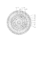
図3は第1の実施形態に係るモータのヨーク構造を示す展開図である。ここでは、第1のヨーク111と第2のヨーク121が実際に組み立てられる時の位置関係をもって、各ヨークの円筒部を内周側から見た展開図が示されている。
(Description of magnetic pole tooth shape)
FIG. 3 is a development view showing the yoke structure of the motor according to the first embodiment. Here, a development view in which the cylindrical portion of each yoke is viewed from the inner peripheral side is shown with a positional relationship when the
図3において、まず第1のヨーク111の形状から説明する。
In FIG. 3, the shape of the
111c(1)は、周方向に並んだ三角形状の複数の磁極歯を有する第1の磁極部であり、マグネット101の軸方向に沿って延出し第1のコイルによって一方の極に励磁される。各磁極歯は、第1のヨークのフランジ部111bとは逆の端面を底辺として、第1のヨークのフランジ部111b端面へ向かって延出している。個数N個の磁極歯が所定の位相間隔2Pをとって形成されている。ここで、マグネット101の極数Mとすると、N、2Pは以下の式で表される。
N=M/2,2P=2×360°/M
マグネットの極数を8極とした本実施形態では、磁極歯の個数は4、磁極歯の位相間隔は90°となる。
111c (1) is a first magnetic pole portion having a plurality of triangular magnetic pole teeth arranged in the circumferential direction, and extends along the axial direction of the
N = M / 2, 2P = 2 × 360 ° / M
In the present embodiment in which the number of magnet poles is 8, the number of magnetic pole teeth is 4, and the phase interval of the magnetic pole teeth is 90 °.
111c(2)は、周方向に並んだ三角形状の複数の磁極歯を有する第2の磁極部であり、マグネット101の軸方向に沿って延出し第2のコイルによって一方の極に励磁される。各磁極歯は、第1のヨークのフランジ部111b端面を底辺として、第1のヨークのフランジ部111bとは逆の端面へ向かって延出している。磁極歯の個数、磁極歯の位相間隔は111c(1)と同様である。
111 c (2) is a second magnetic pole portion having a plurality of triangular magnetic pole teeth arranged in the circumferential direction, and extends along the axial direction of the
磁極部111c(1)と111c(2)は所定の位相差を持って形成されており、位相差Pは以下の式で表される。
P=360°/M
マグネットの極数を8極とした本実施形態では、磁極部の位相差は45°となる。
The
P = 360 ° / M
In the present embodiment in which the number of poles of the magnet is 8, the phase difference of the magnetic pole portion is 45 °.
また、円筒部111aの軸方向高さをh1、磁極部111cの軸方向高さをh2、フランジ部111bの軸方向高さをh3とすると、以下の関係を持つように磁極歯が形成されることが望ましい。
h1>h2,h1−h2>h3
111d(1)は、円周方向から所定の角度α1、所定の幅w1を持って形成される薄肉部である。形状は多条ねじ形状となっており、条数Jは以下の式で表される。
J=M/2
マグネットの極数を8極とした本実施形態では、条数は4となる。
Further, when the axial height of the cylindrical portion 111a is h1, the axial height of the
h1> h2, h1-h2> h3
111d (1) is a thin portion formed with a predetermined angle α1 and a predetermined width w1 from the circumferential direction. The shape is a multi-threaded shape, and the number J is represented by the following formula.
J = M / 2
In this embodiment in which the number of magnet poles is eight, the number of stripes is four.
111d(2)は、円周方向から所定の角度α2、所定の幅w2を持って形成される薄肉部である。形状は多条ねじ形状となっており、条数は111d(1)と同様である。 111d (2) is a thin portion formed with a predetermined angle α2 and a predetermined width w2 from the circumferential direction. The shape is a multiple thread shape, and the number of threads is the same as 111d (1).
薄肉部111d(1)と111d(2)によって、磁極部111c(1)と111c(2)の形状が決定される。
The shapes of the
また、薄肉部111d(1)と111d(2)はα1とα2が以下の関係を持つように形成されることが望ましい。
α1+α2=180°,tanα1=h1/P
本実施形態では薄肉部111d(1)と111d(2)が連続して形成されているが、磁極歯111cによって分断されていてもよいし、薄肉部111dの一部が円筒部111aの径方向に貫通している構成でもよい。
Further, it is desirable that the thin portions 111d (1) and 111d (2) are formed so that α1 and α2 have the following relationship.
α1 + α2 = 180 °, tan α1 = h1 / P
In the present embodiment, the thin portions 111d (1) and 111d (2) are formed continuously, but may be divided by the
なお、薄肉部111d(1)と111d(2)は、多条ねじ切り加工によって作成可能である。 The thin portions 111d (1) and 111d (2) can be created by multi-thread threading.
作成手順としては、まず、リード角がα1、条数Jのタップ1と、リード角がα2、条数Jのタップ2を用意する。そして、円筒部111aとフランジ部111bを有するヨークに対し、円筒部111a内周にタップ1によって薄肉部111d(1)を作成する。その後、円筒部111b内周にタップ2によって薄肉部111d(2)を作成することで、本実施形態のヨーク形状が作成可能である。つまり、薄肉部は2種類の異なるタップにより形成されている。
As a preparation procedure, first, a
また、フランジ部111bを別部材とし、円筒部111aにねじ切り加工を行った後、フランジ部111bを溶接などにより固着してもよいし、円筒部111aにねじ切り加工を行った後、外周の切削加工などによりフランジ部111bを形成してもよい。 Further, the flange portion 111b may be a separate member, and after the threading process is performed on the cylindrical portion 111a, the flange portion 111b may be fixed by welding or the like, or after the threading processing is performed on the cylindrical portion 111a, the outer periphery is cut. For example, the flange portion 111b may be formed.
また、タップの歯形状とリード角を変更することで、磁極部111cと薄肉部111dの形状は自由に変更可能である。例えば、磁極部111cの軸方向高さh2を自由に変更可能である。
Moreover, the shape of the
上記にあげたいずれの手順でヨークの形状を作成しても、第1の磁極部と第2の磁極部は、第1の磁極部または第2の磁極部と比べて径方向の厚さが小さい薄肉部で連結されることになる。なお、この構成については、後述する第2のヨーク121における、第3の磁極部と第4の磁極部についても同様である。
Regardless of the procedure described above, the first magnetic pole part and the second magnetic pole part have a radial thickness that is greater than that of the first magnetic pole part or the second magnetic pole part. It will be connected by a small thin part. This configuration is the same for the third magnetic pole part and the fourth magnetic pole part in the
第2のヨーク121の形状も同様であるので、説明は省略する。第1のヨーク111と第2のヨーク121は、第1のヨークの磁極部111cと第2のヨークの磁極部121cが所定の位相差を持つように組み立てられており、位相差P/2は以下の式で表される。
P/2=360°/(2×M)
マグネットの極数を8極とした本実施形態では、位相差P/2は22.5°となる。
Since the shape of the
P / 2 = 360 ° / (2 × M)
In this embodiment in which the number of poles of the magnet is eight, the phase difference P / 2 is 22.5 °.
(動作の説明)
図4は第1の実施形態に係るモータを示す径方向の断面図である。
(Description of operation)
FIG. 4 is a radial sectional view showing the motor according to the first embodiment.
まず、第1のステータ110の動作について説明する。 First, the operation of the first stator 110 will be described.
第1のコイル115に電流を流すとコイル導線方向を中心とした磁界が発生し、それに伴い、第1のヨークの円筒部111a、第1のヨークのフランジ部111b、第1のケース112の内部に磁束が発生し、磁路が形成される。さらに大きな電流を流し、第1のヨーク111と第1のケース112の内部に発生する磁束を大きくすると、磁束方向の断面積が小さい場所で磁束の飽和が生じ、磁束が空気中に漏れる。
When a current is passed through the
本実施形態では、第1のヨーク磁極部111cの径方向の厚さ、第1のヨークフランジ部111bの軸方向の厚さ、第1のケース112の径方向・軸方向の厚さに比べて第1のヨーク薄肉部111dの径方向の厚さが薄い。そのため、第1のヨーク薄肉部111dが、最も磁束飽和が発生しやすい場所となり、磁極部111c(1)と磁極部111c(2)の間で磁束が空気中に漏れる。
In the present embodiment, the radial thickness of the first yoke
例えば、図3、図4において、第1のコイル115に充分な電流を流すと、薄肉部111d(1)で磁束飽和が生じ、矢印Aの方向に磁束が漏れ、磁極部111c(1)がN極、磁極部111c(2)がS極に励磁されることになる。このとき発生する漏れ磁束とマグネット101による磁界の相互作用により、ロータ100に回転方向の力が発生する。ロータ100は回転方向の力を受けて所定の角度だけ回転する。
For example, in FIG. 3 and FIG. 4, when a sufficient current is passed through the
第2のステータ120に関しても同様であるので、説明は省略する。
Since the same applies to the
以上説明したように、第1のコイル115と第2のコイル125の通電方向を順次切り替えることにより、特許文献1に挙げた2相PM型ステップモータと同様に回転運動が可能となる。
As described above, by sequentially switching the energization directions of the
このように、本実施形態に記載のモータは、ねじ切り加工によって磁極部を作成することが可能なため、プレス加工によって磁極部を作成するよりも、低コストでモータを提供することが可能である。 As described above, since the motor described in the present embodiment can create the magnetic pole part by threading, it is possible to provide the motor at a lower cost than creating the magnetic pole part by pressing. .
また、プレス加工で作成する従来のヨークは磁極部の高さに制限があったが、本実施形態のモータではタップの歯形状とリード角を変えることにより磁極部の形状を自由に変更可能である。そのため、軸方向に長い磁極歯をもつヨークを容易に作成でき、低コストで高トルクなモータを提供することが可能である。 In addition, the conventional yoke created by press working has a limit on the height of the magnetic pole part, but in the motor of this embodiment, the shape of the magnetic pole part can be freely changed by changing the tooth shape of the tap and the lead angle. is there. Therefore, a yoke having long magnetic pole teeth in the axial direction can be easily produced, and a low-cost and high-torque motor can be provided.
また、従来は1つのコイルによって励磁される1対の磁極部が別部材で構成されていたのに対し、本実施形態に記載のモータでは1対の磁極部を一体で作成するので、磁極歯間の位置関係が精度よく決定され、変形も起こりにくい。そのため、安定した性能を有するモータを提供することが可能である。 Conventionally, a pair of magnetic pole portions excited by one coil are formed of separate members, but the motor described in the present embodiment integrally forms a pair of magnetic pole portions. The positional relationship between them is accurately determined, and deformation is unlikely to occur. Therefore, it is possible to provide a motor having stable performance.
なお、本実施形態は、2相のステップモータについて記載したが、これに限られるわけでなく、2相以上のステップモータについても適応可能である。 In addition, although this embodiment described about the two-phase step motor, it is not necessarily restricted to this, It can apply also to the two-phase or more step motor.
<第2の実施形態>
(駆動装置の構成の説明)
図5は第2の実施形態に係る駆動装置を示す分解斜視図、図6は第2の実施形態に係る駆動装置を示す軸方向の断面図である。
<Second Embodiment>
(Description of the configuration of the driving device)
FIG. 5 is an exploded perspective view showing the drive device according to the second embodiment, and FIG. 6 is an axial sectional view showing the drive device according to the second embodiment.
図5、図6において、201は円筒形状で外周面がスパイラル状に着磁されたマグネットである。201aはN極に着磁された着磁部、201bはS極に着磁された着磁部である。本実施形態では8極の着磁部を有するマグネットを例にとって説明するが、極数によって本発明が限定されるものではない。
5 and 6,
202は、ガイド部としての、円筒状のチューブであり、外周がマグネット201の内周と嵌合または接着され、一体的に固定されている。また、内周は後述するガイド軸231の外周と摺動可能に嵌合しており、ガイド軸231は、チューブ202を回転軸と平行な方向に可動可能に支持する。
マグネット201とチューブ202によって可動部200が構成されている。可動部200は後述するガイド軸231によって径方向の移動を規制されている。また、可動部200は不図示の回転止めにより回転方向の移動を規制されている。そのため、可動部200は回転軸に平行な方向にのみ可動可能に保持されている。
The
211は軟磁性材料からなる第1のヨークであり、円筒部211a、フランジ部211b、円筒部211aの内周にマグネット着磁部に沿って対向するように形成される磁極部211c、ねじ形状に形成される薄肉部211dを有する。磁極部211cの径方向の厚さをt1、薄肉部211dの径方向の厚さをt2とすると、t1>t2となるように寸法が決定されている。また、薄肉部の径方向の厚さは、フランジ部111bの軸方向の厚さ、後述する第1のケース212の径方向の厚さ・軸方向の厚さに比べて薄くなるように形成されることが望ましい。薄肉部がこのように形成されることが望ましい理由は、第1の実施形態にて説明した理由と同様である。
211 is a first yoke made of a soft magnetic material, and includes a cylindrical portion 211a, a
磁極部211c、薄肉部211dの形状に関しては後述する。
The shapes of the
212はカップ形状で軟磁性材料からなる第1のケースであり、開口部212a、穴部212bを有する。
開口部212aは第1のヨークのフランジ部211bと軸方向に当接して固定されることで、第1のヨーク211と第1のケース212との軸方向の位置関係が決定される。穴部212b内周は第1のヨークの円筒部211a外周と嵌合し、第1のヨーク211と第1のケース212との径方向の位置関係が決定される。
The opening 212a is fixed in contact with the
また、本実施形態とは異なり、開口部212a内周と第1のヨークのフランジ部211b外周を嵌合させて、第1のヨーク211と第1のケース212との径方向の位置関係を決定するように構成してもよい。また、本実施形態とは異なり、第1のヨークの円筒部211a端部を第1のケース212の一部に軸方向に当接して固定することで、第1のヨーク211と第1のケース212との軸方向の位置関係を決定するように構成してもよい。
Unlike the present embodiment, the inner periphery of the opening 212a and the outer periphery of the
213は非導電性材料からなる第1のボビンである。214は第1のコイルであり、第1のボビン213に巻回されている。
第1のヨーク211、第1のケース212、第1のボビン113、第1のコイル114によって第1のステータ210が構成されている。
A
第2のヨーク221、第2のケース222、第2のボビン223、第2のコイル224に関しても第1のステータ210を構成する各部と同様であるので説明は省略する。第2のヨーク221、第2のケース222、第2のボビン223、第2のコイル224によって第2のステータ220が構成されている。
The
(磁極歯形状の説明)
図7は第2の実施形態に係る駆動装置のヨーク構造を示す展開図である。ここでは、第1のヨーク211と第2のヨーク221が実際に組み立てられる時の位置関係をもって、各ヨークの円筒部を内周側から見た展開図が示されている。
(Description of magnetic pole tooth shape)
FIG. 7 is a development view showing the yoke structure of the driving apparatus according to the second embodiment. Here, a development view in which the cylindrical portion of each yoke is viewed from the inner peripheral side is shown with a positional relationship when the
図7において、まず第1のヨーク211の形状から説明する。
In FIG. 7, first, the shape of the
211c(1)は、周方向に並んだ三角形状の複数の磁極歯を有する第1の磁極部である。各磁極歯は、円筒部211aのフランジ部211b側端面を底辺として、周方向から所定の角度α0を持ってマグネット101の着磁部に沿うように延出している。ここで、α0は磁極歯の周方向の中心を結んだ直線が周方向となす角を表している。マグネット101の着磁部の周方向に対する角度をθとしたとき、α0は次の関係を持つように決定されることが望ましい。
α0=θ
第1の磁極部211c(1)は、個数N個の磁極歯が所定の位相間隔2Pをとって形成されている。ここで、マグネット101の極数Mとすると、N、2Pは以下の式で表される。
N=M/2,2P=2×360°/M
マグネットの極数を8極とした本実施形態では、磁極歯の個数は4、磁極歯の位相間隔は90°となる。
211c (1) is a first magnetic pole portion having a plurality of triangular magnetic pole teeth arranged in the circumferential direction. Each magnetic pole tooth extends along the magnetized portion of the
α0 = θ
The first
N = M / 2, 2P = 2 × 360 ° / M
In the present embodiment in which the number of magnet poles is 8, the number of magnetic pole teeth is 4, and the phase interval of the magnetic pole teeth is 90 °.
211c(2)は、周方向に並んだ三角形状の複数の磁極歯を有する第2の磁極部である。各磁極歯は、円筒部211aのフランジ部211bとは逆側の端面を底辺として、周方向から所定の角度α0を持ってマグネット101の着磁部に沿うように延出している。磁極歯の個数、磁極歯の位相間隔は211c(1)と同様である。
211c (2) is a second magnetic pole portion having a plurality of triangular magnetic pole teeth arranged in the circumferential direction. Each magnetic pole tooth extends along the magnetized portion of the
磁極は列211c(1)と211c(2)は所定の位相差を持って形成されており、位相差Pは以下の式で表される。
P=360°/M
マグネットの極数を8極とした本実施形態では、磁極部の位相差は45°となる。
The
P = 360 ° / M
In the present embodiment in which the number of poles of the magnet is 8, the phase difference of the magnetic pole portion is 45 °.
また、円筒部111aの軸方向高さをh1、磁極部211cの軸方向高さをh2、フランジ部211bの軸方向高さをh3とすると、以下の関係を持つように磁極歯が形成されることが望ましい。
h1>h2,h1−h2>h3
211d(1)は、円周方向から所定の角度α1、所定の幅w1を持って形成される薄肉部である。形状は多条ねじ形状となっており、条数Jは以下の式で表される。
J=M/2
マグネットの極数を8極とした本実施例では、条数は4となる。
Further, when the axial height of the cylindrical portion 111a is h1, the axial height of the
h1> h2, h1-h2> h3
211d (1) is a thin part formed with a predetermined angle α1 and a predetermined width w1 from the circumferential direction. The shape is a multi-threaded shape, and the number J is represented by the following formula.
J = M / 2
In this embodiment in which the number of poles of the magnet is 8, the number of strips is 4.
211d(2)は、円周方向から所定の角度α2、所定の幅w2を持って形成される薄肉部である。形状は多条ねじ形状となっており、条数は211d(1)と同様である。 211d (2) is a thin part formed with a predetermined angle α2 and a predetermined width w2 from the circumferential direction. The shape is a multi-threaded shape, and the number of threads is the same as 211d (1).
薄肉部211d(1)と211d(2)によって、磁極部211c(1)と211c(2)の形状が決定される。
The shapes of the
また、薄肉部211d(1)と211d(2)はα1とα2が以下の関係を持つように形成されることが望ましい。
α1≦α0=θ≦α2
本実施形態では薄肉部211d(1)と211d(2)が連続して形成されているが、磁極歯211cによって分断されていてもよいし、薄肉部211dの一部が円筒部111aの径方向に貫通している構成でもよい。
The
α1 ≦ α0 = θ ≦ α2
In the present embodiment, the
薄肉部211d(1)と211d(2)は、多条ねじ切り加工によって作成可能である。
The
まず、リード角がα1、条数Jのタップ1と、リード角がα2、条数Jのタップ2を用意する。そして、円筒部211aとフランジ部211bを有するヨークに対し、円筒部211a内周にタップ1によって薄肉部211d(1)を作成する。その後、円筒部211b内周にタップ2によって薄肉部211d(2)を作成することで、本実施形態のヨーク形状が作成可能である。また、フランジ部211bを別部材とし、円筒部211aにねじ切り加工を行った後、フランジ部211bを溶接などにより固着してもよいし、円筒部211aにねじ切り加工を行った後、外周の切削加工などによりフランジ部211bを形成してもよい。
First, a
また、タップの歯形状とリード角を変更することで、磁極部211cと薄肉部211dの形状は自由に変更可能である。例えば、磁極部211cの軸方向高さh2を自由に変更可能である。
Moreover, the shape of the
第2のヨーク221の形状も同様であるので、説明は省略する。
Since the shape of the
第1のヨーク211と第2のヨーク221は、第1のヨークの磁極部111cと第2のヨークの磁極部121cが所定の位相差を持つように組み立てられている。フランジ部211bとフランジ部221bが接する面において、磁極部211c(1)と221c(1)が位相差P/2を持つとすると、P/2は以下の式で表される。
P/2=360°/(2×M)
マグネットの極数を8極とした本実施形態では、位相差P/2は22.5°となる。
The
P / 2 = 360 ° / (2 × M)
In this embodiment in which the number of poles of the magnet is eight, the phase difference P / 2 is 22.5 °.
(駆動装置の動作の説明)
図8は第2の実施形態に係る駆動装置を示す径方向の断面図である。
(Description of the operation of the driving device)
FIG. 8 is a cross-sectional view in the radial direction showing the driving apparatus according to the second embodiment.
まず、第1のステータ210の動作について説明する。
First, the operation of the
第1のコイル214に電流を流すとコイル導線方向を中心とした磁界が発生し、それに伴い、第1のヨークの円筒部211a、第1のヨークのフランジ部211b、第1のケース212の内部に磁束が発生し、磁路が形成される。さらに大きな電流を流し、第1のヨーク211と第1のケース212の内部に発生する磁束を大きくすると、磁束方向の断面積が小さい場所で磁束の飽和が生じ、磁束が空気中に漏れる。
When a current is passed through the
本実施形態では、第1のヨーク磁極部211cの径方向の厚さ、第1のヨークフランジ部211bの軸方向の厚さ、第1のケース212の径方向・軸方向の厚さに比べて第1のヨーク薄肉部211dの径方向の厚さが薄くなっている。従って、第1のヨーク薄肉部211dが最も磁束飽和が発生しやすい場所となる。そのため、磁極部211c(1)と磁極部211c(2)の間で磁束が空気中に漏れる。
In the present embodiment, the radial thickness of the first yoke
例えば、図7、図8において、第1のコイル214に充分な電流を流すと、薄肉部211d(1)で磁束飽和が生じ、矢印Aの方向に磁束が漏れ、磁極部211c(1)がN極、磁極部211c(2)がS極に励磁されることになる。このとき発生する漏れ磁束とマグネット201による磁界の相互作用により、可動部200に回転方向の力と軸方向の力が発生する。可動部200は不図示の回転止めにより回転方向の移動を規制されているため、可動部200は軸方向の力を受けて所定の移動量だけ軸方向に移動する。第2のステータ220に関しても同様であるので、説明は省略する。
For example, in FIG. 7 and FIG. 8, when a sufficient current is passed through the
第1のコイル214と第2のコイル224の通電方向を順次切り替えることにより、特許文献2に挙げた駆動装置と同様に、マグネット201、チューブ202から構成される可動部200の直進運動が可能となる。
By sequentially switching the energizing directions of the
このように、本実施形態に記載の駆動装置では、ねじ切り加工によって磁極部を作成することが可能なため、低コストな駆動装置を提供することが可能である。 Thus, in the drive device described in the present embodiment, the magnetic pole portion can be created by threading, and therefore it is possible to provide a low-cost drive device.
また、従来手法では、スパイラル形状をした磁極歯は、ヨークの内径に比較して磁極歯の長さが長くなる傾向にあり、プレス加工で作成することが困難であり、設計自由度が少なかった。 Further, in the conventional method, the magnetic pole teeth having a spiral shape tend to have a longer magnetic pole tooth length than the inner diameter of the yoke, and it is difficult to produce by press working, and the degree of freedom in design is small. .
対して、本実施形態の駆動装置は、タップの歯形状とリード角を変えることにより磁極部の形状を自由に変更可能である。そのため、長い磁極歯をもつヨークを従来手法に比べ、容易に作成でき、低コストな駆動装置を提供することが可能である。 On the other hand, the drive device of this embodiment can freely change the shape of the magnetic pole part by changing the tooth shape of the tap and the lead angle. Therefore, it is possible to easily produce a yoke having long magnetic pole teeth as compared with the conventional method, and to provide a low-cost drive device.
また、従来は1つのコイルによって励磁される1対の磁極部が別部材で構成されていたのに対し、本実施形態では1対の磁極部を一体で作成するので、磁極歯間の位置関係が精度よく決定され、変形も起こりにくい。そのため、安定した性能を有する駆動装置が提供可能である。 Also, in the past, a pair of magnetic pole portions excited by a single coil were formed of separate members, but in the present embodiment, a pair of magnetic pole portions are formed integrally, so the positional relationship between the magnetic pole teeth Is accurately determined, and deformation is unlikely to occur. Therefore, a drive device having stable performance can be provided.
なお、第1の実施形態のマグネットとヨークを、本実施形態で適用したマグネットとヨークに置き換えて使用しても、第1の実施形態で開示したモータと同様の機能を実現することが可能である。 Even if the magnet and yoke of the first embodiment are used in place of the magnet and yoke applied in the present embodiment, the same function as the motor disclosed in the first embodiment can be realized. is there.
<第3の実施形態>
第3の実施形態における駆動装置は第2の実施形態における駆動装置と基本的な形状は同様であり、磁極歯の形状が異なっている。そのため、なお、駆動装置の構成について第2の実施形態と同様の構成については説明を省略する。
<Third Embodiment>
The driving device in the third embodiment has the same basic shape as that of the driving device in the second embodiment, but the shape of the magnetic pole teeth is different. Therefore, the description of the configuration of the drive device that is the same as that of the second embodiment is omitted.
図9は第3の実施形態に係る駆動装置のヨークの構造を示す展開図である。 FIG. 9 is a development view showing the structure of the yoke of the driving apparatus according to the third embodiment.
第3の実施形態の磁極歯形状は、第2の実施形態の各寸法値に関して、特に次の条件の場合である。
α2=90°
また、望ましくは、α1、w1、w2が以下の関係を持つように形成される。
α1=θ,w1<w2
薄肉部211d(1)の角度はマグネット201の着磁角と一致するので、漏れ磁束Aの方向はマグネットの着磁角と直角になり、回転力と直進力の発生に大きく寄与する。漏れ磁束Bの方向はマグネットの着磁角と大きく異なるため、回転力と直進力の発生にはあまり寄与しない。本実施形態では、薄肉部211d(1)の幅が薄肉部211d(2)の幅より小さくなるように形成されているため、漏れ磁束Bに比べて漏れ磁束Aの割合が大きい。したがって、出力の効率がよい漏れ磁束Aの方向により多くの磁束が流れることになる。
The magnetic pole tooth shape of the third embodiment is particularly the case of the following conditions with respect to each dimension value of the second embodiment.
α2 = 90 °
Preferably, α1, w1, and w2 are formed to have the following relationship.
α1 = θ, w1 <w2
Since the angle of the
本実施形態では、薄肉部211d(2)の長手方向は軸方向と一致し、ねじ切り加工ではなくスプライン加工などでも加工可能となり、加工が容易になる。すなわち、低コストな駆動装置を提供することが可能である。
In the present embodiment, the longitudinal direction of the
また、従来手法では、スパイラル形状をした磁極歯は、ヨークの内径に比較して磁極歯の長さが長くなる傾向にあり、プレス加工で作成することが困難であり、設計自由度が少なかった。対して、本実施形態における駆動装置では、タップの歯形状を変えることにより磁極部の形状を自由に変更可能である。そのため、長い磁極歯をもつヨークを容易に作成でき、低コストな駆動装置を提供することが可能である。 Further, in the conventional method, the magnetic pole teeth having a spiral shape tend to have a longer magnetic pole tooth length than the inner diameter of the yoke, and it is difficult to produce by press working, and the degree of freedom in design is small. . On the other hand, in the drive device according to the present embodiment, the shape of the magnetic pole portion can be freely changed by changing the tooth shape of the tap. Therefore, it is possible to easily produce a yoke having long magnetic pole teeth and to provide a low-cost drive device.
また、従来は1つのコイルによって励磁される1対の磁極部が別部材で構成されていたのに対し、本実施形態では1対の磁極部を一体で作成するので、磁極歯間の位置関係が精度よく決定され、変形も起こりにくい。そのため、安定した性能を有する駆動装置を提供することが可能である。 Also, in the past, a pair of magnetic pole portions excited by a single coil were formed of separate members, but in the present embodiment, a pair of magnetic pole portions are formed integrally, so the positional relationship between the magnetic pole teeth Is accurately determined, and deformation is unlikely to occur. Therefore, it is possible to provide a drive device having stable performance.
なお、本実施形態では、マグネットが可動となる構成について説明したが、マグネットがガイド軸に固定されており、ヨークを可動とする構成としても、本実施形態に開示の駆動装置と同様の効果が得られる。 In the present embodiment, the configuration in which the magnet is movable has been described. However, even when the magnet is fixed to the guide shaft and the yoke is movable, the same effect as that of the drive device disclosed in the present embodiment can be obtained. can get.
101、201 マグネット
102 コア
103 軸
111、211 第1のヨーク
121、221 第2のヨーク
111a、121a、211a、221a ヨークの円筒部
111b、121b、211b、221b ヨークのフランジ部
111c、121c、211c、221c ヨークの磁極部
111d、121d、211d、221d ヨークの薄肉部
112、212 第1のケース
122、222 第2のケース
112a、122a、212a、222a ケースの開口部
112b、122b ケースの曲げ部
112c、122c、212b、222b ケースの穴部
113 第1の軸受
123 第2の軸受
114、213 第1のボビン
124、223 第2のボビン
115、214 第1のコイル
125、224 第2のコイル
100 ロータ
110、210 第1のステータ
120、220 第2のステータ
201a マグネットのN極着磁部
201b マグネットのS極着磁部
202 チューブ
231 ガイド軸
200 可動部
101, 201
Claims (6)
前記マグネットに対向する円筒形状のヨークと、
前記ヨークを励磁するコイルと、
前記ヨークの内周に形成され、前記マグネットの軸方向に沿って延出し、前記コイルによって励磁される第1の磁極部と、
前記ヨークの内周に形成され、前記マグネットの軸方向に沿って延出し、前記コイルによって前記第1の磁極部とは異なる極に励磁される第2の磁極部とを有し、
前記ヨークの周方向に対して第1の角度だけ傾いて延出する溝を前記ヨークの内周に形成することで、前記第1の磁極部と前記第2の磁極部とを連結する第1の薄肉部を形成し、
前記ヨークの周方向に対して第2の角度だけ傾いて延出する溝を前記ヨークの内周に形成することで、前記第1の磁極部と前記第2の磁極部とを連結する第2の薄肉部を形成し、
前記第1の角度と前記第2の角度とは互いに異なり、
前記ヨークの周方向に前記第1の薄肉部と前記第2の薄肉部とを交互に形成することを特徴とするモータ。 A cylindrical magnet whose outer peripheral surface is magnetized by being divided in the circumferential direction;
A cylindrical yoke facing the magnet;
A coil for exciting the yoke;
A first magnetic pole portion formed on the inner periphery of the yoke, extending along the axial direction of the magnet, and excited by the coil;
A second magnetic pole portion formed on an inner circumference of the yoke, extending along an axial direction of the magnet, and excited by a coil to a pole different from the first magnetic pole portion;
A groove extending at a first angle with respect to the circumferential direction of the yoke is formed in the inner circumference of the yoke, thereby connecting the first magnetic pole part and the second magnetic pole part. Forming a thin-walled part of
A groove extending at a second angle with respect to the circumferential direction of the yoke is formed in the inner circumference of the yoke, thereby connecting the first magnetic pole part and the second magnetic pole part. Forming a thin-walled part of
From the first angle and the second angle varies from each other,
Motor characterized that you formed alternately with said first thin portion and said second thin portion in a circumferential direction of the yoke.
前記第1の角度が前記第3の角度より小さくなり、前記第2の角度が前記第3の角度以上となるように、前記第1の薄肉部および前記第2の薄肉部は形成されることを特徴とする請求項4に記載のモータ。 The boundaries of the plurality of magnetic poles are inclined by a third angle with respect to the rotation axis of the magnet,
The first thin portion and the second thin portion are formed such that the first angle is smaller than the third angle and the second angle is greater than or equal to the third angle. The motor according to claim 4.
前記第2の薄肉部は第2の溝幅を有し、
前記第1の溝幅と前記第2の溝幅とは互いに異なることを特徴とする請求項1ないし5のいずれか1項に記載のモータ。 The first thin portion has a first groove width;
The second thin portion has a second groove width;
The motor according to any one of claims 1 to 5, wherein the first groove width and the second groove width are different from each other.
Priority Applications (3)
| Application Number | Priority Date | Filing Date | Title |
|---|---|---|---|
| JP2007278965A JP5534636B2 (en) | 2007-10-26 | 2007-10-26 | Motor and drive device |
| CN2008101673501A CN101420164B (en) | 2007-10-26 | 2008-10-22 | Motor and driving device |
| US12/258,241 US8264106B2 (en) | 2007-10-26 | 2008-10-24 | Motor and driving device having integrally formed magnetic-pole portions |
Applications Claiming Priority (1)
| Application Number | Priority Date | Filing Date | Title |
|---|---|---|---|
| JP2007278965A JP5534636B2 (en) | 2007-10-26 | 2007-10-26 | Motor and drive device |
Publications (3)
| Publication Number | Publication Date |
|---|---|
| JP2009112073A JP2009112073A (en) | 2009-05-21 |
| JP2009112073A5 JP2009112073A5 (en) | 2010-11-18 |
| JP5534636B2 true JP5534636B2 (en) | 2014-07-02 |
Family
ID=40581934
Family Applications (1)
| Application Number | Title | Priority Date | Filing Date |
|---|---|---|---|
| JP2007278965A Expired - Fee Related JP5534636B2 (en) | 2007-10-26 | 2007-10-26 | Motor and drive device |
Country Status (3)
| Country | Link |
|---|---|
| US (1) | US8264106B2 (en) |
| JP (1) | JP5534636B2 (en) |
| CN (1) | CN101420164B (en) |
Families Citing this family (9)
| Publication number | Priority date | Publication date | Assignee | Title |
|---|---|---|---|---|
| US10160483B2 (en) | 2013-10-29 | 2018-12-25 | Steering Solutions Ip Holding Corporation | Retainer assembly for power steering system |
| US9960648B2 (en) * | 2014-06-22 | 2018-05-01 | H&D Electrics, Llc | Adjustable high torque axial gap electric motor |
| CN105281531B (en) * | 2014-07-11 | 2018-06-01 | 上海微电子装备(集团)股份有限公司 | Voice coil motor with gravity compensation function |
| JP6463646B2 (en) * | 2015-02-26 | 2019-02-06 | 日本電産サンキョー株式会社 | Stepping motor |
| CN104779733B (en) * | 2015-03-26 | 2017-11-10 | 中国石油天然气股份有限公司 | A kind of submersible electric machine with oil |
| JP6915391B2 (en) * | 2016-08-30 | 2021-08-04 | 株式会社デンソー | Stator and its manufacturing method |
| JP6554455B2 (en) * | 2016-11-17 | 2019-07-31 | 株式会社鷺宮製作所 | Electric valve and refrigeration cycle system |
| KR20200050764A (en) * | 2018-11-02 | 2020-05-12 | 엘지이노텍 주식회사 | Motor |
| CN110581634A (en) * | 2019-10-21 | 2019-12-17 | 重庆交通大学 | Spiral permanent magnet electromagnetic actuator |
Family Cites Families (14)
| Publication number | Priority date | Publication date | Assignee | Title |
|---|---|---|---|---|
| US3633055A (en) * | 1970-06-22 | 1972-01-04 | Molon Motor & Coil Corp | Permanent magnet motor |
| US4286180A (en) * | 1978-07-20 | 1981-08-25 | Kollmorgen Technologies Corporation | Variable reluctance stepper motor |
| JPS63113476U (en) * | 1987-01-14 | 1988-07-21 | ||
| JPS6485559A (en) * | 1987-09-28 | 1989-03-30 | Fuji Electrochemical Co Ltd | Claw paul type stator of stepping motor |
| JPH01190248A (en) * | 1988-01-26 | 1989-07-31 | Seiko Epson Corp | Stepping motor |
| JPH03106869U (en) * | 1990-02-16 | 1991-11-05 | ||
| JP3167160B2 (en) | 1991-11-29 | 2001-05-21 | 三菱マテリアル株式会社 | Stepping motor |
| DE69801244T2 (en) * | 1997-02-14 | 2002-05-08 | Canon Kk | Motor with power loss means |
| DE10321966A1 (en) * | 2003-05-15 | 2004-12-16 | Minebea Co., Ltd. | Electric motor with linear drive |
| JP2006076499A (en) * | 2004-09-10 | 2006-03-23 | Kodaira Sangyo Kk | Device for sheet-covering loading space of dump truck |
| JP2006121829A (en) | 2004-10-21 | 2006-05-11 | Canon Inc | Drive device and optical apparatus |
| US7899317B2 (en) * | 2004-10-21 | 2011-03-01 | Canon Kabushiki Kaisha | Driving device, optical apparatus, and image pickup apparatus |
| JP2007124884A (en) * | 2005-09-30 | 2007-05-17 | Hitachi Industrial Equipment Systems Co Ltd | Claw pole type rotary electric machine |
| JP4920950B2 (en) * | 2005-11-02 | 2012-04-18 | キヤノン株式会社 | Drive device |
-
2007
- 2007-10-26 JP JP2007278965A patent/JP5534636B2/en not_active Expired - Fee Related
-
2008
- 2008-10-22 CN CN2008101673501A patent/CN101420164B/en not_active Expired - Fee Related
- 2008-10-24 US US12/258,241 patent/US8264106B2/en not_active Expired - Fee Related
Also Published As
| Publication number | Publication date |
|---|---|
| US8264106B2 (en) | 2012-09-11 |
| US20090108701A1 (en) | 2009-04-30 |
| CN101420164B (en) | 2011-08-17 |
| JP2009112073A (en) | 2009-05-21 |
| CN101420164A (en) | 2009-04-29 |
Similar Documents
| Publication | Publication Date | Title |
|---|---|---|
| JP5534636B2 (en) | Motor and drive device | |
| JP4429228B2 (en) | Drive device | |
| KR100302241B1 (en) | Motor | |
| US8084899B2 (en) | Driving apparatus | |
| JP4748649B2 (en) | Drive device | |
| JP2006280051A (en) | Drive device | |
| WO2013128729A1 (en) | Actuator | |
| JP5127193B2 (en) | Drive device | |
| JP6611966B2 (en) | Electric motor and manufacturing method thereof | |
| JP4035501B2 (en) | Stepping motor | |
| JP4921183B2 (en) | Driving device and lens driving device | |
| US20110121679A1 (en) | Motor | |
| JP2007143253A (en) | Stepping motor | |
| JP2006087168A (en) | Stepping motor | |
| JP7278162B2 (en) | stepper motor | |
| JP4716127B2 (en) | Electric tool | |
| JP2021016217A (en) | Stepping motor | |
| JP2009050159A (en) | Claw pole permanent magnet type stepping motor | |
| JP5737835B2 (en) | Electromagnetic drive device | |
| JP4455095B2 (en) | Drive device | |
| JP2002262529A (en) | Motor | |
| JP2021016219A (en) | Stepping motor | |
| JP2004260945A (en) | Linear motor and manufacturing method thereof | |
| JP2006280105A (en) | Driving device | |
| JP2001298938A (en) | Drive transmission device and restriction blade drive therewith |
Legal Events
| Date | Code | Title | Description |
|---|---|---|---|
| RD04 | Notification of resignation of power of attorney |
Free format text: JAPANESE INTERMEDIATE CODE: A7424 Effective date: 20100201 |
|
| RD01 | Notification of change of attorney |
Free format text: JAPANESE INTERMEDIATE CODE: A7421 Effective date: 20100630 |
|
| A521 | Written amendment |
Free format text: JAPANESE INTERMEDIATE CODE: A523 Effective date: 20101001 |
|
| A621 | Written request for application examination |
Free format text: JAPANESE INTERMEDIATE CODE: A621 Effective date: 20101001 |
|
| A977 | Report on retrieval |
Free format text: JAPANESE INTERMEDIATE CODE: A971007 Effective date: 20120606 |
|
| A131 | Notification of reasons for refusal |
Free format text: JAPANESE INTERMEDIATE CODE: A131 Effective date: 20120925 |
|
| A521 | Written amendment |
Free format text: JAPANESE INTERMEDIATE CODE: A523 Effective date: 20121122 |
|
| A131 | Notification of reasons for refusal |
Free format text: JAPANESE INTERMEDIATE CODE: A131 Effective date: 20130723 |
|
| A521 | Written amendment |
Free format text: JAPANESE INTERMEDIATE CODE: A523 Effective date: 20130924 |
|
| TRDD | Decision of grant or rejection written | ||
| A01 | Written decision to grant a patent or to grant a registration (utility model) |
Free format text: JAPANESE INTERMEDIATE CODE: A01 Effective date: 20140325 |
|
| A61 | First payment of annual fees (during grant procedure) |
Free format text: JAPANESE INTERMEDIATE CODE: A61 Effective date: 20140422 |
|
| LAPS | Cancellation because of no payment of annual fees |