JP5534247B2 - Pixel-by-block encoding method of pixel raster image, computer program thereof, and image capture device thereof - Google Patents
Pixel-by-block encoding method of pixel raster image, computer program thereof, and image capture device thereof Download PDFInfo
- Publication number
- JP5534247B2 JP5534247B2 JP2011525601A JP2011525601A JP5534247B2 JP 5534247 B2 JP5534247 B2 JP 5534247B2 JP 2011525601 A JP2011525601 A JP 2011525601A JP 2011525601 A JP2011525601 A JP 2011525601A JP 5534247 B2 JP5534247 B2 JP 5534247B2
- Authority
- JP
- Japan
- Prior art keywords
- block
- image
- encoding method
- pixels
- dimensional
- Prior art date
- Legal status (The legal status is an assumption and is not a legal conclusion. Google has not performed a legal analysis and makes no representation as to the accuracy of the status listed.)
- Expired - Fee Related
Links
Images


Classifications
-
- H—ELECTRICITY
- H04—ELECTRIC COMMUNICATION TECHNIQUE
- H04N—PICTORIAL COMMUNICATION, e.g. TELEVISION
- H04N19/00—Methods or arrangements for coding, decoding, compressing or decompressing digital video signals
- H04N19/60—Methods or arrangements for coding, decoding, compressing or decompressing digital video signals using transform coding
- H04N19/63—Methods or arrangements for coding, decoding, compressing or decompressing digital video signals using transform coding using sub-band based transform, e.g. wavelets
- H04N19/64—Methods or arrangements for coding, decoding, compressing or decompressing digital video signals using transform coding using sub-band based transform, e.g. wavelets characterised by ordering of coefficients or of bits for transmission
- H04N19/645—Methods or arrangements for coding, decoding, compressing or decompressing digital video signals using transform coding using sub-band based transform, e.g. wavelets characterised by ordering of coefficients or of bits for transmission by grouping of coefficients into blocks after the transform
-
- H—ELECTRICITY
- H04—ELECTRIC COMMUNICATION TECHNIQUE
- H04N—PICTORIAL COMMUNICATION, e.g. TELEVISION
- H04N19/00—Methods or arrangements for coding, decoding, compressing or decompressing digital video signals
- H04N19/10—Methods or arrangements for coding, decoding, compressing or decompressing digital video signals using adaptive coding
- H04N19/134—Methods or arrangements for coding, decoding, compressing or decompressing digital video signals using adaptive coding characterised by the element, parameter or criterion affecting or controlling the adaptive coding
- H04N19/136—Incoming video signal characteristics or properties
-
- H—ELECTRICITY
- H04—ELECTRIC COMMUNICATION TECHNIQUE
- H04N—PICTORIAL COMMUNICATION, e.g. TELEVISION
- H04N19/00—Methods or arrangements for coding, decoding, compressing or decompressing digital video signals
- H04N19/10—Methods or arrangements for coding, decoding, compressing or decompressing digital video signals using adaptive coding
- H04N19/169—Methods or arrangements for coding, decoding, compressing or decompressing digital video signals using adaptive coding characterised by the coding unit, i.e. the structural portion or semantic portion of the video signal being the object or the subject of the adaptive coding
- H04N19/184—Methods or arrangements for coding, decoding, compressing or decompressing digital video signals using adaptive coding characterised by the coding unit, i.e. the structural portion or semantic portion of the video signal being the object or the subject of the adaptive coding the unit being bits, e.g. of the compressed video stream
-
- H—ELECTRICITY
- H04—ELECTRIC COMMUNICATION TECHNIQUE
- H04N—PICTORIAL COMMUNICATION, e.g. TELEVISION
- H04N19/00—Methods or arrangements for coding, decoding, compressing or decompressing digital video signals
- H04N19/10—Methods or arrangements for coding, decoding, compressing or decompressing digital video signals using adaptive coding
- H04N19/169—Methods or arrangements for coding, decoding, compressing or decompressing digital video signals using adaptive coding characterised by the coding unit, i.e. the structural portion or semantic portion of the video signal being the object or the subject of the adaptive coding
- H04N19/1883—Methods or arrangements for coding, decoding, compressing or decompressing digital video signals using adaptive coding characterised by the coding unit, i.e. the structural portion or semantic portion of the video signal being the object or the subject of the adaptive coding the unit relating to sub-band structure, e.g. hierarchical level, directional tree, e.g. low-high [LH], high-low [HL], high-high [HH]
-
- H—ELECTRICITY
- H04—ELECTRIC COMMUNICATION TECHNIQUE
- H04N—PICTORIAL COMMUNICATION, e.g. TELEVISION
- H04N19/00—Methods or arrangements for coding, decoding, compressing or decompressing digital video signals
- H04N19/60—Methods or arrangements for coding, decoding, compressing or decompressing digital video signals using transform coding
- H04N19/63—Methods or arrangements for coding, decoding, compressing or decompressing digital video signals using transform coding using sub-band based transform, e.g. wavelets
Description
本発明は、画素のラスターイメージのブロックごとの符号化方法に関する。また、本発明はこのような符号化方法のステップを実行するようになっているプログラムコードのインストラクションおよび画像キャプチャ装置を有するコンピュータプログラムに関する。 The present invention relates to an encoding method for each block of a raster image of pixels. The present invention also relates to a computer program having instructions for program code and an image capture device adapted to execute the steps of such an encoding method.
さらに正確には、本発明は、複数の独立したブロックで構成される画素の画像ブロックごとの符号化方法であって、n画素を垂直方向に分割する1次元カーネルとp画素を水平方向に分割する1次元カーネルとを組み合わせて適用することによって、所定の離散関数基底でこの画像のブロックを連続的に2次元分割するステップを含み、ブロックの水平方向は、1行ずつ順に読み取るモードおよび/または伝送するモードでのラスターイメージの行の方向であると定義する方法において、
− 各ブロックの横の画素数を表す水平寸法Pは、pの倍数であるためP=k.pと定義し、解像度logp(P)での分割を水平方向に分割する1次元カーネルを用いて実行し、
− 各ブロックの縦の画素数を表す垂直寸法Nは、nの倍数であるためN=l.nと定義し、解像度logn(N)での分割を水平方向に分割する1次元カーネルを用いて実行する符号化方法に関する。
More precisely, the present invention is an encoding method for each image block of pixels composed of a plurality of independent blocks, and includes a one-dimensional kernel for dividing n pixels in the vertical direction and a p pixel in the horizontal direction. Applying a combination with a one-dimensional kernel to continuously divide the block of this image into two-dimensional blocks with a predetermined discrete function basis, wherein the horizontal direction of the block is a mode of reading one row at a time and / or In the method of defining the direction of the row of the raster image in the transmitting mode,
The horizontal dimension P representing the number of pixels next to each block is a multiple of p, so P = k. p is defined, and the division at resolution log p (P) is performed using a one-dimensional kernel that divides in the horizontal direction,
The vertical dimension N representing the number of vertical pixels in each block is a multiple of n, so N = 1. The present invention relates to an encoding method that is defined as n and that is executed using a one-dimensional kernel that divides the image at resolution log n (N) in the horizontal direction.
「カーネル」とは、従来の方法での基本的な離散関数であり、この関数を基に、特にカーネルの拡張(周波数偏差)および/または並進(空間偏差)による所定の離散関数基底を構築する。 A “kernel” is a basic discrete function in a conventional method, and based on this function, a predetermined discrete function base is constructed, in particular by expansion (frequency deviation) and / or translation (spatial deviation) of the kernel. .
また、画像の符号化では、基底のベクトルを形成する離散関数基底での画素ブロックの2次元分割は、水平方向および垂直方向に分離することができる。その結果、基底を構築する基となるカーネルは、水平方向の「ベクトルの一部」と垂直方向の「ベクトルの一部」を形成するための水平方向の1次元カーネルと垂直方向の1次元カーネルの組み合わせと考えることができる。 In the image coding, the two-dimensional division of the pixel block on the discrete function basis forming the basis vector can be separated in the horizontal direction and the vertical direction. As a result, the base kernel for constructing the basis is a horizontal one-dimensional kernel and a vertical one-dimensional kernel to form a horizontal “vector part” and a vertical “vector part”. Can be considered a combination of
このほか、以下の説明文では、「射影」という語を特に「水平射影の1次元カーネル」、「垂直射影の1次元カーネル」または「射影次数〜」などの表現で使用する。 In addition, in the following description, the term “projection” is used in particular in expressions such as “one-dimensional kernel for horizontal projection”, “one-dimensional kernel for vertical projection”, or “projection order˜”.
実際に、画像の符号化では、NP画素ブロックの2次元分割が基底のベクトルを形成するNP個の離散関数基底で実行されると、この分割で得られたNP個の係数は、実際にはNP個の離散関数基底で各ベクトルに対してNP画素ブロックを射影(数学用語での意味)した結果となる。 In fact, in image coding, when a two-dimensional division of an NP pixel block is performed with NP discrete function bases forming a basis vector, the NP coefficients obtained in this division are actually This is the result of projecting (meaning in mathematical terms) an NP pixel block for each vector with NP discrete function bases.
その結果、上記の観点から、ここでいう水平射影または垂直射影とは、水平方向または垂直方向の1次元分割(特許公報第US2004/136602号などの例)、あるいは水平方向または垂直方向のフィルタ演算(特許公報第EP0817494号などの例)のことである。実際に、信号処理、符号化、適用される数学の分野で用いられるさまざまな用語は、同じ演算を指す語として広く使用されている。 As a result, from the above viewpoint, the horizontal projection or the vertical projection referred to here is a one-dimensional division in the horizontal direction or the vertical direction (example of Patent Publication No. US2004 / 136602) or a filter operation in the horizontal direction or the vertical direction. (Patent publication No. EP0817494 etc.). Indeed, various terms used in the field of signal processing, coding, and applied mathematics are widely used to refer to the same operation.
さらに正確には、射影次数logp(P)またはlogn(N)の概念を基に以下の説明文で用いる演算というのは、明らかに解像度logp(P)またはlogn(N)での分割演算(US2004/136602からの用語)のことであり、logp(P)またはlogn(N)での連続フィルタ演算(EP0817494からの用語)のことでもある。上記の原理に従って作動するブロック単位に行ういくつかの符号化方法は、特にDCT(英語の「Discrete Cosine Transform (離散コサイン変換)」)やウェーブレット基底での分割による符号化によって広く用いられている。 More precisely, the operations used in the following description based on the concept of the projection order log p (P) or log n (N) are clearly in the resolution log p (P) or log n (N). It is a division operation (term from US 2004/136602) and also a continuous filter operation (term from EP 0817494) with log p (P) or log n (N). Several coding methods performed on a block basis that operate according to the above principle are widely used, especially by coding by DCT (“Discrete Cosine Transform” in English) or wavelet basis division.
JPEG規格およびMPEG規格で用いられるDCTによる符号化は、一般に8×8画素のブロックに適用され、64個の離散的な無限長の正弦波関数基底でこれらの各ブロックを2次元分割することであると考えられている。この符号化技術を用いて実行した次数1の垂直射影および水平射影の1次元カーネルは、8画素に対する離散コサイン変換関数であり、k=l=1となる。したがって、画像信号はこのDCT符号化によって周波数空間で分割される。
The coding by DCT used in the JPEG standard and the MPEG standard is generally applied to a block of 8 × 8 pixels, and each of these blocks is divided into two dimensions by 64 discrete infinite length sinusoidal function bases. It is thought that there is. A one-dimensional kernel of
JPEG2000規格で用いられる有限長ウェーブレット基底で分割する符号化も、一般に8×8画素のブロックに適用される。広く用いられている垂直射影および水平射影の1次元カーネルとは、2画素のハールカーネル(従来のハールマザー関数)のことである。このカールを水平方向および垂直方向に適用することにより、8×8のブロックを4つの4×4のサブブロックにする第1の分割を行う。次の第2の次数では、4×4の低周波サブブロックを4つの2×2のサブブロックに分割する。最後の第3の次数では、2×2の低周波サブブロックを4画素に分割し、そのうちの1つがブロックを構成する要素となる。 In general, encoding performed by a finite-length wavelet base used in the JPEG2000 standard is also applied to an 8 × 8 pixel block. A widely used one-dimensional kernel for vertical projection and horizontal projection is a two-pixel Haar kernel (conventional Haar mother function). By applying the curl in the horizontal direction and the vertical direction, the first division is performed by converting the 8 × 8 block into four 4 × 4 sub-blocks. In the next second order, the 4 × 4 low frequency sub-block is divided into four 2 × 2 sub-blocks. In the last third order, a 2 × 2 low-frequency sub-block is divided into four pixels, one of which is an element constituting the block.
たとえば周波数サブバンドに分割するなど、別の分割原理を検討することも可能である。これは、初期画像を無相関化し、次の段階で損失の有無に関わらず符号化を、特にエントロピー符号を使用することにより容易にすることが目的である。 It is also possible to consider other division principles, such as dividing into frequency subbands. The purpose is to decorrelate the initial image and to facilitate the encoding at the next stage with or without loss, especially by using entropy codes.
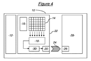
ブロックによるこのような符号化方法は、CMOSキャプチャなどの画像キャプチャのデジタル装置で使用することがあり、そのうちの光モジュールタイプの一例を図1に示す。 Such a block encoding method may be used in an image capture digital device such as a CMOS capture, and an example of the optical module type is shown in FIG.
この図では、たとえばCMOSキャプチャなどの撮像装置の光モジュール10は、光ブロック12と感光性素子であるマトリクス14とを有し、この感光性ダイオードは電動の読み取り手段(図示せず)と協働して撮像する画像の画素を形成する。
In this figure, an
画素マトリクス14は、シーケンス装置16およびアナログデジタル変換装置18と協働し、画素マトリクスでのデジタル画像を取得することができる。画素マトリクス14、シーケンス装置16およびアナログデジタル変換装置18は、取得したデジタル画像を伝送するインターフェース20とともに、一般に「イメージャ回路」またはCMOSキャプチャの「焦平面」と呼ぶ電子回路22を形成する。
The
イメージャ回路22のインターフェース20はこのほか、一般に物理的な電子的リンク24によってグラフィックスコプロセッサ回路28からデジタル画像を受信するインターフェース26に連結しており、この回路によって取得したデジタル画像の質を向上させるアルゴリズムをインプリメンテーションすることができ、前述したようなブロックごとの符号化方法を実践することができる場合もある。
In addition, the
CMOSキャプチャを備えるデジタルカメラやデジタルビデオカメラ、または携帯電話の光モジュールなどの一般大衆向けの画像取得装置には、多くの制約が課せられている。 Many limitations are imposed on general-purpose image acquisition devices such as digital cameras and digital video cameras with CMOS capture, or optical modules of mobile phones.
特に、イメージャ回路22とグラフィックスコプロセッサ回路28との間にある物理的な電子的リンク24の伝送レートには限界がある。例を挙げると、多くのイメージャ回路で遵守されているSMIA規格のプロトコルは、伝送レートを400Mbits/秒に制限している。しかし、毎秒30画像で2メガピクセルの各画素を10ビットに符号化したイメージャ回路を圧縮していないビデオでは、600Mbits/秒の伝送レートが必要となる。この伝送レートの制限が、ビデオモードでの解像度が一般に制限されている理由の一つである。
In particular, the transmission rate of the physical
さらに、電気消費量の削減が、画像キャプチャ装置などのモバイル機器に対する最大の制約となっている。このような画像キャプチャ装置の最大の電力消費源となっているのは、物理的な電子的リンク24によってイメージャ回路22とグラフィックスコプロセッサ回路28との間で行うデジタルデータの伝送であり、この消費量を削減する最良の方法が伝送するデータの量を減少させることであることは自明である。
Furthermore, the reduction of electricity consumption is the biggest restriction for mobile devices such as image capture devices. The largest power consumption of such an image capture device is the transmission of digital data between the
最後に、グラフィックスコプロセッサ回路28に搭載することができる最新世代の画質向上フィルタは、連続する複数の画像を蓄積する必要がある。メモリのコストにかかる経済的理由および画像の総情報量が増加するという理由により、このようなアルゴリズムは安価な装置に組み入れることは不可能である。
Finally, the latest generation image quality improvement filter that can be mounted on the
上記の3つの制約から、取得したデジタルデータを確実に圧縮し、複雑なフィルタリングのアルゴリズムを使用できるようにグラフィックスコプロセッサ回路28に導入するか、好ましくは物理的な電子的リンク24によって伝送量を制限できるようにイメージャ回路に導入する可能性が見込めるような画像の符号化方法が必要であることがわかる。
Because of the above three constraints, the acquired digital data can be reliably compressed and introduced into the
このほか、イメージャ回路のメガピクセル数で量子化した画像キャプチャ装置の空間解像度を向上させることが、現在一般大衆に対する最大の革新基準となっている点を考慮する必要がある。集積回路のコストおよび光モジュールを小型化する試行の理由から、イメージング回路の寸法を縮小する必要があることは明らかである。その結果、イメージャ回路またはグラフィックスコプロセッサ回路に符号化アルゴリズムを導入することは、常に複雑性の点で非常に厳しい制約がある。 In addition, it is necessary to consider that improving the spatial resolution of an image capture device quantized with the number of megapixels of an imager circuit is currently the largest innovation standard for the general public. Obviously, the size of the imaging circuit needs to be reduced due to the cost of the integrated circuit and the reasons for trying to miniaturize the optical module. As a result, the introduction of an encoding algorithm into an imager circuit or a graphics coprocessor circuit is always very strict in terms of complexity.
2005年5月、IEEE International Symposium on Circuits And Systems(回路およびシステムに関するIEEE国際シンポジウム)の第5巻、第5322〜5325ページに公表されたZhiqiang Linらによる文献「A CMOS image sensor for focal plane decomposition(焦平面分割のためのCMOSイメージセンサー」には、従来のウェーブレットへの変換による符号化プロセスを記憶する必要がないCMOSキャプチャのイメージャ回路周辺で取得する画素値の並列処理を想定したブロックごとの符号化方法が記載されている。 In May 2005, the article “A CMOS image sensor sensor sf ense sensor sf ense samp sf es s mes s s nc f s e n s mes s mes s nor f s e s” ”from the 5 th pp. 5322 to 5325 of the IEEE International Symposium on Circuits And Systems (IEEE International Symposium on Circuits and Systems), 5322-5325. “CMOS image sensor for focal plane division” is a block-by-block code that assumes parallel processing of pixel values acquired around the imager circuit of a CMOS capture that does not need to store an encoding process by conversion to a conventional wavelet. Is described.
その代わりに、この並列処理を実行するには、画素が大きく複雑なものとなってしまい、これでは一般大衆用に製品を小型化するという要求と両立させることが困難になる。 Instead, to perform this parallel processing, the pixels are large and complex, which makes it difficult to meet the demands of miniaturizing products for the general public.
2007年1月、IEEE Transactions on Circuits and Systems I(回路およびシステムに関するIEEEトランザクションI)の第54巻、第1号、第26〜34ページに公表されたAshkan Olyaeiらによる文献「Focal−plane spatially oversampling CMOS image compression sensor(焦平面への空間的オーバーサンプリングによるCMOS画像圧縮センサ」にも、イメージャ回路で実行するブロックごとの符号化方法が記載されている。ここで検討されている2次元カーネルは、2×2画素から8×8画素の範囲であり、この方法では分割前に1ブロックの全画素値を記憶する必要がある。 January 2007, IEEE Transactions on Circuits and Systems I, IEEE Transaction I on Circuits and Systems, Vol. 54, No. 1, pages 26-34, the document “Focal-plane spatials” published by Ashkan Olya et al. A CMOS image compression sensor (CMOS image compression sensor by spatial oversampling to the focal plane) also describes a block-by-block encoding method executed by an imager circuit. The range is from 2 × 2 pixels to 8 × 8 pixels. In this method, it is necessary to store all pixel values of one block before division.
さらに、上記の2つの文献に記載されているいずれの方法にも一般のCMOSキャプチャの特殊性が考慮されていない。一般のCMOSキャプチャでは、シーケンス装置16で画像の画素値を順に読み取るモードを使用するが、これは画像の最初の行から最後の行まで1行ずつ処理する電子シャッターモードである。連続的な電子シャッターによって行を読み取るこのモードは、特に低価格のCMOSキャプチャの感光性の欠点を補うことを目的としている。
Further, none of the methods described in the above two documents considers the special characteristics of general CMOS capture. In general CMOS capture, a mode in which pixel values of an image are sequentially read by the
しかし、サイズ、電気消費量、ビデオモードを確保する必要性という電子的な制約により、イメージング回路もこの読み取りモードで作動させなければならなくなる。このモードより、デジタル画像をやむなく1行ずつ読み取り、別々の2行の画素が一時的にコヒーレントでなくなるということが起こるが、これはこの画素が正確に1シーンの同じ瞬間を表してはいないためである。 However, due to electronic constraints such as size, electricity consumption, and the need to ensure video mode, the imaging circuit must also operate in this reading mode. This mode inevitably causes the digital image to be read line by line, and the two separate lines of pixels temporarily become incoherent, because these pixels do not accurately represent the same moment in a scene. It is.
この作動モードによって起こることは、前述した符号化の原理では、このモードを適用するデジタル画像の水平方向および垂直方向には共通のコヒーレンスがあることが前提となるが、異なる行同士では完全には相関関化されないということである。さらに、たとえば8×8画素サイズの画像ブロックごとの符号化を実行するには、処理を実施する前に必要な行全体を順に取得して蓄積する必要がある。一般にイメージャ回路でのメモリは限られていることから、この制約には問題が生じる。 What happens with this mode of operation is that the coding principle described above assumes that there is a common coherence in the horizontal and vertical directions of the digital image to which this mode is applied, but it is completely between different rows. It is not correlated. Further, for example, in order to execute encoding for each image block having an 8 × 8 pixel size, it is necessary to sequentially acquire and accumulate all necessary rows before performing the processing. In general, the memory in the imager circuit is limited, and this restriction causes a problem.
したがって、前述の問題および制約を解消できる符号化方法を想定することが望ましい。 Therefore, it is desirable to assume an encoding method that can eliminate the aforementioned problems and limitations.
よって本発明は、複数の独立したブロックで構成される画素のラスターイメージのブロックごとの符号化方法であって、n画素を垂直方向に分割する1次元カーネルとp画素を水平方向に分割する1次元カーネルとを組み合わせて適用することによって所定の離散関数基底でこの画像のブロックを連続的に2次元分割するステップを含み、ブロックの水平方向は、1行ずつ順に読み取るモードおよび/または伝送するモードでのラスターイメージの行の方向であると定義する符号化方法において、
− 各ブロックの水平方向の画素数を表す水平寸法Pは、pの倍数であるためP=k.pと定義し、解像度logp(P)での分割を水平方向に分割する1次元カーネルを用いて実行し、
− 各ブロックの垂直方向の画素数を表す垂直寸法Nは、nの倍数であるためN=l.nと定義し、解像度logn(N)での分割を垂直方向に分割する1次元カーネルを用いて実行し、
所与のnおよびpの値に対し、垂直寸法Nが水平寸法Pよりも小さくなるようにkおよびlの値を選択する符号化方法を目的とする。
Therefore, the present invention is an encoding method for each block of a raster image of pixels composed of a plurality of independent blocks, and includes a one-dimensional kernel that divides n pixels in the vertical direction and 1 that divides p pixels in the horizontal direction. A mode in which a block of this image is continuously divided into two dimensions in a predetermined discrete function basis by applying in combination with a dimensional kernel, and the horizontal direction of the block is a mode of reading and / or transmitting one by one in sequence In the encoding method that defines the direction of the rows of the raster image at
The horizontal dimension P representing the number of pixels in the horizontal direction of each block is a multiple of p, so P = k. p is defined, and the division at resolution log p (P) is performed using a one-dimensional kernel that divides in the horizontal direction,
The vertical dimension N representing the number of pixels in the vertical direction of each block is a multiple of n, so N = 1. n, and perform the division at resolution log n (N) using a one-dimensional kernel that divides in the vertical direction,
It is an encoding method that selects the values of k and l such that the vertical dimension N is smaller than the horizontal dimension P for a given value of n and p.
ブロックの行数を列数よりも少なくすると、画素値を1行ずつ順に取得する段階では、同一列の画素のコヒーレンスよりも大きい同一行の画素のコヒーレンスが正確に考慮される。よってこの方法は、有利なように広く一般大衆に使用できる安価な画像キャプチャ装置で使用される。さらに、ブロックの行数を列数よりもさらに少なくすると、この方法を用いる装置のメモリはさらに少なくて済むため、この方法をイメージャ回路に導入する案はさらに容易になる。 When the number of rows in the block is less than the number of columns, the coherence of pixels in the same row that is larger than the coherence of pixels in the same column is accurately taken into consideration in the step of sequentially obtaining pixel values row by row. Thus, this method is advantageously used with inexpensive image capture devices that can be used widely and to the general public. Furthermore, if the number of rows in the block is further reduced than the number of columns, the device using this method requires less memory, so that it is easier to introduce this method into the imager circuit.
選択的に、水平方向および垂直方向に分割する1次元カーネルn=p=2が、ウェーブレットに分解するハール離散関数であってもよい。この場合、加算器および減算器を用いることによって、本発明による符号化方法のきわめて簡易なインプリメンテーションが可能となる。 Alternatively, the one-dimensional kernel n = p = 2 that divides in the horizontal direction and the vertical direction may be a Haar discrete function that decomposes into wavelets. In this case, by using an adder and a subtracter, a very simple implementation of the encoding method according to the invention is possible.
同じく選択的に、ラスターイメージブロックの2次元分割が、解像度1での垂直方向の分割と、解像度log2(k)+1での水平方向の分割との組み合わせを含み、垂直寸法がN=2画素で水平寸法がP=2.k画素のブロックに実行するようにしてもよい。この場合、この方法を用いる装置のメモリは少なくて済む。
Also optionally, the two-dimensional division of the raster image block includes a combination of vertical division at
同じく選択的に、各ブロックは、一辺が4画素の正方形となる互いに連続するk個のサブブロックで構成され、ラスターイメージブロックのいずれか1つの2次元分割が、垂直方法と水平方向に分割する1次元カーネルを組み合わせるハールの2次元カーネルを用いてk個のサブブロックをそれぞれ変換したのち、水平方向に分割する1次元カーネルを用いて解像度log2(k)で水平方向に分割し、この分割をk個のサブブロックを変換して得られた強力なエントロピーを有するk個の要素に適用するようにしてもよい。 Similarly, each block is composed of k consecutive sub-blocks each having a square of 4 pixels, and any one two-dimensional division of the raster image block is divided in the vertical direction and in the horizontal direction. Each of the k sub-blocks is converted using a Haar 2D kernel that combines the 1D kernels, and then divided horizontally using a 1D kernel that is divided in the horizontal direction with resolution log 2 (k). May be applied to k elements having strong entropy obtained by transforming k sub-blocks.
同じく選択的に、本発明による符号化方法がさらに
− 画像ブロックを連続的に2次元分割するステップに続いて、符号変換する語で構成される第1の2進データ列を供給するステップと、
− 所定の可変長符号のエントロピー符号を用いて、第1の2進データ列を圧縮した第2の2進データ列にエントロピー的に符号変換し、第1の2進データ列の各符号語を変換後の符号語に変換するステップ
とを含み、
第1の2進データ列の符号語のノイズレベルを表すものと考える重みの小さいビット数をBと表記する所定数をベースとして、第1の2進データ列の各符号語に、
− 符号語を第1および第2のサブ符号語に細分化して、第1のサブ符号語が符号語の重みの小さいBビットを有し、第2のサブ符号語が符号語の重みの大きい別のビットを有するようにするステップと、
− 所定のエントロピー符号を第2のサブ符号語に適用して変換後の第2のサブ符号語を得るステップと、
− 変換した第1のサブ符号語と第2のサブ符号語を連結させることによって前記変換後の符号語を得るステップとを適用する段階を含むことができるようにしてもよい。
Also optionally, the encoding method according to the present invention further comprises: supplying a first binary data string composed of words to be transcoded, following the step of continuously dividing the image block into two dimensions;
-Entropically code-converts the first binary data string into a compressed second binary data string using an entropy code of a predetermined variable length code, and converts each codeword of the first binary data string Converting to a converted codeword,
Based on a predetermined number represented by B as a bit number with a small weight that is considered to represent the noise level of the code word of the first binary data string, each code word of the first binary data string is
-Subdividing the codeword into first and second subcodewords, the first subcodeword has B bits with low codeword weight, and the second subcodeword has high codeword weight Having another bit; and
Applying a predetermined entropy code to the second subcodeword to obtain a transformed second subcodeword;
-It may be possible to include a step of applying the step of obtaining the converted codeword by concatenating the converted first subcodeword and the second subcodeword.
同じく選択的に、本発明による符号化方法がさらに、最初の行から最終行まで1行ずつ画像の画素値を順に読み取り、N行とP列からなる少なくとも1つのブロックを有する連続するN行を読み取る間に、この少なくとも1つのブロックの2次元分割を実行するステップを含むようにしてもよい。 Also optionally, the encoding method according to the present invention further reads the pixel values of the image one row at a time from the first row to the last row, and obtains consecutive N rows having at least one block of N rows and P columns. While reading, a step of performing a two-dimensional division of the at least one block may be included.
同じく選択的に、本発明による符号化方法がさらに、連続するN行を読み取る間に、
− 連続する最初のN−1行を読み取り、記憶するステップと、
− N番目の行のデータを取得する間に、この行の少なくとも1つのブロックの2次元分割を実行するステップ
とを含むようにしてもよい。
Also optionally, while the encoding method according to the invention further reads N consecutive rows,
-Reading and storing the first consecutive N-1 rows;
-Performing a two-dimensional division of at least one block of this row while acquiring data of the Nth row.
また、本発明は、最初の行から最後の行まで1行ずつ画像の画素値を順に読み取る手段と、上に定義したような符号化方法のステップを実行するように想定した符号化手段とを有する画像キャプチャ装置も目的とする。 The present invention further comprises means for sequentially reading pixel values of the image line by line from the first line to the last line, and an encoding means that is assumed to execute the steps of the encoding method as defined above. Another object is an image capture device.
選択的に、本発明による画像キャプチャ装置が、画像を取り込み、取り込んだこの画像をアナログデジタル変換するためのイメージャ回路と、このイメージャ回路とは別に、取り込んだ画像をデジタル処理するためにこのイメージ回路に電子的に連結しているコプロセッサ回路とを有することができ、符号化手段がイメージャ回路に搭載されるようにしてもよい。 Optionally, an image capture device according to the present invention captures an image and converts the captured image to analog-to-digital, and separately from the imager circuit, the image capture circuit digitally processes the captured image. A coprocessor circuit electronically coupled to the imager circuit, and the encoding means may be mounted on the imager circuit.
この画像キャプチャ装置は、たとえばデジタルカメラやデジタルビデオカメラ、あるいは遠距離通信またはこのようなカメラや内蔵ビデオを備えるあらゆるデータ処理を行う携帯可能な装置である。 The image capture device is, for example, a digital camera or digital video camera, or a portable device that performs any data processing with telecommunications or such camera and built-in video.
最後に、本発明は、通信ネットワークからダウンロード可能なコンピュータプログラムおよび/またはコンピュータでの読み取りが可能な媒体に保存されたコンピュータプログラムおよび/またはプログラムコードのインストラクションを含むプロセッサでの実行が可能なコンピュータプログラムで、このプログラムをコンピュータ上で実行する際に、前述した符号化方法のステップを実行するコンピュータプログラムも目的とする。 Finally, the present invention relates to a computer program that can be downloaded from a communication network and / or a computer program stored on a computer-readable medium and / or a computer program that can be executed on a processor including instructions for the program code. Thus, a computer program for executing the above-described encoding method steps when the program is executed on a computer is also an object.
本発明は、添付の図を参照しながら例としてのみ挙げた以下の説明文を読めばさらによく理解できるであろう。以下、図面を説明する。 The invention will be better understood by reading the following description, given by way of example only with reference to the accompanying drawings, in which: The drawings are described below.
まず、本発明の第1の局面では、画素のラスターイメージの新たな情報源符号化方法を提案する。次に、本発明の第2の局面では、エントロピー符号化を提案する。エントロピー符号化は、情報源符号化によって得られるパラメータ値を有する符号語で構成される2進データ列に適用するのが有利である。 First, in the first aspect of the present invention, a new information source encoding method for pixel raster images is proposed. Next, in the second aspect of the present invention, entropy coding is proposed. Entropy coding is advantageously applied to binary data sequences composed of codewords having parameter values obtained by source coding.
第1の局面 : 所定の離散関数基底で分割する情報源符号化 First aspect: Information source coding divided by a predetermined discrete function basis
次に詳細に説明する符号化方法は、この画像の画素値を1行ずつ順に読み取るモード(たとえば、画像の最初の行から最後の行まで1行ずつ読み取る電子シャッターモード)を適用するキャプチャ装置で得られた画像に関する。画素マトリクスを完全に封鎖するメカニカルシャッターモードであっても、画素値の読み取りを1行ずつ順に行う瞬間からこの方法は別に適応される。 The encoding method described in detail below is a capture device that applies a mode in which the pixel values of this image are read sequentially line by line (for example, an electronic shutter mode that reads line by line from the first line to the last line of the image). It relates to the obtained image. Even in the mechanical shutter mode in which the pixel matrix is completely blocked, this method is applied separately from the moment when reading of pixel values is sequentially performed row by row.
1行ずつ順に読み取るモードに符号を適応させるため、垂直寸法が水平寸法よりも小さい独立した矩形ブロックに画像を細分化する。ここでは、画像およびこの画像を構成するブロックの水平方向は、1行ずつ順に読み取るモードを選択した際の画像の行の方向であると定義する。よって、画像およびこの画像を構成するブロックの垂直方向は、画像の列の方向であると定義する。
In order to adapt the code to the mode of reading one line at a time, the image is subdivided into independent rectangular blocks whose vertical dimension is smaller than the horizontal dimension. Here, the horizontal direction of the image and the blocks constituting the image is defined as the direction of the row of the image when the mode for sequentially reading one row at a time is selected. Therefore, the vertical direction of the image and the blocks constituting the image is defined as the direction of the image column.
さらに正確には、図2に非限定的に示した例では、各ブロックの横の画素数を表す水平寸法Pは16に設定され、各ブロックの縦の画素数を表す垂直寸法Nは2に設定されている。よって各ブロックは、連続する2行にわたる32画素を有する。 More precisely, in the non-limiting example shown in FIG. 2, the horizontal dimension P representing the number of horizontal pixels in each block is set to 16, and the vertical dimension N representing the number of vertical pixels in each block is set to 2. Is set. Thus, each block has 32 pixels over two consecutive rows.
このようなブロックの2次元分割は、ハールの離散ウェーブレット基底で実行する。この基底では、垂直射影および水平射影の1次元カーネルはそれぞれn=p=2画素となることはよく知られている。このような分割の導入は単純に加算器および減算器を用いて行うことができるため、ハールのウェーブレット基底が選択される。これについてはこのあと図3を参照して明らかにする。 Such two-dimensional partitioning of blocks is performed on Haar's discrete wavelet basis. It is well known that on this basis, the one-dimensional kernels for vertical projection and horizontal projection each have n = p = 2 pixels. Since the introduction of such a division can be performed simply using an adder and a subtracter, the Haar wavelet base is selected. This will be clarified later with reference to FIG.
したがって、この例によれば、ブロックの2画素の各列に次数log2(2)=1の射影を垂直方向に実行する。この射影次数1は、2画素を加算して低周波または強エントロピーの第1のパラメータを得て、そこから2画素を減算して高周波または弱エントロピーの第2のパラメータを得るというものである。
Therefore, according to this example, projection of the order log 2 (2) = 1 is executed in the vertical direction on each column of two pixels of the block. The
引き続きこの例によれば、ブロックの16画素の各行に次数log2(16)=4の射影を水平方向に実行する。この射影次数4は、
− 対象となる行の16画素を2つずつ加算して次数1の低周波または強エントロピーの第1のパラメータを8個得て、それを2つずつ減算して次数1の高周波または弱エントロピーの第2のパラメータを8個得ることと、
− 次数1の低周波(または強エントロピー)のパラメータ8個を2つずつ加算して次数2の低周波または強エントロピーの第1のパラメータを4個得て、それを2つずつ減算して次数2の高周波または弱エントロピーの第2のパラメータを4個得ることと、
−次数2の低周波(または強エントロピー)のパラメータ4個を2つずつ加算して次数3の低周波または強エントロピーの第1のパラメータを2個得て、それを2つずつ減算して次数3の高周波または弱エントロピーの第2のパラメータを2個得ることと、
−次数3の低周波(または強エントロピー)のパラメータ2個を加算して次数4の低周波または強エントロピーの第1のパラメータを1個得て、それを減算して次数4の高周波または弱エントロピーの第2のパラメータを1個得ることからなる。
Continuing with this example, a projection of order log 2 (16) = 4 is performed in the horizontal direction on each row of 16 pixels of the block. This
-Add 16 pixels of the target row two by two to obtain the first parameter of
-
-Add four low frequency (or strong entropy) parameters of
-
同様に、この例によれば、垂直射影、および水平射影の第1の次数は、ハールの2次元カーネルを用いて2次元射影の形態で同時に実行することができ、2×16画素の各ブロックが、2×2画素の正方形となる互いに連続する8個のサブブロックで構成されると考える。このような射影では低周波または強エントロピーのパラメータが1つ、およびサブブロックによって高周波または弱エントロピーのパラメータが3つ生成される。 Similarly, according to this example, the first order of vertical projection and horizontal projection can be performed simultaneously in the form of a two-dimensional projection using Haar's two-dimensional kernel, and each block of 2 × 16 pixels Are composed of eight consecutive sub-blocks that are 2 × 2 pixel squares. In such a projection, one low frequency or strong entropy parameter and three high frequency or weak entropy parameters are generated by the sub-block.
次に、得られた低周波(または強エントロピー)のパラメータ8個に次数3の水平射影を適用する。 Next, a degree 3 horizontal projection is applied to the eight low frequency (or strong entropy) parameters obtained.
さらに正確には、第1の読み取りステップ100の段階では、イメージャ回路22は、たとえば1行ずつ取り込む電子シャッターモードで第1の行Aから順に読み取る。すると、この行の画素値が記憶される。第1の行Aの画素数は、有利なように16または16の倍数、つまりブロックの水平寸法の倍数とする。
More precisely, in the stage of the
次にイメージャ回路22は、たとえば1行ずつ取り込む電子シャッターモードで第2の行Bを順に読み取る。
Next, the
この第2の行Bを読み取る間、読み取ったAおよびBの2行を1組とする各ブロックに2次元の射影を実行するステップ102に移る。図2に示す例では、簡略化することのみを目的として、各行が16画素を有すると考える。つまりこれは、この例では特に簡略化しているが、AおよびBの2行の組が単一のブロックを有するということである。行Aの画素はa0、...、a15、行Bの画素はb0、...、b15と表記する。 While the second row B is being read, the process proceeds to step 102 where a two-dimensional projection is performed on each block in which the read two rows A and B are set as one set. In the example shown in FIG. 2, for the sake of simplicity only, each row is considered to have 16 pixels. In other words, this is particularly simplified in this example, but the two-row set of A and B has a single block. The pixels in row A are a 0 ,. . . , A 15 , row B pixels are b 0 ,. . . , It referred to as b 15.
このa0、...、a15およびb0、...、b1532画素は、Bi(0≦i≦7)と表記する正方形のサブブロック8個で構成されると考える。この正方形のサブブロックBiはそれぞれ4個の画素a2i、a2i+1、b2iおよびb2i+1を有する。 This a 0,. . . , A 15 and b 0 ,. . . , B 15 32 pixels are considered to be composed of eight square sub-blocks denoted as B i (0 ≦ i ≦ 7). Each square sub-block B i has four pixels a 2i , a 2i + 1 , b 2i and b 2i + 1 .
ステップ102では、4つのハールブロック(それぞれLL1、HL1、LH1およびHH1と表記)で構成される基底で正方形のサブブロックBiをそれぞれ射影する。この4ブロックは、図2では斜線(減算した値)または白(加算した値)の4画素の正方形のブロックで示しており、わかりやすいようにステップ102の図の左部に配置し、その反対側には生成される係数を示している。
In
第1のハールブロックLL1は、低周波要素であることを示す。画像は基本的に局地の外縁によって1つ1つ分離されている同質の領域で構成されているため、画像の一般特性を考慮すると、この低周波要素も強エントロピーのパラメータである。その射影係数は、次の計算によって得られる。
LL1(Bi)=a2i+a2i+1+b2i+b2i+1
The first Haar block LL1 indicates a low frequency element. Since the image is basically composed of homogeneous regions separated one by one by the outer edge of the local area, considering the general characteristics of the image, this low frequency element is also a strong entropy parameter. The projection coefficient is obtained by the following calculation.
LL1 (B i ) = a 2i + a 2i + 1 + b 2i + b 2i + 1
第2のハールブロックHL1は高周波要素であることを示し、さらに正確には、垂直方向に高周波かつ水平方向に低周波の要素である。画像は基本的に局地の外縁によって1つ1つ分離されている同質の領域で構成されているため、画像の一般特性を考慮すると、この高周波要素も弱エントロピーのパラメータである。その射影係数は、次の計算によって得られる。
HL1(Bi)=a2i+a2i+1−b2i−b2i+1
The second Haar block HL1 indicates a high-frequency element, and more precisely, a high-frequency element in the vertical direction and a low-frequency element in the horizontal direction. Since the image is basically composed of homogeneous regions separated one by one by the outer edge of the local area, considering the general characteristics of the image, this high-frequency element is also a weak entropy parameter. The projection coefficient is obtained by the following calculation.
HL1 (B i ) = a 2i + a 2i + 1 −b 2i −b 2i + 1
第3のハールブロックLH1は高周波で弱エントロピーの要素であることを示し、さらに正確には、水平方向に高周波かつ垂直方向に低周波の要素である。その射影係数は、次の計算によって得られる。
LH1(Bi)=a2i−a2i+1+b2i−b2i+1
The third Haar block LH1 indicates a high frequency, weak entropy element, and more precisely, a high frequency element in the horizontal direction and a low frequency element in the vertical direction. The projection coefficient is obtained by the following calculation.
LH1 (B i ) = a 2i −a 2i + 1 + b 2i −b 2i + 1
第4のハールブロックHH1高周波で弱エントロピーの要素であることを示し、さらに正確には、水平方向に高周波かつ垂直方向に高周波の要素である。その射影係数は、次の計算によって得られる。
HH1(Bi)=a2i−a2i+1−b2i+b2i+1
The fourth Haar block HH1 indicates a weak entropy element at a high frequency, and more precisely, a high frequency element in the horizontal direction and a high frequency element in the vertical direction. The projection coefficient is obtained by the following calculation.
HH1 (B i ) = a 2i −a 2i + 1 −b 2i + b 2i + 1
前述のハールブロックの基底で正方形のサブブロックBiすべてを射影すると、係数は4×8=32となる。高周波で弱エントロピーである24個の係数は保存され(8係数HL1(Bi)、8係数LH1(Bi)、8係数HH1(Bi))、低周波で強エントロピーである8係数LL1(Bi)は保存されずに次数3の水平射影を実行するステップ104で処理される。図2のステップ102の図では、保存される係数はグレーで示し、保存されない係数は白で示している。
When all the square sub-blocks B i are projected at the base of the Haar block, the coefficient is 4 × 8 = 32. The 24 coefficients that are weak entropy at high frequency are stored (8 coefficients HL1 (B i ), 8 coefficients LH1 (B i ), 8 coefficients HH1 (B i )), and 8 coefficients LL1 (8 coefficients LL1 (B i )) that are strong entropy at low frequencies. B i ) is not stored but is processed in
ステップ104では、第1の次数で、L2およびH2で示す2つの1次元ハールブロックで構成される基底で係数{LL1(B2i);LL1(B2i+1)}の各ペアを射影する。図2にはブロックH2のみを、水平方向に配置される2つの「画素」の矩形ブロックで示し、一方を白(加算した値)、もう一方を斜線(減算した値)で示している。このブロックH2は、わかりやすいようにステップ104の左部に配置し、その反対側には生成されて保存される係数を示している。ブロックL2によって生成される係数は、保存されずに水平射影の第2の次数で処理される。これはステップ104を簡略化するために図示しておらず、ブロックL2も同様である。
In
第1の1次元ハールブロックL2は、低周波で強エントロピーの要素であることを示す。その射影係数は、次の計算によって得られる。
L2(i)=LL1(B2i)+LL1(B2i+1)
The first one-dimensional Haar block L2 indicates that it is a strong entropy element at a low frequency. The projection coefficient is obtained by the following calculation.
L2 (i) = LL1 (B 2i ) + LL1 (B 2i + 1 )
第2の1次元ハールブロックH2は、高周波で弱エントロピーの要素であることを示す。その射影係数は、次の計算によって得られる。
H2(i)=LL1(B2i)−LL1(B2i+1)
The second one-dimensional Haar block H2 indicates that it is a high-frequency weak entropy element. The projection coefficient is obtained by the following calculation.
H2 (i) = LL1 (B 2i) -LL1 (B 2i + 1)
前述した1次元ハールブロックの基底で係数{LL1(B2i);LL1(B2i+1)}の4ペアを射影すると8つの係数が得られる。高周波で弱エントロピーの4係数は保存され(4係数H2(i))、低周波で強エントロピーの4係数L2(i)は水平射影の第2の次数で処理される。図2にある図では、保存される係数をグレーで示し、保存されない係数は示していない。 When four pairs of coefficients {LL1 (B 2i ); LL1 (B 2i + 1 )} are projected on the basis of the above-described one-dimensional Haar block, eight coefficients are obtained. Four coefficients of high entropy and weak entropy are stored (4 coefficients H2 (i)), and four coefficients L2 (i) of low entropy and strong entropy are processed in the second order of the horizontal projection. In the diagram in FIG. 2, the saved coefficients are shown in gray and the unsaved coefficients are not shown.
水平射影の第2の次数では、L3およびH3で表記されてL2およびH2と同じであるが2倍の規模で作動する2つの1次元ハールブロックで構成される基底で係数{L2(2i);L2(2i+1)}の各ペアを射影する。図2ではブロックH3のみを、水平方向に配置される2つの「画素」の矩形ブロックで示し、一方を白(加算した値)、もう一方を斜線(減算した値)で示している。このブロックH3は、わかりやすいようにステップ104の左部に配置し、その反対側には生成されて保存される係数を示している。ブロックL3によって生成される係数は、保存されずに水平射影の第3の次数で処理される。これはステップ104を簡略化するために図示しておらず、ブロックL3も同様である。
In the second order of the horizontal projection, the coefficients {L2 (2i) on the basis composed of two one-dimensional Haar blocks, denoted L3 and H3, which are the same as L2 and H2 but operate at twice the scale; Project each pair of L2 (2i + 1)}. In FIG. 2, only the block H3 is shown as a rectangular block of two “pixels” arranged in the horizontal direction, one is shown as white (added value) and the other is shown as a diagonal line (subtracted value). This block H3 is arranged on the left side of
第1の1次元ハールブロックL3は、低周波で強エントロピーの要素であることを示す。その射影係数は、次の計算によって得られる。
L3(i)=L2(2i)+L2(2i+1)
The first one-dimensional Haar block L3 indicates that it is a strong entropy element at a low frequency. The projection coefficient is obtained by the following calculation.
L3 (i) = L2 (2i) + L2 (2i + 1)
第2の1次元ハールブロックH3は、高周波で弱エントロピーの要素であることを示す。その射影係数は、次の計算によって得られる。
H3(i)=L2(2i)−L2(2i+1)
The second one-dimensional Haar block H3 indicates a high-frequency weak entropy element. The projection coefficient is obtained by the following calculation.
H3 (i) = L2 (2i) -L2 (2i + 1)
前述した1次元ハールブロックの基底で係数{L2(2i);L2(2i+1)}の2ペアを射影すると、4つの係数が得られる。高周波で弱エントロピーの2係数は保存され(係数H3(i)2個)、低周波で強エントロピーの2係数L3(i)は水平射影の第3の次数で処理される。図2にある図では、保存される係数をグレーで示し、保存されない係数は示していない。 When two pairs of coefficients {L2 (2i); L2 (2i + 1)} are projected on the basis of the above-described one-dimensional Haar block, four coefficients are obtained. Two coefficients with high frequency and weak entropy are stored (two coefficients H3 (i)), and two coefficients L3 (i) with low frequency and strong entropy are processed in the third order of the horizontal projection. In the diagram in FIG. 2, the saved coefficients are shown in gray and the unsaved coefficients are not shown.
水平射影の第3の次数では、L4およびH4で表記されてL3およびH3と同じであるが2倍の規模で作動する2つの1次元ハールブロックで構成される基底で2つの係数L3(0)およびL3(1)を射影する。図2ではブロックH4を、水平方向に配置される2つの「画素」からなる矩形ブロックで示し、一方を白(加算した値)、もう一方を斜線(減算した値)で示している。このブロックH4は、わかりやすいようにステップ104の図の左部に配置し、その反対側には生成されて保存される係数を示している。図2ではブロックL4を、水平方向に配置される2つの白い「画素」からなる矩形ブロックで示している(加算した値)。このブロックL4は、わかりやすいようにステップ104の図の左部に配置し、その反対側には生成されて保存される係数を示している。
In the third order of the horizontal projection, two coefficients L3 (0) in a base composed of two one-dimensional Haar blocks, denoted L4 and H4, which are the same as L3 and H3 but operate at twice the scale And L3 (1). In FIG. 2, the block H <b> 4 is shown as a rectangular block made up of two “pixels” arranged in the horizontal direction, one being white (added value) and the other being hatched (subtracted value). This block H4 is arranged on the left side of the figure of
第1の1次元ハールブロックL4は、低周波で強エントロピーの要素であることを示す。その射影係数は、次の計算によって得られる。
L4(0)=L3(0)+L3(1)
The first one-dimensional Haar block L4 indicates that it is a strong entropy element at a low frequency. The projection coefficient is obtained by the following calculation.
L4 (0) = L3 (0) + L3 (1)
第2の1次元ハールブロックH4は、高周波で弱エントロピーの要素であることを示す。その射影係数は、次の計算によって得られる。
H4(0)=L3(0)−L3(1)
The second one-dimensional Haar block H4 indicates a high-frequency weak entropy element. The projection coefficient is obtained by the following calculation.
H4 (0) = L3 (0) -L3 (1)
前述した1次元ハールブロックの基底で2つの係数L3(0)およびL3(1)を射影すると、2つの係数H4(0)およびL4(0)となる。この2つの係数は保存され、図2ではグレーで示している。 When the two coefficients L3 (0) and L3 (1) are projected on the basis of the one-dimensional Haar block, the two coefficients H4 (0) and L4 (0) are obtained. These two coefficients are stored and are shown in gray in FIG.
結論として、8係数HH1(Bi)、8係数LH1(Bi)、8係数HL1(Bi)、4係数H2(i)、2係数H3(i)、1係数H4(0)および1係数L4(0)、すなわち32係数を保存する。このように、損失のない符号を形成する可逆変換を実行し、強エントロピーで単一の係数を供給し、係数L4(0)は該当するブロックの画素の平均を表す。 In conclusion, 8 coefficients HH1 (B i ), 8 coefficients LH1 (B i ), 8 coefficients HL1 (B i ), 4 coefficients H2 (i), 2 coefficients H3 (i), 1 coefficient H4 (0) and 1 coefficient Save L4 (0), ie 32 coefficients. In this way, a reversible transformation that forms a lossless code is performed, a single coefficient is supplied with strong entropy, and the coefficient L4 (0) represents the average of the pixels of the corresponding block.
図3は、前述した方法を実践するのに考えられるアーキテクチャの一例を示す。 FIG. 3 shows an example of a possible architecture for practicing the method described above.
提案したアーキテクチャの第1のステップ40は、「+」のシンボルで示す加算器、「−」のシンボルで示す減算器、および記憶素子を有し、この各記憶素子は1つの係数のサイズを記憶し、「z−1」のシンボルで示している。この第1のステップ40は、前述したようなステップ102、104を実行し、行Bの画素を読み終わるたびに係数HH1(Bi)、LH1(Bi)、HL1(Bi)、H2(i)、H3(i)、H4(0)およびL4(0)(図3およびこれ以降の説明では簡略化のためHH1、LH1、HL1、H2、H3、H4およびL4と表記)を提供する。
The
従来のように、記憶素子「z−1」を使用する加算器および減算器、すなわち次数3の水平射影を実行し、いわば8つのパラメータに対してハールの水平変換を行う加算器および減算器で供給されるデータも、2次元分割した結果の係数が最終的にもとの画素と同じ係数となるように変換の各次数でサブサンプリングされることがわかる。 Conventionally, an adder and a subtractor that use a storage element “z −1 ”, that is, an adder and a subtractor that perform a horizontal projection of degree 3 and perform a Haar horizontal conversion on eight parameters. It can be seen that the supplied data is also subsampled at each order of conversion so that the coefficient resulting from the two-dimensional division finally becomes the same coefficient as the original pixel.
次に、各ブロックのこの2次元分割で得られた係数HH1、LH1、HL1、H2、H3、H4およびL4は、損失を伴う符号化を実行する量子化ブロック42で量子化される場合もある。
Next, the coefficients HH1, LH1, HL1, H2, H3, H4, and L4 obtained by this two-dimensional division of each block may be quantized by a
この量子化ブロック42を出たとき、つまり情報源符号化のステップ40の直後に、係数は、最初の画像を表す2進データ列のサイズの最適化を実行するエントロピー符号化ブロック44を用いて符号変換される。
When leaving this
さらに一般的には、前述の方法は、通信ネットワークからダウンロード可能なコンピュータプログラムおよび/またはコンピュータでの読み取りが可能な媒体に保存されたコンピュータプログラムおよび/またはプログラムコードのインストラクションを含むプロセッサでの実行が可能で、図2を参照しながら説明したステップを実行するコンピュータプログラムによって実践することができる。 More generally, the method described above can be performed on a processor that includes instructions for a computer program and / or program code stored in a computer program and / or computer readable medium that can be downloaded from a communication network. It can be implemented by a computer program that performs the steps described with reference to FIG.
この方法は、画像キャプチャ装置のさまざまな箇所に導入することができるが、特に、画像の蓄積を可能にする圧縮素子としてグラフィックスコプロセッサ回路28に導入したり、イメージャ回路22に導入したりすることができる。これは図4に示すように、情報源符号化器30の形態でイメージャ回路22に導入するのが有利である。実際に、この場合は、物理的な電子的リンク24で許容できる伝送レートは大幅に減少する。
This method can be introduced in various places of the image capture device, and in particular, it is introduced into the
図4では、情報源符号化器30は、アナログデジタル変換装置18を出たあとで、伝送用インターフェース20の直前にある。インプリメンテーションのさまざまな変形例によれば、アナログ分野でのインプリメンテーションも可能で、アナログデジタル変換装置18の上流に設置したり、変換装置18の前または後で、画素マトリクス14の列の下にある1つまたは複数の並列素子の状態で考案したりすることもできる。
In FIG. 4, the
図4に部分的に示している画像キャプチャ装置は、たとえばデジタルカメラやデジタルビデオカメラ、あるいは遠距離通信またはこのようなカメラや内蔵ビデオを備えるあらゆるデータ処理を行う携帯可能な装置であることがわかる。 It can be seen that the image capture device shown in part in FIG. 4 is a portable device, for example a digital camera or digital video camera, or a telecommunications or any data processing device with such a camera or built-in video. .
前述したような符号化方法によって、1行ずつ順に読み取るモードを備える画像キャプチャ装置から利便性を引き出せることは明らかである。この方法は、このような装置のイメージャ回路22に容易に導入することができる。各ブロックが2行と多数の列を有し、このようなブロックごとに処理を行うには1行のみしか記憶する必要がないため、このイメージャ回路22の蓄積スペースが限られているとしても導入することができる。
It is obvious that the above-described encoding method can bring out convenience from an image capture device having a mode for sequentially reading line by line. This method can be easily introduced into the
ただし、本発明は上記の実施形態に限定されるわけではないことを述べておく。 However, it should be noted that the present invention is not limited to the above embodiment.
実際に、さらに一般的には、イメージャ回路22の蓄積スペースが許せば、画素のN−1行を記憶してブロックごとの符号化を実行することが可能である限り、ブロックの行数Nを増加することは可能である。ブロックごとの列数Pを常にNよりも厳密に大きくなるように選択すると、1行ずつ順に読み取るモードに接続している画素の水平方向のコヒーレンスが最良となる利便性を引き出せるという利点が得られると同時に、メモリリソースの使用を最適化することもできる。
In fact, more generally, if the storage space of the
逆に、ブロックの垂直寸法を1画素のみに縮小することも可能である。この限られた事例では、垂直射影には恒等関数を適用する(射影次数0、1画素での1次元カーネル)。そのため、画像を圧縮するのに画素の垂直方向のコヒーレンスは使用しないが、さらに少ない蓄積スペースを使用する。
Conversely, the vertical dimension of the block can be reduced to only one pixel. In this limited case, the identity function is applied to the vertical projection (one-dimensional kernel with
最後に、前述の例では、ハールのウェーブレットによってインプリメンテーションが簡易になるため、このウェーブレットを使用する符号化を提案したが、ほかのウェーブレットまたはDCTによる符号化や矩形ブロックに対してサブバンドでフィルタリングすることによる符号化を検討することも可能である。実際に、本発明はブロックごとに、特に離散関数基底での2次元分割による符号化に限定されるものではなく、各ブロックの所定の離散関数基底での(水平方向および垂直方向に分離可能な)2次元分割を使用する一般的な方法で、ブロックごとに行うあらゆる符号化に適用される。 Finally, in the previous example, the Haar wavelet simplifies the implementation, so we have proposed encoding using this wavelet, but in other subbands for other wavelets or DCT encoding and rectangular blocks. It is also possible to consider encoding by filtering. Actually, the present invention is not limited to coding by two-dimensional division on a discrete function basis for each block, but can be separated (horizontally and vertically in a predetermined discrete function basis for each block). ) A general method that uses two-dimensional partitioning and applies to any coding performed on a block-by-block basis.
第2の局面:情報源符号化で生じたパラメータのエントロピー符号化 Second aspect: Entropy coding of parameters generated by information source coding
前述したブロックごとの符号化は、各ブロックのN×P画素をN×P係数に変換する。その最大の目的は、あらゆる情報源符号化と同じく、画素の空間的冗長度を利用して統計的に偶発性の高いN×P画素を統計的に非常に予測しやすいN×P係数に変換することである。実際に、前述の例でみたとおり、情報源符号化のステップ40で供給された32の係数HH1、LH1、HL1、H2、H3、H4およびL4のうち、係数L4のみが高いエントロピーであった。エントロピー符号化器を用いることによって、損失があってもなくても画像の圧縮が可能となる。
The above-described encoding for each block converts the N × P pixels of each block into N × P coefficients. Its main purpose is to convert statistically highly contingent N × P pixels to N × P coefficients that are statistically very predictable using the spatial redundancy of the pixels, as with any source coding. It is to be. Actually, as seen in the above example, only the coefficient L4 has a high entropy among the 32 coefficients HH1, LH1, HL1, H2, H3, H4, and L4 supplied in
エントロピー符号化の目的は、出現確率が変化する固定サイズの係数を可変サイズのデジタル語に変換することである。所定の方法では、最も出現確率の高い係数値は小さいビット数で符号化されるが、逆に最も出現確率の低い係数値は大きいビット数で符号化される。 The purpose of entropy coding is to convert fixed size coefficients with varying appearance probabilities into variable size digital words. In the predetermined method, the coefficient value with the highest appearance probability is encoded with a small number of bits, whereas the coefficient value with the lowest appearance probability is encoded with a large number of bits.
次に、もとの信号を無相関化した情報源符号化に適応させたエントロピー符号化方法の例のなかでもとりわけ本発明によるブロックごとの符号化方法に適応させた例を詳細にみていく。 Next, among the examples of the entropy coding method adapted to the information source coding in which the original signal is decorrelated, the example adapted to the coding method for each block according to the present invention will be described in detail.
統計的に、現実世界の相関化したサンプルの差、たとえば画像、映像または音声の信号の連続するサンプル間の差から生じる信号は、ゼロに近い係数を供給することが多く、絶対値でゼロから離れることはさらに稀である。DCTタイプのブロックごとの符号化またはデジタル画像のウェーブレットによる符号化から生じる係数は、一般にこの特性を検証するものである。したがって、符号変換する係数の値がゼロに近いほど小さいビット数を割り当てるあらゆるタイプのエントロピー符号は、特にこのような信号に適応される。 Statistically, signals that result from real-world correlated sample differences, such as differences between successive samples of an image, video, or audio signal, often provide a coefficient close to zero, with absolute values from zero. It is even rarer to leave. Coefficients resulting from DCT type block-by-block coding or digital image wavelet coding generally verify this property. Therefore, any type of entropy code that assigns a smaller number of bits as the value of the coefficient to be transcoded is closer to zero is particularly adapted to such signals.
再度図3を見ると、情報源符号化40のステップ、または場合によっては量子化ブロック42で供給される2進データ列は、一連の符号語で構成され、各語は符号ビットおよびあらかじめ定められた一定のビット数を有して対応する係数の値を決定する。
Referring again to FIG. 3, the
この2進データ列を変換するのに適応させたエントロピー符号の例を以下に示す。
− 符号語の値がゼロであれば、エントロピー符号は2つのビットを変換した符号語を割り当て、第1のビットに「1」、第2のビットに語の符号値に変換した語を割り当てる。
− 符号語の値がゼロでなければ、最も重みの大きい「1」のビットの位置を決定し、その結果エントロピー符号は、決定したこの位置に対応する「0」のビット数、「1」のビット、符号語の符号ビット、および最も重みの大きい「1」のビットよりも重みの小さい符号語のビットを連結することによって得られる変換後の符号語を割り当てる。
An example of an entropy code adapted to convert this binary data string is shown below.
-If the value of the code word is zero, the entropy code assigns a code word converted from two bits, assigns "1" to the first bit, and assigns the word converted to the code value of the word to the second bit.
-If the value of the codeword is not zero, determine the position of the most weighted "1" bit, so that the entropy code is the number of "0" bits corresponding to this determined position, A codeword after conversion obtained by concatenating a bit, a codeword of a codeword, and a bit of a codeword having a weight smaller than the bit of “1” having the largest weight is assigned.
換言すると、このエントロピー符号化は、固定サイズの符号語に対して最も重みの大きい「1」のビットの位置およびその符号を可変サイズの符号を用いて符号化したのち、重みの大きいこの「1」のビットよりも重みの小さい符号語のビットを可変サイズの符号に連結させることである。 In other words, this entropy coding is performed by coding the position of the bit of “1” having the largest weight with respect to the fixed-size codeword and the code by using the variable-size code, and then “1” having the large weight. The bit of the code word having a weight smaller than that of the “” bit is concatenated with the variable size code.
さらに具体的には、このエントロピー符号の原理は下表のようになり、表中Sは変換する2進符号語の符号ビットを表す。 More specifically, the principle of the entropy code is as shown in the following table, where S represents the code bit of the binary codeword to be converted.
変換した各符号語に対し、最初の「1」の前にある「0」の数によって変換後の完全な符号語のサイズが決定されることが確認される。変換した符号語は、変換した2進データ列を続けて読み取ったものであれば分離することができる。 For each converted codeword, it is verified that the size of the complete codeword after conversion is determined by the number of “0” s before the first “1”. The converted code word can be separated if the converted binary data string is continuously read.
このエントロピー符号化は、2進符号語に対して実行される2進論理演算によるものである。したがって、当業者は、2進符号語のうちの2つの補数に対して補足的な2進論理演算を実行することからなるこの符号の変形例でも同じように作動することがわかるだろう。同じく、前述の例では、ビット数がこの位置に対応する「0」のビットを用いて最も重みの大きい「1」のビットの位置を符号化する規定によって選択した。当業者は、別の規定を選択することによって成り立つこの符号の変形例も同じように作動することがわかるだろう。 This entropy coding is by binary logic operations performed on binary codewords. Thus, those skilled in the art will appreciate that this code variant, which consists of performing complementary binary logic operations on the two's complement of the binary codewords, operates in the same way. Similarly, in the above-described example, the bit number “1” corresponding to this position is used to select the position of the bit “1” having the largest weight. One skilled in the art will recognize that this variation of the sign, which can be achieved by selecting another rule, works in the same way.
よって、このエントロピー符号は、
− 符号語が、すべて同一のビットで構成されていなければ、最も重みの小さいそのビット(基準ビット)を決定し、このビットを基点として符号語よりも重みの大きいビットはすべて同一であるため、エントロピー符号が、所定の同じ値を持つビット数(この数は決定した位置に対応)、所定の同じ値に追加した値を持つビット、符号語の符号に応じて定義されるビット、および基準ビットよりも重みの小さい符号語のビットを連結させることによって得られた変換後の符号語を割り当て、
− 符号語が、すべて同一のビットで構成されていれば、エントロピー符号が、2つのビットを変換した符号語を割り当て、第1のビットに追加の値、第2のビットには符号語の符号に応じて定義される値を割り当てる一般のステップを含む同等のエントロピー符号系の一部であると定義することができる。
Therefore, this entropy code is
-If the codewords are not all composed of the same bits, the bit with the lowest weight (reference bit) is determined, and all bits with higher weight than the codeword from this bit are the same, The number of bits that the entropy code has the same predetermined value (this number corresponds to the determined position), the bit having the value added to the same predetermined value, the bit defined according to the code of the codeword, and the reference bit Assign the transformed codeword obtained by concatenating the bits of the codeword with less weight,
-If the codewords are all composed of the same bits, the entropy code assigns a codeword converted from the two bits, adds an additional value to the first bit, and the codeword code to the second bit Can be defined to be part of an equivalent entropy code system that includes the general step of assigning values defined according to.
本発明の第1の局面で紹介した符号化方法に特別に適用させたが、このエントロピー符号化は、特に、処理されていない実際の画像から得られた係数の重みの小さいビットに存在するノイズが原因で、実際の画像からとった統計の実際の可変性には対応しにくい。 Although specially applied to the encoding method introduced in the first aspect of the present invention, this entropy encoding is particularly useful for noise present in bits with low coefficient weights obtained from unprocessed actual images. Because of this, it is difficult to cope with the actual variability of statistics taken from actual images.
エントロピー符号化の性能を向上させるため、ノイズに埋もれると考える重みの小さいビット数であるノイズBの閾値を定義し、無相関化した画像信号の最適な統計の検証は行わないパラメータBを使用する。 In order to improve the performance of entropy coding, a threshold value of noise B, which is the number of bits having a small weight that is considered to be buried in noise, is defined, and parameter B that does not perform verification of optimal statistics of the decorrelated image signal is used. .
このパラメータBを基に、変換する符号語で構成される第1の2進データ列を、前述のエントロピー符号を使用して圧縮した第2の2進データ列に変換して第1の2進データ列の各語を変換後の符号語に変換するという新たなエントロピー的符号変換方法を定義する。第1の2進データ列の符号語のノイズレベルを表す重みの小さいビット数Bをベースに、第1の2進データ列の各符号語に、
− 符号語を第1のサブ符号語と第2のサブ符号語に細分化し、第1のサブ符号語がノイズに埋もれたと考えられる符号語の重みの小さいBビットを有し、第2のサブ符号語が符号語の重みの大きい別のビットを有するステップと、
− 変換後の第2のサブ符号語を得るために第2のサブ符号語に前述のエントロピー符号を適用するステップと、
−変換後の第1のサブ符号語と第2のサブ符号語の連結によって最終的に変換される符号語を得るステップとを適用する段階を含む。
Based on this parameter B, the first binary data string composed of the codeword to be converted is converted into a second binary data string compressed using the entropy code described above, and the first binary data string is converted. A new entropy code conversion method is defined in which each word of the data string is converted into a converted code word. Based on the bit number B having a small weight representing the noise level of the code word of the first binary data string, each code word of the first binary data string is
The code word is subdivided into a first sub-code word and a second sub-code word, the first sub-code word has B bits with a low weight of the code word considered to be buried in noise, and the second sub-code word A codeword having another bit with a high codeword weight;
Applying the aforementioned entropy code to the second sub-codeword to obtain a transformed second sub-codeword;
Applying a step of obtaining a codeword that is finally converted by concatenation of the first subcodeword after conversion and the second subcodeword.
したがって、各符号語の重みの小さい第1のビットBは、エントロピー符号の適用に適応させた統計を検証しないものとして考えられ、符号語の重みの大きい部分にしか適用されないこの符号化からは除外されてエントロピー符号の使用が最適化されるようになる。 Thus, the first bit B with the lower weight of each codeword is considered not to verify the statistics adapted to the application of the entropy code and is excluded from this encoding which only applies to the higher part of the codeword weight. As a result, the use of entropy codes is optimized.
B=3に対しては、例として上に挙げたエントロピー符号に対するこの改良を適用させると、具体的には下の符号変換表のようになり、表中のシンボルbは、ノイズに埋もれたと考えられるビットを示す。 For B = 3, applying this improvement to the entropy code given above as an example gives the following specific code conversion table, and symbol b in the table is considered to be buried in noise. Indicates the bit to be played.
この改良は当然、画像、映像または音声からの実際の信号を無相関化して生じた1連の2進データの符号変換に適応させた別のエントロピー符号にも同じように適用させることができる。 Of course, this improvement can be similarly applied to another entropy code adapted to code conversion of a series of binary data generated by decorrelating an actual signal from an image, video or sound.
Bの数は該当する2進データ列のそれぞれに対して、このデータ列の統計パラメータに応じて決定することが有利であるが、必ずしもそうする必要はない。こうすることによって符号変換を有利に適応させることになる。2進データ列を符号変換したのち、Bの数は変換したデータ列とともに供給されて信号の逆変換が可能になる。 The number of B is advantageously determined for each relevant binary data sequence according to the statistical parameters of this data sequence, but this is not necessarily so. This advantageously adapts the code conversion. After code conversion of the binary data string, the number of B is supplied together with the converted data string so that the signal can be inversely converted.
たとえば、2進データ列の符号語のノイズレベルを表す重みの小さいビット数Bは、この2進データ列の符号語のうち最も重みの大きい「1」のビットの位置の平均の整数部分として選択される。 For example, the bit number B having the smallest weight representing the noise level of the code word of the binary data string is selected as the average integer part of the positions of the “1” bits having the largest weight among the code words of the binary data string. Is done.
補足的または規定による2進論理では、Bは2進データ列の符号語のうち最も重みの大きい「0」のビットの位置の平均の整数部分として選択することができる。 In supplemental or prescriptive binary logic, B can be selected as the average integer part of the position of the most weighted “0” bit in the code word of the binary data string.
したがって、さらに一般的に表現すると、Bはこの2進データ列の符号語のうち基準ビットの位置の平均の整数部分として選択される。 Therefore, in more general terms, B is selected as the average integer part of the position of the reference bit in the code word of this binary data string.
実際には、符号変換ブロック44は、図5に示したような方法を実践するようにすることができる。
In practice, the
第1のステップ200では、符号変換ブロック44は第1の2進データ列の形態で、ブロック42によって量子化した係数で構成される場合もある情報源符号化ステップ40で符号化したデジタル画像を受信する。
In the
次のステップ202では、この第1の2進データ列の符号語に対して統計的計算を実行し、この符号語のうち最も重みの大きい「1」のビットの位置の平均の整数部分としてBの値を決定する。純粋に例として、Bはたとえば2と推算される。
In the
次のステップ204では、第1の2進データ列の符号語全体に対して反復ループを開始し、各符号語を変換する。符号語はそれぞれ、たとえば1つの符号ビットsおよび1つの係数の値を定義する2つのビットなどで構成される。純粋に符号語「s0000010110」は例として考える。
In the
次のステップ206では、この符号語は2つのサブ符号語に分割される。第1のサブ符号語は、ノイズに埋もれたと考えられる符号語の最も重みの小さいB=2ビットを有し、この場合は「10」となる。第2のサブ符号語は、符号語の重みの大きい別のビットおよび符号ビットsを有し、「s00000101」となる。
In the
次のステップ208では、前述したエントロピー符号化を第2のサブ符号語に適用する。最も重みの大きい「1」のビットの位置は3であり、エントロピー符号化によって、「0」の3ビット、「1」のビット、符号ビットs、および最も重みの大きい「1」のビットよりも重みの小さい第2のサブ符号語の連結により得られた変換後の第2のサブ符号語が割り当てられる。これよって変換後の第2のサブ符号語は「0001s01」となる。
In the
最後に、ステップ210では、符号語「s0000010110」に相当する変換後の符号語は、変換後の第2のサブ符号語と第1のサブ符号語の連結によって得られる。これは最終的に「0001s0110」となる。
Finally, in
第1の2進データ列の符号語がすべて変換されていない限り、ステップ204を再度繰り返す。
Unless all the code words of the first binary data string have been converted,
すべて変換されていれば、最終ステップ212に移り、変換後の符号語で構成される変換後の第2の2進データ列と、所定のビット数に対して符号化したBの値とを供給して符号変換を終了する。Bと変換後の第2の2進データ列を伝送すれば、無相関化した信号の係数を得ることができる。
If all are converted, the process proceeds to the
図6は、前述のエントロピー符号を適用する場合に、符号変換ブロック44を使用するのに考えられるアーキテクチャの一例を示している。
FIG. 6 shows an example of a possible architecture for using the
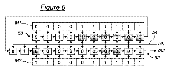
提案しているアーキテクチャは、連なって配置される2つのシフトレジスタ50および52を有する。各シフトレジスタは、最初のセルを除いて、前のセルの出力部「out」に連結する入力部「in」を有するセルからなる。さらに、第2のシフトレジスタ52の最初のセルの入力部「in」は、第1のシフトレジスタ50の最後のセルの出力部に連結している。
The proposed architecture has two
各シフトレジスタの各セルはさらに、クロック信号供給回路54に連結し、この回路によって、out(k)=in(k−1)の関係に応じてクロックkごとに各セルの入力部に出力部に対する桁上げが生じてレジスタ50および52の内容を順に読み取る。最後に、元の方法により、各シフトレジスタの各セルは、このセルがたとえば「1」のときに短絡することが可能となる追加の制御入力部を有する。換言すると、この短絡が1つのセルに対して作動すると、out(k)=in(k)およびこのセルによってもたらされた値は読み取られない。
Each cell of each shift register is further connected to a clock
図6に示した特殊なアーキテクチャは、10ビットの符号語および1符号ビットの符号語の変換に適応される。このアーキテクチャは符号語「s0000010110」を処理する特殊な場合であり、その符号変換は前述のとおりである。 The special architecture shown in FIG. 6 is adapted for conversion of 10-bit codewords and 1-codebit codewords. This architecture is a special case of processing the code word “s0000010110”, and the code conversion is as described above.
第1のシフトレジスタ50は、処理する符号語の値のビット数と同数のセル、つまり10個のセルを有する。このセルは符号語の値でロードされ、最初のセルは最も重みの小さいビットを有し、最後のセルは最も重みの大きいビットを有する。
The
第2のシフトレジスタ52は、第1のシフトレジスタのほかに2つのセルを有する。その最初の2つのセルはそれぞれ符号語の符号ビットおよび「1」でロードされる。あとの10個のセルは「0」でロードされる。
The
当然ながら、補足の論理または選択した規定では、使用したエントロピー符号化の変形例に応じてレジスタのセルの値を適応させる。 Of course, supplemental logic or selected conventions adapt the values of the register cells depending on the entropy coding variant used.
第1のシフトレジスタ50の10個のセルの制御入力部は、それぞれ第1の短絡の符号語M1から10ビットを取り込む。第2のシフトレジスタ52の「0」でロードされた10個のセルの制御入力部は、それぞれ第2の短絡の符号語M2から10ビットを取り込む。
The 10 cell control inputs of the
第1および第2の符号語M1およびM2は、Bの値および変換する符号語の最も重みの大きい「1」のビットのnの位置を基に定義される。 The first and second codewords M1 and M2 are defined based on the value of B and the position of n of the “1” bit having the largest weight of the codeword to be converted.
そのため、第1の中間語Mi1を2進形式および10ビットで値2B−1と定義する。たとえば、Bの値が2であれば、Mi1の値は「0000000011」となる。また、第2の中間語Mi2も2進形式および10ビットで値2n−1と定義する。たとえば、符号語「s0000010110」に対しては、nの値は5である。よってMi2の値は「0000011111」となる。また、Mi2/2の値は「0000001111」であることもわかり、これはMi2の重みの小さいビットの方へ1つシフトさせたものに相当する。
Therefore, the first intermediate word Mi1 is defined as a
実際には、第2の中間語Mi2は変換する符号語から容易に得られる。最も重みの大きいビットを、変換する符号語の最も重みの大きいビット値にし、変換する符号語のn番目のビットとn−1番目のビットとの間を論理和(OR)の関係を用いて重みの小さいビットに向かって繰り返し下がり、n−1番目のビット値を決定する。 In practice, the second intermediate word Mi2 is easily obtained from the codeword to be converted. The bit with the highest weight is set to the bit value with the highest weight of the codeword to be converted, and the nth bit and the (n−1) th bit of the codeword to be converted are used in a logical sum (OR) relationship. Decreasing repeatedly toward the bit with the smaller weight, the (n-1) th bit value is determined.
第1の符号語M1は、次の論理的関係によって定義される。
M1=NOT(Mi2/2 OR Mi1)。
The first code word M1 is defined by the following logical relationship.
M1 = NOT (Mi2 / 2 OR Mi1).
図6に示す例では、以下のようになる。
M1=NOT(「0000001111」OR「0000000011」)、
M1=NOT(「0000001111」)、M1=「1111110000」。
In the example shown in FIG.
M1 = NOT (“0000001111” OR “0000000011”),
M1 = NOT (“0000001111”), M1 = “1111110000”.
第2の符号語M2は、次の論理的関係によって定義される。
M2=(NOT Mi2)OR Mi1。
The second code word M2 is defined by the following logical relationship.
M2 = (NOT Mi2) OR Mi1.
図6に示す例では、以下のようになる。
M2=(NOT「0000011111」)OR「0000000011」、
M2=「1111100000」OR「0000000011」、
M2=「1111100011」。
In the example shown in FIG.
M2 = (NOT “0000001111”) OR “0000000011”,
M2 = "1111100000" OR "0000000011",
M2 = "1111100011".
図6では、符号語M1およびM2は、左から右に向かってビットの重みが増加するように示している。「1」のビットがあるごとに、グレーで示した該当セルを短絡する。2つの連続するシフトレジスタによって伝送されていないグレーのセルの値は、第2のレジスタ52の最後のセルを第1のレジスタ50の最初のセルまで上げると、第2のシフトレジスタ52の出力部から順に供給された変換後の符号語は、この例では値「0001s0110」となることがわかる。
In FIG. 6, codewords M1 and M2 are shown such that the bit weight increases from left to right. Each time there is a “1” bit, the corresponding cell shown in gray is short-circuited. The value of a gray cell that is not transmitted by two successive shift registers increases the output of the
前述したようなエントロピー符号化を使用することによる符号語変換を改良した方法は、無相関化した値を持つがノイズの入っている2進データ列が存在するとしても、高性能を維持できることは明らかである。 The method of improving the codeword conversion by using the entropy coding as described above can maintain high performance even when there is a binary data sequence having a decorrelated value but containing noise. it is obvious.
さらに、Bの値が2進データ列を抽出した統計データを基に自動計算されると、この符号変換方法はそれに適応するようになり、これは特に有利な点である。パラメータBが十分小さい値を取るようにすると(つまり、ノイズレベルを先験的にノイズに埋もれたビット数に量子化する)、このパラメータをさらに小さいビット数(たとえば3)に対して符号化することができる。よって、この符号変換方法に適応特性を追加した分は問題にならない。また、Bの値は特別な統計計算をしなくても先験的に決定することができることもわかる。 Further, when the value of B is automatically calculated based on statistical data obtained by extracting a binary data string, this code conversion method is adapted to it, which is a particularly advantageous point. If the parameter B is set to a sufficiently small value (ie, the noise level is quantized to the number of bits buried in noise a priori), this parameter is encoded for a smaller number of bits (eg, 3). be able to. Therefore, the addition of adaptive characteristics to this code conversion method does not matter. It can also be seen that the value of B can be determined a priori without special statistical calculations.
つまり、重要な点は、図5および図6を参照して説明した本発明の第2の局面は、本発明によるブロックごとの符号化方法に適用され、特に図1〜図4(本発明の第1の局面)を参照して説明した実施形態に適用されることが有利であるという点である。 That is, the important point is that the second aspect of the present invention described with reference to FIGS. 5 and 6 is applied to the block-by-block encoding method according to the present invention. It is advantageous to be applied to the embodiment described with reference to the first aspect).
ただし、当業者は、本発明による第1の局面の方法によって必然的に符号化したデータを入力部に供給することなく実践することができる限り、本発明の第2の局面が第1の局面とは別のものであることは理解できるであろう。本方法は、ブロックごとに符号化するほかの方法にも有利なように適用することができ、たとえば先行技術に記載の方法など、最初に強く相関化していた画像、映像または音声の信号を最終的に無相関化する方法に適用することができる。 However, as long as those skilled in the art can practice the data encoded by the method of the first aspect according to the present invention without supplying it to the input unit, the second aspect of the present invention is the first aspect. It will be understood that this is different. The method can also be applied to other methods of encoding block by block, such as the method described in the prior art, for the final strongly correlated image, video or audio signal. This method can be applied to a method of automatically decorrelating.
逆に、本発明の第1の局面に沿って説明した符号化方法は、必ずしもこの符号変換方法を含む必要はなく、周知の符号変換方法を使用してもよい。 Conversely, the encoding method described along the first aspect of the present invention does not necessarily include this code conversion method, and a known code conversion method may be used.
Claims (10)
− 各ブロックの横の画素数を表す水平寸法Pは、pの倍数であるためP=k.pと定義し、解像度logp(P)での分割を水平方向に分割する1次元カーネルを用いて実行し、
− 各ブロックの縦の画素数をN表す垂直寸法Nは、nの倍数であるためN=l.nと定義し、解像度logn(N)での分割を垂直方向に分割する1次元カーネルを用いて実行する符号化方法において、
所与のnおよびpの値に対し、前記垂直寸法Nが前記水平寸法Pよりも小さくなるように前記kおよびlの値を選択することを特徴とする符号化方法。
A block- by- block encoding method (14) of a pixel raster image composed of a plurality of independent blocks, a one-dimensional kernel for dividing n pixels in the vertical direction and a one-dimensional kernel for dividing p pixels in the horizontal direction Are applied in combination with the predetermined discrete function bases (LL1, HL1, LH1, HH1, L2, H2, L3, H3, L4, H4) to continuously two-dimensionally partition the block of the image (100 , 102, 104), wherein the horizontal direction of the block is defined as the direction of the rows of the raster image in the mode of reading one line at a time and / or the mode of transmitting,
The horizontal dimension P representing the number of pixels next to each block is a multiple of p, so P = k. p is defined, and the division at resolution log p (P) is performed using a one-dimensional kernel that divides in the horizontal direction,
The vertical dimension N representing the number of vertical pixels in each block is a multiple of n, so N = 1. In an encoding method that is defined as n and that uses a one-dimensional kernel to divide the resolution log n (N) in the vertical direction,
An encoding method, wherein the values of k and l are selected such that the vertical dimension N is smaller than the horizontal dimension P for a given value of n and p.
− 画像ブロックを連続的に2次元分割する前記ステップ(100、102、104)に続いて、符号変換する語で構成される第1の2進データ列を供給するステップ(200)と、
− 所定の可変長符号のエントロピー符号を用いて(208)、第1の2進データ列を圧縮した第2の2進データ列にエントロピー的に符号変換し(202、204、206、208、210、212)、前記第1の2進データ列の各符号語を変換後の符号語に変換するステップ
とを含み、
前記第1の2進データ列の符号語のノイズレベルを表すものと考える重みの小さいビット数をBと表記する所定数をベースとして、前記第1の2進データ列の各符号語に、
− 符号語を第1および第2のサブ符号語に細分化して(206)、前記第1のサブ符号語が符号語の重みの小さいBビットを有し、前記第2のサブ符号語が符号語の重みの大きい別のビットを有するようにするステップと、
− 所定のエントロピー符号を前記第2のサブ符号語に適用して変換後の第2のサブ符号語を得るステップ(208)と、
− 前記変換した第1のサブ符号語と第2のサブ符号語を連結させることによって前記変換後の符号語を得るステップ(210)とを適用する段階を含む、請求項1〜4のいずれか一項に記載の符号化方法。 The encoding method further includes the step (100, 102, 104) of continuously dividing the image block into two dimensions, and supplying a first binary data string composed of words to be transcoded ( 200),
-Entropy-converts the first binary data string into a compressed second binary data string (202, 204, 206, 208, 210) using an entropy code of a predetermined variable length code (208). 212), converting each codeword of the first binary data string into a converted codeword,
Based on a predetermined number expressed as B, the number of bits with a small weight that is considered to represent the noise level of the code word of the first binary data sequence, to each code word of the first binary data sequence,
Subdividing the codeword into first and second subcodewords (206), wherein the first subcodeword has B bits with low codeword weight, and the second subcodeword is code Having another bit with a higher word weight;
Applying a predetermined entropy code to the second subcodeword to obtain a transformed second subcodeword (208);
Applying the step (210) of obtaining the transformed codeword by concatenating the transformed first subcodeword and second subcodeword. The encoding method according to one item.
− 連続する最初のN−1行を読み取り、記憶するステップ(100)と、
− N番目の行のデータを取得する間に、該行の少なくとも1つのブロックの2次元分割を実行するステップ(102、104)
とを含む、請求項6に記載の符号化方法。 While the encoding method further reads N consecutive rows,
Reading and storing the first consecutive N-1 rows (100);
Performing two-dimensional partitioning of at least one block of the row (102, 104) while acquiring data of the Nth row
The encoding method according to claim 6, including:
Applications Claiming Priority (3)
| Application Number | Priority Date | Filing Date | Title |
|---|---|---|---|
| FR0804892 | 2008-09-05 | ||
| FR0804892A FR2935864B1 (en) | 2008-09-05 | 2008-09-05 | BLOCK ENCODING METHOD OF PIXEL MATRIX IMAGE, COMPUTER PROGRAM AND CORRESPONDING IMAGE CAPTURE DEVICE |
| PCT/FR2009/051677 WO2010026350A1 (en) | 2008-09-05 | 2009-09-04 | Block encoding method for bitmap pixel image, and corresponding computer program and image capture device |
Publications (2)
| Publication Number | Publication Date |
|---|---|
| JP2012502536A JP2012502536A (en) | 2012-01-26 |
| JP5534247B2 true JP5534247B2 (en) | 2014-06-25 |
Family
ID=40622102
Family Applications (1)
| Application Number | Title | Priority Date | Filing Date |
|---|---|---|---|
| JP2011525601A Expired - Fee Related JP5534247B2 (en) | 2008-09-05 | 2009-09-04 | Pixel-by-block encoding method of pixel raster image, computer program thereof, and image capture device thereof |
Country Status (5)
| Country | Link |
|---|---|
| US (1) | US8531544B2 (en) |
| EP (1) | EP2327217B1 (en) |
| JP (1) | JP5534247B2 (en) |
| FR (1) | FR2935864B1 (en) |
| WO (1) | WO2010026350A1 (en) |
Families Citing this family (4)
| Publication number | Priority date | Publication date | Assignee | Title |
|---|---|---|---|---|
| US9270895B2 (en) | 2013-07-31 | 2016-02-23 | Massachusetts Institute Of Technology | Methods and apparatus for true high dynamic range imaging |
| US9866770B2 (en) | 2015-10-21 | 2018-01-09 | Massachusetts Institute Of Technology | Methods and apparatus for true high dynamic range (THDR) time-delay-and-integrate (TDI) imaging |
| KR20210046002A (en) | 2018-09-07 | 2021-04-27 | 주식회사 윌러스표준기술연구소 | Video signal processing method and apparatus using multi-transformation kernel |
| US11064219B2 (en) * | 2018-12-03 | 2021-07-13 | Cloudinary Ltd. | Image format, systems and methods of implementation thereof, and image processing |
Family Cites Families (7)
| Publication number | Priority date | Publication date | Assignee | Title |
|---|---|---|---|---|
| US6757438B2 (en) * | 2000-02-28 | 2004-06-29 | Next Software, Inc. | Method and apparatus for video compression using microwavelets |
| EP0817494A3 (en) * | 1996-06-28 | 1998-07-22 | Oki Electric Industry Co., Ltd. | Image coding method and apparatus |
| US20040136602A1 (en) * | 2003-01-10 | 2004-07-15 | Nithin Nagaraj | Method and apparatus for performing non-dyadic wavelet transforms |
| JP4618676B2 (en) * | 2005-04-28 | 2011-01-26 | 株式会社リコー | Structured document code transfer method, image processing system, server device, program, and information recording medium |
| FR2887711A1 (en) * | 2005-06-23 | 2006-12-29 | Thomson Licensing Sa | METHOD OF ENCODING AND HIERARCHICAL DECODING |
| JP4129694B2 (en) * | 2006-07-19 | 2008-08-06 | ソニー株式会社 | Information processing apparatus and method, program, and recording medium |
| FR2935865B1 (en) * | 2008-09-05 | 2010-10-15 | Commissariat Energie Atomique | METHOD FOR ENTROPTICALLY TRANSCODING A FIRST BINARY DATA TRAIN TO A SECOND COMPRESSED BINARY DATA TRAIN, COMPUTER PROGRAM, AND CORRESPONDING IMAGE CAPTURE DEVICE |
-
2008
- 2008-09-05 FR FR0804892A patent/FR2935864B1/en not_active Expired - Fee Related
-
2009
- 2009-09-04 WO PCT/FR2009/051677 patent/WO2010026350A1/en active Application Filing
- 2009-09-04 EP EP09741374A patent/EP2327217B1/en active Active
- 2009-09-04 US US13/057,860 patent/US8531544B2/en active Active
- 2009-09-04 JP JP2011525601A patent/JP5534247B2/en not_active Expired - Fee Related
Also Published As
| Publication number | Publication date |
|---|---|
| FR2935864B1 (en) | 2011-07-01 |
| EP2327217A1 (en) | 2011-06-01 |
| JP2012502536A (en) | 2012-01-26 |
| EP2327217B1 (en) | 2012-07-04 |
| FR2935864A1 (en) | 2010-03-12 |
| US8531544B2 (en) | 2013-09-10 |
| US20110141310A1 (en) | 2011-06-16 |
| WO2010026350A1 (en) | 2010-03-11 |
Similar Documents
| Publication | Publication Date | Title |
|---|---|---|
| CN110612722B (en) | Method and apparatus for encoding and decoding digital light field images | |
| Zhao et al. | Light field image compression based on deep learning | |
| JP5534247B2 (en) | Pixel-by-block encoding method of pixel raster image, computer program thereof, and image capture device thereof | |
| US20240080481A1 (en) | Sparse matrix representation using a boundary of non-zero coefficients | |
| Aulí-Llinàs et al. | Lossy-to-lossless 3D image coding through prior coefficient lookup tables | |
| US20180205962A1 (en) | Method and apparatus for encoding and decoding images | |
| EP3456044B1 (en) | Method and device for context-adaptive binary arithmetic coding or decoding a sequence of binary symbols representing a syntax element related to video data | |
| US9531915B2 (en) | Image encoding system and method thereof | |
| JP2000341689A (en) | Wavelet inverse converting device and its method and wavelet decoding device and its method | |
| JP5527556B2 (en) | Method for entropically code-converting first binary data string into compressed second binary data string, computer program thereof, and image capture device thereof | |
| US8861880B2 (en) | Image processing device and image processing method | |
| CN110710219B (en) | Method and apparatus for context derivation for coefficient coding | |
| CN109819251B (en) | Encoding and decoding method of pulse array signal | |
| JP2008124530A (en) | Raw data compressing method | |
| EP4294017A1 (en) | Method for image encoding | |
| WO2023197031A1 (en) | Method, apparatus and system for encoding and decoding a tensor | |
| WO2023197032A1 (en) | Method, apparatus and system for encoding and decoding a tensor | |
| WO2023197029A1 (en) | Method, apparatus and system for encoding and decoding a tensor | |
| CN117321989A (en) | Independent localization of auxiliary information in neural network-based image processing | |
| WO2023197030A1 (en) | Method, apparatus and system for encoding and decoding a tensor | |
| WO2023242594A1 (en) | Method for image encoding | |
| WO2023197033A1 (en) | Method, apparatus and system for encoding and decoding a tensor | |
| Cardoso et al. | CMOS imager with current-mode sub-band image coding at the focal plane | |
| EP1345169A2 (en) | Method and apparatus for image reduction | |
| JP2004056575A (en) | Moving image encoding device, moving image decoding device and their methods |
Legal Events
| Date | Code | Title | Description |
|---|---|---|---|
| A621 | Written request for application examination |
Free format text: JAPANESE INTERMEDIATE CODE: A621 Effective date: 20120808 |
|
| A977 | Report on retrieval |
Free format text: JAPANESE INTERMEDIATE CODE: A971007 Effective date: 20130729 |
|
| A131 | Notification of reasons for refusal |
Free format text: JAPANESE INTERMEDIATE CODE: A131 Effective date: 20130910 |
|
| A601 | Written request for extension of time |
Free format text: JAPANESE INTERMEDIATE CODE: A601 Effective date: 20131210 |
|
| A602 | Written permission of extension of time |
Free format text: JAPANESE INTERMEDIATE CODE: A602 Effective date: 20140107 |
|
| A521 | Written amendment |
Free format text: JAPANESE INTERMEDIATE CODE: A523 Effective date: 20140110 |
|
| TRDD | Decision of grant or rejection written | ||
| A01 | Written decision to grant a patent or to grant a registration (utility model) |
Free format text: JAPANESE INTERMEDIATE CODE: A01 Effective date: 20140401 |
|
| R150 | Certificate of patent or registration of utility model |
Ref document number: 5534247 Country of ref document: JP Free format text: JAPANESE INTERMEDIATE CODE: R150 |
|
| A61 | First payment of annual fees (during grant procedure) |
Free format text: JAPANESE INTERMEDIATE CODE: A61 Effective date: 20140415 |
|
| R250 | Receipt of annual fees |
Free format text: JAPANESE INTERMEDIATE CODE: R250 |
|
| R250 | Receipt of annual fees |
Free format text: JAPANESE INTERMEDIATE CODE: R250 |
|
| R250 | Receipt of annual fees |
Free format text: JAPANESE INTERMEDIATE CODE: R250 |
|
| LAPS | Cancellation because of no payment of annual fees |