JP5529638B2 - Audio processing apparatus, audio processing method, and imaging apparatus - Google Patents
Audio processing apparatus, audio processing method, and imaging apparatus Download PDFInfo
- Publication number
- JP5529638B2 JP5529638B2 JP2010137678A JP2010137678A JP5529638B2 JP 5529638 B2 JP5529638 B2 JP 5529638B2 JP 2010137678 A JP2010137678 A JP 2010137678A JP 2010137678 A JP2010137678 A JP 2010137678A JP 5529638 B2 JP5529638 B2 JP 5529638B2
- Authority
- JP
- Japan
- Prior art keywords
- noise
- drive
- microphone
- unit
- audio signal
- Prior art date
- Legal status (The legal status is an assumption and is not a legal conclusion. Google has not performed a legal analysis and makes no representation as to the accuracy of the status listed.)
- Expired - Fee Related
Links
Images


Description
本発明は、音声処理技術に関する。 The present invention relates to a voice processing technique.
従来より、被写体等の音声記録時に混入した雑音を取り除くための音声処理技術が数多く提案されている。上記音声記録時に混入する雑音の1つとして、風による雑音(以下、風雑音)が挙げられる。これは、マイクロホンの振動板が風による空気の変動を音声信号として取得してしまう現象であり、1kHz以下の低周波数帯域において顕著に見られる。この風雑音を抑制する技術の1つとして、例えば、特許文献1では、風雑音の影響を受けやすい指向性マイクと、指向性マイクよりも風雑音の影響を受けにくい無指向性マイクとを用いて風雑音の発生を判断し抑制する技術が提案されている。特許文献1によれば、風雑音が発生していると判断すると、指向性マイクで取得される中高周波成分の音声信号と、無指向性マイクで取得される低周波成分の音声信号とを合成することで風雑音の抑制を行っている。 Conventionally, many sound processing techniques for removing noise mixed during sound recording of a subject or the like have been proposed. As one of noises mixed during the voice recording, there is wind noise (hereinafter referred to as wind noise). This is a phenomenon that the diaphragm of the microphone acquires air fluctuations due to wind as an audio signal, and is noticeable in a low frequency band of 1 kHz or less. As one of the techniques for suppressing this wind noise, for example, Patent Document 1 uses a directional microphone that is more susceptible to wind noise and an omnidirectional microphone that is less susceptible to wind noise than a directional microphone. Thus, techniques for determining and suppressing the occurrence of wind noise have been proposed. According to Patent Document 1, when it is determined that wind noise has occurred, a medium-high frequency component audio signal acquired by a directional microphone and a low-frequency component audio signal acquired by an omnidirectional microphone are combined. By doing so, wind noise is suppressed.
一方、音声記録時に混入する他の雑音としてビデオカメラ等の音声記録装置の機械的な駆動音(以下、駆動雑音)が挙げられる。例えば、ビデオカメラ等による音声記録を伴う動画撮影中にズームやフォーカス等のレンズ駆動を行った場合、レンズ駆動に伴うモータ音や駆動機構の摺動音等が駆動雑音として音声信号に混入する。この駆動雑音を低減する技術の1つとして、例えば、特許文献2では、スペクトルサブトラクション(Spectral Subtraction;SS)法と呼ばれる手法を用いて音声信号に混入する駆動雑音の低減を行っている。SS法とは、雑音の混入した音声信号データを周波数領域に変換し、予め用意した雑音のスペクトルを減算する雑音低減処理である。 On the other hand, mechanical noise (hereinafter referred to as drive noise) of an audio recording device such as a video camera can be cited as another noise mixed during audio recording. For example, when lens driving such as zooming or focusing is performed during moving image shooting with audio recording by a video camera or the like, motor sound accompanying the lens driving, sliding sound of the driving mechanism, etc. are mixed into the audio signal as driving noise. As one of the techniques for reducing the drive noise, for example, in Patent Document 2, the drive noise mixed in the audio signal is reduced by using a technique called a spectral subtraction (SS) method. The SS method is a noise reduction process in which voice signal data mixed with noise is converted into a frequency domain, and a noise spectrum prepared in advance is subtracted.
しかしながら、上記特許文献1のように特性の異なる複数のマイクを用いて風雑音を抑制し、且つ上記特許文献2のようにSS法により駆動雑音を低減する場合、次のような問題がある。 However, when wind noise is suppressed using a plurality of microphones having different characteristics as in Patent Document 1 and driving noise is reduced by the SS method as in Patent Document 2, there are the following problems.
各マイクに混入する駆動雑音の雑音スペクトルはマイクの配置やマイクの周囲の構造によって異なるため、2つのマイクで取得されるそれぞれの音声信号に対し、同じ雑音スペクトルを用いて駆動雑音の減算を行った場合、雑音低減性能が低下する。例えば、指向性マイクと無指向性マイクではマイクの構造が異なるため、混入する駆動雑音のスペクトルは大きく異なっている。また特許文献3は、指向性の異なる複数のマイクを有し、マイクごとに設定された雑音スペクトルを用いてSS法により駆動雑音を除去している。 Since the noise spectrum of the drive noise mixed in each microphone differs depending on the microphone arrangement and the structure around the microphone, the drive noise is subtracted using the same noise spectrum for each audio signal acquired by the two microphones. In this case, the noise reduction performance is degraded. For example, since the microphone structures of the directional microphone and the omnidirectional microphone are different, the spectrum of the mixed drive noise is greatly different. Patent document 3 has a plurality of microphones with different directivities, and removes drive noise by the SS method using a noise spectrum set for each microphone.
しかしながら、上記特許文献3では、特性の異なる複数のマイクに応じた雑音スペクトルデータを必要とするため、メモリに記憶しておくべき雑音スペクトルデータ量がマイクの数に比例して増大していき、メモリ容量を圧迫してしまう。 However, in Patent Document 3 above, since noise spectrum data corresponding to a plurality of microphones having different characteristics is required, the amount of noise spectrum data to be stored in the memory increases in proportion to the number of microphones. It will put pressure on the memory capacity.
本発明は、上記課題に鑑みてなされ、その目的は、特性の異なる複数のマイクを用いて雑音を抑制する際に、雑音成分データの増大によるメモリ容量の圧迫を避けつつ、雑音低減性能を維持できる音声処理技術を実現することである。 The present invention has been made in view of the above problems, and its object is to maintain noise reduction performance while avoiding compression of memory capacity due to increase of noise component data when suppressing noise using a plurality of microphones having different characteristics. It is to realize a voice processing technology that can be used.
本発明に係る音声信号処理装置は、駆動に伴い音を発生する駆動部を有する音声処理装置であって、前記装置周囲の音声を集音する第1及び第2のマイクと、前記第2のマイクへの風による雑音の伝播を低減する調整手段と、前記第1及び第2のマイクから入力される音声信号を合成する合成手段と、前記第1のマイクから入力される音声信号と前記合成手段により合成された音声信号のいずれかを選択して出力する出力選択手段と、前記出力選択手段により出力された音声信号に混入した駆動雑音をスペクトルサブトラクション法により低減する駆動雑音処理手段と、前記駆動雑音処理手段においてスペクトルサブトラクション法に用いる前記駆動雑音の駆動雑音スペクトルを算出する駆動雑音スペクトル算出手段と、を備え、前記駆動雑音スペクトル算出手段は、記録媒体から読み出された前記第1のマイクから入力される音声信号に混入した駆動雑音の第1の駆動雑音スペクトルと、所定の算出係数とを用いて前記第2のマイクから入力される音声信号に混入した駆動雑音の第2の駆動雑音スペクトルを算出する。 An audio signal processing apparatus according to the present invention is an audio processing apparatus having a drive unit that generates sound as it is driven. The first and second microphones collect sound around the apparatus, and the second microphone Adjustment means for reducing propagation of noise due to wind to the microphone, synthesis means for synthesizing audio signals input from the first and second microphones, and audio signal input from the first microphone and the synthesis Output selection means for selecting and outputting any of the audio signals synthesized by the means, drive noise processing means for reducing drive noise mixed in the audio signal output by the output selection means by a spectral subtraction method, and Driving noise spectrum calculating means for calculating a driving noise spectrum of the driving noise used in the spectral subtraction method in the driving noise processing means, and comprising the driving noise Spectrum calculation unit, the second microphone by using the first driving noise spectrum of the driving noise mixed in speech signal input from said first microphone read from the recording medium, and a predetermined calculation coefficient The second drive noise spectrum of the drive noise mixed in the audio signal input from is calculated.
本発明によれば、特性の異なる複数のマイクを用いて雑音を抑制する際に、雑音成分データの増大によるメモリ容量の圧迫を避けつつ、雑音低減性能を維持できる。 According to the present invention, when noise is suppressed using a plurality of microphones having different characteristics, noise reduction performance can be maintained while avoiding compression of memory capacity due to increase in noise component data.
以下に、添付図面を参照して本発明を実施するための形態について詳細に説明する。尚、以下に説明する実施の形態は、本発明を実現するための一例であり、本発明が適用される装置の構成や各種条件によって適宜修正又は変更されるべきものであり、本発明は以下の実施の形態に限定されるものではない。 EMBODIMENT OF THE INVENTION Below, the form for implementing this invention with reference to an accompanying drawing is demonstrated in detail. The embodiment described below is an example for realizing the present invention, and should be appropriately modified or changed according to the configuration and various conditions of the apparatus to which the present invention is applied. It is not limited to the embodiment.
[実施形態1]以下、図1乃至図7を参照して、本発明の音声処理装置を撮像装置としてのデジタルビデオカメラに適用した実施形態1について説明する。 [Embodiment 1] Embodiment 1 in which an audio processing apparatus of the present invention is applied to a digital video camera as an imaging apparatus will be described below with reference to FIGS.
<装置構成>先ず、図1を参照して、撮像装置の構成について説明する。図1において、撮像部101は、撮影レンズを介して結像された被写体の光学像をCCDセンサやCMOSセンサ等の撮像素子により光電変換してアナログ画像信号を生成し、生成されたアナログ画像信号をデジタル信号に変換して画像処理部102に送出する。画像処理部102は、入力されたデジタル画像信号に、設定値に応じたホワイトバランスや色、明るさ等を調整する画質調整処理を施し、メモリ103、後述する映像出力部110、表示制御部111及び制御部114に送出する。
<Apparatus Configuration> First, the configuration of the imaging apparatus will be described with reference to FIG. In FIG. 1, an
また、音声入力部104は、内蔵されたマイクまたは音声入力端子を介して接続された外部マイク等により、装置周囲の音声を集音(収音)したアナログ音声信号をデジタル信号に変換して音声処理部105に送出する。音声処理部105は、入力されたデジタル音声信号のレベルの適正化処理、特定周波数の低減処理等の音声に関する処理を行いメモリ103や後述の音声出力部109に送出する。また、撮像装置100は、ワイヤレスマイクから送出されたデジタル音声信号を後述の通信部116で受信している。そして、音声処理部105は、後述する「通信部116から入力されたデジタル音声信号のレベル調整処理」を行い、メモリ103や後述の音声出力部109に送出する。また、音声処理部105は、音声入力部104から入力されたデジタル音声信号と、通信部116から入力されたデジタル音声信号とを合成する合成処理を行う。メモリ103は、画像処理部102や音声処理部105により処理された画像信号や音声信号を一時的に記憶する。
In addition, the
符号化処理部106は、メモリ103に一時的に記憶された画像信号や音声信号を読み出して画像信号や音声信号の符号化を行い、圧縮画像データや圧縮音声データ等を生成し、記録再生部107に送出する。記録再生部107は、記録媒体108に対して、符号化処理部106で生成された圧縮画像データや圧縮音声データその他撮影に関する制御データ等を記録する。ここで、記録媒体108は、圧縮画像データや圧縮音声データ等を記録可能であれば、磁気ディスク、光学式ディスク、半導体メモリ等のあらゆる方式の記録媒体であってよく、複数の記録媒体であってもよい。
The
また、記録再生部107は、記録媒体108に記録された圧縮画像データ、圧縮音声データ、各種データ、プログラムを読み出し(再生し)、読み出した圧縮画像データや圧縮音声データを符号化処理部106に送出する。符号化処理部106は、圧縮画像データや圧縮音声データを一時的にメモリ103に記憶させ、所定の手順で復号し、復号化した音声信号を音声出力部109へ、復号化した画像信号を映像出力部110や表示制御部111に送出する。
The recording / reproducing
音声出力部109は、例えば音声出力端子からなり、撮像装置100に接続されたイヤホンやスピーカ等から音声を出力するために音声信号を送出する。また、音声出力部109は、撮像装置100に内蔵され、音声信号に応じた音声を出力するスピーカであっても良い。映像出力部110は、例えば映像出力端子からなり、撮像装置100に接続された外部ディスプレイ等に映像を表示させるために画像信号を送出する。また、音声出力部109及び映像出力部110は、統合された1つの端子、例えばHDMI(High−Definition Multimedia Interface;登録商標)のような端子であっても良い。また、表示制御部111は、符号化処理部106から送出された画像信号や画像処理部102から送出された画像信号に応じた映像や、撮像装置100を操作するための操作画面(メニュー画面)等を表示部112に表示させる。表示部112は、例えば、液晶ディスプレイ、有機ELディスプレイ、電子ペーパー等の表示デバイスであれば何であっても良い。
The
また、操作部113は、例えば、ボタンやダイヤル等であり、ユーザの操作に応じた指示信号を制御部114に送出する。制御部114は、操作部113から送出された指示信号に基づいて、撮像装置100の各ブロックに制御信号を送出することで、各ブロックを制御する。操作部113は、例えば、電源ボタン、記録開始ボタン、メニュー表示ボタン、決定ボタン、カーソルキー、表示部112の任意の点を指定するためのポインティングデバイス、タッチパネル等である。また、制御部114は、各種の処理(プログラム)を実行するための、例えば、CPU(MPU)、メモリ(DRAM、SRAM)等からなる。
The
バス115は、各種データや制御信号等を撮像装置100の各ブロックに送出するためのものである。
The
通信部116は、外部装置との間で通信を行うもので、例えば、音声信号、画像信号、圧縮音声データ、圧縮画像データ等を送受信する。また、撮影開始や終了コマンド等の、撮影動作のための制御信号その他の情報を送受信する。通信部116は、例えば、赤外線通信モジュール、Bluetooth(登録商標)通信モジュール、無線LAN通信モジュール、WirelessUSB等の無線通信モジュールである。
The
撮像部101は、図2にも示すように、光学系221、撮像素子222、A/Dコンバータ223、光学系221の各要素を駆動する光学系駆動部224、制御部114から駆動信号を受けて光学系駆動部224に駆動指令を出力する駆動制御部225を有する。光学系221は、少なくともフォーカスレンズ、防振レンズ、絞りを含む。
As shown in FIG. 2, the
ここで、本実施形態の撮像装置の動作について説明する。本実施形態の撮像装置100は、ユーザが操作部113の電源ボタンを操作すると、操作部113から制御部114に起動の指示信号が送出される。この起動指示を受けて、制御部114は、不図示の電源供給部を制御して、撮像装置100の各ブロックに対して電源を供給させる。
Here, the operation of the imaging apparatus of the present embodiment will be described. In the
電源が供給されると、制御部114は、例えば、操作部113のモード切り換えスイッチにより設定されたモード(撮影モードや再生モード等)を、操作部113からの指示信号により確認する。
When power is supplied, the
<撮影モード>撮影モードでは、撮像装置100は撮影待機状態でユーザが操作部113の記録開始ボタンを操作することで、撮影を開始し、その間、圧縮画像データと圧縮音声データが、記録媒体108に記録される。そしてユーザが操作部113の撮影終了ボタンを操作することで、撮影を終了し、再び撮影待機状態になる。再生モードでは、ユーザが選択したファイルに関する圧縮画像データと圧縮音声データを記録媒体108から再生して音声出力部109から音声信号を出力し、表示部112に映像を表示させる。
<Shooting Mode> In the shooting mode, the
まず、撮影モードについて説明する。撮影モードが設定されると前述のようにまず、撮影待機状態に設定される。撮影待機状態で、ユーザが操作部113の記録開始ボタンを操作することにより撮影開始の指示信号が送出されると、制御部114は、撮影開始の制御信号を撮像装置100の各ブロックに送出し、以下のような動作を行うように制御する。
First, the shooting mode will be described. When the shooting mode is set, the shooting standby state is first set as described above. When a shooting start instruction signal is sent by the user operating the recording start button of the
撮像部101は、撮影レンズを介して結像された被写体の光学像を撮像素子222により光電変換してアナログ信号に生成し、生成したアナログ画像信号をデジタル画像信号に変換して画像処理部102に送出する。画像処理部102は、入力されたデジタル画像信号の画質調整処理(ホワイトバランスや色、明るさ等)を設定値に応じて処理し、表示制御部111に送出する。表示制御部111は、受信した画像信号に関する映像を表示部112に表示させる。また、画像信号はメモリ103にも出力され、メモリ103に一時的に記憶される。
The
音声入力部104は、マイクにより集音されたアナログ音声信号をデジタル音声信号に変換し、得られたデジタル音声信号を音声処理部105に送出する。音声処理部105は、入力されたデジタル音声信号のレベルの適正化処理、特定周波数の低減処理等を行って音声信号を生成し、音声出力部109に送出する。また、音声信号はメモリ103に一時的に記憶される。このとき、撮像装置100では、レンズ等の駆動に伴う雑音を低減する雑音低減処理を実行する。
The
そして、符号化処理部106は、メモリ103に一時的に記憶された画像信号や音声信号を読み出して所定の符号化を行い、圧縮画像データ、圧縮音声データ等を生成する。そして、制御部114は、これらの圧縮画像データ、圧縮音声データを合成し、データストリームを生成し、記録再生部107に出力する。記録再生部107は、UDF、FAT等のファイルシステム管理のもとに、データストリームを1つの動画ファイルとして記録媒体108に書き込んでいく。
Then, the
以上の動作を撮影中は継続する。そして、ユーザが操作部113の記録ボタンを操作することにより撮影終了の指示信号が制御部114に送出されると、制御部114は、撮影終了の制御信号を撮像装置100の各ブロックに送出し、以下のような動作を行うように制御する。
The above operation is continued during shooting. When the user operates the recording button of the
画像処理部102及び音声処理部105は、それぞれ画像信号、音声信号をメモリ103に送出するの停止する。そして、符号化処理部106は、メモリ103に記憶されている残りの画像信号と音声信号とを読み出して所定の符号化を行い、圧縮画像データ、圧縮音声データ等を生成し、それが終わると動作を停止する。
The
制御部114は、これらの最後の圧縮画像データ、圧縮音声データを合成し、データストリームを生成し、記録再生部107に出力する。
The
記録再生部107は、UDF、FAT等のファイルシステム管理のもとに、データストリームを1つの動画ファイルとして記録媒体108に書き込んでいく。そして、データストリームの供給が停止したら、動画ファイルを完成させて、記録動作を停止させる。
The recording /
制御部114は、記録動作が停止すると、撮影待機状態に移行させるように制御信号を撮像装置100の各ブロックに送出して、撮影待機状態に戻る。
When the recording operation stops, the
また、撮影待機状態では、制御部114は、撮像装置100の各ブロックに以下のような動作を行うように制御する。
Further, in the shooting standby state, the
画像処理部102は、画像信号を表示制御部111に送出し、表示部112に画像信号に応じた映像を表示させる。ユーザは、表示部112に映像が表示された画面を見ながら撮影の準備を行う。
The
音声処理部105は、音声信号を音声出力部109に送出する。また、ワイヤレスマイク150から送出されたデジタル音声信号を受信していれば、「通信部116から入力されたデジタル音声信号のレベル調整処理」等を行って音声出力部109に送出する。また、音声処理部105は、音声入力部104により得られた音声信号と通信部116から入力された音声信号とを合成してもよい。
The
そして、得られた音声信号を音声出力部109に送出し、内蔵スピーカや接続されたスピーカまたはイヤホンから音声として出力させる。ユーザは、スピーカやイヤホンから出力される音声を聞きながら操作部113の音量を決定するためのマニュアルボリュームの調整をすることもできる。
Then, the obtained audio signal is sent to the
<再生モード>再生モードでは、制御部114は、再生状態に移行させるように制御信号を撮像装置100の各ブロックに送出し、以下の動作を行うように制御する。
<Reproduction Mode> In the reproduction mode, the
記録媒体108に記録された圧縮画像データと圧縮音声データとからなる動画ファイルを記録再生部107が読み出して、読み出された圧縮画像データ、圧縮音声データを符号化処理部106に送出する。符号化処理部106は、圧縮画像データ、圧縮音声データをメモリ103に一時的に記憶させ、所定の手順で復号し、復号化した音声信号を音声出力部109へ、復号化した画像信号を映像出力部110や表示制御部111に送出する。表示制御部111は、入力された画像信号に応じた映像を表示部112に表示させ、音声出力部109は、入力された音声信号に応じた音声を内蔵されたスピーカや、接続されたイヤホンやスピーカから出力する。
The recording /
以上のように、本実施形態の撮像装置は、画像や音声の記録再生を行う。 As described above, the imaging apparatus according to the present embodiment records and reproduces images and sounds.
<風雑音低減方法>ここで、本実施形態の音声入力部104及び音声処理部105による雑音低減処理のうち、風雑音の低減方法について説明する。
<Wind Noise Reduction Method> Here, of the noise reduction processing by the
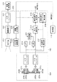
図2は、図1の撮像部101、音声入力部104、音声処理部105の詳細な構成を示すブロック図である。装置本体の外装面206にはマイク孔205a,bが設けられ、マイク孔205a,bの背面にはマイク支持部材202a,bでそれぞれフローティング支持された第1のマイク201aと第2のマイク201bが配設されている。また、外装面206にはマイク孔205bを覆う位置に弾性体であるフィルム203が接着されている。フィルム203は薄膜状で通気性を持たない樹脂製材料で形成されており、1次の共振周波数が500Hz以上であることが望ましい。これは風雑音が500Hz以下で発生することに起因したもので、詳細は後述する。本実施形態では弾性体にポリイミドフィルムを用い、1次の共振周波数が約1.5kHzである形状に加工したものを使用している。
FIG. 2 is a block diagram illustrating detailed configurations of the
フィルム203は、マイク孔205bを密閉し、マイク201bへの空気の移動を調整する弾性体で構成されていて、フィルム203によりマイク孔205bは密閉され、風による空気の移動が遮断される。マイク孔205bを密閉し、マイク201bへの空気の移動を調整する弾性体で構成されるフィルム203を調整機構と定義する。
The
第1のマイク201aは高域通過フィルタ処理を行うハイパスフィルタ(HPF)213に繋がれており、第2のマイク201bは低域通過フィルタ処理を行うローパスフィルタ(LPF)214に繋がれている。HPF213及びLPF214のカットオフ周波数は共に1kHzに設定されている。HPF213とLPF214の出力は合成部211において加算される。
The
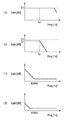
次に、図3を参照して、第1及び第2のマイク201a,201bの集音特性について説明する。図3は第1及び第2のマイク201a,201bの取得音声信号の周波数特性を模式的に表したものであり、それぞれ横軸に周波数〔Hz〕を縦軸にゲイン〔dB〕をとる。第1のマイク201aの被写体音集音時の周波数特性は図3(a)で示すように可聴帯域においてほぼフラットな特性になる。一方、図3(b)はフィルム203によってマイク孔205bが密閉されている第2のマイク201bの被写体音集音時の周波数特性を示している。低周波帯域では第1のマイク201aと比較するとG1[dB]からG2[dB]と少しGainが下がりつつもフラットな特性だが、フィルム203の1次の共振周波数fs1を境に高周波帯域では著しく特性が落ちる。これは、弾性体であるフィルム203が被写体音による高周波帯域の空気の振動を吸収してしまうためである。
Next, the sound collecting characteristics of the first and
図3(c)は第1のマイク201aに対して所定のレベルの風に起因するの風雑音に対する周波数特性を示しており、風雑音が約500Hz以下の低周波帯域で発生していることを示している。図3(d)は第2のマイク201bに対して所定のレベルの風に起因するの風雑音に対する周波数特性を示しており、図3(c)に比べると風雑音が大きく減衰されていることを示している。これは、フィルム203によりマイク孔205bが密閉されているため、風による空気の移動がマイク孔205bから第2のマイク201bまでの空間に伝わらず、第2のマイク201b前方で乱流等の風雑音の原因となる気流の乱れが発生しにくいためである。
FIG. 3C shows the frequency characteristics with respect to the wind noise caused by a predetermined level of wind with respect to the
そこで、風雑音が発生していない場合は、第1のマイク201aの音声信号をそのまま目的音声として取得する。一方、風雑音が発生している場合は、第1のマイク201aの音声信号をHPF213に通過させた信号と、第2のマイク201bの音声信号をLPF214に通過させた信号とを合成する。第1のマイク201aの音声信号はHPF213において1kHz以下の音声信号が減衰処理され、約500Hz以下の風雑音を含む低周波成分が大幅に低減される。一方、第2のマイク201bの音声信号はLPF214において1kHz以上の音声信号が減衰処理されて合成される。これにより、風雑音を大幅に低減することができる。
Therefore, if no wind noise is generated, the audio signal of the
HPF213及びLPF214のカットオフ周波数を同じ値、かつ風雑音が含まれる500Hzから弾性体の1次の共振周波数の範囲に設定することで、合成された音声信号は風雑音を低減しつつも被写体音に対してほぼフラットな周波数特性になっている。例えば、カットオフ周波数を弾性体の1次の共振周波数よりも低い値に設定した場合、LPF214に入力される音声信号はすでに低い弾性体の1次の共振周波数以上で減衰してしまっている。そして、合成された音声信号はカットオフ周波数から弾性体の1次の共振周波数の間の帯域でゲインが落ちてしまう。よって、カットオフ周波数は弾性体の1次の共振周波数よりも大きい値に設定することが望ましい。
By setting the cut-off frequency of the
また、カットオフ周波数が500Hz以下に設定した場合、風雑音は500Hz以下に多く含まれ、HPF213にて第1のマイク201aの音声信号から十分に風雑音が低減できないまま合成されるので、カットオフ周波数は500Hz以上が望ましい。
In addition, when the cut-off frequency is set to 500 Hz or less, wind noise is often included in 500 Hz or less, and the
次に、スペクトルサブトラクション法(以下、SS法)による駆動雑音低減処理について説明する。 Next, driving noise reduction processing by the spectral subtraction method (hereinafter referred to as SS method) will be described.
図4は音声信号を周波数領域に変換したスペクトルを模式的に示すものであり、横軸に周波数、縦軸に各周波数での出力レベルを表している。図4(a)の301は被写体音に駆動雑音が混入した音声信号のスペクトルであり、301は混入した駆動雑音の駆動雑音スペクトルを示している。図4(b)の302は予め取得している駆動雑音スペクトルであり図4(a)の302と同様である。図4(c)の303は駆動雑音の含まれない被写体音のみの音声信号のスペクトルを表している。駆動雑音が混入した音声信号のスペクトル301は駆動雑音スペクトル302と被写体の音声信号スペクトル303が加算されたものに相当する。つまり、取得した音声信号スペクトル301から、駆動雑音スペクトル302を減算すると被写体音声信号スペクトル303となる。このように、レンズ駆動に伴う駆動雑音が発生した場合、予め取得しておいた駆動雑音スペクトルを取得した音声信号のスペクトルから減算することで駆動雑音を低減することができる。そして、駆動雑音スペクトルを減算後の音声信号のスペクトルを時間領域に再変換することで、SS法による駆動雑音低減処理が完了する。
FIG. 4 schematically shows a spectrum obtained by converting an audio signal into the frequency domain, where the horizontal axis represents frequency and the vertical axis represents the output level at each frequency. In FIG. 4A,
次に、図2を参照して、音声処理について説明する。図2において、第1のマイク201aはHPF213と出力選択部212及び風雑音検出部217に繋がれており、同様に第2のマイク201bはLPF214と出力選択部212及び風雑音検出部217に繋がれている。
Next, the audio processing will be described with reference to FIG. In FIG. 2, the
風雑音検出部217では第1及び第2のマイク201a,201bの音声信号を比較することで、風雑音の発生を検出する。風雑音検出部217では、次のようにして風雑音の発生を検出する。風雑音が発生していない時は、第1及び第2のマイク201a,201bの約1kHz以下の低周波帯域の音声信号の音圧レベルの比率は常にほぼ一定である。しかし、風雑音が発生している時は、第1のマイク201aの低周波帯域の音声信号は風雑音により音圧レベルは大きく変化する。一方、第2のマイク201bはマイク孔205bがフィルム203により密閉されているので、風雑音の影響による音圧レベルの変化はほとんど発生しない。よって、第1及び第2のマイク201a,201bの低周波帯域の音圧レベルの比率は激しく変動し、風雑音が発生していない時と比較して異なる値をとる。そこで、第1及び第2のマイク201a,201bの低周波帯域の音圧レベルの比率が音圧レベル閾値を越えた場合は風雑音が発生していると判断する。そして、風雑音検出部217の結果が出力選択部212と駆動雑音スペクトル算出部216に送出される。
The wind
次に、出力選択部212では風雑音検出部217により風雑音が発生していないと判断されると第1のマイク201aの音声信号を選択して駆動雑音処理部215に出力する。一方、風雑音検出部217で風雑音が発生していると判断された場合は、風雑音低減処理された合成部211からの音声信号を選択して出力する。
Next, when the
次に、駆動雑音処理について説明する。駆動雑音処理部215では、制御部114が駆動信号を駆動制御部225に出力すると同時に、雑音低減処理信号を受信する。制御部114から駆動信号が送出されていない時は、雑音低減処理信号も出力されないので駆動雑音が混入していないと判断して、出力選択部212からの音声信号をそのまま音声出力として音声処理部105から出力させる。一方、制御部114から駆動信号が送出された時は、駆動雑音処理部215は音声信号に駆動雑音が混入したと判断し、駆動雑音スペクトル算出部216での算出結果を用いたSS法により駆動雑音低減処理を行う。
Next, drive noise processing will be described. In the drive
次に、駆動雑音スペクトル算出処理について説明する。2種類のマイクを有する場合、光学系駆動部224から各マイクに混入する駆動雑音スペクトルはマイクの配置や周囲の構造によって異なるため、本来はスペクトルそれぞれのマイクの駆動雑音スペクトルのデータを予め取得しておく必要がある。しかし、2種類のマイクの駆動雑音スペクトルのデータを有することは、メモリ容量を圧迫する。特に、雑音低減処理性能を上げるために、周波数領域変換時の分割数を上げるとデータの増加は顕著となる。そこで、本実施形態では駆動雑音スペクトル算出部216において、以下のように駆動雑音スペクトルのデータを算出し記憶する。
Next, drive noise spectrum calculation processing will be described. When there are two types of microphones, the drive noise spectrum mixed into each microphone from the optical
図5(a)の304は第1のマイク201aに混入する第1の駆動雑音スペクトルである。また、305はマイク孔205bを密閉された第2のマイク201bに混入する第2の駆動雑音スペクトルである。第1の駆動雑音スペクトル304のみ、予め測定されて撮像装置100の記録媒体108に記録されている。第1及び第2のマイク201a,201bの配置及び周囲の構造はマイク孔205bがフィルム203により密閉されていること以外はほぼ同一である。よって、図3(a)、(b)で述べたように、第2の駆動雑音スペクトル305はフィルム203の共振周波数f1以下の帯域では第1の駆動雑音スペクトル304から全体的に数dB下がった値となる。一方、共振周波数f1以上の帯域では著しくスペクトルの値が下がる。そこで、風雑音検出部217において風雑音が発生していると判断した場合は、駆動雑音スペクトル算出部216で、図5(b)の306に示す駆動雑音スペクトルを算出し、駆動雑音処理部215に送出する。
駆動雑音スペクトル306はHPF213及びLPF214のカットオフ周波数1kHz以上では、第1の駆動雑音スペクトル304をそのまま用いる。一方、カットオフ周波数1kHz以下では、第1の駆動雑音スペクトル304に所定のスペクトル算出係数αを乗じて算出する。例えば共振周波数f1以下の帯域で第2の駆動雑音スペクトル305が第1の駆動雑音スペクトル304よりも(G1−G2)[dB]下がっていたとすれば、スペクトル算出係数αは式1で表される。
As the driving
(G1−G2)=20log10α
スペクトル算出係数αは、予め周囲音が無音に近い時に、実際に光学系駆動部224を駆動させて、第1及び第2のマイク201a,201bで取得される駆動雑音信号から算出されている。
(G1-G2) = 20 log 10 α
The spectrum calculation coefficient α is calculated in advance from drive noise signals acquired by the first and
風雑音検出部217において風雑音が発生しないと判断された場合は、出力選択部212で選択された出力は第1のマイク201aのそのままの音声信号のため、第1の駆動雑音スペクトル304を駆動雑音処理部215に送出する。
When the wind
駆動雑音処理部215では、駆動雑音スペクトル算出部216からの駆動雑音スペクトルのデータを用いてSS法により駆動雑音の低減処理を行う。駆動雑音処理部215において、駆動雑音低減処理後、再度時間領域変換された信号が音声出力として音声処理部105から出力される。
The drive
このように、風雑音低減のためのマイク孔205bをフィルム203で密閉された第2のマイク201bのカットオフ周波数以下の駆動雑音スペクトルを第1の駆動雑音スペクトル304に所定のスペクトル算出係数αを乗じて算出する。
In this way, the driving noise spectrum below the cutoff frequency of the
そして、風雑音低減処理後、SS法により駆動雑音低減処理を行う際には、次のように駆動雑音スペクトルを算出する。まず、第1の駆動雑音スペクトル304をカットオフ周波数以下の帯域では第1の駆動雑音スペクトル304にスペクトル算出係数αを乗じて算出した結果を用いる。そして、カットオフ周波数以上の帯域では第1の駆動雑音スペクトル304をそのまま用いる。また、風雑音が発生していないときは第1の駆動雑音スペクトル304をそのまま用いる。これにより、風雑音低減処理を行うために、2種類のマイクを有する場合においても、2つのマイクの駆動雑音スペクトルのデータを保持するのではなく、1つのマイクの駆動雑音スペクトルとスペクトル算出係数αを保持するだけで済む。その結果、データ量の増加による記憶容量の圧迫を抑えつつも高品質な駆動雑音低減処理を行うことができる。
Then, after the wind noise reduction process, when the drive noise reduction process is performed by the SS method, the drive noise spectrum is calculated as follows. First, the first
本実施形態では、風雑音検出部217での検出結果により出力選択部212で選択された風雑音低減処理後の音声信号に対して、駆動雑音処理部215で駆動雑音低減処理を行ったが、次のようにしても良い。
In this embodiment, the driving noise reduction processing is performed by the driving
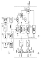
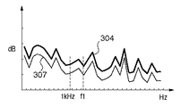
図6は駆動雑音処理を風雑音低減処理より前に行う場合の音声処理部のブロック図である。この場合は、駆動雑音スペクトル算出部216は第1及び第2の駆動雑音処理部215a,bのそれぞれに駆動雑音スペクトルのデータを送出する。駆動雑音処理部215aに送出される駆動雑音スペクトルのデータは第1のマイク201aの第1の駆動雑音スペクトル304そのものである。そして、第2の駆動雑音処理部215bに送出される駆動雑音スペクトルのデータは図7の307のように第1の駆動雑音スペクトル304の全帯域にスペクトル算出係数αを乗じて算出される。算出された駆動雑音スペクトル307は図5(a)で示した第2のマイク201bの第2の駆動雑音スペクトル305に対して、カットオフ周波数以上の帯域で正確ではない。しかし、第2の駆動雑音処理部215bで処理後の音声信号はLPF214によって、カットオフ周波数以上の帯域が減衰されるので、全帯域にスペクトル算出係数αを乗じても良い。
FIG. 6 is a block diagram of the voice processing unit when the driving noise processing is performed before the wind noise reduction processing. In this case, the drive noise
また、駆動雑音処理部215は制御部114から駆動信号が送出されていないと判断した場合は、入力された音声信号をそのまま出力していたが、常に入力された音声信号に対してSS法による処理を行っても良い。駆動雑音処理部215では入力された音声信号を常に周波数領域に変換し音声信号スペクトルを得る。そして、駆動雑音スペクトル算出部216で算出された駆動雑音スペクトルを周波数領域に変換した音声信号スペクトルから減算する。その後、減算されたスペクトルを時間領域に変換し音声信号を出力する。駆動雑音スペクトル算出部216は、駆動制御部225から駆動指令が送出されて駆動雑音が混入していると判断すると、スペクトル算出係数αを用いて図5(b)の雑音スペクトル306を算出し、算出したスペクトルデータを駆動雑音処理部215に送出する。一方、駆動制御部225から駆動指令が送出されていない場合は、駆動雑音スペクトルのデータをゼロとして駆動雑音処理部215に送出する。駆動雑音スペクトルのデータがゼロとは駆動雑音スペクトルを式2のように、W(f)で表すとき、w1,w2,w3,…,wnの値が全て0であることを示す。
In addition, when the drive
W(f)=(w1,w2,w3,…,wn)
なお、式2のwnは周波数領域に変換した際の各周波数帯域でのスペクトルの値である。駆動雑音スペクトルとしてゼロを受けて駆動雑音処理部215では減算が行われ、再度時間領域への変換が行われる。つまり、出力選択部212からの音声信号がSS処理をされても変化することなく、駆動雑音処理部215から出力されることとなる。
W (f) = (w 1 , w 2 , w 3 ,..., W n )
Note that w n in Expression 2 is a spectrum value in each frequency band when converted to the frequency domain. In response to receiving zero as the driving noise spectrum, the driving
また、本実施形態では風雑音検出部217で第1及び第2のマイク201a,201bの音声信号を比較することで風雑音を検出し、検出結果を出力選択部212と駆動雑音処理部215に送出していたが、ユーザが撮影時に風雑音発生の有無を指示しても良い。ユーザは屋外撮影において、風雑音の混入しそうな風が発生していると判断すると、表示部112を見ながら不図示の操作ボタンを操作する。
In this embodiment, the wind
本実施形態では録音機能を有する撮影装置について説明したが、駆動雑音を発生する駆動部を持つものであれば、他の装置として、例えば、磁気ディスク記憶装置を持ち、マイクにより音声を取得するボイスレコーダ等にも本発明は適用可能である。 In this embodiment, the photographing apparatus having a recording function has been described. However, as long as it has a drive unit that generates drive noise, as another apparatus, for example, a voice that has a magnetic disk storage device and acquires sound by a microphone. The present invention can also be applied to a recorder or the like.
[実施形態2]次に、図2及び図8を参照して、実施形態2の音声処理について説明する。実施形態1では、光学系駆動部224による駆動雑音を低減するために、スペクトル算出係数αを用いて駆動雑音スペクトルを算出していた。これに対して、実施形態2は、光学系駆動部224が複数の駆動部(フォーカスレンズ駆動部、防振レンズ駆動部、絞り駆動部等)を搭載している場合である。この場合、駆動部の種類、駆動部から第1及び第2のマイク201a,201bまでの距離や構造により、駆動部ごとに駆動雑音スペクトルは異なる。また、カットオフ周波数以下の帯域での第1のマイク201aに対する第2のマイク201bの駆動雑音スペクトルのゲイン低下量は、第1及び第2のマイク201a,201bまでの距離や構造により駆動部ごとに若干の違いが出る。
[Embodiment 2] Next, referring to FIG. 2 and FIG. 8, the sound processing of Embodiment 2 will be described. In the first embodiment, the drive noise spectrum is calculated using the spectrum calculation coefficient α in order to reduce the drive noise caused by the optical
これは、駆動雑音が空気を伝播して第1及び第2のマイク201a,201bに伝達する以外に、駆動部の駆動に伴う振動が撮像部101や装置本体(カメラボディ)を伝播し各マイク201a,201bに到達し、この振動音を集音してしまうからである。
This is because the driving noise propagates through the air and is transmitted to the first and
第1のマイク201aの駆動雑音スペクトルから第2のマイク201bの駆動雑音スペクトルを算出する際に、各駆動部について同じスペクトル算出係数αを用いると、第2のマイク201bの低周波帯域の駆動雑音スペクトルを正確に算出できない場合がある。また、駆動部ごとに第1及び第2のマイク201a,201bの駆動雑音スペクトルのデータを保持するということは記憶すべきデータ量の増加を招く。そこで、実施形態2では駆動部ごとにスペクトル算出係数を持たせることで、記憶すべきデータ量を抑えつつも各駆動部ごとに適切な雑音低減処理を行うようにしている。
When calculating the driving noise spectrum of the
実施形態2の撮像装置の構成は実施形態1と同様であるため説明を省略する。 Since the configuration of the imaging apparatus of the second embodiment is the same as that of the first embodiment, the description thereof is omitted.
以下、実施形態2の音声処理について図2を参照して説明するが、出力選択部212までの動作は実施形態1と同じであるため説明を省略する。駆動制御部225から光学系駆動部224に駆動指令が送出されると、駆動雑音スペクトル算出部216にも光学系駆動部224への駆動指令が送出される。
Hereinafter, the audio processing according to the second embodiment will be described with reference to FIG. When a drive command is sent from the
駆動雑音スペクトル算出部216では、フォーカスレンズ駆動時はα_a、絞り駆動時はα_b、防振レンズ駆動時はα_c、というように駆動部ごとにスペクトル算出係数を有している。そして、駆動指令が送出された駆動部の種類に合わせてスペクトル算出係数を選択し、選択した係数を用いて駆動雑音スペクトルを算出する。
The drive noise
例えば、駆動制御部225からフォーカスレンズ駆動部に駆動指令が送出されたとする。駆動雑音スペクトル算出部216では、駆動制御部225から駆動指令が送出された駆動部の種類と風雑音検出部217での検出結果を受けて、駆動雑音スペクトルを算出する。
For example, it is assumed that a drive command is sent from the
図8(a)はフォーカスレンズ駆動部の駆動雑音スペクトルを示している。図中、304aは第1のマイク201aの駆動雑音スペクトル、308aは第2のマイク201bの算出された駆動雑音スペクトルをそれぞれ示している。駆動雑音スペクトル308aは、第1のマイク201aの駆動雑音スペクトル304aのカットオフ周波数以下の帯域にスペクトル算出係数α_aを乗じて算出される。
FIG. 8A shows a driving noise spectrum of the focus lens driving unit. In the figure, 304a represents the drive noise spectrum of the
図8(b)は絞り駆動部、図8(c)は防振レンズ駆動部の駆動雑音スペクトルをそれぞれ示している。図中、304b、304cは第1及び第2のマイク201a,201bの駆動雑音スペクトル、308b、308cは308aと同様に、駆動雑音スペクトル304b,304cにスペクトル算出係数α_b、又はα_cを乗じて算出される。
FIG. 8B shows the driving noise spectrum of the diaphragm driving unit, and FIG. 8C shows the driving noise spectrum of the anti-vibration lens driving unit. In the figure, 304b and 304c are the drive noise spectra of the first and
駆動雑音スペクトル算出部216では、風雑音検出部217より風雑音が発生していると判断されると、駆動雑音処理部215へ算出した駆動雑音スペクトル308aを出力する。一方、風雑音が発生していないと判断された場合は第1のマイク201aの駆動雑音スペクトル304aをそのまま出力する。そして、駆動雑音処理部215では出力選択部212からの音声信号に対して、駆動雑音スペクトル算出部216で算出された駆動雑音スペクトルを用いてSS法により駆動雑音低減処理を行う。そして、雑音低減処理が行われた音声信号が記録される。なお、駆動雑音スペクトル304a〜304cとスペクトル算出係数α_a〜cは、予め測定されて撮像装置の記録媒体に記録されている。スペクトル算出係数α_a、α_b、α_cの各値は実験により求められる。
When the drive noise
実施形態2では駆動部ごとにスペクトル算出係数を持たせ、駆動制御部225から光学系駆動部224に送出された駆動指令に合わせてスペクトル算出係数を選択し、駆動雑音処理部215でSS法に用いる駆動雑音スペクトルを算出している。つまり、駆動部ごとに第1及び第2のマイク201a,201bそれぞれの駆動雑音スペクトルを持つことなく、駆動部ごとの第1のマイク201aの駆動雑音スペクトルと駆動部ごとのスペクトル算出係数を保持するだけで良い。その結果、撮像装置が複数の駆動部を搭載する場合であっても、記憶すべきデータ量を抑えつつも駆動部ごとに適切な雑音低減処理を行うことができる。
In the second embodiment, each drive unit has a spectrum calculation coefficient, the spectrum calculation coefficient is selected in accordance with the drive command sent from the
なお、本実施形態では、マイクとして、通常のマイクと、通常のマイクに対してフィルムを付したものを使用したが、この組み合わせに限られるものではない。特に特性の異なるマイクとしては、フィルムを付したマイクでなくとも、骨伝導マイク等の、風の影響を受けにくいマイクであればどのようなマイクであっても良い。 In this embodiment, a normal microphone and a normal microphone with a film attached thereto are used as the microphone, but the present invention is not limited to this combination. In particular, the microphone having different characteristics may be any microphone as long as it is not easily affected by wind, such as a bone conduction microphone, instead of a microphone with a film attached thereto.
また、本実施形態では、音声処理装置を撮像装置に適用した例を説明したが、音声と共に静止画や動画を記録できる装置であれば、例えば、携帯電話やノートパソコン等、他の如何なる装置であっても良い。 In this embodiment, an example in which a sound processing device is applied to an imaging device has been described. However, any other device such as a mobile phone or a laptop computer can be used as long as it can record still images and moving images together with sound. There may be.
本実施形態では、音声信号の雑音低減処理について、音声処理部105で実行するように記載したが、この処理を制御部114で実行しても良い。
In the present embodiment, the audio signal noise reduction processing is described as being executed by the
本実施形態では、音声を記録する際に圧縮して記録する例について説明したが、音声圧縮せずに記録するものであっても良い。 In the present embodiment, an example in which audio is compressed and recorded when recording is described. However, the audio may be recorded without being compressed.
[他の実施形態]本発明は、以下の処理を実行することによっても実現される。即ち、上記実施形態の機能を実現するソフトウェア(プログラム)をネットワーク又は各種記憶媒体を介してシステム或いは装置に供給し、そのシステム或いは装置のコンピュータ(又はCPUやMPU等)がプログラムコードを読み出して実行する処理である。この場合、そのプログラム、及び該プログラムを記憶した記憶媒体は本発明を構成することになる。 [Other Embodiments] The present invention is also realized by executing the following processing. That is, software (program) that realizes the functions of the above-described embodiments is supplied to a system or apparatus via a network or various storage media, and a computer (or CPU, MPU, etc.) of the system or apparatus reads and executes the program code. It is processing to do. In this case, the program and the storage medium storing the program constitute the present invention.
Claims (9)
前記装置周囲の音声を集音する第1及び第2のマイクと、
前記第2のマイクへの風による雑音の伝播を低減する調整手段と、
前記第1及び第2のマイクから入力される音声信号を合成する合成手段と、
前記第1のマイクから入力される音声信号と前記合成手段により合成された音声信号のいずれかを選択して出力する出力選択手段と、
前記出力選択手段により出力された音声信号に混入した駆動雑音をスペクトルサブトラクション法により低減する駆動雑音処理手段と、
前記駆動雑音処理手段においてスペクトルサブトラクション法に用いる前記駆動雑音の駆動雑音スペクトルを算出する駆動雑音スペクトル算出手段と、を備え、
前記駆動雑音スペクトル算出手段は、記録媒体から読み出された前記第1のマイクから入力される音声信号に混入した駆動雑音の第1の駆動雑音スペクトルと、所定の算出係数とを用いて前記第2のマイクから入力される音声信号に混入した駆動雑音の第2の駆動雑音スペクトルを算出することを特徴とする音声処理装置。 An audio processing device having a drive unit that generates sound when driven,
First and second microphones for collecting sounds around the device;
Adjusting means for reducing noise propagation due to wind to the second microphone;
Synthesizing means for synthesizing audio signals input from the first and second microphones;
Output selection means for selecting and outputting either the audio signal input from the first microphone and the audio signal synthesized by the synthesis means;
Drive noise processing means for reducing drive noise mixed in the audio signal output by the output selection means by a spectral subtraction method;
Driving noise spectrum calculating means for calculating a driving noise spectrum of the driving noise used in a spectral subtraction method in the driving noise processing means,
The drive noise spectrum calculation means uses the first drive noise spectrum of the drive noise mixed in the audio signal input from the first microphone read from the recording medium and a predetermined calculation coefficient. A speech processing apparatus that calculates a second drive noise spectrum of drive noise mixed in a speech signal input from the two microphones.
前記第2のマイクに前記フィルムが添付されていることを特徴とする請求項1に記載の音声処理装置。 The adjusting means has an elastic resin film,
The audio processing apparatus according to claim 1, wherein the film is attached to the second microphone.
前記風雑音検出手段により風雑音が検出されない場合、前記出力選択手段は前記第1のマイクから入力される音声信号を選択して出力し、風雑音が検出された場合、前記出力選択手段は前記合成手段により合成された音声信号を選択して出力することを特徴とする請求項1に記載の音声処理装置。 Wind noise detection means for detecting the occurrence of wind noise,
When wind noise is not detected by the wind noise detection means, the output selection means selects and outputs an audio signal input from the first microphone, and when wind noise is detected, the output selection means 2. The speech processing apparatus according to claim 1, wherein the speech signal synthesized by the synthesis means is selected and output.
前記第1のマイクから入力される音声信号に混入する各駆動部の駆動雑音スペクトルと算出係数とを有し、
前記駆動雑音スペクトル算出手段は、前記駆動部ごとの駆動雑音スペクトルと算出係数とを用いて前記第2のマイクから入力される音声信号に混入する各駆動部の駆動雑音スペクトルを算出することを特徴とする請求項1に記載の音声処理装置。 A plurality of drive units,
A drive noise spectrum and a calculation coefficient of each drive unit mixed in the audio signal input from the first microphone;
The driving noise spectrum calculating means calculates a driving noise spectrum of each driving unit mixed in an audio signal input from the second microphone using a driving noise spectrum and a calculation coefficient for each driving unit. The speech processing apparatus according to claim 1.
前記第1及び第2のマイクから入力される音声信号を合成する合成工程と、
前記第1のマイクから入力される音声信号と前記合成工程により合成された音声信号のいずれかを選択して出力する出力選択工程と、
前記出力選択工程により出力された音声信号に混入した駆動雑音をスペクトルサブトラクション法により低減する駆動雑音処理工程と、
前記駆動雑音処理工程においてスペクトルサブトラクション法に用いる前記駆動雑音の駆動雑音スペクトルを算出する駆動雑音スペクトル算出工程と、を備え、
前記駆動雑音スペクトル算出工程では、記録媒体から読み出された前記第1のマイクから入力される音声信号に混入した駆動雑音の第1の駆動雑音スペクトルと、所定の算出係数とを用いて前記第2のマイクから入力される音声信号に混入した駆動雑音の第2の駆動雑音スペクトルを算出することを特徴とする音声処理方法。 Device having a driving unit for generating a sound with the drive, and the first and second microphone for collecting the sound of the ambient, and a regulating means for reducing the noise propagation due to wind to the second microphone A voice processing method in which
A synthesizing step of synthesizing audio signals input from the first and second microphones;
An output selection step of selecting and outputting either the audio signal input from the first microphone and the audio signal synthesized by the synthesis step;
A driving noise processing step of reducing driving noise mixed in the audio signal output by the output selection step by a spectral subtraction method;
A driving noise spectrum calculating step of calculating a driving noise spectrum of the driving noise used in a spectral subtraction method in the driving noise processing step,
In the driving noise spectrum calculation step, the first driving noise spectrum of the driving noise mixed in the audio signal input from the first microphone read from the recording medium and a predetermined calculation coefficient are used. A sound processing method, comprising: calculating a second drive noise spectrum of drive noise mixed in a sound signal input from the two microphones.
撮影レンズ、防振レンズ、及び絞りを含む光学系と、
請求項1乃至7のいずれか1項に記載の音声処理装置とを備え、
前記駆動部は、少なくとも前記撮影レンズを駆動するレンズ駆動部、防振レンズを駆動する防振レンズ駆動部、絞りを駆動する絞り駆動部を含むことを特徴とする撮像装置。 Imaging means for capturing an image of a subject;
An optical system including a photographic lens, an anti-vibration lens, and an aperture;
A voice processing device according to any one of claims 1 to 7,
The image pickup apparatus, wherein the drive unit includes at least a lens drive unit that drives the photographing lens, an anti-vibration lens drive unit that drives an anti-vibration lens, and an aperture drive unit that drives an aperture.
Priority Applications (1)
| Application Number | Priority Date | Filing Date | Title |
|---|---|---|---|
| JP2010137678A JP5529638B2 (en) | 2010-06-16 | 2010-06-16 | Audio processing apparatus, audio processing method, and imaging apparatus |
Applications Claiming Priority (1)
| Application Number | Priority Date | Filing Date | Title |
|---|---|---|---|
| JP2010137678A JP5529638B2 (en) | 2010-06-16 | 2010-06-16 | Audio processing apparatus, audio processing method, and imaging apparatus |
Publications (3)
| Publication Number | Publication Date |
|---|---|
| JP2012003021A JP2012003021A (en) | 2012-01-05 |
| JP2012003021A5 JP2012003021A5 (en) | 2013-08-01 |
| JP5529638B2 true JP5529638B2 (en) | 2014-06-25 |
Family
ID=45535075
Family Applications (1)
| Application Number | Title | Priority Date | Filing Date |
|---|---|---|---|
| JP2010137678A Expired - Fee Related JP5529638B2 (en) | 2010-06-16 | 2010-06-16 | Audio processing apparatus, audio processing method, and imaging apparatus |
Country Status (1)
| Country | Link |
|---|---|
| JP (1) | JP5529638B2 (en) |
Families Citing this family (5)
| Publication number | Priority date | Publication date | Assignee | Title |
|---|---|---|---|---|
| JP2011147103A (en) * | 2009-12-15 | 2011-07-28 | Canon Inc | Audio signal processing device |
| JP6877246B2 (en) * | 2017-06-05 | 2021-05-26 | キヤノン株式会社 | Speech processing device and its control method |
| JP6886352B2 (en) * | 2017-06-05 | 2021-06-16 | キヤノン株式会社 | Speech processing device and its control method |
| KR102078842B1 (en) * | 2019-07-23 | 2020-02-19 | (주)미디어디바이스 | Warning broadcast apparatus for tunnel and method thereof |
| JP7451235B2 (en) | 2020-03-06 | 2024-03-18 | キヤノン株式会社 | Imaging device, control method, and program |
Family Cites Families (4)
| Publication number | Priority date | Publication date | Assignee | Title |
|---|---|---|---|---|
| JPH0965482A (en) * | 1995-08-25 | 1997-03-07 | Canon Inc | Sound collecting method and microphone device executing the method |
| JP2006211302A (en) * | 2005-01-28 | 2006-08-10 | Matsushita Electric Ind Co Ltd | Wind noise reduction component |
| JP2006279185A (en) * | 2005-03-28 | 2006-10-12 | Casio Comput Co Ltd | Imaging apparatus, and sound recording method and program |
| JP4639907B2 (en) * | 2005-03-31 | 2011-02-23 | カシオ計算機株式会社 | Imaging apparatus, audio recording method, and program |
-
2010
- 2010-06-16 JP JP2010137678A patent/JP5529638B2/en not_active Expired - Fee Related
Also Published As
| Publication number | Publication date |
|---|---|
| JP2012003021A (en) | 2012-01-05 |
Similar Documents
| Publication | Publication Date | Title |
|---|---|---|
| EP1589754A2 (en) | Information processing apparatus, imaging apparatus, information processing method, and program | |
| JP5529638B2 (en) | Audio processing apparatus, audio processing method, and imaging apparatus | |
| JP5020845B2 (en) | Audio processing device | |
| JP6637926B2 (en) | Voice processing device and control method thereof | |
| JP5538918B2 (en) | Audio signal processing apparatus and audio signal processing system | |
| US8514300B2 (en) | Imaging apparatus for reducing driving noise | |
| JP5349062B2 (en) | SOUND PROCESSING DEVICE, ELECTRONIC DEVICE HAVING SAME, AND SOUND PROCESSING METHOD | |
| KR101121030B1 (en) | Image capturing apparatus | |
| US20080124049A1 (en) | Method for eliminating noise of a motor | |
| JP5839795B2 (en) | Imaging apparatus and information processing system | |
| JP6985821B2 (en) | Speech processing device and its control method | |
| JP2011130134A (en) | Imaging apparatus and imaging system | |
| JP6929137B2 (en) | Speech processing device and its control method | |
| JP5495753B2 (en) | Imaging device | |
| JP5340127B2 (en) | Audio signal processing apparatus and control method of audio signal processing apparatus | |
| JP6886352B2 (en) | Speech processing device and its control method | |
| US20220383890A1 (en) | Apparatus and method | |
| JP6877246B2 (en) | Speech processing device and its control method | |
| JP6931296B2 (en) | Speech processing device and its control method | |
| JP5506471B2 (en) | Imaging device | |
| JP2010134260A (en) | Electronic apparatus and voice processing method | |
| JP2006217111A (en) | Moving image photographing apparatus and method | |
| JP6103803B2 (en) | Audio signal processing device | |
| JP2023026918A (en) | Voice processing unit, control method of voice processing unit, and program | |
| JP5072730B2 (en) | Signal processing device, imaging device |
Legal Events
| Date | Code | Title | Description |
|---|---|---|---|
| A521 | Request for written amendment filed |
Free format text: JAPANESE INTERMEDIATE CODE: A523 Effective date: 20130617 |
|
| A621 | Written request for application examination |
Free format text: JAPANESE INTERMEDIATE CODE: A621 Effective date: 20130617 |
|
| A977 | Report on retrieval |
Free format text: JAPANESE INTERMEDIATE CODE: A971007 Effective date: 20131224 |
|
| A131 | Notification of reasons for refusal |
Free format text: JAPANESE INTERMEDIATE CODE: A131 Effective date: 20140107 |
|
| A521 | Request for written amendment filed |
Free format text: JAPANESE INTERMEDIATE CODE: A523 Effective date: 20140228 |
|
| TRDD | Decision of grant or rejection written | ||
| A01 | Written decision to grant a patent or to grant a registration (utility model) |
Free format text: JAPANESE INTERMEDIATE CODE: A01 Effective date: 20140320 |
|
| A61 | First payment of annual fees (during grant procedure) |
Free format text: JAPANESE INTERMEDIATE CODE: A61 Effective date: 20140417 |
|
| R151 | Written notification of patent or utility model registration |
Ref document number: 5529638 Country of ref document: JP Free format text: JAPANESE INTERMEDIATE CODE: R151 |
|
| LAPS | Cancellation because of no payment of annual fees |