JP5529552B2 - Anti-vibration control device and method - Google Patents
Anti-vibration control device and method Download PDFInfo
- Publication number
- JP5529552B2 JP5529552B2 JP2010004443A JP2010004443A JP5529552B2 JP 5529552 B2 JP5529552 B2 JP 5529552B2 JP 2010004443 A JP2010004443 A JP 2010004443A JP 2010004443 A JP2010004443 A JP 2010004443A JP 5529552 B2 JP5529552 B2 JP 5529552B2
- Authority
- JP
- Japan
- Prior art keywords
- frequency
- phase
- shaking
- break
- signal
- Prior art date
- Legal status (The legal status is an assumption and is not a legal conclusion. Google has not performed a legal analysis and makes no representation as to the accuracy of the status listed.)
- Expired - Fee Related
Links
Images


Landscapes
- Adjustment Of Camera Lenses (AREA)
Description
本発明は、カメラなどの撮像装置に加わる揺れを検出し、その結果に基づいて、手ブレによる画像劣化を軽減する技術に関するものである。 The present invention relates to a technique for detecting shaking applied to an imaging apparatus such as a camera and reducing image deterioration due to camera shake based on the result.
近年のカメラなどの撮像装置においては、手ブレを補正する技術についての研究が進められている。 In recent imaging apparatuses such as cameras, research on a technique for correcting camera shake is in progress.
例えば特許文献1には特定周波数のブレが大きい時はその信号の位相ズレが小さくなるように周波数特性を変更する技術が開示されており、これによりその周波数のブレ補正精度を高めている。 For example, Patent Document 1 discloses a technique for changing frequency characteristics so that the phase shift of a signal is small when a blur at a specific frequency is large, thereby improving the blur correction accuracy of the frequency.
上述の特許文献等に開示された従来技術の位相補償フィルタでは、特定の周波数のぶれに関して、その補正精度を高める事はできるが、より広い帯域におけるブレ補正精度を高める事ができないという問題がある。 The conventional phase compensation filter disclosed in the above-mentioned patent documents and the like has a problem that it is possible to increase the correction accuracy with respect to blurring of a specific frequency, but it is not possible to increase the blur correction accuracy in a wider band. .
本発明は上記問題点を鑑みてなされたものであり、撮像装置の揺れを示す揺れ信号を、手ブレ補正用の信号に処理する際に生じる位相ズレを、手ブレの周波数帯域において補償することにより、精度の高い手ブレ補正を行えるようにすることを目的とする。 The present invention has been made in view of the above problems, and compensates for a phase shift that occurs when a shake signal indicating a shake of an imaging apparatus is processed into a shake correction signal in the frequency band of the shake. Therefore, it is an object to enable highly accurate camera shake correction.
上記目的を達成するために、撮像装置に加わる、予め設定された周波数帯域の揺れを検出して補正する本発明の防振制御装置は、前記撮像装置に加わる揺れを検出する揺れ検出手段と、前記揺れ検出手段から出力された揺れ信号に対して予め決められた第1の折点周波数よりも低い周波数の揺れ信号を減衰する処理を行う処理手段と、前記処理手段によって処理された前記揺れ信号と、前記処理手段によって処理される前の前記揺れ信号との位相ズレを補償する位相補償手段と、前記位相ズレが補償された前記揺れ信号に基づいて、前記撮像装置の揺れを補正する補正手段とを有し、前記位相補償手段は、前記処理手段によって生じた前記位相ズレを相殺するように、前記処理手段によって処理された前記揺れ信号に対して位相を変更し、前記第1の折点周波数と前記予め設定された周波数帯域のうち最も低い周波数との間に、前記処理手段によって処理された前記揺れ信号に対して位相の変更を開始させるための第2の折点周波数が少なくとも1つ設定されている。 In order to achieve the above object, the image stabilization control device of the present invention that detects and corrects a shake in a preset frequency band applied to the imaging device includes a shake detection unit that detects the shake applied to the imaging device, Processing means for attenuating a shake signal having a frequency lower than a predetermined first break frequency with respect to the shake signal output from the shake detection means, and the shake signal processed by the processing means A phase compensation unit that compensates for a phase shift with respect to the shake signal before being processed by the processing unit, and a correction unit that corrects the shake of the imaging device based on the shake signal that has been compensated for the phase shift. has the door, said phase compensation means so as to cancel the phase shift caused by said processing means to change the phase to the sway signal processed by the processing means, prior A second breakpoint for initiating a phase change for the shaking signal processed by the processing means between a first breakpoint frequency and the lowest frequency of the preset frequency band. At least one frequency is set .
撮像装置の揺れを示す揺れ信号を、手ブレ補正用の信号に処理する際に生じる位相ズレを、手ブレの周波数帯域において補償することにより、精度の高い手ブレ補正を行うことができる。 By compensating for a phase shift that occurs when a shake signal indicating a shake of the imaging apparatus is processed into a camera shake correction signal, the camera shake can be corrected with high accuracy.
以下、添付図面を参照して本発明を実施するための最良の形態を詳細に説明する。 The best mode for carrying out the present invention will be described below in detail with reference to the accompanying drawings.
<第1の実施形態>
図1は本発明の第1の実施形態における防振制御装置のブロック図である。図1において、角速度計11は撮像装置に加わる揺れを検出する振動ジャイロなどである。ハイパスフィルタ12(処理手段)は角速度計11から出力される角速度信号(揺れ信号)に重畳されたDC成分や極低周波のノイズを減衰させるハイパス処理を行う。位相補償フィルタ13はハイパスフィルタ12による処理に起因する角速度信号の位相シフトを補償するが、その詳細は後述する。積分フィルタ14(積分手段)はハイパスフィルタ12から出力された角速度信号を積分して角度信号(積分処理された信号)に変換する。ブレ補正部15は積分フィルタからの角度信号に基づいて、ブレを相殺するように駆動される。
<First Embodiment>
FIG. 1 is a block diagram of an image stabilization control apparatus according to the first embodiment of the present invention. In FIG. 1, an
なお、ブレ補正部15は不図示の光学系内に納められ、駆動される事で光学系の光軸を偏向させるブレ補正光学機構や、駆動される事で結像位置を変更する撮像面駆動機構などがある。本発明ではどのようなブレ補正部であっても適用可能であるので、詳細の説明は省略する。また、実際には、積分フィルタ14とブレ補正部15の間には角度信号の利得を光学系の状態に合わせて調整する敏感度調整部や、ブレ補正部15を駆動する駆動回路等が設けられているが、これらの構成は本発明と直接関係が無いので、詳細な説明は省略する。
Note that the
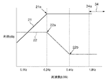
次に、ハイパスフィルタ12と位相補償フィルタ13の構成について図2を参照して説明する。図2はハイパスフィルタ12及び位相補償フィルタ13の利得の周波数特性を模式的に表したボード線図であり、横軸は周波数(対数表記)、縦軸は利得(デシベル表記)を示している。
Next, the configuration of the high-
ハイパスフィルタ12の周波数特性21は、本第1の実施形態では、折点周波数が0.2Hzとなるように折れ点21aを設けたものを使用している。なお、ハイパスフィルタ12の折れ点21aの周波数(第1の折点周波数)は手ブレ周波数帯域34のうち最も低い周波数34aよりも低い周波数であれば良い。このように、入力する角速度信号に、入力する角速度信号の周波数に応じた利得を掛けることにより、0.2Hzより低い周波数の角速度信号は減衰される。図2に示すようなハイパスフィルタ12の周波数特性により、角速度信号に重畳するDC成分や0.2Hz以下の極低周波数成分によるブレ補正精度の劣化を防ぐ。
In the first embodiment, the
一方、位相補償フィルタ13の周波数特性22は、本第1の実施形態では、少なくとも2つの折れ点を有しており、本実施形態では、折点周波数が0.2Hzとなるように折れ点22aを、折点周波数が0.4Hzとなる周波数に折れ点22bを有している。ちなみに、詳細は後述するが、22aは位相を遅らせるように利得の減少を開始する折れ点であり、22bは位相の遅れを無くすように利得の減少を終了する折れ点である。
On the other hand, the
なお、本第1の実施形態では、撮像装置に加わる手ブレの周波数帯域を1Hz〜10Hz程度であるものとしている。図2と図3においては、予め定められた手ブレの周波数帯域のうち、最も低い周波数である1Hzを34a、最も高い周波数である10Hzを34bで表す。図2では34aより高周波側が手ブレ周波数帯域である。また、位相補償フィルタ13の周波数特性22の折れ点22aは、ハイパスフィルタ12の折れ点21aと手ブレ周波数帯域34のうち最も低い周波数34aとの間に設けられていることになる。位相補償フィルタ13の周波数特性22の折れ点22bに関しては、詳しくは後述するが、ハイパスフィルタ12の折れ点21aの周波数よりも大きく、折れ点22aの周波数の1.5倍から3倍の周波数に設けられる。
In the first embodiment, the frequency band of camera shake applied to the imaging apparatus is about 1 Hz to 10 Hz. In FIG. 2 and FIG. 3, among the predetermined frequency bands of camera shake, 1 Hz, which is the lowest frequency, is represented by 34a, and 10Hz, which is the highest frequency, is represented by 34b. In FIG. 2, the higher frequency side than 34a is the camera shake frequency band. Further, the
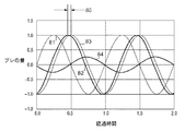
図2に示す周波数特性を有する位相補償フィルタ13を設けた事による効果を、図3を用いて説明する。図3は、図2のボード線図に示す利得の周波数特性を有するハイパスフィルタ12及び位相補償フィルタ13の位相の周波数特性を示したものであり、横軸は周波数(対数表記)、縦軸は位相変化(角度表記)である。
The effect of providing the
利得が変化する周波数帯域(本実施形態においては折れ点21аの折点周波数0.2Hzよりも低い周波数帯域)ではハイパスフィルタ12による位相がシフトする。しかしながら、折れ点21аの折点周波数0.2Hzよりも高い周波数となり、周波数の変化に対して利得が一定になると、次第に位相のシフトは0度に収束していく。図3において、31はハイパスフィルタ12の位相特性であり、折れ点21a(折点周波数が0.2Hz)における位相は45度進んでいる。そして、手ブレ周波数帯域(ここでは、矢印34が示す1Hzから10Hzの範囲)において、例えば1Hzでは位相が11度程度進んでいる。このような位相変化による手ブレ補正の精度劣化について、図4を用いて説明する。
In the frequency band in which the gain changes (in this embodiment, the frequency band lower than the break frequency 0.2 Hz of the
図4は手ブレを模式的に1Hzの正弦波を表した図であり、横軸は経過時間、縦軸はぶれの量(角速度)を表している。 FIG. 4 is a diagram schematically showing a camera shake with a 1 Hz sine wave. The horizontal axis represents elapsed time, and the vertical axis represents the amount of shake (angular velocity).
波形41は角速度計11に加わる実際の角速度の信号波形である。波形42は、その角速度計11からの角速度信号をハイパスフィルタ12で処理し、DC成分や極低周波ノイズを除去した波形である。ここで波形41と波形42を比較すると波形に時間的ズレ43が生じている。これが図3で示した位相11度によるズレである。
A
波形44は波形41と波形42との差であり、これが補正残りによる誤差となる。そのため補正残りによる誤差を少なくする為には、ハイパスフィルタ12による処理前後の位相のズレを小さくすることが必要である。
A
図3に戻って、32は位相補償フィルタ13の位相特性を示しており、折れ点22aの折点周波数と折れ点22bの折点周波数との間で、位相遅れが最大の19度程度となっている。そして、予め定められた手ブレの周波数帯域のうち最も低い周波数である1Hzにおいては10度程度の遅れとなっている。1Hzの手ぶれに着目すると、ハイパスフィルタ12による位相進みが11度程度、位相補償フィルタによる位相遅れが10度程度となるので、互いに位相誤差を相殺する関係になる。
Returning to FIG. 3,
また、手ブレ周波数帯域34における、ハイパスフィルタ12の位相特性31と位相補償フィルタ13の位相特性32のうち、予め定められた手ブレの周波数帯域のうち最も低い周波数34aよりも高い周波数帯域における位相特性を考える。ハイパスフィルタ12の位相特性31と位相補償フィルタ13の位相特性32は、32a近辺での位相特性と、31a近辺での位相特性が互いに略逆の特性となる。そのため、ハイパスフィルタ12の位相特性31と位相補償フィルタ13の位相特性32を合わせた位相特性33は、手ブレ周波数帯域34内では33aに示す様に、位相ズレを極めて少なくすることができる。
Further, of the
ここで、31a近辺でのハイパスフィルタ12の位相特性と、32a近辺での位相補償フィルタ13の位相特性が互いに逆になる理由を説明する。位相特性はフィルタの折点周波数と位相量を計測する周波数との比に基づく。例えばハイパスフィルタ12の折点周波数が0.2Hz、位相量を知りたい周波数が1Hzの場合にはその比に基づいて位相量が計算される。
Here, the reason why the phase characteristic of the high-
ここで、位相補償フィルタ13の位相遅れを開始させる折点周波数を0.2Hzに設定すると、ハイパスフィルタ12と合わせた位相特性の変化は、共に折点周波数が0.2Hzの為、位相が合算されて倍になる。
Here, if the break frequency at which the phase delay of the
一方、位相補償フィルタ13の位相遅れを終了させるための折点周波数を0.4Hzに設定すると1Hzにおいては折点周波数0.2Hzの位相遅れに対して、1Hzと0.4Hzの比の為、倍の位相変化が得られる。その為、折点周波数0.2Hzの位相遅れが二つと折点周波数0.4Hzの位相進みがひとつで相殺し合う事になる。
On the other hand, if the break frequency for terminating the phase lag of the
位相誤差を最も効果的に相殺するのは、上述したように位相補償フィルタ13の位相遅れを開始させるための(低周波側)の折れ点22aをハイパスフィルタ12の折れ点と一致させることである。そして、位相遅れを終了させるための(高周波側)の折れ点22bを位相遅れを開始させるための折れ点の周波数の倍の周波数に設定する事である。しかしながら、パンニングや手ブレ以外の振動、ブレ補正時のメカニカルな摩擦などに対処する為にその設定ができない場合もある。
The most effective cancellation of the phase error is to make the
そこで、位相補償フィルタ13の2つの折れ点22a、22bを様々に変化させ、ハイパスフィルタ12との位相相殺効果を確認した。すると、位相補償フィルタ13の位相遅れを開始させるための折れ点22aの折点周波数がハイパスフィルタ12の折れ点21aの折点周波数に対して約倍或いは半分ずれていても効果がある。例えば、ハイパスフィルタ12の折れ点21aの折点周波数が0.2Hzの時、位相補償フィルタ13の遅れ側折れ点22aの折点周波数は0.1Hzから0.4Hzの間に設定できる。
Therefore, the two
同様に、位相補償フィルタ13の位相遅れを終了させるための折れ点22bの折点周波数は位相遅れを開始させるための折れ点22aの折点周波数に対して1.5倍から3倍に設定しても効果がある。即ち、位相補償フィルタ13の位相遅れを開始させるための折れ点22aの折点周波数を0.2Hzにした時に、位相遅れを終了させるための折れ点22bの折点周波数は0.3Hzから0.6Hzの間に設定できる。
Similarly, the break point frequency of the
以上説明した様に、本第1の実施形態では、ハイパスフィルタ12の折れ点21aの折点周波数と手ブレ周波数帯域34のうち最も低い周波数との間に位相補償フィルタ13の折れ点を設ける。そしてハイパスフィルタ12の折れ点21aの折点周波数と略同じ周波数に位相補償フィルタの位相遅れを開始させるための(低周波側)の折れ点22aを設定し、その略倍の周波数に位相遅れを終了させるための(高周波側)の折れ点22bを設定している。
As described above, in the first embodiment, the break point of the
更に詳細には、ハイパスフィルタ12の折れ点21aに対して、折れ点21aの折点周波数の半分の周波数から倍の周波数の間に位相補償フィルタの位相遅れを開始させるための折れ点22aを設定する。そして折れ点21aの折点周波数の1.5倍から3倍の周波数の間に位相遅れを終了させるための折れ点22bを設定している。
More specifically, a
上記の通り本第1の実施形態によれば、ハイパスフィルタによる位相誤差を位相補償フィルタで相殺することができるため、精度の高いブレ補正を行う事ができる。 As described above, according to the first embodiment, since the phase error due to the high-pass filter can be canceled by the phase compensation filter, it is possible to perform blur correction with high accuracy.
<第2の実施形態>
次に、本発明の第2の実施形態について説明する。図5は本発明の第2の実施形態における防振制御装置のブロック図である。なお、図1と同様の構成には同じ参照番号を付し、ここでは説明を省略する。図5において、51は、積分フィルタ14(積分手段)による積分処理に起因する角度信号(揺れ積分信号)の位相シフトを補償する位相補償フィルタ(位相補償手段、第2の位相補償手段)である。位相補償フィルタ51は、積分フィルタ14(積分手段、第2の処理手段)との間で、位相のズレを相殺している。
<Second Embodiment>
Next, a second embodiment of the present invention will be described. FIG. 5 is a block diagram of an image stabilization control apparatus according to the second embodiment of the present invention. In addition, the same reference number is attached | subjected to the structure similar to FIG. 1, and description is abbreviate | omitted here. In FIG. 5,
次に、位相補償フィルタ51の構成について図6を参照して説明する。図6は積分フィルタ14および位相補償フィルタ51の利得の周波数特性を模式的に表したボード線図であり、横軸は周波数(対数表記)、縦軸は利得(デシベル表記)を示している。61は積分フィルタ14の周波数特性を表しており、本第2の実施形態では、折点周波数が0.2Hzになるように折れ点61aを設けたものを使用している。なお、積分フィルタ14の折れ点61aの周波数(第2の折点周波数)は手ブレ周波数帯域34のうち最も低い周波数34aよりも低い周波数であれば良い。従って、0.2Hzより高い周波数の角速度信号が積分される。ここで周波数に比例して信号が減衰する事を積分特性と呼んでいる。
Next, the configuration of the
位相補償フィルタ51の周波数特性62は、本第2の実施形態では、少なくとも2つの折れ点を有しており、折点周波数0.2Hzに位相遅れを開始させるための折れ点62a、折点周波数0.4Hzに位相遅れを終了させるための折れ点62bを有している。
In the second embodiment, the
なお、本第2の実施形態においても、上述した第1の実施形態と同様に、撮像装置に加わる手ブレの周波数帯域を1Hz〜10Hz程度であるものとしている。図5と図6においては、予め定められた手ブレの周波数帯域のうち、最も低い周波数である1Hzを34a、最も高い周波数である10Hzを34bで表す。図6では34aより高周波側が手ブレ周波数帯域である。また、位相補償フィルタ51の周波数特性62の折れ点62aは、積分フィルタ14の折れ点61aと手ブレ周波数帯域34のうち最も低い周波数34aとの間に設けられていることになる。位相補償フィルタ51の周波数特性62の折れ点62bに関しては、詳しくは後述するが、積分フィルタ14の折れ点61aの折点周波数と同じ若しくは大きく、折れ点62aの折点周波数の1.5倍から3倍の周波数に設けられる。
In the second embodiment as well, as in the first embodiment described above, the frequency band of camera shake applied to the imaging apparatus is about 1 Hz to 10 Hz. In FIG. 5 and FIG. 6, among the predetermined frequency bands of camera shake, 1 Hz, which is the lowest frequency, is represented by 34a, and 10 Hz, which is the highest frequency, is represented by 34b. In FIG. 6, the camera shake frequency band is higher than 34a. Further, the
次に、図6に示す周波数特性を有する位相補償フィルタ51を設けた事による効果を、図7を用いて説明する。図7は、図6のボード線図に示す利得の周波数特性を有する積分フィルタ14及び位相補償フィルタ13の位相の周波数特性を示したものであり、横軸は周波数(対数表記)、縦軸は位相変化(角度表記)である。
Next, the effect of providing the
図7において、71は積分フィルタ14の位相特性である。積分フィルタ14の理論的な積分特性は、元の信号(正弦波とする)に対して90度遅れるが、図7に示す様に折れ点61a(折点周波数が0.2Hz)における位相は45度遅れ足りない。また、手ブレ周波数帯域(ここでは、矢印34が示す1Hzから10Hzの範囲)において、例えば1Hzでは位相が11度程度遅れ足りない。これによる手ブレ補正の精度劣化について、図8を用いて説明する。
In FIG. 7,
図8は手ブレを模式的に1Hzの正弦波で表した図であり、横軸は結果時間、縦軸はぶれの量(角速度)である。 FIG. 8 is a diagram schematically showing camera shake as a sine wave of 1 Hz. The horizontal axis represents the result time, and the vertical axis represents the amount of shake (angular velocity).
波形81は角速度計11に加わる実際の角速度の信号波形である。波形82はその角速度計11からの角速度信号を積分フィルタ14で積分し、角度に変換した波形である。角速度を角度に積分するので、理論的には位相は90度遅れる筈であるが、実際には79度程度の遅れになっている。波形83は角速度計11に加わる角速度を理論的に積分した波形であり、波形82と比較すると時間的ズレ85が生じている。これが図7で示した位相11度によるズレである。
A
波形84は波形82と波形83との差であり、これが補正残りの誤差となる。そのため補正残りによる誤差を少なくする為には、積分フィルタ14による実際の積分結果と積分フィルタ14による理論的な積分結果の位相のズレを小さくすることが必要である。
A
図7に戻って、72は位相補償フィルタ51の位相特性を示しており、折れ点62aの折点周波数と折れ点62bの折点周波数との間で、位相遅れが最大の19度程度となっている。そして、予め定められた手ブレの周波数帯域のうち最も低い周波数である1Hzにおいては10度程度の遅れとなっている。1Hzの手ぶれに着目すると、積分フィルタ14の遅れ足りない位相が11度程度、位相補償フィルタ51の位相遅れが10度程度となるので、互いに位相誤差を相殺する関係になる。
Returning to FIG. 7,
また、手ブレ周波数帯域34における、積分フィルタ14の位相特性71と位相補償フィルタ51の位相特性72の内、予め定められた手ブレの周波数帯域のうち最も低い周波数34aよりも高い周波数帯域における位相特性を考える。積分フィルタ14の位相特性71と位相補償フィルタ51の位相特性72は、72a近辺での位相特性と、71a近辺での位相特性が、互いに略逆の特性となる。そのため、積分フィルタ14の位相特性71と位相補償フィルタ51の位相特性72を合わせた位相特性73は、手ブレ周波数帯域34内では73aに示す様に、位相の遅れ不足を極めて少なくすることができる。
Further, the phase in the frequency band higher than the
なお、71a近辺での積分フィルタ14の位相特性と、72a近辺での位相補償フィルタ51の位相特性が互いに逆になる理由は、第1の実施形態で上述した説明と同じである。
Note that the reason why the phase characteristic of the integrating
位相誤差を最も効果的に相殺するのは、上述したように位相補償フィルタ51の位相遅れを開始させるための(低周波側)の折れ点62aを積分フィルタ14の折れ点と一致させることである。そして、位相遅れを終了させるための(高周波側)折れ点62bの折点周波数を、位相遅れを開始させるための折れ点62aの折点周波数の倍に設定する事である。しかしながら角速度計に重畳する低周波ノイズを増大させてしまう可能性もあり、上記設定ができない場合もある。
The most effective cancellation of the phase error is to match the
そこで、位相補償フィルタ51の2つの折れ点62a、62bを様々に変化させ、積分フィルタ14との位相相殺効果を確認した。すると、位相補償フィルタ51の位相遅れを開始させるための折れ点62aの折点周波数が積分フィルタ14の折れ点61aの折点周波数に対して約倍或いは半分ずれていても効果がある。例えば、積分フィルタ14の折れ点61aの折点周波数が0.2Hzの時、位相補償フィルタ51の位相遅れを開始させるための折れ点62aの折点周波数は0.1Hzから0.4Hzの間に設定できる。
Therefore, the two
同様に位相補償フィルタ51の位相遅れを終了させるための折れ点62bは位相遅れを開始させるための折れ点62aの折点周波数に対して1.5倍から3倍に設定しても効果がある。即ち、位相補償フィルタ51の位相遅れを開始させるための折れ点62aの折点周波数を0.2Hzにした時に、位相遅れを終了させるための折れ点62bの折点周波数は0.3Hzから0.6Hzの間に設定できる。
Similarly, the
以上説明した様に、本第2の実施形態では、積分フィルタ14の折れ点61aの折点周波数と手ブレ周波数帯域34のうち最も低い周波数34aの間に位相補償フィルタ51の折れ点を設ける。そして積分フィルタ14の折れ点61aの折点周波数と略同じ周波数に位相補償フィルタの位相遅れを開始させるための(低周波側)折れ点62aを設定し、その折点周波数の略倍の周波数に位相遅れを終了させるための(高周波側)折れ点62bを設定している。
As described above, in the second embodiment, the break point of the
更に詳細には、積分フィルタ14の折点周波数61aに対して、折れ点61aの折点周波数の半分の周波数から倍の周波数の間に位相補償フィルタの位相遅れを開始させるための折れ点62aを設定する。そして折れ点61aの折点周波数の1.5倍から3倍の周波数の間に位相遅れを終了させるための折れ点62bを設定している。
More specifically, a
上記の通り本第2の実施形態によれば、積分フィルタによる位相誤差を位相補償フィルタで相殺することができるため、精度の高いブレ補正を行う事ができる。 As described above, according to the second embodiment, since the phase error due to the integration filter can be canceled out by the phase compensation filter, blur correction with high accuracy can be performed.
<第3の実施形態>
次に、本発明の第3の実施形態について説明する。図9は本発明の第3の実施形態における防振制御装置のブロック図である。図9に示す防振制御装置では、第1の実施形態で説明したハイパスフィルタ12用の位相補償フィルタ13(第1の位相補償手段)と、第2の実施形態で説明した積分フィルタ14用の位相補償フィルタ51(第2の位相補償手段)を組み合わせたものである。
<Third Embodiment>
Next, a third embodiment of the present invention will be described. FIG. 9 is a block diagram of an image stabilization control apparatus according to the third embodiment of the present invention. In the image stabilization control device shown in FIG. 9, the phase compensation filter 13 (first phase compensation means) for the high-
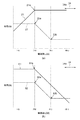
ハイパスフィルタ12及び積分フィルタ14を用いる場合、手ぶれの状態に合わせて、図2に示す折れ点21a及び図6に示す折れ点61aの折点周波数を変更することが行われる。例えば構図を変更する時や、動く被写体を追う撮影を行う(パンニング)時にはハイパスフィルタ12の折点周波数を0.2Hzから2Hzに変更し、同様に積分フィルタ14の折点周波数も0.2Hzから2Hzに変更する。
When the high-
このように折点周波数を高周波側にすると機動性の高い性能にすることができる。しかしながら折点周波数を高周波にするという事はそれだけ手ぶれの周波数帯域の位相ズレを大きくする事になるので、手ぶれ補正性能は劣化してしまう。 As described above, when the corner frequency is set to the high frequency side, high performance can be achieved. However, increasing the corner frequency increases the amount of phase shift in the frequency band of camera shake, and thus the camera shake correction performance deteriorates.
そこで本第3の実施形態においては、ハイパスフィルタ12及び積分フィルタ14の折れ点を変更する時には、各々に対応する位相補償フィルタの折れ点も、ハイパスフィルタ12、積分フィルタ14の折れ点と関係を保ったまま変更する。
Therefore, in the third embodiment, when the break points of the
図10(a)はハイパスフィルタ12、図10(b)は積分フィルタ14の折れ点が、それぞれ変更された後の状態をしており、ハイパスフィルタ12、積分フィルタ14の折点周波数が通常時の0.2Hzから2Hzに変更されている。この時、位相補償フィルタ13、位相補償フィルタ51の特性も位相遅れを開始するための折点周波数(低周波側)を2Hz、位相遅れを終了させるための折点周波数(高周波側)を4Hzに変更して、位相の補償を行う。
10A shows a state after the break point of the high-
図11は第3の実施形態における各フィルタの折れ点変更の手順を示すフローチャートであり、この処理は、例えばカメラなどの撮像装置の主電源オンでスタートする。 FIG. 11 is a flowchart showing a procedure for changing the breakpoint of each filter in the third embodiment, and this process starts when the main power of an imaging apparatus such as a camera is turned on.
先ず、S11において、カメラのレリーズ釦半押し等による、撮影準備の指示があるまで待機する。撮影準備が指示されると、S12で角速度計11の作動を開始し、S13でブレ補正部15によるブレ補正駆動を開始する。
First, in step S11, the process waits until a shooting preparation instruction is issued by pressing the release button of the camera halfway. When the preparation for photographing is instructed, the operation of the
S14では、パンニングが行われたか否かを判定する。例えば、角速度計11の出力、或いはその積分出力が所定期間所定値を越えている場合にパンニングが行われていると判定する。S14でパンニングが行われていると判定されるとS15に進み、そうでなければS17に進む。
In S14, it is determined whether panning has been performed. For example, when the output of the
S15では、ハイパスフィルタ12及び積分フィルタ14の折れ点を、例えばパンニングが行われる前の折点周波数である0.2Hzからパンニング中の折点周波数である2Hzに変更する。続くS16ではハイパスフィルタ12及び積分フィルタ14用の各位相補償フィルタ13、51の位相遅れを開始させるための折れ点を、例えばパンニングが行われる前の折点周波数である0.2Hzからパンニング中の折点周波数である2Hzに変更する。また、位相遅れを終了させるための折れ点をパンニングが行われる前の折点周波数である0.4Hzからパンニング中の折点周波数である4Hzに変更する。
In S15, the break point of the high-
一方、S17では、パンニングが行われていないので、ハイパスフィルタ12及び積分フィルタ14の折点周波数を、例えば、0.2Hz(パンニングが行われる前の折点周波数)とする。つまり、パンニング中の折点周波数が2Hzに設定されていた場合には、パンニング中の折点周波数である2Hzからパンニングが終了した後の折点周波数である0.2Hzに戻し、現状の折点周波数が0.2Hzの場合にはそのままにする。続くS18では、ハイパスフィルタ12及び積分フィルタ14用の各位相補償フィルタ13、位相補償フィルタ51の位相遅れを開始させるための折点周波数を、例えば、0.2Hzとする。つまり、パンニング中に折点周波数が2Hzに設定されていた場合には、パンニング中の折点周波数である2Hzからパンニングが終了した後の折点周波数である0.2Hzに戻し、現状が0.2Hzの場合にはそのままにする。また、位相遅れを終了させるための折れ点の折点周波数を0.4Hzに設定する。つまり、パンニング中に折点周波数が4Hzに設定されていた場合には、パンニング中の折点周波数である4Hzからパンニングが終了した後の折点周波数である0.4Hzに戻し、現状の折点周波数が0.4Hzの場合にはそのままにする。
On the other hand, in S17, since panning is not performed, the break frequency of the high-
S19では、撮影準備指示が解除されたか否かを判定する。解除されていない場合にはS14のパンニング判定に戻り、ブレ補正を継続する。 In S19, it is determined whether or not the shooting preparation instruction has been canceled. If not cancelled, the process returns to the panning determination in S14 and the blur correction is continued.
一方、撮影準備指示が解除されている場合には、S20に進んでブレ補正を停止するとともに、角速度計の作動も停止し、S11に戻る。 On the other hand, if the shooting preparation instruction is cancelled, the process proceeds to S20 to stop the blur correction, and the operation of the angular velocity meter is also stopped, and the process returns to S11.
以上のように本第3の実施形態によれば、ハイパスフィルタ12、積分フィルタ14等の手ブレ信号処理フィルタの折れ点21a、61aの折点周波数と手ブレ周波数帯域34のうち最も低い周波数34aとの間に位相補償フィルタ13、51の折れ点を設ける。そして手ブレ信号処理フィルタの折れ点21a、61aの折点周波数と略同じ周波数に位相補償フィルタの位相遅れを開始させるための(低周波側)の折れ点22a、62aを設定している。さらに、その折点周波数の略倍の周波数に位相遅れを終了させるための(高周波側)の折れ点22b、62bを設定している。
As described above, according to the third embodiment, the
更に詳細には、ハイパスフィルタ12及び積分フィルタ14の折点周波数21a、61aに対してその周波数の半分の周波数から2倍の周波数の間に、位相補償フィルタの位相遅れを開始させるための(低周波側)の折れ点22a、62aを設定する。更に、その1.5倍から3倍の周波数の間に位相遅れを終了させるための(高周波側)の折れ点22b、62bを設定する。
More specifically, a phase delay of the phase compensation filter is started between a frequency half the frequency of the
そしてハイパスフィルタ12及び積分フィルタ14の折れ点を変更する場合には、位相補償フィルタの折れ点も上述した互いの関係を保った状態で変更する。これによりハイパスフィルタ12及び積分フィルタ14による位相誤差を位相補償フィルタで相殺することができるため、精度の高いブレ補正を行う事ができる。なお、図11では、パンニングが行われた場合に、ハイパスフィルタ12及び積分フィルタ14の折れ点の周波数を変更する場合について説明したが、本発明はこれに限るものではなく、例えば、ズーム倍率等、他の撮影制御に応じて、変更しても良い。
When changing the break points of the high-
また、上記第1から第3の実施形態では、防振制御装置をデジタルカメラ等の静止画を撮影する撮像装置に用いるものとして説明してきたが、本発明はこれに限られるものではない。例えば、動画撮影やデジタルビデオカメラ、監視カメラ、Webカメラ、携帯電話などにも広く適用することができる。 In the first to third embodiments, the image stabilization control device has been described as being used for an imaging device such as a digital camera. However, the present invention is not limited to this. For example, the present invention can be widely applied to movie shooting, digital video cameras, surveillance cameras, Web cameras, mobile phones, and the like.
Claims (13)
前記撮像装置に加わる揺れを検出する揺れ検出手段と、
前記揺れ検出手段から出力された揺れ信号に対して予め決められた第1の折点周波数よりも低い周波数の揺れ信号を減衰する処理を行う処理手段と、
前記処理手段によって処理された前記揺れ信号と、前記処理手段によって処理される前の前記揺れ信号との位相ズレを補償する位相補償手段と、
前記位相ズレが補償された前記揺れ信号に基づいて、前記撮像装置の揺れを補正する補正手段とを有し、
前記位相補償手段は、前記処理手段によって生じた前記位相ズレを相殺するように、前記処理手段によって処理された前記揺れ信号に対して位相を変更し、前記第1の折点周波数と前記予め設定された周波数帯域のうち最も低い周波数との間に、前記処理手段によって処理された前記揺れ信号に対して位相の変更を開始させるための第2の折点周波数が少なくとも1つ設定されていることを特徴とする防振制御装置。 An anti-vibration control device that detects and corrects a shake in a preset frequency band applied to the imaging device,
Shake detecting means for detecting shake applied to the imaging device;
Processing means for performing processing for attenuating a shaking signal having a frequency lower than a predetermined first break frequency with respect to the shaking signal output from the shaking detection means;
Phase compensation means for compensating for a phase shift between the shaking signal processed by the processing means and the shaking signal before being processed by the processing means;
Correction means for correcting shaking of the imaging device based on the shaking signal in which the phase shift is compensated,
The phase compensation means changes a phase with respect to the fluctuation signal processed by the processing means so as to cancel out the phase shift caused by the processing means, and sets the first break frequency and the preset value. At least one second corner frequency for starting a phase change for the shaking signal processed by the processing means is set between the lowest frequency of the processed frequency bands. An anti-vibration control device.
前記撮像装置に加わる揺れを検出する揺れ検出手段と、
前記揺れ検出手段から出力された揺れ信号に対して予め決められた第1の折点周波数よりも高い周波数の揺れ信号を積分処理する積分手段と、
前記積分手段によって積分処理された前記揺れ信号の位相と、前記積分手段によって処理された前記揺れ信号の理論的な位相との位相ズレを補償する位相補償手段と、
前記位相ズレが補償された前記揺れ信号に基づいて、前記撮像装置の揺れを補正する補正手段とを有し、
前記位相補償手段は、前記積分手段によって生じた前記位相ズレを相殺するように、前記積分手段によって積分処理された前記揺れ信号に対して位相を変更し、前記第1の折点周波数と前記予め設定された周波数帯域のうち最も低い周波数との間に、前記積分手段によって積分処理された前記揺れ信号に対して位相の変更を開始させるための第2の折点周波数が少なくとも1つ設定されていることを特徴とする防振制御装置。 An anti-vibration control device that detects and corrects a shake in a preset frequency band applied to the imaging device,
Shake detecting means for detecting shake applied to the imaging device;
Integrating means for integrating a shaking signal having a frequency higher than a predetermined first break frequency with respect to the shaking signal output from the shaking detecting means;
Phase compensation means for compensating for a phase shift between the phase of the shaking signal integrated by the integrating means and the theoretical phase of the shaking signal processed by the integrating means;
Correction means for correcting shaking of the imaging device based on the shaking signal in which the phase shift is compensated,
The phase compensation means changes the phase of the fluctuation signal integrated by the integration means so as to cancel the phase shift caused by the integration means , and the first break frequency and the pre- At least one second corner frequency for starting a phase change for the fluctuation signal integrated by the integration means is set between the lowest frequency of the set frequency bands. image stabilization control apparatus characterized by there.
前記撮像装置に加わる揺れを検出する揺れ検出手段と、
前記揺れ検出手段から出力された揺れ信号に対して予め決められた第1の折点周波数よりも低い周波数の揺れ信号を減衰する処理を行う処理手段と、
前記処理手段によって処理された前記揺れ信号と、前記処理手段によって処理される前の前記揺れ信号との位相ズレを補償する第1の位相補償手段と、
前記第1の位相補償手段によって前記位相ズレが補償された前記揺れ信号に対して予め決められた第2の折点周波数よりも高い周波数の揺れ信号を積分処理する積分手段と、
前記積分手段によって積分処理された前記揺れ信号の位相と、前記積分手段によって処理された前記揺れ信号の理論的な位相との位相ズレを補償する第2の位相補償手段と、
前記第2の位相補償手段によって前記位相ズレが補償された前記積分処理された前記揺れ信号に基づいて、前記撮像装置の揺れを補正する補正手段とを有し、
前記第1の折点周波数と前記第2の折点周波数は、前記予め設定された周波数帯域のうち最も低い周波数よりも低い周波数に設定され、
前記第1の位相補償手段は、前記処理手段によって生じた前記位相ズレを相殺するように、前記処理手段によって処理された前記揺れ信号に対して位相を変更し、前記第1の折点周波数と前記予め設定された周波数帯域のうち最も低い周波数との間に、前記処理手段によって処理された信号に対して位相の変更を開始させるための第3の折点周波数が少なくとも1つ設定され、
前記第2の位相補償手段は、前記積分手段によって生じた前記位相ズレを相殺するように、前記積分手段によって処理された前記揺れ信号に対して位相を変更し、前記第2の折点周波数と前記予め設定された周波数帯域のうち最も低い周波数との間に、前記積分手段によって積分処理された信号に対して位相の変更を開始させるための第4の折点周波数が少なくとも1つ設定されていることを特徴とする防振制御装置。 An anti-vibration control device that detects and corrects a shake in a preset frequency band applied to the imaging device,
Shake detecting means for detecting shake applied to the imaging device;
Processing means for performing processing for attenuating a shaking signal having a frequency lower than a predetermined first break frequency with respect to the shaking signal output from the shaking detection means;
First phase compensation means for compensating for a phase shift between the shake signal processed by the processing means and the shake signal before being processed by the processing means;
Integrating means for integrating a fluctuation signal having a frequency higher than a predetermined second break frequency with respect to the fluctuation signal whose phase shift has been compensated by the first phase compensation means;
Second phase compensation means for compensating for a phase shift between the phase of the shaking signal integrated by the integrating means and the theoretical phase of the shaking signal processed by the integrating means;
Correction means for correcting the shake of the imaging device based on the shake signal that has been subjected to the integration process in which the phase shift has been compensated by the second phase compensation means,
The first corner frequency and the second corner frequency are set to frequencies lower than the lowest frequency among the preset frequency bands,
The first phase compensation means changes the phase with respect to the fluctuation signal processed by the processing means so as to cancel out the phase shift caused by the processing means, and the first break frequency and At least one third break frequency for starting a phase change for the signal processed by the processing means is set between the lowest frequency of the preset frequency bands,
The second phase compensation means changes the phase with respect to the fluctuation signal processed by the integration means so as to cancel out the phase shift caused by the integration means , and the second break frequency and At least one fourth break frequency for starting a phase change for the signal integrated by the integration means is set between the lowest frequency of the preset frequency bands. image stabilization control apparatus characterized by there.
前記第2の位相補償手段は、前記第1の折点周波数の半分から2倍の周波数の間に1つの第4の折点周波数を設定すると共に、該設定された第4の折点周波数の1.5倍から3倍の周波数に、該第4の折点周波数とは別の第6の折点周波数を設定することを特徴とする請求項7に記載の防振制御装置。 The first phase compensation means sets one third corner frequency between half and twice the frequency of the first corner frequency, and also sets the third corner frequency of the set third corner frequency. A fifth break frequency different from the third break frequency is set from 1.5 times to 3 times the frequency,
The second phase compensation means sets one fourth corner frequency between half and twice the frequency of the first corner frequency, and sets the fourth corner frequency of the set fourth corner frequency. The anti-vibration control device according to claim 7 , wherein a sixth break frequency different from the fourth break frequency is set to a frequency 1.5 to 3 times.
前記第1の折点周波数に前記1つの第4の折点周波数を設定すると共に、該設定された第4の折点周波数の2倍の周波数に、前記第6の折点周波数を設定することを特徴とする請求項8に記載の防振制御装置。 The first corner frequency, and sets the previous SL one third break frequency, double the frequency of the third corner frequency, which is the set, setting the corner frequency of the fifth And
And it sets the one fourth break frequency before Symbol first corner frequency, double the frequency of the fourth corner frequency, which is the setting, sets the corner frequency of the sixth The anti-vibration control device according to claim 8 .
前記撮像装置に加わる揺れを検出する揺れ検出ステップと、
前記揺れ検出ステップで出力された揺れ信号に対して予め決められた第1の折点周波数よりも低い周波数の揺れ信号を減衰する処理を行う処理ステップと、
前記処理ステップで処理された前記揺れ信号と、前記処理ステップで処理される前の前記揺れ信号との位相ズレを補償する位相補償ステップと、
前記位相ズレが補償された前記揺れ信号に基づいて、前記撮像装置の揺れを補正する補正ステップとを有し、
前記位相補償ステップでは、前記処理ステップで生じた前記位相ズレを相殺するように、前記処理ステップで処理された前記揺れ信号に対して位相を変更し、前記第1の折点周波数と前記予め設定された周波数帯域のうち最も低い周波数との間に、前記処理ステップにおいて処理された前記揺れ信号に対して位相の変更を開始させるための第2の折点周波数が少なくとも1つ設定されていることを特徴とする防振制御方法。 An anti-vibration control method for detecting and correcting shaking in a preset frequency band applied to the imaging device,
A shaking detection step for detecting shaking applied to the imaging device;
A processing step for performing a process of attenuating a shaking signal having a frequency lower than a predetermined first break frequency with respect to the shaking signal output in the shaking detection step;
A phase compensation step for compensating for a phase shift between the shaking signal processed in the processing step and the shaking signal before being processed in the processing step;
A correction step of correcting the shaking of the imaging device based on the shaking signal in which the phase shift is compensated,
In the phase compensation step, the phase is changed with respect to the fluctuation signal processed in the processing step so as to cancel the phase shift generated in the processing step, and the first break point frequency and the preset value are set. At least one second corner frequency for starting a phase change for the shaking signal processed in the processing step is set between the lowest frequency of the processed frequency bands. An anti-vibration control method.
前記撮像装置に加わる揺れを検出する揺れ検出ステップと、
前記揺れ検出ステップで出力された揺れ信号に対して予め決められた第1の折点周波数よりも高い周波数の揺れ信号を積分処理する積分ステップと、
前記積分ステップで積分処理された前記揺れ信号の位相と、前記積分ステップで処理された前記揺れ信号の理論的な位相との位相ズレを補償する位相補償ステップと、
前記位相ズレが補償された前記揺れ信号に基づいて、前記撮像装置の揺れを補正する補正ステップとを有し、
前記位相補償ステップでは、前記積分ステップで生じた前記位相ズレを相殺するように、前記積分ステップで処理された前記揺れ信号に対して位相を変更し、前記第1の折点周波数と前記予め設定された周波数帯域のうち最も低い周波数との間に、前記積分ステップにおいて積分処理された前記揺れ信号に対して位相の変更を開始させるための第2の折点周波数が少なくとも1つ設定されていることを特徴とする防振制御方法。 An anti-vibration control method for detecting and correcting shaking in a preset frequency band applied to the imaging device,
A shaking detection step for detecting shaking applied to the imaging device;
An integration step of integrating a shake signal having a frequency higher than a predetermined first break frequency with respect to the shake signal output in the shake detection step;
A phase compensation step for compensating for a phase shift between the phase of the shake signal integrated in the integration step and the theoretical phase of the shake signal processed in the integration step;
A correction step of correcting the shaking of the imaging device based on the shaking signal in which the phase shift is compensated,
In the phase compensation step, the phase is changed with respect to the fluctuation signal processed in the integration step so as to cancel the phase shift generated in the integration step, and the first break point frequency and the preset value are set. At least one second corner frequency for starting a phase change for the fluctuation signal integrated in the integration step is set between the lowest frequency of the frequency bands thus determined. An anti-vibration control method.
前記撮像装置に加わる揺れを検出する揺れ検出ステップと、
前記揺れ検出ステップで出力された揺れ信号に対して予め決められた第1の折点周波数よりも低い周波数の揺れ信号を減衰する処理を行う処理ステップと、
前記処理ステップで処理された前記揺れ信号と、前記処理ステップで処理される前の前記揺れ信号との位相ズレを補償する第1の位相補償ステップと、
前記第1の位相補償ステップで前記位相ズレが補償された前記揺れ信号に対して予め決められた第2の折点周波数よりも高い周波数の揺れ信号を積分処理する積分ステップと、
前記積分ステップで積分処理された前記揺れ信号の位相と、前記積分ステップで処理された前記揺れ信号の理論的な位相との位相ズレを補償する第2の位相補償ステップと、
前記第2の位相補償ステップで前記位相ズレが補償された前記積分処理された前記揺れ信号に基づいて、前記撮像装置の揺れを補正する補正ステップとを有し、
前記第1の折点周波数と前記第2の折点周波数は、前記予め設定された周波数帯域のうち最も低い周波数よりも低い周波数に設定され、
前記第1の位相補償ステップでは、前記処理ステップで生じた前記位相ズレを相殺するように、前記処理ステップで処理された前記揺れ信号に対して位相を変更し、前記第1の折点周波数と前記予め設定された周波数帯域のうち最も低い周波数との間に、前記処理ステップにおいて処理された信号に対して位相の変更を開始させるための第3の折点周波数が少なくとも1つ設定され、
前記第2の位相補償ステップでは、前記積分ステップで生じた前記位相ズレを相殺するように、前記積分ステップで積分処理された前記揺れ信号に対して位相を変更し、前記第2の折点周波数と前記予め設定された周波数帯域のうち最も低い周波数との間に、前記積分ステップにおいて積分処理された信号に対して位相の変更を開始させるための第4の折点周波数が少なくとも1つ設定されていることを特徴とする防振制御方法。 An anti-vibration control method for detecting and correcting shaking in a preset frequency band applied to the imaging device,
A shaking detection step for detecting shaking applied to the imaging device;
A processing step for performing a process of attenuating a shaking signal having a frequency lower than a predetermined first break frequency with respect to the shaking signal output in the shaking detection step;
A first phase compensation step for compensating for a phase shift between the shaking signal processed in the processing step and the shaking signal before being processed in the processing step;
An integration step of integrating a fluctuation signal having a frequency higher than a predetermined second break frequency with respect to the fluctuation signal whose phase shift has been compensated in the first phase compensation step;
A second phase compensation step for compensating for a phase shift between the phase of the shake signal integrated in the integration step and the theoretical phase of the shake signal processed in the integration step;
A correction step of correcting a shake of the imaging device based on the shake signal subjected to the integration process in which the phase shift is compensated in the second phase compensation step;
The first corner frequency and the second corner frequency are set to frequencies lower than the lowest frequency among the preset frequency bands,
In the first phase compensation step, the phase is changed with respect to the fluctuation signal processed in the processing step so as to cancel the phase shift generated in the processing step, and the first breakpoint frequency and At least one third break frequency for starting a phase change for the signal processed in the processing step is set between the lowest frequency of the preset frequency bands,
In the second phase compensation step, the phase is changed with respect to the fluctuation signal integrated in the integration step so as to cancel the phase shift generated in the integration step, and the second break frequency And at least one fourth corner frequency for starting the phase change for the signal integrated in the integration step is set between the predetermined frequency band and the lowest frequency in the preset frequency band. image stabilization control method, characterized by that.
Priority Applications (1)
| Application Number | Priority Date | Filing Date | Title |
|---|---|---|---|
| JP2010004443A JP5529552B2 (en) | 2010-01-12 | 2010-01-12 | Anti-vibration control device and method |
Applications Claiming Priority (1)
| Application Number | Priority Date | Filing Date | Title |
|---|---|---|---|
| JP2010004443A JP5529552B2 (en) | 2010-01-12 | 2010-01-12 | Anti-vibration control device and method |
Publications (3)
| Publication Number | Publication Date |
|---|---|
| JP2011145354A JP2011145354A (en) | 2011-07-28 |
| JP2011145354A5 JP2011145354A5 (en) | 2013-02-28 |
| JP5529552B2 true JP5529552B2 (en) | 2014-06-25 |
Family
ID=44460294
Family Applications (1)
| Application Number | Title | Priority Date | Filing Date |
|---|---|---|---|
| JP2010004443A Expired - Fee Related JP5529552B2 (en) | 2010-01-12 | 2010-01-12 | Anti-vibration control device and method |
Country Status (1)
| Country | Link |
|---|---|
| JP (1) | JP5529552B2 (en) |
Families Citing this family (7)
| Publication number | Priority date | Publication date | Assignee | Title |
|---|---|---|---|---|
| JP5743838B2 (en) | 2011-10-13 | 2015-07-01 | キヤノン株式会社 | Image blur correction apparatus, optical apparatus, and image blur correction method |
| JP6017381B2 (en) | 2013-07-22 | 2016-11-02 | オリンパス株式会社 | Image blur correction apparatus and imaging apparatus |
| JP7010806B2 (en) * | 2018-12-12 | 2022-01-26 | Kddi株式会社 | Vibration displacement estimation program, device and method using filter phase lead |
| JP7374661B2 (en) | 2019-08-27 | 2023-11-07 | キヤノン株式会社 | Control device, imaging device, and lens device |
| JP7328075B2 (en) * | 2019-08-27 | 2023-08-16 | キヤノン株式会社 | Image stabilization device and optical device provided with the same |
| JP2021033113A (en) * | 2019-08-27 | 2021-03-01 | キヤノン株式会社 | Control device, imaging apparatus, and lens device |
| CN113415173B (en) * | 2021-06-04 | 2022-02-18 | 浙江零跑科技股份有限公司 | New energy automobile shake suppression control method based on LPF-HPF rotating speed filtering |
Family Cites Families (4)
| Publication number | Priority date | Publication date | Assignee | Title |
|---|---|---|---|---|
| JP3225055B2 (en) * | 1991-05-27 | 2001-11-05 | キヤノン株式会社 | Image stabilizer |
| JPH0951469A (en) * | 1995-05-31 | 1997-02-18 | Sony Corp | Imaging device and image shake correction method |
| JPH1065956A (en) * | 1996-08-20 | 1998-03-06 | Sony Corp | Angular velocity detection amplifier circuit and image blur correction servo device |
| JP2000039640A (en) * | 1998-07-24 | 2000-02-08 | Canon Inc | Imaging device, shake correction device, and shake correction method |
-
2010
- 2010-01-12 JP JP2010004443A patent/JP5529552B2/en not_active Expired - Fee Related
Also Published As
| Publication number | Publication date |
|---|---|
| JP2011145354A (en) | 2011-07-28 |
Similar Documents
| Publication | Publication Date | Title |
|---|---|---|
| JP5529552B2 (en) | Anti-vibration control device and method | |
| US8736690B2 (en) | Image pickup apparatus | |
| US7634181B2 (en) | Image stabilizing system and optical apparatus | |
| JP4086605B2 (en) | Imaging device | |
| JP6056702B2 (en) | Image processing apparatus, image processing method, and program | |
| JP5315151B2 (en) | Optical apparatus, imaging apparatus including the same, and shake correction method | |
| CN105378555A (en) | Image blur correction device and imaging device | |
| JP7731707B2 (en) | Image blur correction control device, imaging device, interchangeable lens, and image blur correction control method | |
| JP6315997B2 (en) | Image blur correction apparatus, control method therefor, optical apparatus, and imaging apparatus | |
| JP5744442B2 (en) | Optical device and control method of optical device | |
| JP6204807B2 (en) | Image blur correction apparatus, control method therefor, program, and storage medium | |
| JP2012208336A (en) | Image blurring correction device | |
| JP2012078495A (en) | Imaging device, shake correction device, and shake correction method | |
| US8860822B2 (en) | Imaging device | |
| JP2011145354A5 (en) | ||
| JP7566485B2 (en) | Shake detection device, shake detection method, and image blur correction device | |
| JP2012008217A (en) | Optical apparatus | |
| US8432468B2 (en) | Composite low frequency cutoff filter and imaging apparatus using the same | |
| JP7324284B2 (en) | Imaging device, camera shake correction device, imaging method, and camera shake correction method | |
| US20170094173A1 (en) | Imaging apparatus | |
| US11265470B2 (en) | Control apparatus, image pickup apparatus, and lens apparatus | |
| JP3402770B2 (en) | Image stabilizing device and photographing device | |
| KR101608828B1 (en) | Apparatus for vibration compensation of gyro sensor of mobile camera | |
| JP4776974B2 (en) | Image blur correcting lens device and correction method thereof | |
| JP3865125B2 (en) | Image processing apparatus and method, recording medium, and program |
Legal Events
| Date | Code | Title | Description |
|---|---|---|---|
| A521 | Request for written amendment filed |
Free format text: JAPANESE INTERMEDIATE CODE: A523 Effective date: 20130109 |
|
| A621 | Written request for application examination |
Free format text: JAPANESE INTERMEDIATE CODE: A621 Effective date: 20130109 |
|
| A977 | Report on retrieval |
Free format text: JAPANESE INTERMEDIATE CODE: A971007 Effective date: 20131226 |
|
| A131 | Notification of reasons for refusal |
Free format text: JAPANESE INTERMEDIATE CODE: A131 Effective date: 20140107 |
|
| A521 | Request for written amendment filed |
Free format text: JAPANESE INTERMEDIATE CODE: A523 Effective date: 20140303 |
|
| TRDD | Decision of grant or rejection written | ||
| A01 | Written decision to grant a patent or to grant a registration (utility model) |
Free format text: JAPANESE INTERMEDIATE CODE: A01 Effective date: 20140320 |
|
| A61 | First payment of annual fees (during grant procedure) |
Free format text: JAPANESE INTERMEDIATE CODE: A61 Effective date: 20140417 |
|
| R151 | Written notification of patent or utility model registration |
Ref document number: 5529552 Country of ref document: JP Free format text: JAPANESE INTERMEDIATE CODE: R151 |
|
| LAPS | Cancellation because of no payment of annual fees |