JP5529088B2 - Liquid ejection apparatus and inkjet head maintenance method - Google Patents
Liquid ejection apparatus and inkjet head maintenance method Download PDFInfo
- Publication number
- JP5529088B2 JP5529088B2 JP2011178514A JP2011178514A JP5529088B2 JP 5529088 B2 JP5529088 B2 JP 5529088B2 JP 2011178514 A JP2011178514 A JP 2011178514A JP 2011178514 A JP2011178514 A JP 2011178514A JP 5529088 B2 JP5529088 B2 JP 5529088B2
- Authority
- JP
- Japan
- Prior art keywords
- liquid
- cleaning
- cleaning liquid
- unit
- inkjet head
- Prior art date
- Legal status (The legal status is an assumption and is not a legal conclusion. Google has not performed a legal analysis and makes no representation as to the accuracy of the status listed.)
- Expired - Fee Related
Links
Images


Landscapes
- Ink Jet (AREA)
Description
本発明は液体吐出装置及びインクジェットヘッドのメンテナンス方法に係り、特に、インクジェットヘッドの液体吐出面のメンテナンス技術に関する。 The present invention relates to a liquid ejection apparatus and an inkjet head maintenance method, and more particularly to a maintenance technique for a liquid ejection surface of an inkjet head.
インクジェット記録装置で用いられるインクジェットヘッドのノズル面およびノズルエッジには、使用によりインクの残渣、紙粉など様々な異物が付着する。ノズル面に異物が付着していると、ノズルから吐出されるインク液滴が影響を受けて、インク液滴の吐出方向にばらつきが生じ、記録媒体上の所定の位置にインク液滴を着弾させることが困難となり、画像品質が劣化する原因となる。そこで、ノズル面への付着物に起因する吐出異常を回避するために、ノズル面の洗浄が適宜行われるように構成されている。 Various foreign substances such as ink residue and paper dust adhere to the nozzle surface and nozzle edge of an inkjet head used in an inkjet recording apparatus. If foreign matter adheres to the nozzle surface, ink droplets ejected from the nozzles are affected, causing variations in the ink droplet ejection direction, and landing ink droplets at predetermined positions on the recording medium. The image quality is deteriorated. Therefore, in order to avoid ejection abnormalities caused by deposits on the nozzle surface, the nozzle surface is appropriately cleaned.
例えば、下記の特許文献1は、吐出面をキャッピングした状態でキャッピング部材内に洗浄液を供給して吐出面の洗浄を行い、吐出面の洗浄液をワイピング除去し、その後、キャッピング状態でキャッピング部材内に洗浄液を供給して吐出面を保湿するように構成されたインクジェット記録装置を開示している。
For example, in
特許文献2は、回転部材の周面に沿って傾斜配置された液体吐出ヘッドのノズル面を払拭する際に、ノズルから液体を浸み出させてノズル面を湿潤させ、液体が重力によってノズル面を流れる方向の上流側から下流側に向かってノズル面を払拭するように構成された液滴吐出装置を開示している。
In
特許文献3は、ワイパーがインクヘッドのノズル面と当接可能な動作位置と、ワイパーがインクヘッドのノズル面と当接しない待機位置とに、ワイパーを選択的に移動可能に構成され、ワイパーを待機位置に移動させたときにワイパーが洗浄液に漬けられるように構成されたワイパーのクリーニング機構を開示している。 Patent Document 3 is configured such that the wiper can be selectively moved between an operation position where the wiper can contact the nozzle surface of the ink head and a standby position where the wiper does not contact the nozzle surface of the ink head. A wiper cleaning mechanism is disclosed that is configured such that the wiper is immersed in the cleaning liquid when moved to the standby position.
しかしながら、特許文献1に開示された構成では、ノズル面の洗浄後にキャップ部材から洗浄液を排出させ、ノズル面の保湿を行う際に新たにキャップ部材へ洗浄液を供給しているので、洗浄液を大量に使用することになる。
However, in the configuration disclosed in
また、記録媒体を搬送する手段として円筒形の搬送ドラムの外周面に記録媒体を保持し、該搬送ドラムを回転させて記録媒体を搬送ドラムの外周面に沿って搬送するドラム搬送方式が適用されるインクジェット記録装置は、インクジェットヘッドが搬送ドラムの外周面に対向するように、水平面に対して傾けられて配置されるので、洗浄モードにおいてノズル面が洗浄液に接触しない状態や、保湿モードにおいてノズル面が十分に保湿されない状態となるおそれがある。さらに、洗浄モード及び保湿モードにおいてインクジェットヘッドの内部やインクジェットヘッドに接続されるエレキ基板が洗浄液に浸漬してしまうおそれがある。 Also, as a means for transporting the recording medium, a drum transport system is applied in which the recording medium is held on the outer peripheral surface of a cylindrical transport drum, and the transport drum is rotated to transport the recording medium along the outer peripheral surface of the transport drum. Since the inkjet recording apparatus is disposed to be inclined with respect to the horizontal plane so that the inkjet head faces the outer peripheral surface of the transport drum, the nozzle surface is not in contact with the cleaning liquid in the cleaning mode or in the moisturizing mode. May not be sufficiently moisturized. Further, in the cleaning mode and the moisturizing mode, there is a possibility that the inside of the ink jet head and the electric substrate connected to the ink jet head are immersed in the cleaning liquid.
図21(a),(b)は、特許文献1に開示されたインクジェットヘッドの洗浄モード及び保湿モードを模式的に示した図である。また、図21(c)、(d)は、特許文献1に開示された構成の課題を説明する図である。
Figure 21 (a), (b) is a diagram of the cleaning mode and moisturizing mode of the ink jet head disclosed in
符号510を付された構成はインクジェットヘッドであり、符号520,530を付された構成はそれぞれ、キャップ、洗浄液を示している。
A configuration denoted by
特許文献1に開示された構成を上記のような傾斜配置されたインクジェットヘッドに適用すると、液面が水平にしか維持することができないため、洗浄モードでは、インクジェットヘッド510のエレキ基板などが水没する恐れがある(図21(c)参照)。また、保湿モードでは、液面をノズル面に対向させることが困難であるため、ノズル面を充分に保湿することが困難であると考えられる(図21(d)参照)。
When the configuration disclosed in
特許文献2に開示された液滴吐出装置は、ノズル面から滲み出させたインクによりノズル面全体を湿潤させているので、洗浄液が用いられる場合と同様の洗浄効果を得ることが困難である。また、ノズル面を保湿するための構成を別途備える必要があり、装置が大型化してしまう。
Droplet ejection apparatus disclosed in
特許文献3に開示された構成では、キャップ部材とは別に洗浄液槽が設けられているので、特に、フルライン型のインクジェットヘッドを備える装置では、装置が大型化してしまう。 In the configuration disclosed in Patent Document 3, since the cleaning liquid tank is provided separately from the cap member, the apparatus is particularly large in an apparatus including a full-line type ink jet head.
本発明はこのような事情に鑑みてなされたものであり、インクジェットヘッドの洗浄モードと保湿モードを効率良く行なうとともに、洗浄液の使用量を低減しうる液体吐出装置及びインクジェットヘッドのメンテナンス方法を提供することを目的とする。 The present invention has been made in view of such circumstances, and provides a liquid ejection apparatus and an inkjet head maintenance method capable of efficiently performing the cleaning mode and the moisture retention mode of the inkjet head and reducing the amount of cleaning liquid used. For the purpose.
上記目的を達成するために、第1の態様に係る液体吐出装置は、液体を吐出させる液体吐出面を有するインクジェットヘッドと、前記液体吐出面に洗浄液を付与する洗浄装置と、を備え、前記洗浄装置は、前記液体吐出面に略平行に近接させた状態で、前記液体吐出面との間に洗浄液の液膜が形成される洗浄液膜保持面を具備し、前記液体吐出面と前記洗浄液膜保持面との間に洗浄液を供給する洗浄液供給部を具備する洗浄液保持手段と、前記洗浄液膜保持面とつながる面に開口が設けられ、前記洗浄液膜保持面に供給された洗浄液が回収される洗浄液貯留部を有し、前記液体吐出面に前記開口を近接させて前記液体吐出面を保湿する保湿手段と、前記液体吐出面と略平行方向に、前記液体吐出面と前記洗浄液保持手段及び前記保湿手段とを相対的に移動させる移動手段と、を具備している。 In order to achieve the above object, a liquid ejection device according to a first aspect includes an inkjet head having a liquid ejection surface for ejecting liquid, and a cleaning device for applying a cleaning liquid to the liquid ejection surface, and the cleaning The apparatus includes a cleaning liquid film holding surface on which a liquid film of a cleaning liquid is formed between the liquid discharging surface and the liquid discharging surface, and the liquid discharging surface and the cleaning liquid film holding A cleaning liquid holding means having a cleaning liquid supply unit for supplying a cleaning liquid between the surface and a cleaning liquid reservoir in which an opening is provided in a surface connected to the cleaning liquid film holding surface, and the cleaning liquid supplied to the cleaning liquid film holding surface is recovered A moisturizing unit that keeps the liquid ejection surface moist by bringing the opening close to the liquid ejection surface, and the liquid ejection surface, the cleaning liquid retaining unit, and the moisturizing unit in a direction substantially parallel to the liquid ejection surface. And And comprising a moving means for moving paired manner, the.
第1の態様によれば、インクジェットヘッドに対して、液体吐出面と所定の距離を有する洗浄液膜保持面との間に洗浄液を流すことで、液体吐出面の洗浄を行なうことができる。また、液体吐出面と対向する洗浄液貯留部を設けることで、洗浄液貯留部から蒸発した洗浄液により液体吐出面を保湿することができる。したがって、インクジェットヘッドに対しても効率良く、洗浄、保湿による保存を行なうことができる。そして、洗浄液膜保持面と洗浄液貯留部を液滴吐出面に対して、略平行に相対的に移動させることで、洗浄モードと保湿モードの切り替えを容易に行なうことができる。 According to the first aspect, the liquid discharge surface can be cleaned by flowing the cleaning liquid between the liquid discharge surface and the cleaning liquid film holding surface having a predetermined distance with respect to the ink jet head. Further, by providing the cleaning liquid reservoir facing the liquid ejection surface, it is possible to moisturizing liquid discharge surface by the cleaning liquid evaporated from the washing liquid reservoir. Accordingly, the ink jet head can be efficiently stored by washing and moisture retention. Then, the cleaning mode and the moisturizing mode can be easily switched by moving the cleaning liquid film holding surface and the cleaning liquid storage part relatively in parallel to the droplet discharge surface.
第2の態様に係る液体吐出装置は、第1の態様に係る液体吐出装置において、前記洗浄装置は、前記洗浄液保持手段と前記保湿手段とが一体となって形成されている。 The liquid ejection apparatus according to the second aspect is the liquid ejection apparatus according to the first aspect, wherein the cleaning liquid holding unit and the moisturizing unit are integrally formed in the cleaning device.
かかる態様によれば洗浄液保持手段と保湿手段とが一体となって洗浄装置を形成させることで、装置の小型化を図ることができる。 According to this aspect, the cleaning liquid holding unit and the moisturizing unit are integrated to form the cleaning device, whereby the size of the device can be reduced.
第3の態様に係る液体吐出装置は、第1又は第2の態様に記載の液体吐出装置において、円筒形状を有し、前記インクジェットヘッドから吐出させた液体を付着させる媒体を外周面に保持し、前記円筒形状の中心軸を回転軸として回転し前記媒体を回転搬送させる回転搬送手段を備え、前記インクジェットヘッドは前記液体吐出面が前記外周面に対向するように水平面に対して傾けられて配置され、前記洗浄液膜保持面は、前記液体吐出面と略平行に傾けられている。 A liquid ejection apparatus according to a third aspect is the liquid ejection apparatus according to the first or second aspect, wherein the liquid ejection apparatus has a cylindrical shape, and holds a medium to which the liquid ejected from the inkjet head is attached on an outer peripheral surface. And a rotary conveying means for rotating and conveying the medium by rotating the cylindrical central axis as a rotation axis, and the ink jet head is inclined with respect to a horizontal plane so that the liquid discharge surface faces the outer peripheral surface. The cleaning liquid film holding surface is inclined substantially parallel to the liquid discharge surface.
かかる態様において、複数のインクジェットヘッドを備える態様がありうる。複数のインクジェットヘッドにおいて、液体吐出面の水平面に対する傾斜角度が異なる場合には、傾斜角度が異なる洗浄液膜保持面を有する複数の装置を備える態様が好ましい。 In such an aspect, there may be an aspect including a plurality of inkjet heads. In a plurality of inkjet heads, when the inclination angle of the liquid ejection surface with respect to the horizontal plane is different, an aspect including a plurality of apparatuses having cleaning liquid film holding surfaces with different inclination angles is preferable.
第4の態様は、第3の態様に係る液体吐出装置において、前記保湿手段は、前記洗浄液保持手段の傾斜の下流側に設けられている。 According to a fourth aspect, in the liquid ejection apparatus according to the third aspect, the moisturizing means is provided on the downstream side of the inclination of the cleaning liquid holding means.
かかる態様によれば、保湿手段を洗浄液保持手段の下流側に設けることで、洗浄液膜保持面を流れる洗浄液を洗浄液貯留部に貯めることができる。したがって、液体吐出面の洗浄に用いた洗浄液を用いて液体吐出面の保湿を行なうため、洗浄液の再利用をすることができる。 According to this embodiment, the moisturizing means by providing the downstream side of the cleaning liquid holding means, it is possible to accumulate the cleaning liquid flowing through the cleaning liquid film holding surface to the cleaning liquid reservoir. Accordingly, since the liquid discharge surface is moisturized using the cleaning liquid used for cleaning the liquid discharge surface, the cleaning liquid can be reused.
第5の態様は、第3又は第4の態様に係る液体吐出装置において、前記洗浄液保持手段は、洗浄液供給部を傾斜の最上部に備え、前記洗浄液保持手段の洗浄液を前記保湿手段に向けて流している。 According to a fifth aspect, in the liquid ejection apparatus according to the third or fourth aspect, the cleaning liquid holding unit includes a cleaning liquid supply unit at an uppermost portion of the slope, and the cleaning liquid of the cleaning liquid holding unit is directed toward the moisture retaining unit. It is flowing.
かかる態様によれば洗浄液供給部から連続的に液体吐出面の洗浄を行なうことができる。また、供給した洗浄液は、傾斜の下流側に設けられた洗浄液貯留部に貯めることができる。 According to this aspect, the liquid discharge surface can be continuously cleaned from the cleaning liquid supply unit. Also, the supplied cleaning liquid can accumulate in the cleaning liquid storage section provided on the downstream side of the slope.
第6の態様は、第1又は第2の態様に係る液体吐出装置において、前記インクジェットヘッドから吐出させた液体を付着させる媒体を水平面と略平行に保持し、前記インクジェットヘッドと前記媒体とを相対的に水平搬送する水平搬送手段を備え、前記インクジェットヘッドは、前記液体吐出面が水平面と略平行に配置され、前記洗浄液膜保持面は、前記液体吐出面と略平行に配置される。 According to a sixth aspect, in the liquid ejection device according to the first or second aspect, a medium to which the liquid ejected from the inkjet head is attached is held substantially parallel to a horizontal plane, and the inkjet head and the medium are relatively The ink jet head has a liquid discharge surface arranged substantially parallel to a horizontal plane, and the cleaning liquid film holding surface arranged substantially parallel to the liquid discharge surface.
かかる態様によれば、媒体が水平搬送される態様においても、好ましいインクジェットヘッドの洗浄及び保湿が実行される。 According to such an aspect, even in an aspect where the medium is horizontally conveyed, preferable cleaning and moisturizing of the inkjet head are performed.
第7の態様は、第1から第6の態様のいずれかに係る液体吐出装置において、前記洗浄液貯留部は、前記液体吐出面と同じまたは広い開口部を有している。 A seventh aspect, the liquid ejection apparatus according to any one of the first to sixth aspects, the cleaning liquid storage portion has the same or wide opening and the liquid ejection surface.
かかる態様によれば、洗浄液貯留部が、インクジェットヘッドの液体吐出面と同じ、あるいは、それ以上の面積である(液体吐出面よりも広い)開口部を有するので、液体吐出面の保湿を効果的に行なうことができる。 According to this aspect, the cleaning liquid reservoir has an opening having the same area as or larger than the liquid ejection surface of the inkjet head (wider than the liquid ejection surface), so that the liquid ejection surface is effectively moisturized. Can be done.
第8の態様は、第1から第7の態様のいずれかに係る液体吐出装置において、前記液体吐出面と前記洗浄液膜保持面とのクリアランスが、0.5mm以下である。 According to an eighth aspect, in the liquid ejection apparatus according to any one of the first to seventh aspects, a clearance between the liquid ejection surface and the cleaning liquid film holding surface is 0.5 mm or less.
かかる態様は、液体吐出面と洗浄液膜保持面のクリアランスを規定したものであり、0.5mm以下とすることにより、洗浄液膜保持面と液体吐出面との間に、洗浄液がメニスカスを形成することができ、液体吐出面の洗浄を行なうことができる。 In this aspect, the clearance between the liquid discharge surface and the cleaning liquid film holding surface is defined. By setting the clearance to 0.5 mm or less, the cleaning liquid forms a meniscus between the cleaning liquid film holding surface and the liquid discharge surface. And the liquid discharge surface can be cleaned.
第9の態様は、第1から第8の態様のいずれかに係る液体吐出装置において、前記液体吐出面と前記洗浄液貯留部とのクリアランスが、2mm以下である。 A ninth aspect, in the liquid discharge apparatus according to any one of the first to eighth aspects, the clearance between the cleaning liquid storage portion and the liquid ejection surface is 2mm or less.
かかる態様は、液体吐出面と洗浄液貯留部のクリアランスを規定したものであり、2mm以下とすることにより、蒸発した気体が洗浄液貯留部からにげることを抑制することができ、液体吐出面の保湿を行なうことができる。 In this aspect, the clearance between the liquid discharge surface and the cleaning liquid storage part is defined. By setting the clearance to 2 mm or less, it is possible to suppress evaporation of the evaporated gas from the cleaning liquid storage part, and to keep the liquid discharge surface moisturized. Can be done.
第10の態様は、第1から第9の態様のいずれかに係る液体吐出装置において、前記洗浄液貯留部の、傾斜の下流側および側部側の周囲にシール部が設けられている。 According to a tenth aspect, in the liquid ejection apparatus according to any one of the first to ninth aspects, a seal portion is provided around the downstream side and the side portion side of the inclination of the cleaning liquid storage portion .
かかる態様によれば、洗浄液貯留部の傾斜の下流側および側部側にシール部を設けている。すなわち、洗浄液膜保持面から流れる洗浄液の流れが邪魔にならないようにシール部を設けている。シール部を設けることで、洗浄液貯留部と液体吐出部の密閉性を高めることができ、保湿性を高めることができる。また、インクジェットヘッドのパージを行なった場合に、インクが飛び散ることを防止することができる。 According to this aspect, the seal part is provided on the downstream side and the side part side of the inclination of the cleaning liquid storage part . That is, the seal portion is provided so that the flow of the cleaning liquid flowing from the cleaning liquid film holding surface does not get in the way. By providing the seal part, it is possible to improve the sealing property between the cleaning liquid storage part and the liquid discharge part, and it is possible to improve the moisture retention. Further, when the ink jet head is purged, it is possible to prevent ink from being scattered.
第11の態様は、第1から第10の態様のいずれかに係る液体吐出装置において、前記洗浄装置は、前記液体吐出面に付着した洗浄液を払拭する払拭部材を具備する払拭手段を備えている。 An eleventh aspect is the liquid ejection apparatus according to any one of the first to tenth aspects, wherein the cleaning apparatus includes wiping means including a wiping member for wiping the cleaning liquid adhering to the liquid ejection surface. .
かかる態様によれば、液体吐出面に付着した洗浄液が払拭され、液体吐出面への洗浄液の残留が防止される。 According to this aspect, the cleaning liquid adhering to the liquid discharge surface is wiped off, and the cleaning liquid remaining on the liquid discharge surface is prevented.
かかる態様において、洗浄液保持手段と保湿手段との間に払拭手段を備える態様が好ましい。 In such an aspect, an aspect in which a wiping means is provided between the cleaning liquid holding means and the moisturizing means is preferable.
第12の態様は、第11の態様に記載の液体吐出装置において、前記払拭部材は、前記洗浄液貯留部の前記洗浄液膜保持面の側の端部に配置される。 According to a twelfth aspect, in the liquid ejection device according to the eleventh aspect, the wiping member is disposed at an end of the cleaning liquid storage section on the cleaning liquid film holding surface side.
かかる態様によれば、液体吐出面の保湿が開始される前に液体吐出面に付着した洗浄液が払拭されるので、液体吐出面が清浄状態とされた後に、液体吐出面の保湿が開始される。 According to this aspect, since the cleaning liquid adhering to the liquid ejection surface is wiped before the liquid ejection surface starts to be moisturized, the liquid ejection surface is started to be moisturized after the liquid ejection surface is brought into a clean state. .
第13の態様は、第11又は12の態様に記載の液体吐出装置において、前記払拭部材は、前記液体吐出面の前記移動手段の移動方向と略直交する長手方向の長さに対応する同方向の長さを有し、前記移動手段の移動方向と略平行方向に沿って前記液体吐出面を払拭する。 A thirteenth aspect is the liquid ejection apparatus according to the eleventh or twelfth aspect, wherein the wiping member is in the same direction corresponding to the length of the liquid ejection surface in the longitudinal direction substantially orthogonal to the movement direction of the moving means. The liquid ejection surface is wiped along a direction substantially parallel to the moving direction of the moving means.
かかる態様によれば、液体吐出面と払拭部材とを1回だけ相対的に移動させることで、液体吐出面の全面にわたって洗浄液を払拭することが可能である。 According to this aspect, it is possible to wipe the cleaning liquid over the entire surface of the liquid ejection surface by relatively moving the liquid ejection surface and the wiping member only once.
かかる態様において、払拭部材の液体吐出面の長手方向の長さは、少なくとも、液体吐出面における液体を吐出させる液体吐出口が設けられる液体吐出口配設領域の同方向の長さに対応していればよい。 In such an aspect, the length in the longitudinal direction of the liquid discharge surface of the wiping member corresponds to at least the length in the same direction of the liquid discharge port arrangement region where the liquid discharge port for discharging the liquid on the liquid discharge surface is provided. Just do it.
第14の態様は、第11から13のいずれかの態様に係る液体吐出装置において、前記払拭部材の少なくとも前記液体吐出面に接触させる部分を前記洗浄液貯留部に収容されている洗浄液に接触させるように、前記払拭部材を移動させる払拭部材移動手段を備えている。 Aspect of the fourteenth, the liquid ejection apparatus according to any of the aspects of the 11th to 13, for contacting a portion brought into contact with at least the liquid ejection surface of the wiping member washing liquid contained in the cleaning liquid storage unit Further, wiping member moving means for moving the wiping member is provided.
かかる態様によれば、液体吐出面の保湿に使用される洗浄液を用いて払拭部材の洗浄を行うことができる。 According to this aspect, it is possible to clean the wiping member using the cleaning liquid used for moisturizing the liquid discharge surface.
第15の態様は、第1から第14のいずれかの態様に係る液体吐出装置において、前記インクジェットヘッドと前記インクジェットヘッドから吐出させた液体を付着させる媒体とを相対的に移動させる媒体移動手段を備え、前記洗浄装置は、前記インクジェットヘッドが前記媒体へ液体吐出を行う液体吐出位置に対して離れた位置に配置される。 According to a fifteenth aspect, in the liquid ejection apparatus according to any one of the first to fourteenth aspects, a medium moving unit that relatively moves the inkjet head and a medium to which the liquid ejected from the inkjet head is attached. And the cleaning device is disposed at a position away from a liquid discharge position where the ink jet head discharges liquid onto the medium.
かかる態様において、インクジェットヘッドを媒体移動手段における媒体移動路上の位置と、洗浄装置との間を移動させるインクジェットヘッド移動手段を備える態様が好ましい。 In such an aspect, an aspect including an inkjet head moving unit that moves the inkjet head between a position on the medium moving path in the medium moving unit and the cleaning device is preferable.
上記目的を達成するために、第16の態様に係るインクジェットヘッドのメンテナンス方法は、液体を吐出させる液体吐出面を有するインクジェットヘッドのメンテナンス方法であって、前記液体吐出面と洗浄液膜保持面とを略平行に近接させた状態で、前記液体吐出面と前記洗浄液膜保持面との間に洗浄液の液膜が形成されるように、前記液体吐出面と前記洗浄液膜保持面との間に洗浄液を供給して前記液体吐出面を洗浄する洗浄工程と、前記洗浄液膜保持面とつながる面に開口が設けられ、前記洗浄液膜保持面に供給された洗浄液が回収される洗浄液貯留部の前記開口に前記液体吐出面を近接させて前記液体吐出面を保湿する保湿工程と、前記液体吐出面と略平行方向に、前記液体吐出面と前記洗浄液膜保持面及び前記洗浄液貯留部とを相対的に移動させて、前記洗浄工程と前記保湿工程とを切り換える切換工程と、を含んでいる。 In order to achieve the above object, a maintenance method for an ink jet head according to a sixteenth aspect is a maintenance method for an ink jet head having a liquid ejection surface for ejecting liquid, wherein the liquid ejection surface and the cleaning liquid film holding surface are provided. A cleaning liquid is applied between the liquid discharge surface and the cleaning liquid film holding surface so that a liquid film of the cleaning liquid is formed between the liquid discharge surface and the cleaning liquid film holding surface in a state of being close to each other in parallel. A cleaning step for supplying and cleaning the liquid discharge surface, and an opening is provided in a surface connected to the cleaning liquid film holding surface, and the opening of the cleaning liquid storage unit for recovering the cleaning liquid supplied to the cleaning liquid film holding surface is provided in the opening a moisturizing step for moisturizing in close proximity to the liquid ejection surface the liquid ejection surface, the liquid ejection surface substantially parallel direction, and the liquid ejection surface and the cleaning liquid film holding surface and the cleaning liquid storage unit Move-to manner, it includes a switching step of switching between step and the washing step the moisturizing.
第16の態様に係るインクジェットヘッドのメンテナンス方法は上記記載の液体吐出装置におけるインクジェットヘッドのメンテナンス方法の発明であり、上記記載の液体吐出装置と同様の効果を有する。 The ink jet head maintenance method according to the sixteenth aspect is an invention of an ink jet head maintenance method in the liquid ejection device described above, and has the same effect as the liquid ejection device described above.
第17の態様は、第16の態様に係るインクジェットヘッドのメンテナンス方法において、前記洗浄工程と前記保湿工程の間に、前記インクジェットヘッドの前記液体吐出面を払拭する払拭工程が実行される。 According to a seventeenth aspect, in the ink jet head maintenance method according to the sixteenth aspect, a wiping step of wiping the liquid ejection surface of the ink jet head is performed between the cleaning step and the moisturizing step.
かかる態様によれば、洗浄工程と保湿工程の間、すなわち、インクジェットヘッドと洗浄装置との相対移動工程前あるいは移動工程後に液体吐出面を払拭する払拭工程が実行される。したがって、液体吐出面の洗浄をより効果的に行なうことができる。 According to this aspect, the wiping process for wiping the liquid ejection surface is performed between the cleaning process and the moisturizing process, that is, before or after the relative movement process between the inkjet head and the cleaning device. Therefore, the liquid discharge surface can be more effectively cleaned.
本発明の液体吐出装置及びインクジェットヘッドのメンテナンス方法によれば、インクジェットヘッドのメンテナンスにおいて、洗浄モードと保湿モードを選択可能にすることができ、効率良く長期の保存をすることができる。 According to the maintenance method of the liquid ejection apparatus and the inkjet head of the present invention, the cleaning mode and the moisture retention mode can be selected in the maintenance of the inkjet head, and long-term storage can be performed efficiently.
以下、添付図面に従って本発明の実施形態に係るインクジェット記録装置(液体吐出装置)及びインクジェットヘッドのメンテナンス方法の好ましい実施の形態について詳説する。 Hereinafter, preferred embodiments of an ink jet recording apparatus (liquid ejection apparatus) and an ink jet head maintenance method according to embodiments of the present invention will be described in detail with reference to the accompanying drawings.
〔第1実施形態〕
(インクジェット記録装置の全体構成)
図1は、インクジェットヘッドを備えるインクジェット記録装置の構成図である。このインクジェット記録装置100は、描画部116の圧胴(描画ドラム170)に保持された記録媒体124(便宜上「用紙」と呼ぶ場合がある。)にインクジェットヘッド172M,172K,172C,172Yから複数色のインクを打滴して所望のカラー画像を形成する圧胴直描方式のインクジェット記録装置であり、インクの打滴前に記録媒体124上に処理液(ここでは凝集処理液)を付与し、処理液とインク液を反応させて記録媒体124上に画像形成を行なう2液反応(凝集)方式が適用されたオンデマンドタイプの画像形成装置である。
[First Embodiment]
(Overall configuration of inkjet recording apparatus)
FIG. 1 is a configuration diagram of an inkjet recording apparatus including an inkjet head. In the
図示のように、インクジェット記録装置100は、主として、給紙部112、処理液付与部114、描画部116、乾燥部118、定着部120、および排出部122を備えて構成される。
As shown in the figure, the ink
(給紙部)
給紙部112は、記録媒体124を処理液付与部114に供給する機構であり、当該給紙部112には、枚葉紙である記録媒体124が積層されている。給紙部112には、給紙トレイ150が設けられ、この給紙トレイ150から記録媒体124が一枚ずつ処理液付与部114に給紙される。
(Paper Feeder)
The
(処理液付与部)
処理液付与部114は、記録媒体124の記録面に処理液を付与する機構である。処理液は、描画部116で付与されるインク中の色材(本例では顔料)を凝集させる色材凝集剤を含んでおり、この処理液とインクとが接触することによって、インクは色材と溶媒との分離が促進される。
(Processing liquid application part)
The processing
図1に示すように、処理液付与部114は、給紙胴152、処理液ドラム154、および処理液塗布装置156を備えている。処理液ドラム154は、記録媒体124を保持し、回転搬送させるドラムである。処理液ドラム154は、その外周面に爪形状の保持手段(グリッパー)155を備え、この保持手段155の爪と処理液ドラム154の周面の間に記録媒体124を挟み込むことによって記録媒体124の先端を保持できるようになっている。
As shown in FIG. 1, the treatment
処理液ドラム154の外側には、その周面に対向して処理液塗布装置156が設けられる。処理液塗布装置156は、処理液が貯留された処理液容器と、この処理液容器の処理液に一部が浸漬されたアニックスローラと、アニックスローラと処理液ドラム154上の記録媒体124に圧接されて計量後の処理液を記録媒体124に転移するゴムローラとで構成される。この処理液塗布装置156によれば、処理液を計量しながら記録媒体124に塗布することができる。
A processing
処理液付与部114で処理液が付与された記録媒体124は、処理液ドラム154から中間搬送部126を介して描画部116の描画ドラム170へ受け渡される。
The
(描画部)
描画部116は、描画ドラム(第2の搬送体)170、用紙抑えローラ174、およびインクジェットヘッド172M,172K,172C,172Yを備えている。描画ドラム170は、処理液ドラム154と同様に、その外周面に爪形状の保持手段(グリッパー)171を備える。描画ドラム170に固定された記録媒体124は、記録面が外側を向くようにして搬送され、この記録面にインクジェットヘッド172M,172K,172C,172Yからインクが付与される。
(Drawing part)
The
インクジェットヘッド172M,172K,172C,172Yはそれぞれ、記録媒体124における画像形成領域の最大幅に対応する長さを有するフルライン型のインクジェット方式の記録ヘッド(インクジェットヘッド)とすることが好ましい。インク吐出面には、画像形成領域の全幅にわたってインク吐出用のノズルが複数配列されたノズル列が形成されている。各インクジェットヘッド172M,172K,172C,172Yは、記録媒体124の搬送方向(描画ドラム170の回転方向)と直交する方向に延在するように設置される。
The inkjet heads 172M, 172K, 172C, and 172Y are preferably full-line inkjet recording heads (inkjet heads) each having a length corresponding to the maximum width of the image forming area on the
描画ドラム170上に密着保持された記録媒体124の記録面に向かって各インクジェットヘッド172M,172K,172C,172Yから、対応する色インクの液滴が吐出されることにより、処理液付与部114で予め記録面に付与された処理液にインクが接触し、インク中に分散する色材(顔料)が凝集され、色材凝集体が形成される。これにより、記録媒体124上での色材流れなどが防止され、記録媒体124の記録面に画像が形成される。
The droplets of the corresponding color ink are ejected from the inkjet heads 172M, 172K, 172C, and 172Y toward the recording surface of the
描画部116で画像が形成された記録媒体124は、描画ドラム170から中間搬送部128を介して乾燥部118の乾燥ドラム176へ受け渡される。
The
(乾燥部)
乾燥部118は、色材凝集作用により分離された溶媒に含まれる水分を乾燥させる機構であり、図1に示すように、乾燥ドラム176、および溶媒乾燥装置178を備えている。
(Drying part)
The drying
乾燥ドラム176は、処理液ドラム154と同様に、その外周面に爪形状の保持手段(グリッパー)177を備え、この保持手段177によって記録媒体124の先端を保持できるようになっている。
Similar to the processing liquid drum 154, the drying drum 176 includes a claw-shaped holding unit (gripper) 177 on the outer peripheral surface thereof, and the holding
溶媒乾燥装置178は、乾燥ドラム176の外周面に対向する位置に、乾燥ドラム176の周方向に沿って配置された複数のハロゲンヒータ182と、各ハロゲンヒータ182の間に配置された温風噴出しノズル180とで構成される。
The
乾燥部118で乾燥処理が行われた記録媒体124は、乾燥ドラム176から中間搬送部130を介して定着部120の定着ドラム184へ受け渡される。
The
(定着部)
定着部120は、定着ドラム184、ハロゲンヒータ186、定着ローラ188、およびインラインセンサ190で構成される。定着ドラム184は、処理液ドラム154と同様に、その外周面に爪形状の保持手段(グリッパー)185を備え、この保持手段185によって記録媒体124の先端を保持できるようになっている。
(Fixing part)
The fixing
定着ドラム184の回転により、記録媒体124は記録面が外側を向くようにして搬送され、この記録面に対して、ハロゲンヒータ186による予備加熱と、定着ローラ188による定着処理と、インラインセンサ190による検査が行われる。
With the rotation of the fixing drum 184, the
定着部120によれば、乾燥部118で形成された薄層の画像層内の熱可塑性樹脂微粒子が定着ローラ188によって加熱加圧されて溶融されるので、記録媒体124に固定定着させることができる。また、定着ドラム184の表面温度を50℃以上に設定することで、定着ドラム184の外周面に保持された記録媒体124を裏面から加熱することによって乾燥が促進され、定着時における画像破壊を防止することができるとともに、画像温度の昇温効果によって画像強度を高めることができる。
According to the fixing
また、インク中にUV硬化性モノマーを含有させた場合は、乾燥部で水分を充分に揮発させた後に、UV照射ランプを備えた定着部で、画像にUVを照射することで、UV硬化性モノマーを硬化重合させ、画像強度を向上させることができる。 In addition, when a UV curable monomer is contained in the ink, after the water is sufficiently volatilized in the drying unit, the image is irradiated with UV at the fixing unit equipped with a UV irradiation lamp. The monomer can be cured and polymerized to improve the image strength.
(排出部)
図1に示すように、定着部120に続いて排出部122が設けられている。排出部122は、排出トレイ192を備えており、この排出トレイ192と定着部120の定着ドラム184との間に、これらに対接するように渡し胴194、搬送ベルト196、張架ローラ198が設けられている。記録媒体124は、渡し胴194により搬送ベルト196に送られ、排出トレイ192に排出される。
(Discharge part)
As shown in FIG. 1, a discharge unit 122 is provided following the fixing
また、図には示されていないが、本例のインクジェット記録装置100には、上記構成の他、各インクジェットヘッド172M,172K,172C,172Yにインクを供給するインク貯蔵/装填部、処理液付与部114に対して処理液を供給する手段を備えるとともに、各インクジェットヘッド172M,172K,172C,172Yのクリーニング(吐出面のワイピング、パージ、ノズル吸引等)を行なうヘッドメンテナンス処理部(図1中不図示、図4に符号300を付して図示)や、用紙搬送路上における記録媒体124の位置を検出する位置検出センサ、装置各部の温度を検出する温度センサなどを備えている。
Although not shown in the drawing, the ink
〔インクジェットヘッドの構造〕
次に、インクジェットヘッド172M,172K,172C,172Yの構造について説明する。なお、各インクジェットヘッド172M,172K,172C,172Yの構造は共通しているので、以下では、これらを代表して符号250によってインクジェットヘッドを示すものとする。
[Inkjet head structure]
Next, the structure of the inkjet heads 172M, 172K, 172C, 172Y will be described. In addition, since the structure of each
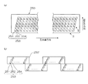
図2(a)は、インクジェットヘッド250の構造例を示す平面透視図であり、図2(b)は、インクジェットヘッド250の他の構造例を示す平面透視図である。図3は、インク室ユニットの立体的構成を示す断面図(図2(a)中、III−III線に沿う断面図)である。
FIG. 2A is a plan perspective view showing a structural example of the
記録紙面上に形成されるドットピッチを高密度化するためには、インクジェットヘッド250におけるノズルピッチを高密度化する必要がある。本例のインクジェットヘッド250は、図2(a)に示すように、インク滴の吐出孔であるノズル251と、各ノズル251に対応する圧力室252などからなる複数のインク室ユニット253を千鳥でマトリクス状に(2次元的に)配置させた構造を有し、これにより、ヘッド長手方向(紙搬送方向と直交する主走査方向)に沿って並ぶように投影される実質的なノズル間隔(投影ノズルピッチ)の高密度化を達成している。
In order to increase the dot pitch formed on the recording paper surface, it is necessary to increase the nozzle pitch in the
なお、図2(a)に図示したインク室ユニット253は、略正方形の平面形状を有する圧力室252の対角となる一方にノズル251が配置され、他方に供給口(供給絞り)が配置される。
In the
紙搬送方向と略直交する方向に記録媒体124の全幅に対応する長さにわたり一列以上のノズル列を構成する形態は本例に限定されない。例えば、図2(a)の構成に代えて、図2(b)に示すように、複数のノズル251が2次元に配列された短尺のヘッドブロック(ヘッドチップ)250’を千鳥状に配列して繋ぎ合わせることで記録媒体124の全幅に対応する長さのノズル列を有するラインヘッドを構成してもよい。また、図示は省略するが、短尺のヘッドを一列に並べてラインヘッドを構成してもよい。
The form in which one or more nozzle rows are configured over a length corresponding to the entire width of the
図3に示すように、各ノズル251は、インクジェットヘッド250のインク吐出面250aを構成するノズルプレート260に形成されている。ノズルプレート260は、例えば、Si、SiO2、SiN、石英ガラスのようなシリコン系材料、Al、Fe、Ni、Cuまたはこれらを含む合金のような金属系材料、アルミナ、酸化鉄のような酸化物材料、カーボンブラック、グラファイトのような炭素系材料、ポリイミドのような樹脂系材料で構成されている。
As shown in FIG. 3, each
ノズルプレート260の表面(インク吐出側の面)には、インクに対して撥液性を有する撥水膜262が形成されており、インクの付着防止が図られている。
A
各ノズル251に対応して設けられている圧力室252は、その平面形状が概略正方形となっており、対角線上の両隅部にノズル251と供給口254が設けられている。各圧力室252は供給口254を介して共通流路255と連通されている。共通流路255はインク供給源たるインク供給タンク(不図示)と連通しており、該インク供給タンクから供給されるインクは共通流路255を介して各圧力室252に分配供給される。
The
圧力室252の天面を構成し共通電極と兼用される振動板256には個別電極257を備えた圧電素子258が接合されており、個別電極257に駆動電圧を印加することによって圧電素子258が変形してノズル251からインクが吐出される。インクが吐出されると、共通流路255から供給口254を通って新しいインクが圧力室252に供給される。
A
なお、ノズルの配置構造は図示の例に限定されず、副走査方向に一列のノズル列を有する配置構造など、様々なノズル配置構造を適用できる。 The nozzle arrangement structure is not limited to the illustrated example, and various nozzle arrangement structures such as an arrangement structure having one nozzle row in the sub-scanning direction can be applied.
また、ライン型ヘッドによる印字方式に限定されず、記録媒体124の幅方向(主走査方向)の長さに満たない短尺のヘッドを記録媒体124の幅方向に走査させて当該幅方向の印字を行ない、1回の幅方向の印字が終わると記録媒体124を幅方向と直交する方向(副走査方向)に所定量だけ移動させて、次の印字領域の記録媒体124の幅方向の印字を行ない、この動作を繰り返して記録媒体124の印字領域の全面にわたって印字を行なうシリアル方式を適用してもよい。
Further, the printing method is not limited to a line type head, and printing in the width direction is performed by scanning a short head less than the length of the
(メンテナンス部の説明)
図4は、図1に示すインクジェット記録装置の画像記録位置とメンテナンス位置との関係を模式的に示す説明図であり、図5は、描画部116に隣接して設けられるメンテナンス処理部300の概略構成を示す斜視図である。なお、図5においては、洗浄装置310の外観をわかりやすくするため、インクジェットヘッド172を実際の位置より離して記載しているが、実際には、メンテナンス位置においてインクジェットヘッド172と洗浄装置310は近接して配置されている。
(Description of the maintenance department)
4 is an explanatory diagram schematically showing the relationship between the image recording position and the maintenance position of the ink jet recording apparatus shown in FIG. 1, and FIG. 5 is an outline of the
なお、図4では、便宜上、インクジェットヘッド172Yのみが図示されており、図5では、インクジェットヘッド172M,172K,172C,172Yをまとめて符号172を付して図示されている。また、図示の都合上、図5ではインクジェットヘッド172の長手方向について縮小されている。
In FIG. 4, only the
描画部116において、各インクジェットヘッド172M,172K,172C,172Yは、図4に示すように、ヘッド支持フレーム40に取り付けられて、描画ドラム170の周囲に配置される。
In the
図4に示すように、インクジェットヘッド172M,172K,172C,172Yを支持するヘッド支持フレーム40は、描画ドラム170の回転軸18と直交して設けられた一対のサイドプレート42L,42Rと、その一対のサイドプレート42L,42Rを上端部で連結する連結フレーム44とで構成されている。
As shown in FIG. 4, the
一対のサイドプレート42L,42Rは、板状に形成されており、描画ドラム170を挟んで互いに対向するように配置されている。この一対のサイドプレート42L、42Rの内側には、各インクジェットヘッド172M,172K,172C,172Yを取り付けるための取付部46Y,46C,46K,46Mが設けられている(図4では、便宜上、取付部46Yのみ図示)。
The pair of
取付部46Y,46C,46K,46Mは、描画ドラム170の回転軸18を中心とした同心円上に一定の間隔をもって放射状に配置されている。各インクジェットヘッド172M,172K,172C,172Yは、その両端に形成された被取付部48Y,48C,48K,48M(図4では、便宜上、被取付部48Yのみ図示)を取付部46Y,46C,46K,46Mに固定することにより、ヘッド支持フレーム40に取り付けられる。
The
そして、このヘッド支持フレーム40に取り付けられることにより、各インクジェットヘッド172M,172K,172C,172Yが、描画ドラム170の回転軸18を中心とした同心円上に一定の間隔をもって放射状に配置される。
Then, by attaching to the
ヘッド支持フレーム40は、図示しないガイドレールにガイドされて、描画ドラム170の回転軸18と平行にスライド移動自在に設けられている。そして、図示しないリニア駆動機構(たとえば、送りネジ機構など)に駆動されて、図4に実線で示す「画像記録位置」と図4に破線で示す「メンテナンス位置」との間を移動する。
The
各インクジェットヘッド172M,172K,172C,172Yは、ヘッド支持フレーム40を画像記録位置に位置させると、描画ドラム170の周囲に配置され、画像記録可能な状態になる。
The ink jet heads 172M, 172K, 172C, and 172Y are arranged around the drawing
メンテナンス位置は、各インクジェットヘッド172M,172K,172C,172Yが描画ドラム170から退避する位置に設定される。このメンテナンス位置には、各インクジェットヘッド172M,172K,172C,172Yの吐出面(図3に図示したインク吐出面250a、図6に符号172Aを付して図示)の洗浄、保湿を行なうための洗浄装置310(310Y)が設けられる。
The maintenance position is set to a position where each
洗浄装置310は、インクジェットヘッド172M,172K,172C,172Yのそれぞれに対応する洗浄部310M,310K,310C,310Yを含んで構成される。図4では、インクジェットヘッド172Yに対応する洗浄部310Yのみが図示されている。
The
なお、洗浄部310M,310K,310C,310Yの基本的な構成は共通しているので、以下の説明では、洗浄部310M,310K,310C,310Yをまとめて洗浄装置310として説明する。
Since the basic configurations of the
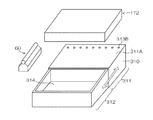
図5に示す洗浄装置310は、インクジェットヘッド172(インクジェットヘッド172M,172K,172C,172Y)の吐出面を洗浄する洗浄液膜保持部311と、吐出面172Aを覆うキャップ部(保湿手段)312とから構成されている。
The
図5に示すように、洗浄液膜保持部311は洗浄液の液膜が形成される洗浄液膜保持面311Aを有している。洗浄液膜保持面311Aは、吐出面172A(図6参照)に対応する傾斜面であり、洗浄液を供給するための洗浄液供給路313A(図6参照)及び洗浄液供給口313Bが設けられている。図5に示す洗浄液膜保持面311Aは、傾斜上側の端部近傍に、傾斜方向と直交する方向に沿って複数の洗浄液供給口313Bが等間隔に並べられている。
As shown in FIG. 5, the cleaning liquid
なお、洗浄液供給路313A及び洗浄液供給口313Bを含む洗浄液供給口部に代わり、洗浄液膜保持面311に対向する側から洗浄液を供給する態様も可能である。また、洗浄液膜保持面311Aの幅(インクジェットヘッド172の長手方向と平行方向の長さ)は、インクジェットヘッド172の長手方向と平行方向の長さに対応しており、ノズル(図2参照)配設されるノズル配設領域の同方向における長さ以上となっている。
In addition, instead of the cleaning liquid supply port portion including the cleaning
キャップ部312は、洗浄液膜保持面311Aの傾斜下側に配置され、洗浄液膜保持面311Aを流れ落ちた洗浄液が収容される洗浄液貯留槽314を具備している。洗浄液貯留槽314に洗浄液を蓄えた状態で洗浄液貯留槽314の開口を吐出面172Aに近接させることで、吐出面172Aが保湿される。
The
洗浄装置310は、メンテナンス位置(図4参照)に位置するインクジェットヘッドの短手方向に沿って移動可能に構成されている。洗浄液膜保持面311Aを吐出面172Aに近接させると吐出面172Aの洗浄が実行され、洗浄液貯留槽314を吐出面172Aに近接させると吐出面172Aの保湿が実行される。なお、吐出面の洗浄及び保湿の詳細は後述する。
The
図4に戻り、画像記録位置とメンテナンス位置との間には、各インクジェットヘッド172M,172K,172C,172Yの吐出面172AM,172AK,172AC,172AYを清掃するための吐出面清掃装置(吐出面払拭装置)60が設けられている。各インクジェットヘッド172M,172K,172C,172Yは、メンテナンス位置から画像記録位置に移動する過程で、または、画像記録位置からメンテナンス位置に移動する過程で、この吐出面清掃装置60によって吐出面172A(172AM,172AK,172AC,172AY)が清掃(払拭)される。
Returning to FIG. 4, between the image recording position and the maintenance position, a discharge surface cleaning device (discharge surface wiping) for cleaning the discharge surfaces 172AM, 172AK, 172AC, 172AY of the inkjet heads 172M, 172K, 172C, 172Y. Device) 60 is provided. Each of the inkjet heads 172M, 172K, 172C, and 172Y is ejected
図4に示す態様では、ウエブにより吐出面172Aを払拭する態様が図示されているが、ウエブに代わりワイパーブレードを備える形態も可能である。
In the mode shown in FIG. 4, a mode in which the
以下、洗浄装置310の構成について説明する。
Hereinafter, the configuration of the
図6は、洗浄装置310の概略構成図であり、図6(a)は、吐出面172Aを洗浄する洗浄モードにおけるインクジェットヘッド172と洗浄装置310の配置を示し、図6(b)は、吐出面172Aを保湿する保湿モードにおけるインクジェットヘッド172と洗浄装置310の配置を示す。
FIG. 6 is a schematic configuration diagram of the
図6は、フルライン型のインクジェットヘッド172の幅方向(副走査方向)から見た図であり、同図における紙面を貫く方向はヘッド172の長手方向(副走査方向と直交する主走査方向)である。
FIG. 6 is a diagram viewed from the width direction (sub-scanning direction) of the full-line type
洗浄装置310の傾斜の上流側(上部側)には、洗浄液膜保持部311が設けられる。洗浄液膜保持部311はインクジェットヘッド172の吐出面172Aに塗布する洗浄液が保持される洗浄液膜保持面311Aを有している。該洗浄液膜保持面311Aに洗浄液を供給する洗浄液供給口313Bが洗浄液膜保持面311Aの傾斜の上部311Bにおける端部近傍に設けられる。
A cleaning liquid
また、洗浄装置310の傾斜の下流側(下部側)にはキャップ部312が設けられる。洗浄液膜保持部311は、洗浄液供給路313A及び洗浄液供給口313Bを介して供給される洗浄液を貯留する洗浄液タンク324と、洗浄液膜保持面311Aへの洗浄液の供給量(単位時間あたりの洗浄液供給量)を制御するポンプ325と、を具備している。
Further, a
インクジェットヘッド172の吐出面172Aと洗浄液膜保持面311Aの間に、洗浄液供給口313Bから流し込まれたわずかな量の洗浄液は、吐出面172Aの撥液性を利用して濡れ広がるとともに、吐出面172Aと洗浄液膜保持面311Aとの間にメニスカスを形成しながら上部311Bから下部に向かって滑り落ちる。
A slight amount of the cleaning liquid poured from the cleaning
洗浄液膜保持面311Aを滑り落ちた洗浄液は、洗浄液膜保持面311Aの傾斜の下部のキャップ部312の洗浄液貯留槽314に落下する。洗浄液貯留槽314に集められた洗浄液は、インクジェットヘッド172の吐出面172Aの保湿に用いられる。
The cleaning liquid that has slipped down the cleaning liquid
洗浄液が、吐出面172Aと洗浄液膜保持面311Aとの間にメニスカスを形成しながら滑り落ちるためには、吐出面の表面性(接触角)、洗浄液保持面の表面性(接触角)、洗浄液の物性(粘度)、洗浄液の流速(単位時間あたりの供給量)、洗浄液供給口の形状、サイズ、を適宜最適化する必要がある。
In order for the cleaning liquid to slide down while forming a meniscus between the
洗浄液膜保持部311でインクジェットヘッド172の吐出面172Aの洗浄が行われた後、洗浄装置310は吐出面172Aと平行方向に沿って上部に向かって(図6において右側に)スライドし、吐出面172Aがキャップ部312の下になるように(吐出面172Aがキャップ部312に近接するように)移動する。
After the
洗浄装置310は、図示しないガイドレールにガイドされて、吐出面172Aに沿ってスライド移動自在に設けられている。そして、図示しないリニア駆動機構(たとえば、送りネジ機構など)に駆動されて、吐出面172Aに対向する位置に、洗浄液膜保持部311またはキャップ部312がくるように、スライド移動する。
The
これにより、洗浄モードと保湿モードの選択が可能となる。キャップ部312の洗浄液貯留槽314には、洗浄液膜保持面311Aから滑り落ちてきた洗浄液が蓄えられており、この洗浄液貯留槽314に蓄えられた洗浄液によりキャップ部312を高湿度に維持することができるので、インクジェットヘッド172の吐出面172Aを保湿することができる。
As a result, the cleaning mode and the moisture retention mode can be selected. The cleaning
なお、図6では、洗浄装置310をスライド移動させる態様で説明したが、インクジェットヘッド172を移動させることで、吐出面172Aをキャップ部312の上部にくるように移動させることができる。また、洗浄装置310とインクジェットヘッド172の両方を移動させることで、吐出面172Aと、洗浄液膜保持部311およびキャップ部312との位置を調節することもできる。
In FIG. 6, the
洗浄装置310の洗浄液膜保持面311Aとインクジェットヘッド172の吐出面172AとのクリアランスH1は、0mmより大きく2mm以下とすることが好ましく、より好ましくは、0.1mm以上0.5mm以下とすることが好ましい。クリアランスH1を上記範囲とすることで、洗浄液が、洗浄液膜保持面311Aと吐出面172Aとの間を濡れ拡がりながら移動させることができる。
Clearance H 1 between the
また、洗浄装置310をスライドさせ、インクジェットヘッド172の吐出面172Aが、キャップ部312の上部にある場合、キャップ部312の洗浄液貯留槽314の上部と吐出面172AとのクリアランスH2は、できるだけ短くすることが好ましい。
Further, the
クリアランスH2を短くすることで、洗浄液貯留槽314に蓄えられた洗浄液が揮発し、洗浄液貯留槽314内を高湿度に維持することができる。クリアランスH2は、0mmより大きく2mm以下とすることが好ましく、より好ましくは、0.5mmより大きく1.5mm以下とすることが好ましい。
By shortening the clearance H 2, can be cleaning liquid stored in the cleaning
また、洗浄液貯留槽314の開口部は、インクジェットヘッド172の吐出面172Aの面積と同じ、あるいは、それ以上であることが好ましい。洗浄液貯留槽314の開口部を吐出面172Aの面積以上とすることで、吐出面172A全面を効率良く保湿することができる。
The opening of the cleaning
図5、6においては、洗浄装置310は、洗浄液膜保持部311とキャップ部312が一体となった洗浄装置310を用いているが、洗浄液膜保持部311とキャップ部312を別々の構成として連続配置させた洗浄装置を用いることも可能である。洗浄液膜保持部311とキャップ部312を別々の構成としても、これら2つの構成を連続配置させ、同時にスライドさせることで、洗浄モードと保湿モードの選択を容易にするという効果を得ることができる。
5 and 6, the
しかしながら、洗浄液膜保持部311とキャップ部312が一体となった洗浄装置310を用いることで、装置を大幅に小型化することができ、また、洗浄モードで使用した洗浄液を保湿モードで再利用することができる。
However, by using the
また、キャップ部312の洗浄液貯留槽314の周囲にシール部(図示せず)を設けることも可能である。シール部を設け、シール部をインクジェットヘッド172の吐出面172Aに接触させることで、洗浄液貯留槽314内の湿度をより高湿度に維持することができるので、吐出面172Aの保湿性能を向上させることができる。
In addition, a seal portion (not shown) can be provided around the cleaning
したがって、ノズル内のインクの乾燥を効率よく防止することができるとともに、洗浄液膜保持部311で洗浄に用いられた洗浄液のパージ、または、インクのパージを洗浄液貯留槽314で行なうこともできる。シール部を設けることで、パージを洗浄液貯留槽314で行なっても、周囲に飛び散ることを防止することができる。なお、シール部は、洗浄装置310の傾斜の上流側からは洗浄液が流れてくるので、洗浄液貯留槽314の下流および側部の周囲に設けることが好ましい。
Accordingly, it is possible to efficiently prevent the ink in the nozzles from being dried, and it is also possible to purge the cleaning liquid used for cleaning in the cleaning liquid
なお、図5においては、洗浄液膜保持部311とキャップ部312との間に段差が設けられているが、これは、洗浄装置310が洗浄液膜保持部311とキャップ部312とを別々に作成しているからである。すなわち、洗浄液膜保持面311Aとキャップ部312の開口面とは連続面でもよいし、段差を介してつなげられた構造でもよい。
In FIG. 5, a step is provided between the cleaning liquid
この段差は小さくすることが好ましいが、洗浄液膜保持部311とキャップ部312を別々に製造した場合、製造時の誤差により、キャップ部312が高くなってしまうと洗浄液が洗浄液膜保持部311からキャップ部312に流れにくくなるため、キャップ部312の開口面は、洗浄液膜保持部311より低く製造することが好ましい。
It is preferable to reduce this step, but when the cleaning liquid
(制御系の説明)
図7は、インクジェット記録装置100のシステム構成を示す要部ブロック図である。インクジェット記録装置100は、通信インターフェース270、システムコントローラ272、メモリ274、モータドライバ276、ヒータドライバ278、プリント制御部280、画像バッファメモリ282、ヘッドドライバ284等を備えている。
(Description of control system)
FIG. 7 is a principal block diagram showing the system configuration of the
通信インターフェース270は、ホストコンピュータ286から送られてくる画像データを受信するインターフェース部である。通信インターフェース270にはUSB(Universal Serial Bus)、IEEE1394、イーサネット(登録商標)、無線ネットワークなどのシリアルインターフェースやセントロニクスなどのパラレルインターフェースを適用することができる。この部分には、通信を高速化するためのバッファメモリ(不図示)を搭載してもよい。ホストコンピュータ286から送出された画像データは通信インターフェース270を介してインクジェット記録装置100に取り込まれ、一旦メモリ274に記憶される。
The
メモリ274は、通信インターフェース270を介して入力された画像を一旦格納する記憶手段であり、システムコントローラ272を通じてデータの読み書きが行われる。メモリ274は、半導体素子からなるメモリに限らず、ハードディスクなど磁気媒体を用いてもよい。
The
システムコントローラ272は、中央演算処理装置(CPU)およびその周辺回路等から構成され、所定のプログラムに従ってインクジェット記録装置100の全体を制御する制御装置として機能するとともに、各種演算を行なう演算装置として機能する。即ち、システムコントローラ272は、通信インターフェース270、メモリ274、モータドライバ276、ヒータドライバ278、処理液付与制御部296、乾燥制御部297、定着制御部298等の各部を制御し、ホストコンピュータ286との間の通信制御、メモリ274の読み書き制御等を行なうとともに、上記の各部を制御する制御信号を生成する。
The
メモリ274には、システムコントローラ272のCPUが実行するプログラムおよび制御に必要な各種データなどが格納されている。なお、メモリ274は、書換不能な記憶手段であってもよいし、EEPROMのような書換可能な記憶手段であってもよい。メモリ274は、画像データの一時記憶領域として利用されるとともに、プログラムの展開領域およびCPUの演算作業領域としても利用される。
The
プログラム格納部290には各種制御プログラムが格納されており、システムコントローラ272の指令に応じて、制御プログラムが読み出され、実行される。プログラム格納部290はROMやEEPROMなどの半導体メモリを用いてもよいし、磁気ディスクなどを用いてもよい。外部インターフェースを備え、メモリカードやPCカードを用いてもよい。もちろん、これらの記録媒体のうち、複数の記録媒体を備えてもよい。なお、プログラム格納部290は動作パラメータ等の記録手段(不図示)と兼用してもよい。
Various control programs are stored in the
モータドライバ276は、システムコントローラ272からの指示に従ってモータ288を駆動するドライバである。図7には、装置内の各部に配置されるモータを代表して符号288で図示されている。例えば、図7に示すモータ288には、図1に示す給紙胴152、処理液ドラム154、描画ドラム170、乾燥ドラム176、定着ドラム184、渡し胴194などの回転を駆動するモータ、第1〜第3中間搬送部126、128、130の中間搬送体の回転を駆動するモータ、インクジェットヘッド172M,172K,172C,172Yを画像記録位置とメンテナンス位置との間を移動させる機構に具備されるモータ、洗浄装置310を移動させる機構のモータなどが含まれている。
The
ヒータドライバ278は、システムコントローラ272からの指示に従って、ヒータ289を駆動するドライバである。図7には、装置内の各部に配置されるヒータを代表して符号289で図示されている。例えば、図7に示すヒータ289には、図1に示す乾燥部118に設けられる溶媒乾燥装置178のハロゲンヒータ182などが含まれている。さらに、図1に示す乾燥ドラム176、定着ドラム184の表面を加熱するヒータも含まれている。
The
さらに、このインクジェット記録装置100は、処理液付与制御部296、乾燥制御部297、および定着制御部298を備えており、システムコントローラ272からの指示に従って、それぞれ、処理液塗布装置156、溶媒乾燥装置178、および定着ローラ188などの各部の動作を制御する。
Furthermore, the
プリント制御部280は、システムコントローラ272の制御に従い、メモリ274内の画像データから印字制御用の信号を生成するための各種加工、補正などの処理を行なう信号処理機能を有し、生成した印字データ(ドットデータ)をヘッドドライバ284に供給する制御部である。プリント制御部280において所要の信号処理が施され、該画像データに基づいて、ヘッドドライバ284を介してヘッド172の吐出液滴量(打滴量)や吐出タイミングの制御が行われる。これにより、所望のドットサイズやドット配置が実現される。
The
また、プリント制御部280には画像バッファメモリ282が備えられており、プリント制御部280における画像データ処理時に画像データやパラメータなどのデータが画像バッファメモリ282に一時的に格納される。また、プリント制御部280とシステムコントローラ272とを統合して1つのプロセッサで構成する態様も可能である。
The
ヘッドドライバ284は、プリント制御部280から与えられる画像データに基づいてインクジェットヘッド172の圧電素子に印加される駆動信号を生成するとともに、該駆動信号を圧電素子に印加して圧電素子を駆動する駆動回路を含んで構成される。なお、図7に示すヘッドドライバ284には、インクジェットヘッド172の駆動条件を一定に保つためのフィードバック制御系を含んでいてもよい。
The
センサ285は、装置内の各部に設けられる各種センサ類であり、図1に示したインラインセンサ190の他、温度センサ、位置検出センサ、圧力センサ等が含まれている。センサ285の出力信号はシステムコントローラ272に送られ、システムコントローラ272は該出力信号に基づいて装置各部に対して制御信号を送り、装置各部の制御が行われている。
The
メンテナンス制御部279は、システムコントローラ272から送られた制御信号に基づいて、図4〜図6に図示した洗浄装置310を含むメンテナンス処理部300(図4参照)の制御を行なうブロック図である。また、メンテナンス制御部279はノズル内の劣化したインクをインクジェットヘッド172の外部に排出する予備吐出、吸引等のメンテナンス処理を実行に関する制御信号を各部に送出する機能を備えている。
The
メンテナンス制御部279の詳細な構成の図示は省略するが、メンテナンス制御部279は、システムコントローラ272の制御信号に基づいて、インクジェットヘッド172の移動タイミングや移動速度を制御するとともに、洗浄装置310をスライドさせるタイミング、ポンプ325の回転速度(洗浄液の流速)、吐出面清掃装置60のウエブの搬送駆動、ウエブの上下機構などの動作を制御する。
Although the detailed configuration of the
(洗浄モードの説明)
次に、インクジェットヘッド172(吐出面172A)を洗浄する洗浄モードについて説明する。図8は、洗浄モードの制御の流れを示すフローチャートである。メンテナンス制御部279は、以下の手順によりインクジェットヘッド172のメンテナンス(吐出面172Aの洗浄処理)が実行されるようにメンテナンス処理部300を制御する。
(Description of cleaning mode)
Next, a cleaning mode for cleaning the inkjet head 172 (
先ず、インクジェットヘッド172をメンテナンス処理部300の処理領域に移動させる(ステップS12)。次に、洗浄装置310を上下方向に移動させて、洗浄液膜保持面311A(図6参照)と吐出面172AとのクリアランスH1を調整する(ステップS14)。
First, the
インクジェットヘッド172と洗浄装置310との位置が決められると、洗浄液供給口313Bから洗浄液膜保持面311Aに洗浄液が供給される(ステップS16)。洗浄液供給口313Bから洗浄液膜保持面311Aへ供給される単位時間あたりの洗浄液量は、ポンプ325の回転速度および動作時間を制御することで調整可能である。
When the positions of the
洗浄液の供給開始から所定時間が経過すると、吐出面172Aと洗浄液膜保持面311Aとの間の洗浄液が全体に濡れ広がる。すなわち、ステップS18において洗浄液が全体に濡れ広がるまで、洗浄液の供給開始からの経過時間が監視される(ステップS18のNo判定)。洗浄液の供給開始から洗浄液が全体に濡れ広がるまでの時間が経過すると(ステップS18のYes判定)、洗浄液の供給が停止される(ステップS20)。
When a predetermined time has elapsed from the start of the supply of the cleaning liquid, the cleaning liquid between the
洗浄液が吐出面172Aの全面に塗布されてから所定の時間(吐出面172Aの汚れが洗浄液に溶解するまでの時間)が経過した後に、インクジェットヘッド172をメンテナンス位置から画像記録位置に移動させる際に(ステップS22)、吐出面172Aが吐出面清掃装置60のウエブに接触して、吐出面172Aの洗浄液が拭き取られる。
When the
(保湿モードの説明)
次に、インクジェットヘッド172の保湿モードについて説明する。図9は、保湿モードの制御の流れを示すフローチャートである。まず、インクジェットヘッド172を画像記録位置からメンテナンス位置に移動させる。なお、洗浄液の拭き取りは画像記録位置からメンテナンス位置に移動させるこの時点で行なうことも可能である。
(Description of moisturizing mode)
Next, the moisture retention mode of the
洗浄装置310は、インクジェットヘッド172の吐出面172Aの洗浄が終わった後、吐出面172Aの水平面の下に洗浄装置310のキャップ部312がくるように、洗浄装置310をスライドさせる(ステップS102)。
After the cleaning of the
インクジェットヘッド172をメンテナンス位置に移動させ、吐出面172Aの真下に洗浄装置310のキャップ部312を移動させると、吐出面172Aとキャップ部312とのクリアランスが調整され(ステップS204)、吐出面172Aの保湿が行われ、次の画像形成(画像記録)に備える(ステップS106)。
When the
ステップS106において、次の画像がないと判断されると(No判定)、吐出面の保湿が継続される。一方、ステップS106において、次の画像があると判断されると(Yes判定)、洗浄装置310をスライドさせ(ステップS108)、インクジェットヘッド172を画像記録位置に移動させる(ステップS110)。
If it is determined in step S106 that there is no next image (No determination), the moisture retention on the ejection surface is continued. On the other hand, if it is determined in step S106 that there is a next image (Yes determination), the
このようにして、画像記録間のインターバルや、画像記録終了後には、保湿モードが実行され、インクジェットヘッド172の吐出面172Aの乾燥が防止される。
In this way, the interval between image recording and after the end of image recording, the moisture retention mode is executed, and drying of the
上記の如く構成されたメンテナンス処理部300によれば、吐出面172Aと略平行に傾けられて配置された洗浄液膜保持面311Aと吐出面172Aとの間に、傾斜の上部311Bに設けられた洗浄液供給口313Bから洗浄液を供給すると、吐出面172Aと洗浄液膜保持面311Aとの間において洗浄液が濡れ広がるとともに傾斜の上部から下部へ移動するので、非接触で吐出面172Aに洗浄液を塗布することができ、洗浄液の消費量が大幅に削減される。
According to the
また、洗浄液膜保持部311に連続してキャップ部312が配置され、キャップ部312に設けられた洗浄液貯留槽314に吐出面172Aの洗浄に使用した洗浄液を蓄えて、吐出面172Aを保湿することができるので、吐出面172Aのインクの乾燥を防止することができ、洗浄液の使用量を大幅に低減することが可能となる。
In addition, the
また、洗浄モードを行なう洗浄液膜保持部311とキャップ部312を一体型の洗浄装置310とすることで、装置の小型化をすることができる。
Further, the cleaning liquid
なお、図1に示すインクジェット記録装置100は、インクジェットヘッド172Y,172Mとインクジェットヘッド172C,172Kとは吐出面の傾斜角度が異なっている。このような場合には、インクジェットヘッド172Y,172Mに対応する洗浄液膜保持面311Aを有する洗浄装置310と、インクジェットヘッド172C,172Kに対応する洗浄液膜保持面311Aを有する洗浄装置310とを、別々に備えることが好ましい。
In the ink
また、インクジェットヘッド172M,172K,172C,172Yのそれぞれについて、別々に洗浄装置310を備えることも可能である。
Moreover, it is also possible to provide the washing | cleaning
〔第2実施形態〕
(メンテナンス処理部の構成)
次に、本発明の第2実施形態に係るインクジェット記録装置におけるメンテナンス処理部300’について説明する。なお、第2実施形態に係るインクジェット記録装置の全体構成は図1に図示した構成を適用することができるので説明を省略する。また、以下の説明では、先に説明した第1実施形態と同一又は類似する部分には同一の符号を付し、その説明は省略する。
[Second Embodiment]
(Configuration of maintenance processing unit)
Next, the
図10は、第2実施形態に係るインクジェット記録装置における画像記録位置とメンテナンス位置との関係を模式的に示す説明図であり、図4に対応している。図10に示す態様では、図4に図示した吐出面清掃装置60が省略され、洗浄装置310’(310Y’)のキャップ部(図10中不図示、図11に符号312’を付して図示)の内部にワイパーブレード(図10中不図示、図11に符号360を付して図示)が設けられている。
FIG. 10 is an explanatory diagram schematically showing the relationship between the image recording position and the maintenance position in the ink jet recording apparatus according to the second embodiment, and corresponds to FIG. In the embodiment shown in FIG. 10, the discharge
図11は、図10に示す洗浄装置310’(310Y’)の概略構成を示す斜視図である。図示の都合上、図11では図6(a),(b)に図示した洗浄液タンク324及びポンプ325の図示は省略され、インクジェットヘッド172の長手方向について縮小されている。
FIG. 11 is a perspective view illustrating a schematic configuration of the
図11に示すように、洗浄装置310’は、キャップ部312’(洗浄液貯留槽314)にワイパーブレード360を備えている。ワイパーブレード360は、厚さが1ミリメートル程度の弾性部材により構成されている。
As shown in FIG. 11, the
ワイパーブレード360に適用される材料として、NBR(ニトリルゴム)、シリコンゴム、EPDM(エチレン‐プロピレン‐ジエンゴム)などのゴム部材や、スチレン系、オレフィン系、ポリエステル系などの熱可撓性エストラマー等の弾性体が挙げられる。
The materials applied to the
洗浄液の作用によって、吐出面172Aに付着したインクが洗浄液に溶解して吐出面172Aから除去されるので、ワイパーブレード360は、吐出面172Aに付着した洗浄液を払うことができればよく、極めて薄いものでよい。また、ワイパーブレード360の吐出面172Aに対する当接圧も、ワイパーブレード360が吐出面172Aに接触する程度の極めて弱いものでよい。
By the action of the cleaning liquid, the ink attached to the
さらに、ワイパーブレード360の吐出面172Aとの接触面積をより大きくすることで、より払拭効果を高めることができる。
Furthermore, the wiping effect can be further enhanced by increasing the contact area of the
図11に示す態様では、ワイパーブレード360は、キャップ部312’(洗浄液貯留槽314)の洗浄液の流れ方向における最上流側(最上部、洗浄装置310’の移動方向における最下流側、洗浄液貯留槽314の洗浄液膜保持面311A側の端部)に配置される。
In the embodiment shown in FIG. 11, the
ワイパーブレード360のインクジェットヘッド172の長手方向の長さは、インクジェットヘッド172の同方向の全長に対応しており、少なくとも、ノズルが配設されるノズル配設領域の同方向の長さ以上となっている。
The length of the
また、ワイパーブレード360は、洗浄液貯留槽314の内部に配置されるワイパーブレード支持部材362によって、ワイパーブレード支持部材362を回転軸として回転可能に支持されている。
Further, the
なお、ワイパーブレード支持部材362を覆うカバーを備えることで、ワイパーブレード支持部材362と洗浄液との接触を避けることでき、ワイパーブレード支持部材362の洗浄液による腐食が防止される。
By providing the cover that covers the wiper
図12は、図11に示すワイパーブレードの支持構造を示す平面図である。同図に示すように、ワイパーブレード360のインクジェットヘッド172の吐出面172Aに接触させる部分の反対側は、ワイパーブレード支持部材362により支持されている。ワイパーブレード支持部材362は、カップリング364を介してモータ366の回転軸に連結され、モータ366の回転軸を回転させることで、ワイパーブレード支持部材362を回転させることができ、ワイパーブレード360の位置(向き)を変更することができる。
12 is a plan view showing the support structure of the wiper blade shown in FIG. As shown in the figure, the
すなわち、ワイパーブレード360は、図12に実線により図示された位置(向き)と破線により図示された位置(向き)との間の位置(向き)を選択的に切り換えることが可能である。例えば、モータ366にステッピングモータを適用すると、パルス信号によりワイパーブレード360の位置(向き)を容易に変更することができる。
That is, the
図13は、ワイパーブレード360の構造例を示す説明図である。図13(a)に示すように、インクジェットヘッド172の長手方向の全幅に対応する長尺のワイパーブレードを適用してもよいし、図13(b)に示すように、インクジェットヘッド172の長手方向の全幅よりも短い短尺のワイパーブレード360A,360B,360Cを組み合わせて、インクジェットヘッド172の長手方向の全幅に対応してもよい。
FIG. 13 is an explanatory view showing a structural example of the
図13(b)には、短尺のワイパーブレード360A,360B,360Cを千鳥配置した態様を例示したが、さらに多数の短尺のワイパーブレードを備える形態も可能である。
FIG. 13B illustrates a mode in which
(ワイプモードの説明)
図14(a)から(c)は、本例に示す洗浄装置310’のワイプモードを模式的に示す説明図である。なお、図14では、図6(a),(b)に図示した洗浄液タンク324及びポンプ325の図示は省略されている。図14(a)は、洗浄モードが実行されている状態を示している。これは、先に説明した第1実施形態と同一であり、説明は省略する。
(Explanation of wipe mode)
FIGS. 14A to 14C are explanatory views schematically showing the wipe mode of the
洗浄モードが終了すると、図14(b),(c)に示すワイプモードに移行する。ワイプモードでは、キャップ部312’の洗浄液の流れ方向における最上流側(洗浄装置310の移動方向における最下流側)に配置されたワイパーブレード360を吐出面172Aに接触させ、洗浄装置310’のスライド移動によって吐出面172Aが払拭される。
When the cleaning mode is completed, the mode is shifted to the wipe mode shown in FIGS. In the wipe mode, the
先に実行される洗浄モードにおいて吐出面172Aは十分に湿潤されているので、ワイパーブレード360による吐出面172Aの払拭処理では、洗浄液を供給する必要がない。ただし、ワイプモードに移行した後に洗浄液を連続供給して、メンテナンス条件としてより有利なウエットワイピングを行うことも可能である。
Since the
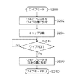
図15は、ワイプモードの制御の流れを示すフローチャートである。ワイプモードが開始されると(ステップS200)、ワイパーブレード360はワイプ位置(図14(a)に示す状態)に設定され(ステップS202)、洗浄装置310’(キャップ部312’)を吐出面172Aに沿ってスライド移動させる(ステップS204)。
FIG. 15 is a flowchart showing a flow of control in the wipe mode. When the wipe mode is started (step S200), the
次に、洗浄装置310’の移動時間(又は移動距離)がカウントされ、吐出面172Aの全面のワイピングが終了したか否かが判断される(ステップS206)。ステップS206において、吐出面172Aの全面のワイピングが終了していないと判断されると(No判定)、ワイピング処理(洗浄装置310’のスライド移動)が継続される。
Next, the movement time (or movement distance) of the
一方、ステップS206において、吐出面172Aの全面のワイピングが終了したと判断されると(Yes判定)、ワイパーブレード360が洗浄位置(図16参照)に設定され(ステップS208)、ワイプモードは終了される(ステップS210)。
On the other hand, when it is determined in step S206 that wiping of the
このように、吐出面172Aと洗浄装置310’とを相対移動させることで、洗浄モードからワイプモードへの切り換えがされ、さらに、ワイプモードが実行されるので、効率のよいメンテナンスが実現される。
As described above, the
(保湿モード(ワイパーブレード洗浄モード)の説明)
図16は、本例に示す洗浄装置310’の保湿モード(ワイパーブレード洗浄モード)を模式的に示す説明図である。先に説明したワイプモードが終了されると、保湿モードに移行する。保湿モードでは、吐出面172Aと対向する位置にキャップ部312’がセットされる。
(Description of moisturizing mode (wiper blade cleaning mode))
FIG. 16 is an explanatory view schematically showing a moisture retention mode (wiper blade cleaning mode) of the
保湿モードにおいて使用されるキャップ部312’内の洗浄液は、洗浄モードにおいて使用された洗浄液が洗浄液貯留槽314内に回収されたものが使用される。さらに、保湿モード中に、ワイパーブレード360の洗浄処理が施される。
As the cleaning liquid in the
すなわち、ワイパーブレード支持部材362を回転させて、少なくともワイパーブレード360の吐出面172Aに接触させる部分を洗浄液貯留槽314内の洗浄液に浸漬させる。そうすると、洗浄液の作用によってワイパーブレード360の吐出面172Aに接触させる部分に付着している汚れが除去される。
That is, the wiper
なお、図16に破線で図示したように、ワイパーブレード360の向きをワイプモードに対して180°変えて、ワイパーブレード360のより広い範囲を洗浄液に接触させるとよい。
As indicated by broken lines in FIG. 16, the
本発明の第2実施形態によれば、吐出面172Aの洗浄に用いた洗浄液を吐出面172Aの保湿に用いるとともに、ワイパーブレード360の洗浄にも用いることで、洗浄液が有効に活用されるとともに洗浄液の使用量の大幅な削減が見込まれる。
According to the second embodiment of the present invention, the cleaning liquid used for cleaning the
また、洗浄液膜保持部311とキャップ部312’との共通化とともに、キャップ部312’にワイパーブレード360を備えることで、吐出面の洗浄、吐出面の洗浄液の払拭、吐出面の保湿、ワイパーブレード360の洗浄を一連の動作で行うことができ、装置構成及び装置制御の簡略化、装置構成の小型化に寄与する。
In addition to the common use of the cleaning liquid
〔第3実施形態〕
(インクジェット記録装置の全体構成)
次に、本発明の第3実施形態について説明する。図17は、本発明の第3実施形態に係るインクジェット記録装置の概略構成を示す全体構成図である。同図に示すインクジェット記録装置400は、記録媒体402を水平搬送する記録媒体搬送部404を備えている。
[Third Embodiment]
(Overall configuration of inkjet recording apparatus)
Next, a third embodiment of the present invention will be described. FIG. 17 is an overall configuration diagram showing a schematic configuration of an ink jet recording apparatus according to the third embodiment of the present invention. The ink
すなわち、同図に示すインクジェット記録装置400は、記録媒体402を保持して搬送する記録媒体搬送部404と、記録媒体搬送部404に保持された記録媒体402に対して、M(マゼンタ)、K(黒)、C(シアン)、Y(イエロー)に対応するカラーインクを吐出させるインクジェットヘッド406M,406K,406C,406Yを含む印字部407と、を含んで構成されている。
That is, the ink
なお、図17に示すインクジェットヘッド406M,406K,406C,406Yは、図1に示すインクジェットヘッド172M,172K,172C,172Yと同一の構成が適用されるので、ここでは説明を省略する。 Note that the inkjet heads 406M, 406K, 406C, and 406Y shown in FIG. 17 have the same configuration as the inkjet heads 172M, 172K, 172C, and 172Y shown in FIG.
記録媒体搬送部404は、記録媒体402が保持される記録媒体保持領域に多数の吸着穴(不図示)が設けられた無端状の搬送ベルト408と、搬送ベルト408が巻き掛けられる搬送ローラ(駆動ローラ、従動ローラ)410,412と、記録媒体保持領域の搬送ベルト408の裏側(記録媒体402が保持される記録媒体保持面と反対側の面)に設けられ、記録媒体保持領域に設けられた不図示の吸着穴に負圧を発生させるチャンバー414と、チャンバー414に負圧を発生させる真空ポンプ416と、を含んでいる。
The recording
記録媒体402が搬入される搬入部418には、記録媒体402の浮きを防止するための押圧ローラ420が設けられるとともに、記録媒体402が排出される排出部422にもまた、押圧ローラ424が設けられている。
The
搬入部418から搬入された記録媒体402は、記録媒体保持領域に設けられた吸着穴から負圧が付与され、搬送ベルト408の記録媒体保持領域に保持される。
The
記録媒体402の搬送路上には、印字部407の前段側(記録媒体搬送方向上流側)に、記録媒体402の表面温度を所定範囲に調整するための温度調節部426が設けられるとともに、印字部407の後段側(記録媒体搬送方向下流側)に、記録媒体402上に記録された画像を読み取る読取装置(読取センサ)428が設けられている。
On the conveyance path of the
搬入部418から搬入された記録媒体402は、搬送ベルト408の記録媒体保持領域に吸着保持され、温度調節部426による温度調節処理が施された後に、印字部407において画像記録が行われる。
The
画像記録がされた記録媒体402は、読取装置428によって記録画像(テストパターン)が読み取られた後に、排出部422から排出される。
The
図17に図示は省略するが、インクジェット記録装置400は、メンテナンス処理部を備えている。メンテナンス処理部は、インクジェットヘッド406M,406K,406C,406Yを画像記録位置から記録媒体402の搬送方向と略直交する方向へ移動させたインクジェットヘッド406M,406K,406C,406Yのメンテナンス位置(退避位置)に配置される(図4参照)。
Although not shown in FIG. 17, the ink
インクジェットヘッド406M,406K,406C,406Yのメンテナンスモードが実行されると、インクジェットヘッド406M,406K,406C,406Yを画像記録位置からメンテナンス位置へ移動させる。メンテナンスモードが終了され、次の画像記録が実行される際に、インクジェットヘッド406M,406K,406C,406Yはメンテナンス位置から画像記録位置へ移動される。 When the maintenance mode of the inkjet heads 406M, 406K, 406C, and 406Y is executed, the inkjet heads 406M, 406K, 406C, and 406Y are moved from the image recording position to the maintenance position. When the maintenance mode is finished and the next image recording is executed, the inkjet heads 406M, 406K, 406C, 406Y are moved from the maintenance position to the image recording position.
(インクジェットヘッドのメンテナンスの説明)
図18(a)から(c)は、図17に示すインクジェット記録装置400における洗浄装置432の概略構成図であり、洗浄モードと保湿モードとの切り換えの説明図である。図18(a)から(c)に示す洗浄装置432は、図6に示す洗浄装置310と概略構造は共通しているが、洗浄液の液膜が保持される洗浄液膜保持面434が水平面と平行であり傾斜していない点が相違している。
(Inkjet head maintenance explanation)
18A to 18C are schematic configuration diagrams of the
すなわち、図18(a)から(c)に示す洗浄装置432は、洗浄液膜保持面434、洗浄液供給口436を有する洗浄液膜保持部437と、洗浄液膜保持面434の洗浄液が収容される洗浄液貯留槽440を有するキャップ部442とを含んで構成されている。
18A to 18C includes a cleaning liquid
なお、インクジェットヘッド406の吐出面406Aと洗浄液膜保持面434との間に洗浄液の液膜が形成されるメカニズムは先に説明した洗浄装置310と同じであるので、ここでは詳細な説明を省略する。
The mechanism for forming the cleaning liquid film between the
図18(a)に示すように、吐出面406Aと洗浄液膜保持面434との間に洗浄液による液膜438が形成されると、吐出面406Aに付着しているインク等の汚れは洗浄液膜438により溶解され、除去される。
As shown in FIG. 18A, when a
吐出面406Aと洗浄液膜保持面434との間に洗浄液膜438が形成されてから(洗浄液の供給が開始されてから)所定時間が経過すると、図18(b),(c)に示すように、洗浄装置432を吐出面406Aと略平行方向に移動させる。
When a predetermined time elapses after the cleaning
そうすると、図18(b)に示すように、吐出面406Aと洗浄液膜保持面434との間に形成された洗浄液膜438は、インクジェットヘッド406の移動に引きずられてインクジェットヘッド406とともに移動し、洗浄液貯留槽440の中に収容される。図18(b)では、洗浄液貯留槽440に収容された洗浄液は符号438’を付して図示されている。
Then, as shown in FIG. 18B, the cleaning
図18(c)は、吐出面406Aを保湿する保湿モードが実行されている状態が図示されている。インクジェットヘッド406の移動により洗浄液貯留槽440に収容された洗浄液438’は、保湿モードに利用される。
FIG. 18C illustrates a state in which a moisturizing mode for moisturizing the
洗浄液膜保持面434は、洗浄液供給口436の方へ洗浄液膜438が逆流しないように、水平面と平行であるか、吐出面406Aと接触しない程度に(図6に示したH1、H2の条件を満たすように)、洗浄液供給口436から洗浄液貯留槽440へ向かってわずかに下向きに傾斜している。
The cleaning liquid
以上説明したように、第3実施形態に係るインクジェット記録装置によれば、記録媒体402を水平面と平行に搬送する方式(インクジェットヘッド406の吐出面406Aが水平面と平行に配置される形態)においても、第1及び第2実施形態に係るインクジェット記録装置と同様の手法によりインクジェットヘッド406の吐出面406Aの洗浄及び保湿を行うことができ、同様の効果を得ることができる。
As described above, according to the ink jet recording apparatus according to the third embodiment, also in the method of transporting the
〔第4実施形態〕
次に、本発明の第4実施形態に係るインクジェット記録装置におけるインクジェットヘッドの洗浄装置について説明する。なお、以下に説明する第4実施形態では、インクジェット記録装置の全体構成は、図17に図示した第3実施形態と同一であるので、説明を省略する。また、以下の説明では、先に説明した部分と同一又は類似する部分には同一の符号を付し、その説明は省略する。
[Fourth Embodiment]
Next, an inkjet head cleaning device in an inkjet recording apparatus according to a fourth embodiment of the present invention will be described. In the fourth embodiment described below, the overall configuration of the ink jet recording apparatus is the same as that of the third embodiment illustrated in FIG. Moreover, in the following description, the same code | symbol is attached | subjected to the part which is the same or similar to the part demonstrated previously, and the description is abbreviate | omitted.
(洗浄モード、ワイプモードの説明)
図19(a)から(c)は、第4実施形態に係るインクジェット記録装置における洗浄装置432’の洗浄モード及びワイプモードを模式的に図示した説明図である。なお、図19(a)から(c)では、図6(a),(b)に図示した洗浄液タンク324及びポンプ325の図示は省略されている。
(Description of cleaning mode and wipe mode)
FIGS. 19A to 19C are explanatory views schematically illustrating a cleaning mode and a wipe mode of the
図19(a)から(c)に示す洗浄装置432’は、洗浄液膜保持面434が水平面と平行である点が、図11に示す洗浄装置310’と相違している。換言すると、図19(a)から(c)に示す洗浄装置432’は、図17に示す洗浄装置432のキャップ部442にワイパーブレード450を備えた構成である。
The cleaning device 432 'shown in FIGS. 19A to 19C is different from the cleaning device 310' shown in FIG. 11 in that the cleaning liquid
キャップ部442にワイパーブレード450を備えることで、洗浄装置432’をインクジェットヘッド406に対して移動させながら、吐出面406Aに付着している洗浄液を除去することができる。
By providing the
ワイパーブレード450を支持する構造、回転(向きを変える)構造は、図12に図示した例を適用可能である。また、ワイパーブレード450の構造は、図13(a),(b)に図示された態様を適用することができる。
The structure shown in FIG. 12 can be applied to the structure for supporting the
(保湿モード(ワイパーブレード洗浄モード)の説明)
図20(a),(b)は、第4実施形態に係るインクジェット記録装置における洗浄装置432”の保湿モード(ワイパーブレード洗浄モード)を模式的に図示した説明図である。同図に示すように、キャップ部442を吐出面406Aの近接位置に移動させて、キャップ部442の開口を吐出面406Aに近接させることで、吐出面406Aの保湿がされる。
(Description of moisturizing mode (wiper blade cleaning mode))
20A and 20B are explanatory views schematically showing a moisture retention mode (wiper blade cleaning mode) of the
また、保湿モードにおいて、キャップ部442に設けられたワイパーブレード450の少なくとも吐出面406Aと接触する部分を洗浄液に浸漬させることで、ワイパーブレード450に付着した汚れが除去される。
Further, in the moisturizing mode, dirt attached to the
図20(a)に示すように、ワイパーブレード450の吐出面406Aと接触する部分を洗浄液に浸漬させてもよいし、図20(b)に示すように、ワイパーブレード450のほぼ全体を洗浄液に浸漬させてもよい。
As shown in FIG. 20A, the portion of the
以上説明したように、第4実施形態に係るインクジェット記録装置によれば、記録媒体402を水平面と平行に搬送する方式(インクジェットヘッド406の吐出面406Aが水平面と平行に配置される形態)においても、第2実施形態に係るインクジェット記録装置と同様の手法により、インクジェットヘッド406の吐出面406Aの洗浄、ワイプ、保湿、及びワイパーブレード450の洗浄を行うことができ、同様の効果を得ることができる。
As described above, according to the ink jet recording apparatus according to the fourth embodiment, the
本発明の適用範囲は、記録媒体上にカラー画像を形成するインクジェット記録装置に限定されない。例えば、樹脂粒子や金属粒子を含有する機能性液体により、所定のパターン(マスクパターン、配線パターン)を形成するパターン形成装置なと、インクジェット方式により媒体上に液体を噴射させる液体吐出装置に広く適用することが可能である。 The application range of the present invention is not limited to an inkjet recording apparatus that forms a color image on a recording medium. For example, it is widely applied to pattern forming devices that form a predetermined pattern (mask pattern, wiring pattern) with functional liquid containing resin particles and metal particles, and liquid ejecting devices that eject liquid onto a medium by an ink jet method. Is possible.
100,400…インクジェット記録装置、116…描画部、170…描画ドラム、172,172M,172K,172C,172Y,406Y,406C,406K,406M…インクジェットヘッド、172A,406A…吐出面、300,300’…メンテナンス処理部、310,310’,432,432’、432”…洗浄装置、311,437…洗浄液膜保持部、312,312’,442,442’…キャップ部、314,440…洗浄液貯留槽 DESCRIPTION OF SYMBOLS 100,400 ... Inkjet recording apparatus, 116 ... Drawing part, 170 ... Drawing drum, 172,172M, 172K, 172C, 172Y, 406Y, 406C, 406K, 406M ... Inkjet head, 172A, 406A ... Discharge surface, 300,300 ' ... Maintenance processing section, 310, 310 ', 432, 432', 432 "... Cleaning device, 311, 437 ... Cleaning liquid film holding section, 312, 312 ', 442, 442' ... Cap section, 314, 440 ... Cleaning liquid storage tank
Claims (17)
前記液体吐出面に洗浄液を付与する洗浄装置と、
を備え、
前記洗浄装置は、前記液体吐出面に略平行に近接させた状態で、前記液体吐出面との間に洗浄液の液膜が形成される洗浄液膜保持面を具備し、前記液体吐出面と前記洗浄液膜保持面との間に洗浄液を供給する洗浄液供給部を具備する洗浄液保持手段と、
前記洗浄液膜保持面とつながる面に開口が設けられ、前記洗浄液膜保持面に供給された洗浄液が回収される洗浄液貯留部を有し、前記液体吐出面に前記開口を近接させて前記液体吐出面を保湿する保湿手段と、
前記液体吐出面と略平行方向に、前記液体吐出面と前記洗浄液保持手段及び前記保湿手段とを相対的に移動させる移動手段と、
を具備することを特徴とする液体吐出装置。 An inkjet head having a liquid ejection surface for ejecting liquid;
A cleaning device for applying a cleaning liquid to the liquid discharge surface;
With
The cleaning apparatus includes a cleaning liquid film holding surface on which a liquid film of a cleaning liquid is formed between the liquid discharge surface and the liquid discharge surface in a state of being close to and substantially parallel to the liquid discharge surface. A cleaning liquid holding means comprising a cleaning liquid supply section for supplying a cleaning liquid between the film holding surface;
An opening is provided in a surface connected to the cleaning liquid film holding surface, and there is a cleaning liquid reservoir for collecting the cleaning liquid supplied to the cleaning liquid film holding surface, and the liquid discharge surface is brought close to the liquid discharge surface. Moisturizing means to moisturize,
Moving means for relatively moving the liquid discharge surface, the cleaning liquid holding means and the moisturizing means in a direction substantially parallel to the liquid discharge surface;
A liquid ejection apparatus comprising:
前記インクジェットヘッドは前記液体吐出面が前記外周面に対向するように水平面に対して傾けられて配置され、
前記洗浄液膜保持面は、前記液体吐出面と略平行に傾けられていることを特徴とする請求項1又は2に記載の液体吐出装置。 A rotating conveyance means having a cylindrical shape, holding a medium to which the liquid ejected from the inkjet head is attached on an outer peripheral surface, rotating the cylindrical axis as a rotation axis, and rotating and conveying the medium;
The inkjet head is disposed to be inclined with respect to a horizontal plane so that the liquid discharge surface faces the outer peripheral surface,
The liquid ejection apparatus according to claim 1, wherein the cleaning liquid film holding surface is inclined substantially parallel to the liquid ejection surface.
前記インクジェットヘッドは、前記液体吐出面が水平面と略平行に配置され、
前記洗浄液膜保持面は、前記液体吐出面と略平行に配置されることを特徴とする請求項1又は2に記載の液体吐出装置。 Holding a medium to which the liquid discharged from the inkjet head is attached substantially parallel to a horizontal plane, and comprising a horizontal conveying means for relatively horizontally conveying the inkjet head and the medium;
In the inkjet head, the liquid discharge surface is disposed substantially parallel to a horizontal plane,
The liquid ejection apparatus according to claim 1, wherein the cleaning liquid film holding surface is disposed substantially parallel to the liquid ejection surface.
前記洗浄装置は、前記インクジェットヘッドが前記媒体へ液体吐出を行う液体吐出位置に対して離れた位置に配置されることを特徴とする請求項1から14のいずれか1項に記載の液体吐出装置。 A medium moving means for relatively moving the inkjet head and a medium to which the liquid ejected from the inkjet head is attached;
15. The liquid ejection apparatus according to claim 1, wherein the cleaning device is disposed at a position away from a liquid ejection position at which the inkjet head ejects liquid onto the medium. .
前記液体吐出面と洗浄液膜保持面とを略平行に近接させた状態で、前記液体吐出面と前記洗浄液膜保持面との間に洗浄液の液膜が形成されるように、前記液体吐出面と前記洗浄液膜保持面との間に洗浄液を供給して前記液体吐出面を洗浄する洗浄工程と、
前記洗浄液膜保持面とつながる面に開口が設けられ、前記洗浄液膜保持面に供給された洗浄液が回収される洗浄液貯留部の前記開口に前記液体吐出面を近接させて前記液体吐出面を保湿する保湿工程と、
前記液体吐出面と略平行方向に、前記液体吐出面と前記洗浄液膜保持面及び前記洗浄液貯留部とを相対的に移動させて、前記洗浄工程と前記保湿工程とを切り換える切換工程と、
を含むことを特徴とするインクジェットヘッドのメンテナンス方法。 A maintenance method for an inkjet head having a liquid ejection surface for ejecting liquid,
In a state where the liquid discharge surface and the cleaning liquid film holding surface are close to each other in parallel, a liquid film of the cleaning liquid is formed between the liquid discharge surface and the cleaning liquid film holding surface. A cleaning step of cleaning the liquid discharge surface by supplying a cleaning liquid between the cleaning liquid film holding surface;
An opening is provided in a surface connected to the cleaning liquid film holding surface, and the liquid discharge surface is brought close to the opening of the cleaning liquid storage unit from which the cleaning liquid supplied to the cleaning liquid film holding surface is collected to moisturize the liquid discharge surface A moisturizing process;
A switching step of switching between the cleaning step and the moisturizing step by relatively moving the liquid discharge surface, the cleaning liquid film holding surface, and the cleaning liquid reservoir in a direction substantially parallel to the liquid discharge surface;
A maintenance method of an ink jet head, comprising:
Priority Applications (1)
| Application Number | Priority Date | Filing Date | Title |
|---|---|---|---|
| JP2011178514A JP5529088B2 (en) | 2010-12-20 | 2011-08-17 | Liquid ejection apparatus and inkjet head maintenance method |
Applications Claiming Priority (3)
| Application Number | Priority Date | Filing Date | Title |
|---|---|---|---|
| JP2010283405 | 2010-12-20 | ||
| JP2010283405 | 2010-12-20 | ||
| JP2011178514A JP5529088B2 (en) | 2010-12-20 | 2011-08-17 | Liquid ejection apparatus and inkjet head maintenance method |
Publications (3)
| Publication Number | Publication Date |
|---|---|
| JP2012144035A JP2012144035A (en) | 2012-08-02 |
| JP2012144035A5 JP2012144035A5 (en) | 2014-03-13 |
| JP5529088B2 true JP5529088B2 (en) | 2014-06-25 |
Family
ID=46788108
Family Applications (1)
| Application Number | Title | Priority Date | Filing Date |
|---|---|---|---|
| JP2011178514A Expired - Fee Related JP5529088B2 (en) | 2010-12-20 | 2011-08-17 | Liquid ejection apparatus and inkjet head maintenance method |
Country Status (1)
| Country | Link |
|---|---|
| JP (1) | JP5529088B2 (en) |
Families Citing this family (3)
| Publication number | Priority date | Publication date | Assignee | Title |
|---|---|---|---|---|
| JP6142991B2 (en) | 2013-03-29 | 2017-06-07 | セイコーエプソン株式会社 | Inkjet recording device |
| JP6464793B2 (en) * | 2015-02-17 | 2019-02-06 | コニカミノルタ株式会社 | Moisturizing apparatus and inkjet recording apparatus |
| US9162465B1 (en) * | 2015-03-30 | 2015-10-20 | Xerox Corporation | Method and apparatus to clean printheads in an inkjet printer |
Family Cites Families (2)
| Publication number | Priority date | Publication date | Assignee | Title |
|---|---|---|---|---|
| JP4989361B2 (en) * | 2007-08-17 | 2012-08-01 | 富士フイルム株式会社 | Maintenance device, liquid ejection device, and nozzle surface maintenance method |
| JP5143779B2 (en) * | 2009-03-31 | 2013-02-13 | 富士フイルム株式会社 | Head cleaning apparatus, image recording apparatus, and head cleaning method |
-
2011
- 2011-08-17 JP JP2011178514A patent/JP5529088B2/en not_active Expired - Fee Related
Also Published As
| Publication number | Publication date |
|---|---|
| JP2012144035A (en) | 2012-08-02 |
Similar Documents
| Publication | Publication Date | Title |
|---|---|---|
| JP4989361B2 (en) | Maintenance device, liquid ejection device, and nozzle surface maintenance method | |
| JP5171430B2 (en) | Liquid ejection device and head maintenance device | |
| EP2228218A1 (en) | Image forming apparatus and mist recovery method | |
| US8282188B2 (en) | Inkjet head cleaning apparatus, image recording apparatus and inkjet head cleaning method | |
| EP2298566B1 (en) | Cleaning device, liquid application device and image forming apparatus | |
| US7467845B2 (en) | Image forming apparatus | |
| JP5042797B2 (en) | Image forming apparatus and cleaning method for cleaning blade | |
| JP5356463B2 (en) | Nozzle surface cleaning device and droplet discharge device | |
| JP5078773B2 (en) | Liquid ejection device and head maintenance device | |
| JP5085596B2 (en) | Head cleaning apparatus, image recording apparatus, and head cleaning method | |
| JP5280886B2 (en) | Head cleaning apparatus, image recording apparatus, and head cleaning method | |
| JP2006102981A (en) | Image forming apparatus | |
| JP2009178687A (en) | Method and apparatus for applying coating liquid, and inkjet recording apparatus | |
| JP2007261088A (en) | Liquid discharge apparatus and maintenance method of liquid discharge head | |
| JP4756226B2 (en) | Ink jet recording apparatus and cleaning method | |
| JP5529088B2 (en) | Liquid ejection apparatus and inkjet head maintenance method | |
| JP5723728B2 (en) | Liquid ejection device | |
| EP1516734A2 (en) | Inkjet recording apparatus and preliminary discharge control method | |
| JP2005119283A (en) | Image forming apparatus | |
| JP5401363B2 (en) | Head cleaning apparatus, head cleaning method, and image recording apparatus | |
| JP5230030B2 (en) | Head cleaning apparatus, image forming apparatus, and head cleaning method | |
| JP5153024B2 (en) | Liquid ejection device | |
| JP2010214882A (en) | Inkjet head | |
| JP2014184621A (en) | Liquid discharge device and unnecessary liquid recovery device | |
| JP2010069848A (en) | Liquid discharging device and liquid discharging head cleaning method |
Legal Events
| Date | Code | Title | Description |
|---|---|---|---|
| A621 | Written request for application examination |
Free format text: JAPANESE INTERMEDIATE CODE: A621 Effective date: 20131127 |
|
| A521 | Request for written amendment filed |
Free format text: JAPANESE INTERMEDIATE CODE: A523 Effective date: 20140124 |
|
| TRDD | Decision of grant or rejection written | ||
| A01 | Written decision to grant a patent or to grant a registration (utility model) |
Free format text: JAPANESE INTERMEDIATE CODE: A01 Effective date: 20140411 |
|
| A977 | Report on retrieval |
Free format text: JAPANESE INTERMEDIATE CODE: A971007 Effective date: 20140416 |
|
| A61 | First payment of annual fees (during grant procedure) |
Free format text: JAPANESE INTERMEDIATE CODE: A61 Effective date: 20140416 |
|
| R150 | Certificate of patent or registration of utility model |
Ref document number: 5529088 Country of ref document: JP Free format text: JAPANESE INTERMEDIATE CODE: R150 |
|
| R250 | Receipt of annual fees |
Free format text: JAPANESE INTERMEDIATE CODE: R250 |
|
| R250 | Receipt of annual fees |
Free format text: JAPANESE INTERMEDIATE CODE: R250 |
|
| R250 | Receipt of annual fees |
Free format text: JAPANESE INTERMEDIATE CODE: R250 |
|
| R250 | Receipt of annual fees |
Free format text: JAPANESE INTERMEDIATE CODE: R250 |
|
| R250 | Receipt of annual fees |
Free format text: JAPANESE INTERMEDIATE CODE: R250 |
|
| LAPS | Cancellation because of no payment of annual fees |