JP5526883B2 - Design support program, design support apparatus, and design support method - Google Patents
Design support program, design support apparatus, and design support method Download PDFInfo
- Publication number
- JP5526883B2 JP5526883B2 JP2010056351A JP2010056351A JP5526883B2 JP 5526883 B2 JP5526883 B2 JP 5526883B2 JP 2010056351 A JP2010056351 A JP 2010056351A JP 2010056351 A JP2010056351 A JP 2010056351A JP 5526883 B2 JP5526883 B2 JP 5526883B2
- Authority
- JP
- Japan
- Prior art keywords
- line length
- line
- wiring
- path
- display
- Prior art date
- Legal status (The legal status is an assumption and is not a legal conclusion. Google has not performed a legal analysis and makes no representation as to the accuracy of the status listed.)
- Active
Links
Images


Classifications
-
- G—PHYSICS
- G06—COMPUTING; CALCULATING OR COUNTING
- G06F—ELECTRIC DIGITAL DATA PROCESSING
- G06F30/00—Computer-aided design [CAD]
- G06F30/30—Circuit design
- G06F30/39—Circuit design at the physical level
- G06F30/394—Routing
Description
本発明は、プリント板やLSI(Large Scale Integration)での配線設計を支援する設計支援プログラム、設計支援装置、および設計支援方法に関する。 The present invention relates to a design support program, a design support apparatus, and a design support method for supporting wiring design on a printed board or LSI (Large Scale Integration).
近年、プリント板の配線設計においては、LSIの低電圧化、信号速度の高速化などにより、設計制約条件が指示されることが一般的になってきている。設計制約条件の中には、部品間を接続する配線パターンを流れる信号のタイミングを合わせるために、配線パスに対してその配線パスを流れる信号のディレイ(伝搬遅延)を元に換算した線長が指示されている設計制約条件がある。 In recent years, in printed circuit board wiring design, design constraint conditions are generally instructed by lowering the LSI voltage or increasing the signal speed. Among design constraints, in order to synchronize the timing of signals flowing through wiring patterns that connect parts, the line length converted based on the delay (propagation delay) of the signals flowing through the wiring path with respect to the wiring path There are design constraints indicated.
また、バスなどのような複数の配線パスからなるグループにおいてはその各配線パスのレシーバに対し入力タイミングが等しくなるようにディレイを合わせる指示がされている設計制約条件がある。設計者は設計制約条件を満足するように配線作業を行うが、設計ルールに違反することなく、配線パスの信号のディレイに関する制約に合わせるために、配線パスの線長を調整しながら配線する作業に時間を要している。このため、線長制約条件を遵守した配線設計ツールが開示されている(たとえば、下記特許文献1を参照。)。
Further, in a group consisting of a plurality of wiring paths such as a bus, there is a design constraint condition in which an instruction to adjust the delay is given to the receiver of each wiring path so that the input timing is equal. The designer performs wiring work so as to satisfy the design constraint conditions, but does not violate the design rules, and the wiring work is performed while adjusting the wire length of the wiring path in order to meet the constraints related to the delay of the wiring path signal. It takes time to. For this reason, a wiring design tool that complies with the line length constraint condition is disclosed (for example, see
しかしながら、上述した従来の配線設計ツールでは、配線長の違反線長を示す表示が配線パターンを表示している画面とは別のウィンドウで表示されるため、配線パターンと違反線長の対応が取りづらいという問題があった。また、違反線長に対応する実際の配線パターン長がイメージしづらいという問題があった。 However, in the conventional wiring design tool described above, the display showing the violation line length of the wiring length is displayed in a window different from the screen displaying the wiring pattern, so the correspondence between the wiring pattern and the violation line length is taken. There was a problem that it was difficult. There is also a problem that it is difficult to imagine the actual wiring pattern length corresponding to the violating line length.
本発明は、上述した従来技術による問題点を解消するため、制約に違反する配線パスの有無および違反線長の長さを設計者に対して一つにまとめて示すことにより、設計者が制約条件に合うように配線パターンを編集する編集作業の効率化を図ることができる設計支援装置、設計支援方法、および設計支援プログラムを提供することを目的とする。 In order to solve the above-described problems caused by the prior art, the present invention presents the designer with constraints on the existence of wiring paths that violate the constraints and the length of the violating line lengths. It is an object of the present invention to provide a design support apparatus, a design support method, and a design support program that can improve the efficiency of editing work for editing a wiring pattern to meet a condition.
上述した課題を解決し、目的を達成するため、本設計支援プログラム、設計支援装置、および設計支援方法は、送信元から送信先までの複数の配線パスの違反線長を取得し、前記配線パスごとに、当該配線パスの線長と配線経路に基づいて、前記送信元と前記送信先とを接続する配線パターンを描画し、前記配線パスごとに、前記配線パターンを構成するラインを、取得された違反線長分の第1のラインと当該違反線長以外の線長分の第2のラインとに区別して描画することを要件とする。 In order to solve the above-described problems and achieve the object, the present design support program, design support apparatus, and design support method obtain violation line lengths of a plurality of wiring paths from a transmission source to a transmission destination, and Each time, a wiring pattern connecting the transmission source and the transmission destination is drawn based on a line length and a wiring route of the wiring path, and a line constituting the wiring pattern is acquired for each wiring path. It is a requirement that the first line corresponding to the violating line length and the second line corresponding to a line length other than the violating line length are drawn separately.
本設計支援プログラム、設計支援装置、および設計支援方法によれば、制約に違反する配線パスの有無および違反線長の長さを設計者に対して一つにまとめて示すことにより、設計者が制約条件に合うように配線パターンを編集する編集作業の効率化を図ることができるという効果を奏する。 According to the present design support program, design support device, and design support method, the designer can indicate to the designer whether or not there are wiring paths that violate the constraints and the length of the violating line length. There is an effect that it is possible to improve the efficiency of the editing work for editing the wiring pattern so as to meet the constraint conditions.
以下に添付図面を参照して、本発明にかかる設計支援プログラム、設計支援装置、および設計支援方法の好適な実施の形態を詳細に説明する。本実施の形態では、設計データにおいて、線長制約条件に違反する配線パスを自動的に検出し、線長の違反線長を、その配線パスの配線パターンに重ねて表示させる。これにより、違反する配線パスの有無および違反線長の長さを設計者に対して一つにまとめて示すことができ、設計者が制約条件に合うように配線パターンを編集する編集作業の効率化を図ることができる。 Exemplary embodiments of a design support program, a design support apparatus, and a design support method according to the present invention will be explained below in detail with reference to the accompanying drawings. In the present embodiment, a wiring path that violates the line length constraint condition is automatically detected in the design data, and the violating line length of the line length is displayed so as to be superimposed on the wiring pattern of the wiring path. As a result, the existence of violating wiring paths and the length of the violating line length can be collectively shown to the designer, and the efficiency of the editing work for the designer to edit the wiring pattern to meet the constraints Can be achieved.
なお、本明細書において、「配線パス」とは、部品ピンや配線の中継点を指示するためのビアなどを用いて配線対象の接続関係を示す情報である。また、「配線パターン」とは、配線パスにしたがって部品を電気的に接続するための導体(ライン)を示すレイアウトデータである。制約条件での線長は、物理的に接続している配線パターンを配線パスの接続関係と照らし合わせながら抽出し、抽出されたすべての配線パターンを線長制約条件で指定されている換算方法にしたがって配線パスの線長へと換算することで得られる。「違反線長」とは、線長制約条件の基準値の範囲より短い場合は不足している線長を、長い場合は超過している線長をいう。また、部品間を流れる信号のタイミングを調整するために、信号のディレイを線長に数値換算し、線長に関する制約として制約条件に定義し、線長を合わせることによってディレイを合わせることを行っているが、線長に換算せずにディレイに関する制約として制約条件に定義していたとしても、内部で計算する値の単位が異なるだけであるため、ディレイを直接扱うことも可能である。 In this specification, the “wiring path” is information indicating a connection relationship of wiring objects using a via for instructing a component pin or a relay point of wiring. The “wiring pattern” is layout data indicating conductors (lines) for electrically connecting components according to a wiring path. The line length under the constraint condition is extracted by comparing the wiring pattern that is physically connected with the connection relation of the wiring path, and all the extracted wiring patterns are converted to the conversion method specified by the line length constraint condition. Therefore, it is obtained by converting into the line length of the wiring path. The “violating line length” means an insufficient line length when the length is shorter than the reference value range of the line length constraint condition, and an excess line length when the length is longer. Also, in order to adjust the timing of the signal flowing between components, the signal delay is converted into a line length and defined as a constraint on the line length, and the delay is adjusted by matching the line length. However, even if it is defined in the constraint condition as a constraint regarding the delay without converting to the line length, the unit of the value calculated internally is different, so that the delay can be handled directly.
また、本実施の形態では、13種の表示例により違反する配線パスの有無および違反線長の長さを設計者に対して一つにまとめて示す。以下、本実施の形態における表示例1〜13について順次説明する。 Further, in the present embodiment, the presence / absence of violating wiring paths and the length of the violating line length are collectively shown to the designer by 13 kinds of display examples. Hereinafter, display examples 1 to 13 in the present embodiment will be sequentially described.
<表示例1>
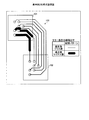
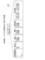
図1は、表示例1を示す説明図である。表示例1は、配線パスの違反線長の長さだけ配線パターンの描画色を変更する表示例である。表示例1では、まず、(A)ドライバ101−レシーバ102間のバス103で構成されたトポロジ100を線長制約条件に従って結線する。
<Display example 1>
FIG. 1 is an explanatory diagram illustrating a display example 1. Display example 1 is a display example in which the drawing color of the wiring pattern is changed by the length of the violation line length of the wiring path. In the display example 1, first, (A) the
線長制約条件では、条件名、パス名、線長、基準値、および違反値が規定されている。条件名とは、線長制約条件の条件名である。ここでは、BUS01が条件名である。なお、BUS01の線長条件として“±0.5mm”が規定されており、『各配線パスの線長は基準値(平均線長)から±0.5mm以内の等長配線』であることを意味している。なお、「等長」とは、線長条件を遵守する範囲の線長は線長制約条件を満たすことを意味している。 In the line length constraint condition, a condition name, path name, line length, reference value, and violation value are defined. The condition name is a condition name of a line length constraint condition. Here, BUS01 is the condition name. Note that “± 0.5 mm” is defined as the line length condition of BUS01, and that “the line length of each wiring path is equal length wiring within ± 0.5 mm from the reference value (average line length)”. I mean. Note that “equal length” means that the line length within the range of complying with the line length condition satisfies the line length constraint condition.
また、線長制約条件において、パス名は、線長制約条件で規定された配線パスの名称である。ここでは、バス103を構成する7本の配線パスの名称(path1〜path7)となる。 In the line length constraint condition, the path name is a name of the wiring path defined by the line length constraint condition. Here, the names of the seven wiring paths constituting the bus 103 (path1 to path7) are used.
基準値とは、線長制約条件に規定されている配線パス(ここでは、path1〜path7)の基準となる情報である。基準値には、たとえば、線長制約条件に規定されている配線パスから選ばれた特定の配線パスの線長や線長制約条件に規定されている配線パスの平均線長が用いられる。ここでは、平均線長を基準値としている。
The reference value is information serving as a reference for wiring paths (here,
違反値とは、線長制約条件の基準値の範囲より短い場合は不足している線長を、長い場合は超過している線長をいう。具体的には、任意の配線パスについて、線長が基準値よりも大きい場合は、配線パスの線長から等長となる上限線長を引いた正の値が違反線長となる。一方、線長が基準値より小さい場合は、配線パスの線長から等長となる下限線長を引いた負の値が違反線長となる。なお、配線パスの線長が等長(上限線長と下限線長との間の長さ)である場合は、線長制約条件を遵守していることとなる。 The violation value means an insufficient line length when it is shorter than the reference value range of the line length constraint condition, and an excess line length when it is longer. Specifically, for an arbitrary wiring path, when the line length is larger than the reference value, a positive value obtained by subtracting the upper limit line length that is the same length from the line length of the wiring path is the violation line length. On the other hand, when the line length is smaller than the reference value, a negative value obtained by subtracting the lower limit line length that is the same length from the line length of the wiring path is the violation line length. When the line length of the wiring path is the same length (the length between the upper limit line length and the lower limit line length), the line length constraint condition is observed.
たとえば、path1の線長は、130.000[mm]、基準値は121.714[mm]である。したがって、path1の線長130.000[mm]から、上限線長である122.214[mm](=121.714[mm]+0.5[mm])を減算すると、+8.786[mm](>0)となる。したがって、path1の線長は、8.786[mm]の長さ分超過していることとなる。
For example, the line length of path1 is 130.000 [mm], and the reference value is 121.714 [mm]. Therefore, by subtracting the upper limit line length of 122.214 [mm] (= 121.714 [mm] +0.5 [mm]) from the line length 130.000 [mm] of the
また、path4の線長は、120.000[mm]、基準値は121.714[mm]である。したがって、path4の線長120.000[mm]から、下限線長である121.214[mm](=121.714[mm]−0.5[mm])を減算すると、−1.214[mm](<0)となる。したがって、path4の線長は、1.214[mm]の長さ分不足していることとなる。
The line length of the
(B)の状態から、配線パスの配線パターンごとに、違反値の線長(以下、「違反線長」)分配線パターンに描画色を施してエラー表示とすることで、(C)の状態となる。描画する場合、違反値の正負によって描画色を異ならせる。なお、エラー表示がない配線パターンは、線長制約条件を遵守している配線パスである。 From the state of (B), for each wiring pattern of the wiring path, by drawing a color for the wiring pattern of the violation value (hereinafter referred to as “violating line length”) and displaying an error, the state of (C) It becomes. When drawing, the drawing color is changed depending on whether the violation value is positive or negative. A wiring pattern without an error display is a wiring path that complies with the line length constraint condition.
このように、表示例1では、どの配線パスに線長制約違反があるか、線長制約違反がある場合には、どのくらい違反しているのか、または、その違反が超過なのか不足なのかを、設計者に対して一つにまとめて示すことができる。したがって、設計者は、それぞれの配線パスをあとどれだけ短く/長くすれば等長にできそうかということを直感的に把握することができる。このため、線長制約条件に合うように配線パターンを効率的に編集することができる。 In this way, in display example 1, which wiring path has a line length constraint violation, if there is a line length constraint violation, how much is violated, or whether the violation is excessive or insufficient. , It can be shown together to the designer. Therefore, the designer can intuitively understand how much shorter / longer each wiring path can be made to be the same length. For this reason, the wiring pattern can be efficiently edited so as to meet the line length constraint condition.
<表示例2>
図2は、表示例2を示す説明図である。表示例1は違反値の正負により描画色を異ならせた表示例であるが、表示例2は、図1の(B)の状態から、配線パスの配線パターンごとに、違反線長分配線パターンの線幅を異ならせる表示例である。
<Display example 2>
FIG. 2 is an explanatory diagram showing a display example 2. The display example 1 is a display example in which the drawing color is changed depending on whether the violation value is positive or negative. The display example 2 is a wiring pattern corresponding to the violation line length for each wiring pattern of the wiring path from the state of FIG. This is a display example in which the line widths of are different.
図2では、一例として違反値が正(超過)の場合は違反線長分配線パターンの線幅を細くし、違反値が負(不足)の場合は違反線長分配線パターンの線幅を太くする。なお、図示はされていないが、配線パターンの線幅がすべて一定の配線パターンは、線長制約条件を遵守している配線パスである。 In FIG. 2, as an example, when the violation value is positive (excess), the line width of the violation line length is reduced, and when the violation value is negative (insufficient), the line width of the violation line length is increased. To do. Although not shown, a wiring pattern in which the line widths of all the wiring patterns are constant is a wiring path that complies with the line length constraint condition.
このように、表示例2では、表示例1と同様、どの配線パスに線長制約違反があるか、線長制約違反がある場合には、どのくらい違反しているのか、または、その違反が超過なのか不足なのかを、設計者に対して一つにまとめて示すことができる。したがって、設計者は、それぞれの配線パスをあとどれだけ短く/長くすれば等長にできそうかということを直感的に把握することができる。このため、線長制約条件に合うように配線パターンを効率的に編集することができる。 As described above, in display example 2, as in display example 1, in which wiring path there is a line length constraint violation, if there is a line length constraint violation, how much is violated or the violation is exceeded. It can be shown to the designer as a whole whether it is short or short. Therefore, the designer can intuitively understand how much shorter / longer each wiring path can be made to be the same length. For this reason, the wiring pattern can be efficiently edited so as to meet the line length constraint condition.
<表示例3>
図3は、表示例3を示す説明図である。表示例1は違反値の正負により描画色を異ならせた表示例であるが、表示例3は、図1の(B)の状態から、配線パスの配線パターンごとに、違反線長分配線パターンの線種を異ならせる表示例である。
<Display example 3>
FIG. 3 is an explanatory diagram showing a display example 3. Display example 1 is a display example in which the drawing color is changed depending on whether the violation value is positive or negative, but display example 3 is a wiring pattern corresponding to the length of the violation line for each wiring pattern of the wiring path from the state of FIG. This is a display example in which the line types of are different.
図3では、一例として違反値が正(超過)の場合は違反線長分配線パターンの線種を点線とし、違反値が負(不足)の場合は違反線長分配線パターンの線種を斜線を施した線とする。なお、図示はされていないが、配線パターンの線幅がすべて一定の配線パターンは、線長制約条件を遵守している配線パスである。 In FIG. 3, as an example, when the violation value is positive (exceeded), the line type of the violation line length wiring pattern is a dotted line, and when the violation value is negative (insufficient), the line type of the violation line length wiring pattern is hatched The line is marked with. Although not shown, a wiring pattern in which the line widths of all the wiring patterns are constant is a wiring path that complies with the line length constraint condition.
このように、表示例3では、表示例1と同様、どの配線パスに線長制約違反があるか、線長制約違反がある場合には、どのくらい違反しているのか、または、その違反が超過なのか不足なのかを、設計者に対して一つにまとめて示すことができる。したがって、設計者は、それぞれの配線パスをあとどれだけ短く/長くすれば等長にできそうかということを直感的に把握することができる。このため、線長制約条件に合うように配線パターンを効率的に編集することができる。 As described above, in display example 3, as in display example 1, in which wiring path there is a line length constraint violation, if there is a line length constraint violation, how much is violated or the violation is exceeded. It can be shown to the designer as a whole whether it is short or short. Therefore, the designer can intuitively understand how much shorter / longer each wiring path can be made to be the same length. For this reason, the wiring pattern can be efficiently edited so as to meet the line length constraint condition.
<表示例4>
図4は、表示例4を示す説明図である。表示例1は違反値の正負により描画色を異ならせた表示例であるが、表示例4は、図1の(B)の状態から、配線パスの配線パターンごとに、違反線長分配線パターンの図形を異ならせる表示例である。
<Display Example 4>
FIG. 4 is an explanatory diagram showing a display example 4. Display example 1 is a display example in which the drawing color is changed depending on whether the violation value is positive or negative, but display example 4 is a wiring pattern corresponding to the length of the violation line for each wiring pattern of the wiring path from the state of FIG. It is an example of a display which makes a figure of different.
図4では、一例として違反値が正(超過)の場合は違反線長分配線パターンの図形をハッチングを施した細長丸図形とし、違反値が負(不足)の場合は違反線長分配線パターンの図形を太長丸図形とする。なお、図示はされていないが、配線パターンの線幅がすべて一定の配線パターンは、線長制約条件を遵守している配線パスである。 In FIG. 4, for example, when the violation value is positive (exceeded), the figure of the violation line length wiring pattern is a hatched elongated round figure, and when the violation value is negative (insufficient), the violation line length wiring pattern The figure is a round and long figure. Although not shown, a wiring pattern in which the line widths of all the wiring patterns are constant is a wiring path that complies with the line length constraint condition.
このように、表示例4では、表示例1と同様、どの配線パスに線長制約違反があるか、線長制約違反がある場合には、どのくらい違反しているのか、または、その違反が超過なのか不足なのかを、設計者に対して一つにまとめて示すことができる。したがって、設計者は、それぞれの配線パスをあとどれだけ短く/長くすれば等長にできそうかということを直感的に把握することができる。このため、線長制約条件に合うように配線パターンを効率的に編集することができる。 As described above, in display example 4, as in display example 1, in which wiring path there is a line length constraint violation, if there is a line length constraint violation, how much is violated or the violation is exceeded. It can be shown to the designer as a whole whether it is short or short. Therefore, the designer can intuitively understand how much shorter / longer each wiring path can be made to be the same length. For this reason, the wiring pattern can be efficiently edited so as to meet the line length constraint condition.
<表示例5>
図5は、表示例5を示す説明図である。表示例1は違反値の正負により描画色を異ならせた表示例であるが、表示例5は、図1の(B)の状態から、配線パスの配線パターンごとに、配線パターンの違反線長に応じた色に描画する表示例である。
<Display Example 5>
FIG. 5 is an explanatory diagram showing a display example 5. The display example 1 is a display example in which the drawing color is changed depending on whether the violation value is positive or negative. The display example 5 is a violation line length of the wiring pattern for each wiring pattern of the wiring path from the state of FIG. It is an example of a display drawn in the color according to.
図5では、一例として、違反線長LがL>2.0[mm]、1.0[mm]<L≦2.0[mm]、0.0[mm]<L≦1.0[mm]、許容範囲(違反無し)、−1.0[mm]≦L<0.0[mm]、−2.0[mm]≦L<−1.0[mm]、L<−2.0[mm]ごとに色が異なるように描画する。許容範囲に応じた描画色は、線長制約条件を遵守している配線パスである。 In FIG. 5, as an example, the violation line length L is L> 2.0 [mm], 1.0 [mm] <L ≦ 2.0 [mm], 0.0 [mm] <L ≦ 1.0 [ mm], tolerance (no violation), −1.0 [mm] ≦ L <0.0 [mm], −2.0 [mm] ≦ L <−1.0 [mm], L <−2. Drawing is performed so that the color is different every 0 [mm]. The drawing color corresponding to the allowable range is a wiring path that complies with the line length restriction condition.
このように、表示例5では、表示例1と同様、どの配線パスに線長制約違反があるか、線長制約違反がある場合には、どのくらい違反しているのか、または、その違反が超過なのか不足なのかを、設計者に対して一つにまとめて示すことができる。したがって、設計者は、それぞれの配線パスをあとどれだけ短く/長くすれば等長にできそうかということを直感的に把握することができる。このため、線長制約条件に合うように配線パターンを効率的に編集することができる。 As described above, in display example 5, as in display example 1, in which wiring path there is a line length constraint violation, if there is a line length constraint violation, how much is violated or the violation is exceeded. It can be shown to the designer as a whole whether it is short or short. Therefore, the designer can intuitively understand how much shorter / longer each wiring path can be made to be the same length. For this reason, the wiring pattern can be efficiently edited so as to meet the line length constraint condition.
<表示例6>
図6は、表示例6を示す説明図である。表示例1において、線長制約条件において特定の配線パスが基準パスとなっている場合、基準パスの配線パターンを他の違反パスの配線パターンとは異なる色で描画する。図6では、path1の配線パターンが基準パスの配線パターンとなる。
<Display Example 6>
FIG. 6 is an explanatory diagram showing a display example 6. In the display example 1, when a specific wiring path is a reference path under the line length constraint condition, the wiring pattern of the reference path is drawn in a color different from the wiring patterns of other violation paths. In FIG. 6, the
このように、表示例6では、どの配線パスに線長制約違反があるか、線長制約違反がある場合には、どのくらい違反しているのか、または、その違反が超過なのか不足なのかを、設計者に対して一つにまとめて示すことができる。したがって、設計者は、基準パスまたは違反パスをあとどれだけ短く/長くすれば等長にできそうかということを直感的に把握することができる。このため、線長制約条件に合うように配線パターンを効率的に編集することができる。 In this way, in display example 6, it is shown which wiring path has a line length constraint violation, if there is a line length constraint violation, how much is violated, or whether the violation is excessive or insufficient. , It can be shown together to the designer. Therefore, the designer can intuitively understand how much the reference path or the violating path can be made to be the same length by making it shorter / longer. For this reason, the wiring pattern can be efficiently edited so as to meet the line length constraint condition.
<表示例7>
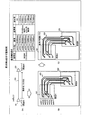
図7は、表示例7を示す説明図である。表示例1は、トポロジ100のドライバ101−レシーバ102間にダンピング抵抗が挿入されていない例であるが、表示例7は、トポロジ700のドライバ101−レシーバ102間の経路103にダンピング抵抗701が挿入された例である。すなわち、ダンピング抵抗701は、ドライバ101の近くに実装される。したがって、線長調整(長くする)する場合、ドライバ101とダンピング抵抗701の間の経路702ではなく、ダンピング抵抗701とレシーバ102との間の経路703で調整することとなる。
<Display example 7>
FIG. 7 is an explanatory diagram showing a display example 7. Display example 1 is an example in which a damping resistor is not inserted between the
したがって、表示例7では、ダンピング抵抗701が挿入されている場合にトポロジ700から線長調整すべき経路703を抽出し、抽出経路703に相当する配線パターンに対し、表示例1に示したように違反線長の描画を施すことになる。
Therefore, in the display example 7, when the damping
このように、表示例7では、表示例1と同様、どの配線パスに線長制約違反があるか、線長制約違反がある場合には、どのくらい違反しているのか、または、その違反が超過なのか不足なのかを、設計者に対して一つにまとめて示すことができる。したがって、設計者は、それぞれの配線パスをあとどれだけ短く/長くすれば等長にできそうかということを直感的に把握することができる。また、線長調整すべき経路に違反線長を描画することで、設計者は、どこで線長調整すべきかを考える必要がなく、線長調整のパターン編集に専念することができる。このため、線長制約条件に合うように配線パターンを効率的に編集することができる。 In this way, in display example 7, as in display example 1, which wiring path has a line length constraint violation, if there is a line length constraint violation, how much is violated, or the violation is exceeded. It can be shown to the designer as a whole whether it is short or short. Therefore, the designer can intuitively understand how much shorter / longer each wiring path can be made to be the same length. In addition, by drawing the violating line length on the path to be adjusted, the designer does not need to consider where the line length should be adjusted, and can concentrate on the pattern editing for the line length adjustment. For this reason, the wiring pattern can be efficiently edited so as to meet the line length constraint condition.
<表示例8>
図8は、表示例8を示す説明図である。表示例8は画面の拡大/縮小に応じて違反線長を表示する例である。たとえば、図8に示したレイアウトのうち、矩形で示した対象領域800に拡大して違反線長を表示する。すなわち、表示例8では、画面のサイズにかかわらず、各配線パターンの違反線長を把握することができるため、画面がどのようなサイズであっても、画面内において、どの配線パスに線長制約違反があるか、線長制約違反がある場合には、どのくらい違反しているのか、または、その違反が超過なのか不足なのかを、設計者に対して一つにまとめて示すことができる。したがって、設計者は、それぞれの配線パスをあとどれだけ短く/長くすれば等長にできそうかということを直感的に把握することができる。このため、線長制約条件に合うように配線パターンを効率的に編集することができる。
<Display example 8>
FIG. 8 is an explanatory diagram showing a display example 8. Display example 8 is an example in which the violation line length is displayed in accordance with the enlargement / reduction of the screen. For example, in the layout shown in FIG. 8, the violation line length is displayed by enlarging the
<表示例9>
図9は、表示例9を示す説明図である。表示例1や表示例7は、違反線長を線長調整すべき経路に表示させた例であるが、表示例9は、ユーザ操作の選択範囲900内で違反線長を表示する例である。表示例9では、選択範囲900内において、どの配線パスに線長制約違反があるか、線長制約違反がある場合には、どのくらい違反しているのか、または、その違反が超過なのか不足なのかを、設計者に対して一つにまとめて示すことができる。したがって、設計者は、それぞれの配線パスをあとどれだけ短く/長くすれば等長にできそうかということを直感的に把握することができる。このため、線長制約条件に合うように配線パターンを効率的に編集することができる。
<Display Example 9>
FIG. 9 is an explanatory diagram showing a display example 9. Display example 1 and display example 7 are examples in which the violation line length is displayed on the route whose line length should be adjusted. Display example 9 is an example in which the violation line length is displayed within the
<表示例10>
図10は、表示例10を示す説明図である。表示例1〜表示例9では、線長制約条件が1つの場合を例にして説明したが、表示例10は、線長制約条件が複数(図10では、条件1〜条件4の4つ)ある場合の表示例を示している。たとえば、条件1は、クロックおよびデータ(差動ペア)の配線パスを等長にする線長制約条件を示しており、条件2〜条件4は、差動ペアのペアネット間の配線パスを等長にする線長制約条件を示している。
<Display Example 10>
FIG. 10 is an explanatory diagram illustrating a display example 10. In the display examples 1 to 9, the case where there is one line length constraint condition has been described as an example. However, in the display example 10, there are a plurality of line length constraint conditions (four
表示例10では、表示例8のように対象領域を拡大した場合、拡大後の画面サイズに応じて配線パターンを線幅方向に分割して、複数の線長制約条件に応じた違反線長を表示する。配線パターンの線幅方向の分割数は、画面サイズに依存するため、分割数が制限されて全線長制約条件分割り当てられない場合がある。この場合は、線長制約条件の優先順位に従って割り当てることとする。このように、表示例10では、複数個の線長制約条件の違反線長を同一画面で同時に確認することができる。 In the display example 10, when the target area is enlarged as in the display example 8, the wiring pattern is divided in the line width direction according to the screen size after the enlargement, and the violation line lengths according to the plurality of line length constraint conditions are obtained. indicate. Since the number of divisions of the wiring pattern in the line width direction depends on the screen size, the number of divisions may be limited and may not be allocated for all line length constraints. In this case, the assignment is made in accordance with the priority order of the line length constraint conditions. As described above, in display example 10, violation line lengths of a plurality of line length constraint conditions can be simultaneously confirmed on the same screen.
このように、表示例10では、どの配線パスにどの程度の線長制約違反があるか、線長制約違反がある場合には、どのくらい違反しているのか、または、その違反が超過なのか不足なのかを、設計者に対して一つにまとめて示すことができる。したがって、設計者は、それぞれの配線パスをあとどれだけ短く/長くすれば等長にできそうかということを直感的に把握することができる。このため、複数の線長制約条件に合うように配線パターンを効率的に編集することができる。 As described above, in display example 10, how much line length constraint is violated in which wiring path, and how much is violated when there is a line length constraint violation, or whether the violation is excessive is insufficient. It can be shown to the designer as a whole. Therefore, the designer can intuitively understand how much shorter / longer each wiring path can be made to be the same length. Therefore, the wiring pattern can be efficiently edited so as to meet a plurality of line length constraint conditions.
<表示例11>
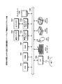
図11は、表示例11を示すブロック図である。表示例11では、違反線長の計算において先に線長調整が終了していることが前提となるケースにおいて、先に線長調整が必要な区間の配線パターンの線長調整が終了していなくても、線長調整が終えたと仮定したときの線長を計算で求める。その計算結果を用いて、違反線長を計算する。
<Display Example 11>
FIG. 11 is a block diagram illustrating a display example 11. In display example 11, in the case where it is assumed that the line length adjustment has been completed first in the calculation of the violating line length, the line length adjustment of the wiring pattern in the section where the line length adjustment needs to be completed first has not been completed. However, the line length when it is assumed that the line length adjustment has been completed is obtained by calculation. The violation line length is calculated using the calculation result.
具体的には、たとえば、図11に示したトポロジ1100において、ドライバ101〜レシーバ102間の経路702,703の線長制約条件を「条件1」、ドライバ101〜レシーバ1103間の経路1101の線長制約条件を「条件2」とする。条件2の違反線長を計算する場合、条件1での配線パスが等長にできたものとして計算する。すなわち、条件1での線長調整が終了していなくても、条件1の違反線長の長さを加算し、条件2の違反線長を計算することとなる。そして、レシーバ102〜レシーバ1103間の経路1102において、線長調整をおこなう。
Specifically, for example, in the
このように、表示例11では、前段の線長調整が終了していなくても、複数の線長制約条件の違反線長を同時に確認することができるため、線長調整の効率化を図ることができる。 As described above, in the display example 11, even if the line length adjustment in the previous stage is not completed, violation line lengths of a plurality of line length constraint conditions can be confirmed at the same time. Can do.
<表示例12>
図12は、表示例12を示す説明図である。表示例12では、配線パスが配線パターンとして形成されていない状態でも、違反線長を表示する例である。具体的には、配線パスの接続情報(たとえば、ラッツネット1201)から仮経路(たとえば、マンハッタン経路1202)を求め、それぞれの配線パスの仮経路の線長を求める。そして、仮経路の線長から違反線長を求めて仮経路上に表示する。このように、表示例12によれば、詳細な配線をしなくても、概略の違反線長を予測することができ、線長調整の効率化を図ることができる。
<Display Example 12>
FIG. 12 is an explanatory diagram illustrating a display example 12. Display example 12 is an example in which the violation line length is displayed even when the wiring path is not formed as a wiring pattern. Specifically, a temporary route (for example, Manhattan route 1202) is obtained from wiring path connection information (for example, a rats net 1201), and the line length of the temporary route of each wiring path is obtained. Then, the violation line length is obtained from the line length of the temporary route and displayed on the temporary route. As described above, according to the display example 12, an approximate violation line length can be predicted without performing detailed wiring, and the efficiency of line length adjustment can be improved.
<表示例13>
図13は、表示例13を示す説明図である。表示例13は、表示例1〜表示例12の少なくともいずれか2つを組み合わせた表示例である。図13においては、対象領域800を拡大表示する場合、対象領域800からはみ出した違反線長は、表示画面1300内で表現できない場合がある。この場合、線幅などを変更して重ねて表示することで、はみ出した違反線長も含めて違反線長の全長を表現することができる。
<Display Example 13>
FIG. 13 is an explanatory diagram illustrating a display example 13. Display example 13 is a display example in which at least any two of display examples 1 to 12 are combined. In FIG. 13, when the
(設計支援装置のハードウェア構成)
図14は、実施の形態にかかる設計支援装置のハードウェア構成を示すブロック図である。図14において、設計支援装置は、CPU(Central Processing Unit)1401と、ROM(Read‐Only Memory)1402と、RAM(Random Access Memory)1403と、磁気ディスクドライブ1404と、磁気ディスク1405と、光ディスクドライブ1406と、光ディスク1407と、ディスプレイ1408と、I/F(Interface)1409と、キーボード1410と、マウス1411と、スキャナ1412と、プリンタ1413と、を備えている。また、各構成部はバス1400によってそれぞれ接続されている。
(Hardware configuration of design support device)
FIG. 14 is a block diagram of a hardware configuration of the design support apparatus according to the embodiment. In FIG. 14, the design support apparatus includes a CPU (Central Processing Unit) 1401, a ROM (Read-Only Memory) 1402, a RAM (Random Access Memory) 1403, a
ここで、CPU1401は、設計支援装置の全体の制御を司る。ROM1402は、ブートプログラムなどのプログラムを記憶している。RAM1403は、CPU1401のワークエリアとして使用される。磁気ディスクドライブ1404は、CPU1401の制御にしたがって磁気ディスク1405に対するデータのリード/ライトを制御する。磁気ディスク1405は、磁気ディスクドライブ1404の制御で書き込まれたデータを記憶する。
Here, the
光ディスクドライブ1406は、CPU1401の制御にしたがって光ディスク1407に対するデータのリード/ライトを制御する。光ディスク1407は、光ディスクドライブ1406の制御で書き込まれたデータを記憶したり、光ディスク1407に記憶されたデータをコンピュータに読み取らせたりする。
The
ディスプレイ1408は、カーソル、アイコンあるいはツールボックスをはじめ、文書、画像、機能情報などのデータを表示する。このディスプレイ1408は、たとえば、CRT、TFT液晶ディスプレイ、プラズマディスプレイなどを採用することができる。 A display 1408 displays data such as a document, an image, and function information as well as a cursor, an icon, or a tool box. As this display 1408, for example, a CRT, a TFT liquid crystal display, a plasma display, or the like can be adopted.
インターフェース(以下、「I/F」と略する。)1409は、通信回線を通じてLAN(Local Area Network)、WAN(Wide Area Network)、インターネットなどのネットワーク1414に接続され、このネットワーク1414を介して他の装置に接続される。そして、I/F1409は、ネットワーク1414と内部のインターフェースを司り、外部装置からのデータの入出力を制御する。I/F1409には、たとえばモデムやLANアダプタなどを採用することができる。
An interface (hereinafter abbreviated as “I / F”) 1409 is connected to a
キーボード1410は、文字、数字、各種指示などの入力のためのキーを備え、データの入力をおこなう。また、タッチパネル式の入力パッドやテンキーなどであってもよい。マウス1411は、カーソルの移動や範囲選択、あるいはウィンドウの移動やサイズの変更などをおこなう。ポインティングデバイスとして同様に機能を備えるものであれば、トラックボールやジョイスティックなどであってもよい。
The
スキャナ1412は、画像を光学的に読み取り、設計支援装置内に画像データを取り込む。なお、スキャナ1412は、OCR(Optical Character Reader)機能を持たせてもよい。また、プリンタ1413は、画像データや文書データを印刷する。プリンタ1413には、たとえば、レーザプリンタやインクジェットプリンタを採用することができる。
The
(テーブルの記憶内容)
つぎに、本実施の形態で利用する各種テーブルの記憶内容について、図15〜図25を用いて説明する。以下のテーブルは、具体的には、たとえば、図14に示したROM1402、RAM1403、磁気ディスクドライブ1404および磁気ディスク1405、光ディスクドライブ1406および光ディスク1407などの記憶装置によりその機能を実現する。
(Table contents)
Next, storage contents of various tables used in the present embodiment will be described with reference to FIGS. Specifically, the functions of the following table are realized by storage devices such as the
図15は、ネットテーブル1500の記憶内容の一例を示す説明図である。ネットテーブル1500とは、ネットごとに、ネットを特定するネット番号とネット名とを対応付けたテーブルである。 FIG. 15 is an explanatory diagram showing an example of the contents stored in the net table 1500. The net table 1500 is a table in which a net number for identifying a net and a net name are associated with each net.
図16は、ランド形状テーブル1600の記憶内容の一例を示す説明図である。ランド形状テーブル1600とは、ランドごとに、ランドを特定するランド形状番号とランドの形状情報とを対応付けたテーブルである。形状情報とは、形状を特定する情報であり、たとえば、ランドの形状が矩形である場合、矩形(を示す識別子)と対角となる2つの頂点座標となる。また、ランドの形状が円である場合、円(を示す識別子)と中心座標と半径となる。 FIG. 16 is an explanatory diagram showing an example of the contents stored in the land shape table 1600. The land shape table 1600 is a table in which, for each land, a land shape number that identifies a land is associated with land shape information. The shape information is information for specifying the shape. For example, when the land shape is a rectangle, the shape information is two vertex coordinates that are diagonal to the rectangle (identifier indicating the rectangle). When the land shape is a circle, the circle (identifier indicating the circle), center coordinates, and radius are used.
図17は、部品ピンテーブル1700の記憶内容の一例を示す説明図である。部品ピンテーブル1700とは、部品ピンごとに、部品ピンを特定する部品ピン番号、部品ピンが属するネットのネット番号、部品ピンの座標位置、部品ピンが配置される階層番号、該当するランド形状番号を対応付けたテーブルである。 FIG. 17 is an explanatory diagram showing an example of the contents stored in the component pin table 1700. The component pin table 1700 is a component pin number for identifying a component pin, a net number of a net to which the component pin belongs, a coordinate position of the component pin, a hierarchy number at which the component pin is arranged, and a corresponding land shape number. Is a table in which
図18は、ビアテーブル1800の記憶内容の一例を示す説明図である。ビアテーブル1800とは、ビアごとに、ビアを特定するビア番号、ビアが属するネットのネット番号、ビアの座標位置、ビアが配置される階層番号、該当するランド形状番号を対応付けたテーブルである。 FIG. 18 is an explanatory diagram showing an example of the contents stored in the via table 1800. The via table 1800 is a table in which a via number for identifying a via, a net number of a net to which the via belongs, a coordinate position of the via, a hierarchy number at which the via is arranged, and a corresponding land shape number are associated with each via. .
図19は、ラインテーブル1900の記憶内容の一例を示す説明図である。ラインテーブル1900とは、ラインごとに、ラインを特定するライン番号、ラインが属するネットのネット番号、ラインのFrom−To座標位置、ラインの線幅、ラインが配線される階層番号を対応付けたテーブルである。ラインの線幅に従って描画すると配線パターンとなる。 FIG. 19 is an explanatory diagram showing an example of the contents stored in the line table 1900. The line table 1900 is a table in which, for each line, a line number that identifies the line, a net number of the net to which the line belongs, a From-To coordinate position of the line, a line width of the line, and a hierarchical number to which the line is wired are associated. It is. Drawing according to the line width of the line results in a wiring pattern.
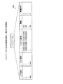
図20は、線長制約条件テーブル2000の記憶内容の一例を示す説明図である。線長制約条件テーブル2000とは、線長制約条件ごとに、線長制約条件を特定する制約条件番号、線長条件情報、線長基準情報、配線パス番号リスト、表示制御番号を対応付けたテーブルである。線長条件情報とは、線長制約条件が許容する範囲を示しており、線長条件情報を遵守する配線パスは基準パス、違反する配線パスは違反パスとなる。 FIG. 20 is an explanatory diagram of an example of the contents stored in the line length constraint condition table 2000. The line length constraint condition table 2000 is a table in which, for each line length constraint condition, a constraint condition number that specifies a line length constraint condition, line length condition information, line length reference information, a wiring path number list, and a display control number are associated with each other. It is. The line length condition information indicates a range allowed by the line length constraint condition. A wiring path that observes the line length condition information is a reference path, and an violating wiring path is a violating path.
制約条件番号は、図1または図10に示した条件名に対応する。線長基準情報とは、制約対象となる配線パスの基準を示す情報である。たとえば、特定の配線パスを基準とする場合、当該配線パスの配線パス番号(たとえば、配線パス番号2)が設定される。この場合、配線パス番号で特定される配線パスが基準パスとなる。また、制約対象となる配線パスの平均線長を線長基準情報としてもよい。線長基準情報で得られた値が、図1または図10に示した線長制約条件の基準値に相当する。 The constraint condition number corresponds to the condition name shown in FIG. The line length reference information is information indicating the reference of the wiring path to be restricted. For example, when a specific wiring path is used as a reference, a wiring path number (for example, wiring path number 2) of the wiring path is set. In this case, the wiring path specified by the wiring path number is the reference path. Further, the average line length of the wiring path to be restricted may be used as the line length reference information. The value obtained by the line length reference information corresponds to the reference value of the line length restriction condition shown in FIG.
また、配線パス番号リストとは、その線長制約条件が課される配線パスを特定する配線パス番号を列挙したリストである。線長基準情報は、配線パス番号リストに基づいて設定される。たとえば、特定の配線パス番号を線長基準情報とする場合、配線パス番号リストの中から選ばれる。同様に、配線パスの平均線長の場合、配線パス番号リストにより特定される配線パス群の平均線長となる。 The wiring path number list is a list in which wiring path numbers for specifying wiring paths on which the line length constraint condition is imposed are listed. The line length reference information is set based on the wiring path number list. For example, when a specific wiring path number is used as the line length reference information, it is selected from a wiring path number list. Similarly, in the case of the average line length of the wiring path, it is the average line length of the wiring path group specified by the wiring path number list.
図21は、配線パステーブル2100の記憶内容の一例を示す説明図である。配線パステーブル2100とは、配線パスごとに、配線パスを特定する配線パス番号、配線接続順要素リスト、線長、線長判定情報とを対応付けたテーブルである。 FIG. 21 is an explanatory diagram showing an example of the contents stored in the wiring path table 2100. The wiring path table 2100 is a table in which a wiring path number for specifying a wiring path, a wiring connection order element list, a line length, and line length determination information are associated with each other for each wiring path.
配線パス番号は、図1または図10に示した線長制約条件内のパス名に対応する。配線接続順要素リストとは、部品ピンやビアなどの配線要素を接続順に羅列したリストである。線長とは、配線パスの線長であり、図1または図10に示した線長制約条件内の線長に相当する。線長判定情報は、配線パスが線長制約条件を遵守したか違反したかの判定結果を示す情報である。「OK」である場合は、線長制約条件を遵守しており、数値である場合は、違反していることを示す。数値である場合、正の値であるときは、超過をあらわし、負の値であるときは、不足をあらわす。 The wiring path number corresponds to the path name in the line length constraint condition shown in FIG. The wiring connection order element list is a list in which wiring elements such as component pins and vias are arranged in the order of connection. The line length is the line length of the wiring path, and corresponds to the line length within the line length constraint condition shown in FIG. 1 or FIG. The line length determination information is information indicating a determination result of whether the wiring path complies with or violates the line length constraint condition. When it is “OK”, the line length restriction condition is observed, and when it is a numerical value, it indicates that it is violated. In the case of a numerical value, when it is a positive value, it indicates an excess, and when it is a negative value, it indicates a shortage.
図22は、表示パステーブル2200の記憶内容の一例を示す説明図である。表示パステーブル2200とは、表示パスごとに、線長番号、論理線長、仮線長、仮線長判定情報、表示区間番号リスト、同一パスリスト、親パス番号を対応付けた作業テーブルである。表示パスとは、配線パスのうち違反線長分のエラー表示の対象となるパスである。 FIG. 22 is an explanatory diagram showing an example of the contents stored in the display path table 2200. The display path table 2200 is a work table in which a line length number, a logical line length, a temporary line length, a temporary line length determination information, a display section number list, the same path list, and a parent path number are associated with each display path. . The display path is a path that is an error display target for the violation line length among the wiring paths.
線長番号は、図21に示した配線パステーブル2100の同一の配線パス番号に対応する。論理線長とは、表示パスに未配線区間がある場合に計算される線長である。仮線長とは、表示パスとなる配線パスの線長に対し、配線パステーブル2100の線長判定情報で得られた線長を考慮して計算された表示パスの仮の線長である。 The line length number corresponds to the same wiring path number in the wiring path table 2100 shown in FIG. The logical line length is a line length calculated when there is an unwired section in the display path. The temporary line length is a temporary line length of the display path calculated in consideration of the line length obtained from the line length determination information of the wiring path table 2100 with respect to the line length of the wiring path serving as the display path.
仮線長判定情報とは、表示パスの仮線長が線長制約条件を遵守したか違反したかの判定結果を示す情報である。「OK」である場合は、線長制約条件を遵守しており、数値である場合は、違反していることを示す。数値である場合、正の値であるときは、超過をあらわし、負の値であるときは、不足をあらわす。 The temporary line length determination information is information indicating a determination result as to whether the temporary line length of the display path complies with or violates the line length constraint condition. When it is “OK”, the line length restriction condition is observed, and when it is a numerical value, it indicates that it is violated. In the case of a numerical value, when it is a positive value, it indicates an excess, and when it is a negative value, it indicates a shortage.
表示区間番号リストとは、表示区間テーブル2300の表示区間番号を列挙した情報である。これにより、表示パスは列挙した番号順の表示区間を有することとなる。同一パスリストとは、その表示パスと制約条件は異なるが配線接続順要素リストが同一となる配線パスの配線パス番号を列挙した情報である。親パス番号とは、その表示パスの親パスとなる配線パス番号である。親パスとは、その表示パスとドライバが共通し、表示パスを包含する配線パスの中で最短の配線パスをいう。 The display section number list is information listing the display section numbers in the display section table 2300. As a result, the display path has display sections in the order of the listed numbers. The same path list is information that lists the wiring path numbers of wiring paths that have the same wiring connection order element list, although the display path is different from the restriction conditions. The parent path number is a wiring path number that is a parent path of the display path. The parent path is the shortest wiring path among the wiring paths that have the same display path and driver and encompass the display path.
図23は、表示区間テーブル2300の記憶内容の一例を示す説明図である。表示区間テーブル2300は、表示区間ごとに、表示区間を特定する表示区間番号、区間色、区間線幅、線種、図形種類、表示区間を対応付けた作業テーブルである。表示区間とは、対象となる経路であり、たとえば、ドライバ101とダンピング抵抗701との間の経路702である。区間色とは、表示区間の描画色である。区間線幅とは、表示区間に描画される違反線長分の線幅である。線種とは表示区間に描画される違反線長分の線の種類である。図形種類とは、表示区間に描画される違反線長分の図形種類である。
FIG. 23 is an explanatory diagram of an example of the contents stored in the display section table 2300. The display section table 2300 is a work table in which a display section number, a section color, a section line width, a line type, a figure type, and a display section that specify a display section are associated with each display section. The display section is a target path, for example, a
図24は、表示制御テーブル2400の記憶内容の一例を示す説明図である。表示制御テーブル2400とは、表示制御内容ごとに、表示制御内容を特定する表示制御番号、表示制御内容の詳細をあらわす表示方法番号リスト、違反線長となるエラー表示領域を対応付けたテーブルである。表示制御内容とは、どこにどのように違反線長のエラー表示をおこなうかを決定する情報である。表示方法番号リストとは、表示方法を特定する番号を列挙したリストである。表示方法については、図25において説明する。エラー表示領域とは、エラー表示させる領域を特定する領域を示している。 FIG. 24 is an explanatory diagram showing an example of the stored contents of the display control table 2400. The display control table 2400 is a table that associates, for each display control content, a display control number that specifies the display control content, a display method number list that represents details of the display control content, and an error display area that is a violation line length. . The display control content is information that determines where and how to display the error of the violation line length. The display method number list is a list in which numbers specifying display methods are listed. The display method will be described with reference to FIG. The error display area indicates an area for specifying an area for displaying an error.
図25は、表示方法テーブル2500の記憶内容の一例を示す説明図である。表示方法テーブル2500とは、表示方法ごとに、表示方法を特定する表示方法番号と表示方法とを対応付けたテーブルである。なお、本例では、表示方法番号は、図1〜図13に示した表示例1〜表示例13の番号(表示例#)に対応している。 FIG. 25 is an explanatory diagram of an example of the contents stored in the display method table 2500. The display method table 2500 is a table in which a display method number for specifying a display method is associated with a display method for each display method. In this example, the display method numbers correspond to the numbers (display example #) of display examples 1 to 13 shown in FIGS.
(設計支援処理手順)
つぎに、本実施の形態にかかる設計支援処理手順について説明する。
(Design support processing procedure)
Next, a design support processing procedure according to the present embodiment will be described.
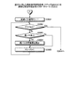
図26は、本実施の形態にかかる設計支援処理手順を示すフローチャートである。まず、作業テーブルを初期化する(ステップS2601)。作業テーブルとは、表示パステーブル2200と表示区間テーブル2300である。具体的には、表示パステーブル2200および表示区間テーブル2300の項目をすべて未定義にする。 FIG. 26 is a flowchart showing a design support processing procedure according to the present embodiment. First, the work table is initialized (step S2601). The work tables are a display path table 2200 and a display section table 2300. Specifically, all items in the display path table 2200 and the display section table 2300 are undefined.
つぎに、論理経路配線長算出処理(ステップS2602)、制約条件解釈処理(ステップS2603)、仮線長判定処理(ステップS2604)、表示区間決定処理(ステップS2605)、区間表示処理(ステップS2606)を実行する。これにより、一連の処理を終了する。つぎに、ステップS2602〜S2606の詳細な処理手順について説明する。 Next, logical route wiring length calculation processing (step S2602), constraint condition interpretation processing (step S2603), temporary line length determination processing (step S2604), display section determination processing (step S2605), and section display processing (step S2606). Run. As a result, the series of processes is completed. Next, a detailed processing procedure of steps S2602 to S2606 will be described.
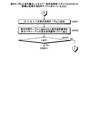
図27は、図26に示した論理経路配線長算出処理(ステップS2602)の詳細な処理手順を示すフローチャートである。論理経路配線長算出処理(ステップS2602)は、図22に示した表示パステーブル2200の「論理線長」項目を設定する処理である。したがって、表示例12の表示処理を実行する場合にのみ実行する。 FIG. 27 is a flowchart showing a detailed processing procedure of the logical route wiring length calculation processing (step S2602) shown in FIG. The logical route wiring length calculation process (step S2602) is a process for setting the “logical line length” item of the display path table 2200 shown in FIG. Therefore, it is executed only when the display process of the display example 12 is executed.
まず、制約条件番号CaをCa=1とし(ステップS2701)、Ca>Ncod(線長制約条件の総数)であるか否かを判断する(ステップS2702)。Ca>Ncodでない場合(ステップS2702:No)、リストのインデックス番号PIをPI=1とする(ステップS2703)。そして、PIが制約条件Caの配線パス番号リストの値の個数より大きいか否かを判断する(ステップS2704)。 First, the constraint condition number Ca is set to Ca = 1 (step S2701), and it is determined whether or not Ca> Ncod (total number of line length constraint conditions) (step S2702). If Ca> Ncod is not satisfied (step S2702: NO), the list index number PI is set to PI = 1 (step S2703). Then, it is determined whether PI is larger than the number of values in the wiring pass number list of the constraint condition Ca (step S2704).
PIが配線パス番号リストの値の個数以下の場合(ステップS2704:No)、配線パス番号リストのPI番目の値PaをPa=1とする(ステップS2705)。そして、配線パスPaの配線が完了したか否かを判断する(ステップS2706)。すなわち、配線パスPaが配線パターンとして描画されたか否かを判断する。 When PI is less than or equal to the number of values in the wiring path number list (step S2704: No), the PI-th value Pa in the wiring path number list is set to Pa = 1 (step S2705). Then, it is determined whether or not the wiring of the wiring path Pa is completed (step S2706). That is, it is determined whether or not the wiring path Pa is drawn as a wiring pattern.
完了した場合(ステップS2706:Yes)、ステップS2712に移行する。一方、完了していない場合(ステップS2706:No)、配線パステーブル2100を参照して、配線パスPaの既配線区間線長Laを抽出する(ステップS2707)。つぎに、配線パステーブル2100を参照して、配線パスPaの未結線区間Pbを抽出する(ステップS2708)。 If completed (step S2706: YES), the process proceeds to step S2712. On the other hand, if not completed (step S2706: No), the wiring path table 2100 is referred to extract the existing wiring section line length La of the wiring path Pa (step S2707). Next, the unconnected section Pb of the wiring path Pa is extracted with reference to the wiring path table 2100 (step S2708).
たとえば、Pa=1である場合、部品ピン1からビア1まで配線されている場合には、部品ピン1からビア1までの経路長を配線パスPaの既配線区間線長Laとして算出する。そして、ビア1から部品ピン8までが未結線となるため、ビア1から部品ピン8までの経路を配線パスPaの未結線区間Pbとして抽出する。そして、抽出された未結線区間Pbのマンハッタン長Lbを算出する(ステップS2709)。
For example, when Pa = 1, when the wiring from the
このあと、既配線区間線長Laと未結線区間Pbのマンハッタン長Lbとを合計することで、配線パスPaの論理線長Labとする(ステップS2710)。そして、表示パステーブル2200の配線パス番号Paのレコードに、論理線長Labを書き込む(ステップS2711)。このようにして、配線パスPaごとに論理線長Labを表示パステーブル2200に設定することができる。 Thereafter, the logical line length Lab of the wiring path Pa is obtained by summing the existing wiring section line length La and the Manhattan length Lb of the unconnected section Pb (step S2710). Then, the logical line length Lab is written in the record of the wiring path number Pa in the display path table 2200 (step S2711). In this way, the logical line length Lab can be set in the display path table 2200 for each wiring path Pa.
このあと、ステップS2712において、PIをインクリメントして(ステップS2712)、ステップS2704に戻る。そして、ステップS2704において、大きい場合(ステップS2704:Yes)、制約条件番号Caをインクリメントして(ステップS2713)、Ca>Ncod(線長制約条件の総数)であるか否かを判断する(ステップS2702)。 Thereafter, in step S2712, PI is incremented (step S2712), and the process returns to step S2704. In step S2704, if it is larger (step S2704: Yes), the constraint condition number Ca is incremented (step S2713), and it is determined whether or not Ca> Ncod (total number of line length constraint conditions) (step S2702). ).
Ca>Ncodである場合(ステップS2702:Yes)、論理経路配線長算出処理(ステップS2602)が完了し、制約条件解釈処理(ステップS2603)に移行する。 If Ca> Ncod (step S2702: YES), the logical route wiring length calculation process (step S2602) is completed, and the process proceeds to the constraint condition interpretation process (step S2603).
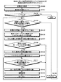
図28〜図30は、図26に示した制約条件解釈処理(ステップS2603)の詳細な処理手順を示すフローチャートである。制約条件解釈処理(ステップS2603)は、表示パステーブル2200の「同一パスリスト」項目、「パス番号リスト」項目、および「仮線長」項目を設定する処理である。したがって、表示例10や表示例11の表示処理を実行する場合にのみ実行する。 28 to 30 are flowcharts showing detailed processing procedures of the constraint condition interpretation processing (step S2603) shown in FIG. The constraint condition interpretation process (step S2603) is a process for setting the “same path list” item, the “pass number list” item, and the “temporary line length” item of the display path table 2200. Therefore, it is executed only when the display processing of display example 10 and display example 11 is executed.
まず、図28において、第1の制約条件番号C1をC1=1とし(ステップS2801)、C1>Ncod(線長制約条件の総数)であるか否かを判断する(ステップS2802)。C1>Ncodである場合(ステップS2802:Yes)、図30のステップS3001に移行する。 First, in FIG. 28, the first constraint condition number C1 is set to C1 = 1 (step S2801), and it is determined whether or not C1> Ncod (total number of line length constraint conditions) (step S2802). If C1> Ncod (step S2802: YES), the process proceeds to step S3001 in FIG.
一方、C1>Ncodでない場合(ステップS2802:No)、線長制約条件テーブル2000の制約条件C1の配線パス番号リストに、未選択の配線パス番号があるか否かを判断する(ステップS2803)。未選択の配線パス番号がある場合(ステップS2803:Yes)、未選択の配線パス番号をP1として抽出する(ステップS2804)。 On the other hand, if C1> Ncod is not satisfied (step S2802: NO), it is determined whether or not there is an unselected wiring path number in the wiring path number list of the constraint condition C1 in the line length constraint condition table 2000 (step S2803). If there is an unselected wiring path number (step S2803: YES), the unselected wiring path number is extracted as P1 (step S2804).
そして、図29のステップS2900に移行する。一方、ステップS2803において、未選択の配線パス番号がない場合(ステップS2803:No)、第1の制約条件番号C1をインクリメントして(ステップS2805)、ステップS2802に戻る。 Then, control goes to a step S2900 in FIG. On the other hand, if there is no unselected wiring path number in step S2803 (step S2803: No), the first constraint condition number C1 is incremented (step S2805), and the process returns to step S2802.
つぎに、図29において、第2の制約条件番号C2をC2=1とし(ステップS2900)、C2>Ncod(線長制約条件の総数)であるか否かを判断する(ステップS2901)。C2>Ncodである場合(ステップS2901:Yes)、図28のステップS2803に戻る。 Next, in FIG. 29, the second constraint condition number C2 is set to C2 = 1 (step S2900), and it is determined whether or not C2> Ncod (total number of line length constraint conditions) (step S2901). When C2> Ncod is satisfied (step S2901: YES), the process returns to step S2803 in FIG.
一方、C2>Ncodでない場合(ステップS2901:No)、線長制約条件テーブル2000の制約条件C2の配線パス番号リストに、未選択の配線パス番号があるか否かを判断する(ステップS2902)。未選択の配線パス番号がある場合(ステップS2902:Yes)、未選択の配線パス番号をP2として抽出する(ステップS2903)。 On the other hand, if C2> Ncod is not satisfied (step S2901: NO), it is determined whether or not there is an unselected wiring path number in the wiring path number list of the constraint condition C2 of the line length constraint condition table 2000 (step S2902). If there is an unselected wiring path number (step S2902: YES), the unselected wiring path number is extracted as P2 (step S2903).
そして、C1≠C2でかつP1=P2であるか否かを判断する(ステップS2904)。すなわち、同一配線パスにつき、2つ(C1およびC2)の線長制約条件があるかを判断する。C1≠C2でかつP1=P2でない場合(ステップS2904:No)、ステップS2906に移行する。一方、C1≠C2でかつP1=P2である場合(ステップS2904:Yes)、配線パスP1(=P2)の同一パスリストを更新する(ステップS2905)。具体的には、表示パステーブル2200において、配線パス番号P1に対応する線長番号P1のレコードの同一パスリストに、配線パス番号P1(=P2)を書き込む。 Then, it is determined whether C1 ≠ C2 and P1 = P2 (step S2904). That is, it is determined whether there are two (C1 and C2) line length constraint conditions for the same wiring path. If C1 ≠ C2 and P1 = P2 is not satisfied (step S2904: NO), the process proceeds to step S2906. On the other hand, if C1 ≠ C2 and P1 = P2 (step S2904: Yes), the same path list of the wiring path P1 (= P2) is updated (step S2905). Specifically, in the display path table 2200, the wiring path number P1 (= P2) is written in the same path list of the record of the line length number P1 corresponding to the wiring path number P1.
そして、C1≠C2でかつP1⊂P2であるか否かを判断する(ステップS2906)。すなわち、線長制約条件が異なる場合に、配線パスP1が配線パスP2の一部であるか否かを判断する。C1≠C2でかつP1⊂P2でない場合(ステップS2906:No)、ステップS2902に戻る。一方、C1≠C2でかつP1⊂P2である場合(ステップS2906:Yes)、配線パスP1,P2の親パス番号を収集して配線パス集合M1を設定する(ステップS2907)。 Then, it is determined whether C1 ≠ C2 and P1⊂P2 (step S2906). That is, when the line length constraint conditions are different, it is determined whether or not the wiring path P1 is a part of the wiring path P2. If C1 ≠ C2 and P1⊂P2 is not satisfied (step S2906: NO), the process returns to step S2902. On the other hand, if C1 ≠ C2 and P1⊂P2 (step S2906: YES), the parent path numbers of the wiring paths P1 and P2 are collected to set the wiring path set M1 (step S2907).
ステップS2907では、親パス番号が未定義の場合、配線パス集合M1をM1={P1,P2}とする。また、配線パスP1,P2に親パスがある場合、配線パス集合M1にその親パスを含めることとなる。 In step S2907, if the parent path number is undefined, the wiring path set M1 is set to M1 = {P1, P2}. When the wiring paths P1 and P2 have a parent path, the parent path is included in the wiring path set M1.
そして、配線パス集合M1の配線パスの並びを線長が短い順にソートし(ステップS2908)、ソート後の配線パス集合M1から親パス番号を特定して、表示パステーブル2200を更新する(ステップS2909)。そして、ステップS2902に戻る。一方、ステップS2902において、未選択の配線パス番号がない場合(ステップS2902:No)、第2の制約条件番号C2をインクリメントして(ステップS2910)、ステップS2901に戻る。 The arrangement of the wiring paths in the wiring path set M1 is sorted in ascending order of the line length (step S2908), the parent path number is specified from the sorted wiring path set M1, and the display path table 2200 is updated (step S2909). ). Then, the process returns to step S2902. On the other hand, if there is no unselected wiring path number in step S2902 (step S2902: No), the second constraint condition number C2 is incremented (step S2910), and the process returns to step S2901.
また、図28において、C1>Ncodである場合(ステップS2802:Yes)、図30のステップS3001に移行する。ステップS3001において、配線パス番号P3をP3=1とし(ステップS3001)、P3>Npthであるか否かを判断する(ステップS3002)。P3>Npthでない場合(ステップS3002:No)、配線パスP3に親パスがあるか否かを判断する(ステップS3003)。 In FIG. 28, if C1> Ncod (step S2802: YES), the process proceeds to step S3001 in FIG. In step S3001, the wiring path number P3 is set to P3 = 1 (step S3001), and it is determined whether P3> Npth is satisfied (step S3002). If P3> Npth is not satisfied (step S3002: NO), it is determined whether or not the wiring path P3 has a parent path (step S3003).
親パスがある場合(ステップS3003:Yes)、親パスの仮線長を算出し(ステップS3004)、ステップS3005に移行する。一方、親パスがない場合(ステップS3003:No)、ステップS3005に移行する。ステップS3005では、配線パス番号P3をインクリメントし(ステップS3005)、ステップS3002に移行する。そして、P3>Npthである場合(ステップS3002:Yes)、制約条件解釈処理(ステップS2603)が完了し、仮線長判定処理(ステップS2604)に移行する。 If there is a parent path (step S3003: Yes), the temporary path length of the parent path is calculated (step S3004), and the process proceeds to step S3005. On the other hand, when there is no parent path (step S3003: No), the process proceeds to step S3005. In step S3005, the wiring pass number P3 is incremented (step S3005), and the process proceeds to step S3002. If P3> Npth (step S3002: Yes), the constraint condition interpretation process (step S2603) is completed, and the process proceeds to the temporary line length determination process (step S2604).
ここで、制約条件解釈処理(ステップS2603)の具体例について説明する。まず、表示パステーブル2200の親パス番号の更新例について図31〜図33を用いて説明する。 Here, a specific example of the constraint condition interpretation process (step S2603) will be described. First, an example of updating the parent path number in the display path table 2200 will be described with reference to FIGS.
図31は、表示パステーブル2200の親パス番号の更新例を説明するためのトポロジの一例を示す説明図であり、図32は、図31のトポロジに応じた配線パステーブル2100の記憶内容を示す説明図であり、図33は、表示パステーブル2200の更新例を示す説明図である。なお、配線パステーブル2100と表示パステーブル2200については、項目を一部抜粋している。図33の(A)は、表示パステーブル2200の初期状態を示している。 FIG. 31 is an explanatory diagram showing an example of a topology for explaining an example of updating the parent path number of the display path table 2200, and FIG. 32 shows the storage contents of the wiring path table 2100 corresponding to the topology of FIG. FIG. 33 is an explanatory diagram showing an example of updating the display path table 2200. Note that some items of the wiring path table 2100 and the display path table 2200 are extracted. FIG. 33A shows an initial state of the display path table 2200.
まず、P1=1、P2=2の場合、表示パステーブル2200を参照すると、配線パス番号1(=P1)に対応する線長番号1の親パス番号は未定義である。同様に、配線パス番号2(=P2)に対応する線長番号2の親パス番号も未定義である。したがって、配線パス集合M1は、M1={P1,P2}={1,2}となる。
First, in the case of P1 = 1 and P2 = 2, referring to the display path table 2200, the parent path number of the
そして、配線パス集合M1を線長の短い順にソートすると、M1={P1,P2}={1,2}となる。配線パス集合M1内の並びで、隣接する配線パス番号のうち、右側の番号が左側の番号の親となる。したがって、配線パス番号1の親パスは配線パス番号2となる。これにより、図33の(B)に示したように、表示パステーブル2200の配線パス番号1に対応する線長番号1の親パス番号に「2」が書き込まれる。
Then, when the wiring path set M1 is sorted in order of increasing line length, M1 = {P1, P2} = {1, 2}. Of the adjacent wiring path numbers in the arrangement in the wiring path set M1, the right number is the parent of the left number. Therefore, the parent path of the
つぎに、P1=1、P2=3となった場合、配線パス集合M1としてP1,P3のほか、P1の親パス番号2を図33の(B)の表示パステーブル2200から引く。これにより、配線パス集合M1={P1,P3,P2}={1,3,2}となる。
Next, when P1 = 1 and P2 = 3, the
そして、配線パス集合M1を線長の短い順にソートすると、M1={1,2,3}となる。配線パス集合M1内の並びで、隣接する配線パス番号のうち、右側の番号が左側の番号の親となる。したがって、配線パス番号2の親パスは配線パス番号3となる。これにより、図33の(C)に示したように、表示パステーブル2200の配線パス番号2に対応する線長番号2の親パス番号に「3」が書き込まれる。
Then, when the wiring path set M1 is sorted in order of increasing line length, M1 = {1, 2, 3}. Of the adjacent wiring path numbers in the arrangement in the wiring path set M1, the right number is the parent of the left number. Therefore, the parent path of the
このあと、ステップS3004に示したように、親パスの仮線長を求める。配線パス番号P3=1の場合、配線パスP3(=1)の親パス番号は「2」であるため、親パス番号2である配線パス番号2の線長「13000」から配線パスP3(=1)の線長判定情報「−1000」を引くことにより、配線パス番号(線長番号)2の仮線長「14000(=13000−(−1000))」を求めることができる。そして、図33の(D)に示したように、線長番号2の仮線長に「14000」を書き込む。
Thereafter, as shown in step S3004, the temporary line length of the parent path is obtained. When the wiring path number P3 = 1, since the parent path number of the wiring path P3 (= 1) is “2”, the wiring path P3 (=) from the line length “13000” of the
つぎに、配線パス番号P3=2の場合、配線パスP3(=2)の親パス番号は「3」であるため、親パス番号3である配線パス番号3の線長「17000」から配線パスP3(=2)の線長判定情報「−2000」を引くことにより、配線パス番号(線長番号)3の仮線長「19000(=17000−(−2000))」を求めることができる。そして、図33の(E)に示したように、線長番号3の仮線長に「19000」を書き込む。
Next, when the wiring path number P3 = 2, since the parent path number of the wiring path P3 (= 2) is “3”, the wiring path from the line length “17000” of the
なお、この例では、仮線長が未定義であるため、配線パステーブル2100の線長を適用したが、表示パステーブル2200において論理線長が設定されている場合には、線長にかえて論理線長を用いる。また、すでに仮線長が得られている場合は、線長判定情報を使わずに仮線長をそのまま設定する。 In this example, since the temporary line length is undefined, the line length of the wiring path table 2100 is applied. However, when the logical line length is set in the display path table 2200, the line length is changed. Use logical line length. If the temporary line length has already been obtained, the temporary line length is set as it is without using the line length determination information.
図34は、図26に示した仮線長判定処理(ステップS2604)の詳細な処理手順を示すフローチャートである。仮線長判定処理(ステップS2604)では、表示パステーブル2200の「仮線長判定情報」項目を設定する処理である。したがって、表示例11や表示例12の表示処理を実行する場合にのみ実行する。 FIG. 34 is a flowchart showing a detailed processing procedure of the temporary line length determination processing (step S2604) shown in FIG. The provisional line length determination process (step S2604) is a process for setting the “provisional line length determination information” item of the display path table 2200. Therefore, it is executed only when the display processing of display example 11 and display example 12 is executed.
まず、制約条件番号CをC=1とし(ステップS3401)、C>Ncod(線長制約条件の総数)であるか否かを判断する(ステップS3402)。C>Ncodでない場合(ステップS3402:No)、制約条件番号Cの配線パス番号リストに未選択の配線パス番号があるか否かを判断する(ステップS3403)。未選択の配線パス番号がない場合(ステップS3403:No)、制約条件番号Cをインクリメントし(ステップS3404)、ステップS3402に戻る。 First, the constraint condition number C is set to C = 1 (step S3401), and it is determined whether or not C> Ncod (total number of line length constraint conditions) (step S3402). If C> Ncod is not satisfied (step S3402: NO), it is determined whether or not there is an unselected wiring path number in the wiring path number list of the constraint condition number C (step S3403). If there is no unselected wiring path number (step S3403: NO), the constraint condition number C is incremented (step S3404), and the process returns to step S3402.
そして、ステップS3402において、C>Ncod(線長制約条件の総数)である場合(ステップS3402:Yes)、ステップS2605に移行する。一方、未選択の配線パス番号がある場合(ステップS3403:Yes)、制約条件Cの基準値CSを算出する(ステップS3405)。具体的には、線長制約条件テーブル2000の線長基準情報を参照して、基準値CS(特定の配線パスの線長、制約対象の配線パスの平均線長)を算出する。 In step S3402, if C> Ncod (total number of line length constraint conditions) (step S3402: YES), the process proceeds to step S2605. On the other hand, when there is an unselected wiring path number (step S3403: YES), the reference value CS of the constraint condition C is calculated (step S3405). Specifically, the reference value CS (line length of a specific wiring path, average line length of a restriction target wiring path) is calculated with reference to the line length reference information in the line length restriction condition table 2000.
このあと、ステップS3403での未選択の配線パス番号Pを抽出する(ステップS3406)。そして、表示パステーブル2200において、選択された配線パス番号P(=線長番号P)の仮線長が未定義か否かを判断する(ステップS3407)。未定義でない場合(ステップS3407:No)、配線パス番号Pの仮線長を比較対象線長LPに設定して(ステップS3408)、ステップS3412に移行する。 Thereafter, the unselected wiring path number P in step S3403 is extracted (step S3406). Then, in the display path table 2200, it is determined whether or not the temporary line length of the selected wiring path number P (= line length number P) is undefined (step S3407). If it is not undefined (step S3407: No), the temporary line length of the wiring pass number P is set to the comparison target line length LP (step S3408), and the process proceeds to step S3412.
一方、選択された配線パス番号P(=線長番号P)の仮線長が未定義である場合(ステップS3407:Yes)、選択された配線パス番号P(=線長番号P)の論理線長が未定義であるか否かを判断する(ステップS3409)。未定義でない場合(ステップS3409:No)、配線パス番号Pの論理線長を比較対象線長LPに設定して(ステップS3410)、ステップS3412に移行する。 On the other hand, if the temporary line length of the selected wiring path number P (= line length number P) is undefined (step S3407: Yes), the logical line of the selected wiring path number P (= line length number P) It is determined whether or not the length is undefined (step S3409). If it is not undefined (step S3409: No), the logical line length of the wiring path number P is set to the comparison target line length LP (step S3410), and the process proceeds to step S3412.
一方、選択された配線パス番号P(=線長番号P)の論理線長が未定義である場合(ステップS3409:Yes)、配線パス番号Pの線長を比較対象線長LPに設定して(ステップS3411)、ステップS3412に移行する。 On the other hand, when the logical line length of the selected wiring path number P (= line length number P) is undefined (step S3409: Yes), the line length of the wiring path number P is set as the comparison target line length LP. (Step S3411), the process proceeds to Step S3412.
ステップS3412では、仮線長判定情報HをH=LP−CSを計算することで求める。そして、求めた仮線長判定情報Hを、表示パステーブル2200の配線パス番号P(=線長番号P)のレコードに書き込み(ステップS3413)、ステップS3403に戻る。 In step S3412, the temporary line length determination information H is obtained by calculating H = LP-CS. Then, the calculated temporary line length determination information H is written in the record of the wiring path number P (= line length number P) in the display path table 2200 (step S3413), and the process returns to step S3403.
図35は、仮線長判定情報が書き込まれた表示パステーブル2200を示す説明図である。図35の表示パステーブル2200は、図33の(E)に示した状態からの更新例である。たとえば、P=3の基準値は、「20000」であるため、仮線長「19000」は「1000」不足している。したがって、仮線長判定情報H=−1000となる。 FIG. 35 is an explanatory diagram showing a display path table 2200 in which temporary line length determination information is written. The display path table 2200 in FIG. 35 is an example of update from the state shown in FIG. For example, since the reference value for P = 3 is “20000”, the temporary line length “19000” is insufficient for “1000”. Therefore, provisional line length determination information H = −1000.
また、図34に戻り、ステップS3402において、C>Ncodである場合(ステップS3402:Yes)、仮線長判定処理(ステップS2604)を完了し、表示区間決定処理(ステップS2605)に移行する。 Returning to FIG. 34, if C> Ncod in step S3402 (step S3402: YES), the provisional line length determination process (step S2604) is completed, and the process proceeds to the display section determination process (step S2605).
図36は、図26に示した表示区間決定処理(ステップS2605)の詳細な処理手順を示すフローチャートである。表示区間決定処理(ステップS2605)は、表示区間テーブル2300を作成する処理である。 FIG. 36 is a flowchart of a detailed process procedure of the display section determination process (step S2605) depicted in FIG. The display section determination process (step S2605) is a process for creating the display section table 2300.
まず、制約条件番号CをC=1とし(ステップS3601)、C>Ncod(線長制約条件の総数)であるか否かを判断する(ステップS3602)。C>Ncodでない場合(ステップS3602:No)、制約条件番号Cの配線パス番号リストに未選択の配線パス番号があるか否かを判断する(ステップS3603)。未選択の配線パス番号がない場合(ステップS3603:No)、制約条件番号Cをインクリメントし(ステップS3614)、ステップS3602に戻る。 First, the constraint condition number C is set to C = 1 (step S3601), and it is determined whether or not C> Ncod (total number of line length constraint conditions) (step S3602). If C> Ncod is not satisfied (step S3602: NO), it is determined whether or not there is an unselected wiring path number in the wiring path number list of the constraint condition number C (step S3603). If there is no unselected wiring path number (step S3603: No), the constraint condition number C is incremented (step S3614), and the process returns to step S3602.
一方、未選択の配線パス番号がある場合(ステップS3603:Yes)、未選択の配線パス番号Pとして抽出し(ステップS3604)、配線パス番号Pが基準パスであるか否かを判断する(ステップS3605)。具体的には、図21に示した配線パステーブル2100を参照して、配線パス番号Pの配線パス(以下、配線パスP)の線長判定情報がOKであるか否かを判断する。OKであれば基準パスとなる。 On the other hand, if there is an unselected wiring path number (step S3603: Yes), it is extracted as an unselected wiring path number P (step S3604), and it is determined whether the wiring path number P is a reference path (step S3604). S3605). Specifically, with reference to the wiring path table 2100 shown in FIG. 21, it is determined whether or not the line length determination information of the wiring path with the wiring path number P (hereinafter, wiring path P) is OK. If it is OK, it becomes a reference path.
基準パスでない場合(ステップS3605:No)、配線パスPの区間G1を設定する(ステップS3606)。具体的には、区間G1に、配線パスPの配線接続順要素リストの要素を入れる。そして、制約条件Cの表示制御番号から表示制御テーブル2400を参照し、その表示方法番号リストM1を特定する(ステップS3607)。このあと、区間特定処理(ステップS3608)および重ね書きによるエラー長表現処理(ステップS3609)を実行して、ステップS3603に戻る。区間特定処理(ステップS3608)および重ね書きによるエラー長表現処理(ステップS3609)については後述する。 If it is not the reference path (step S3605: No), the section G1 of the wiring path P is set (step S3606). Specifically, an element of the wiring connection order element list of the wiring path P is entered in the section G1. Then, the display control table 2400 is referred to from the display control number of the constraint condition C, and the display method number list M1 is specified (step S3607). Thereafter, the section specifying process (step S3608) and the error length expression process (step S3609) by overwriting are executed, and the process returns to step S3603. The section specifying process (step S3608) and the error length expression process (step S3609) by overwriting will be described later.
一方、ステップS3605において、配線パスPが基準パスである場合(ステップS3605:Yes)、基準パスPの表示区間Qを作成する(ステップS3610)。また、基準パスPの描画色Dを設定する(ステップS3611)。このとき、描画色Dは予め設定された描画色Dとする。 On the other hand, when the wiring path P is the reference path in step S3605 (step S3605: Yes), the display section Q of the reference path P is created (step S3610). In addition, the drawing color D of the reference path P is set (step S3611). At this time, the drawing color D is set to a preset drawing color D.
そして、[Q,D]を表示区間テーブル2300に追加する(ステップS3612)。具体的には、特定の表示区間番号のレコードに対し、Dを「区間色」項目に、Qを「表示区間」項目に書き込む。そして、[Q,D]が追加された表示区間番号を、表示パステーブル2200の基準パスPのレコードの表示区間番号リストに追加する(ステップS3613)。このあと、ステップS3603に戻る。 [Q, D] is added to the display section table 2300 (step S3612). Specifically, D is written in the “section color” item and Q is written in the “display section” item for a record of a specific display section number. Then, the display section number to which [Q, D] is added is added to the display section number list of the record of the reference path P in the display path table 2200 (step S3613). Thereafter, the process returns to step S3603.
一方、ステップS3602において、C>Ncodである場合(ステップS3602:Yes)、表示区間決定処理(ステップS2605)を完了し、区間表示処理(ステップS2606)に移行する。 On the other hand, if C> Ncod in step S3602 (step S3602: Yes), the display section determination process (step S2605) is completed, and the process proceeds to the section display process (step S2606).
図37は、図36に示した区間特定処理(ステップS3608)の詳細な処理手順を示すフローチャートである。まず、ステップS3607で取得した表示方法番号リストM1に未選択の表示方法番号Rがあるか否かを判断する(ステップS3701)。未選択の表示方法番号がある場合(ステップS3701:Yes)、未選択の表示方法番号Rを選択する(ステップS3702)。そして、選択された表示方法番号Rが、R=7〜9以外の番号か、R=7か、R=8か、R=9かを判断する(ステップS3703)。 FIG. 37 is a flowchart showing a detailed processing procedure of the section specifying process (step S3608) shown in FIG. First, it is determined whether or not there is an unselected display method number R in the display method number list M1 acquired in step S3607 (step S3701). If there is an unselected display method number (step S3701: YES), an unselected display method number R is selected (step S3702). Then, it is determined whether the selected display method number R is a number other than R = 7 to 9, R = 7, R = 8, or R = 9 (step S3703).
R=7〜9以外の番号である場合(ステップS3703:7〜9以外)、線長調整対象区間G2を空にして(ステップS3704)、ステップS3708に移行する。 When R is a number other than 7-9 (step S3703: other than 7-9), the line length adjustment target section G2 is emptied (step S3704), and the process proceeds to step S3708.
また、R=7である場合(ステップS3703:7)、配線パスPのトポロジから線長調整対象区間G2を特定して(ステップS3705)、ステップS3708に移行する。具体的には、回路トポロジデータベース(DB)を用いる。回路トポロジDBには、線長調整対象区間が指定されたトポロジが各種記憶されている。したがって、回路トポロジDBの中から配線パスPのトポロジと一致するトポロジを検索し、検索されたトポロジに指定されている線長調整対象区間を抽出する。この抽出された線長調整対象区間をG2として特定する。 If R = 7 (step S3703: 7), the line length adjustment target section G2 is specified from the topology of the wiring path P (step S3705), and the process proceeds to step S3708. Specifically, a circuit topology database (DB) is used. In the circuit topology DB, various topologies in which the line length adjustment target section is designated are stored. Accordingly, the topology that matches the topology of the wiring path P is searched from the circuit topology DB, and the line length adjustment target section specified in the searched topology is extracted. The extracted line length adjustment target section is specified as G2.
また、R=8である場合(ステップS3703:8)、配線パスPの区間G1において画面表示範囲内に含まれる区間G2を特定して(ステップS3706)、ステップS3708に移行する。たとえば、配線パスPの区間G1のうち図8に示した対象領域800に含まれる区間G2を検出する。
When R = 8 (step S3703: 8), the section G2 included in the screen display range in the section G1 of the wiring path P is specified (step S3706), and the process proceeds to step S3708. For example, the section G2 included in the
また、R=9である場合(ステップS3703:9)、配線パスPの区間G1においてエラー表示領域内に含まれる区間G2を特定して(ステップS3707)、ステップS3708に移行する。たとえば、配線パスPの区間G1のうち図9に示した選択範囲900に含まれる区間G2を検出する。
If R = 9 (step S3703: 9), the section G2 included in the error display area in the section G1 of the wiring path P is specified (step S3707), and the process proceeds to step S3708. For example, the section G2 included in the
そして、ステップS3708では、区間G2が空でないかを判断し(ステップS3708)、空である場合(ステップS3708:No)、ステップS3701に戻る。一方、空でない場合(ステップS3708:Yes)、配線パスPの区間G1を線長調整対象区間G2とし(ステップS3709)、ステップS3701に戻る。そして、未選択の表示方法番号Rがない場合(ステップS3701:No)、重ね書きによるエラー長表現処理(ステップS3609)に移行する。 In step S3708, it is determined whether the section G2 is not empty (step S3708). If it is empty (step S3708: No), the process returns to step S3701. On the other hand, if it is not empty (step S3708: Yes), the section G1 of the wiring path P is set as the line length adjustment target section G2 (step S3709), and the process returns to step S3701. If there is no display method number R that has not been selected (step S3701: NO), the process proceeds to error length expression processing (step S3609) by overwriting.
図38〜図40は、図36に示した重ね書きによるエラー長表現処理(ステップS3609)の詳細な処理手順を示すフローチャートである。まず、基準パスではない配線パスPの区間G1に含まれている区間Qを設定する(ステップS3801)。たとえば、P=1の場合、図21の配線パス番号1では、「部品ピン1、ビア1、ビア8、部品ピン8」であるため、区間[部品ピン1,ビア1]、区間[ビア1,ビア8]、区間[ビア8,部品ピン8]の各々が区間Qとして設定される。
38 to 40 are flowcharts showing the detailed processing procedure of the error length expression processing (step S3609) by overwriting shown in FIG. First, the section Q included in the section G1 of the wiring path P that is not the reference path is set (step S3801). For example, when P = 1, the
また、表示方法変数ZをZ=0とする(ステップS3802)。そして、配線パスPの仮線長判定情報の絶対値Lを取得する(ステップS3803)。つぎに、区間Qの線長総和LQを算出する(ステップS3804)。そして、LQ≧Lであるか否かを判断する(ステップS3805)。 Further, the display method variable Z is set to Z = 0 (step S3802). Then, the absolute value L of the temporary line length determination information of the wiring path P is acquired (step S3803). Next, the total line length LQ of the section Q is calculated (step S3804). Then, it is determined whether or not LQ ≧ L (step S3805).
LQ≧Lでない場合(ステップS3805:No)、ステップS3807に移行する。一方、LQ≧Lである場合(ステップS3805:Yes)、線長総和LQをLQ=Lとし、仮線長判定情報の絶対値LをL=L―LQとする(ステップS3806)。なお、LQ=Lとしたため、その分、区間Qの座標値も変動することになる。変動については、どのような処理でもよく、区間Qのうち末尾の区間のみ短くしてもよく、すべての区間Qを均等に短くしてもよい。 If LQ ≧ L is not satisfied (step S3805: NO), the process proceeds to step S3807. On the other hand, if LQ ≧ L (step S3805: YES), the total line length LQ is set to LQ = L, and the absolute value L of the temporary line length determination information is set to L = L−LQ (step S3806). Since LQ = L, the coordinate value of the section Q also changes accordingly. As for the fluctuation, any processing may be performed, and only the last section of the sections Q may be shortened, or all the sections Q may be equally shortened.
そして、表示方法番号リストM2をM2=M1とする(ステップS3807)。そして、M1に表示方法番号R=13があるか否かを判断する(ステップS3808)。R=13の表示方法番号がない場合(ステップS3808:No)、L=0に設定し(ステップS3809)、図39のステップS3901に移行する。 The display method number list M2 is set to M2 = M1 (step S3807). Then, it is determined whether or not there is a display method number R = 13 in M1 (step S3808). When there is no display method number of R = 13 (step S3808: No), L = 0 is set (step S3809), and the process proceeds to step S3901 in FIG.
一方、M2にR=13の表示方法番号がある場合(ステップS3808:Yes)、表示方法変数Zをインクリメントして(ステップS3810)、M2にZを追加して(ステップS3811)、図39のステップS3901に移行する。 On the other hand, when there is a display method number of R = 13 in M2 (step S3808: Yes), the display method variable Z is incremented (step S3810), Z is added to M2 (step S3811), and the step of FIG. The process moves to S3901.
図39において、表示区間テーブル2300の配線パスPの描画色D、線幅W、線種K、図形種Fを未定義にする(ステップS3901)。つぎに、M2にR=1の表示方法番号があるか否かを判断する(ステップS3902)。ない場合(ステップS3902:No)。ステップS3904に移行する。 In FIG. 39, the drawing color D, line width W, line type K, and figure type F of the wiring path P in the display section table 2300 are undefined (step S3901). Next, it is determined whether or not there is a display method number of R = 1 in M2 (step S3902). If not (Step S3902: No). The process moves to step S3904.
一方、ある場合(ステップS3902:Yes)、描画色Dを、配線パスPの仮配線判定情報に対応した描画色に設定して(ステップS3903)、ステップS3904に移行する。具体的には、たとえば、図25を参照すると、R=1では、「線長エラー表示を違反線長の長さだけ色を変えて表示」となっており、不足(負の値)の場合は「赤」、超過(正の値)の場合は「青」としている。したがって、仮配線判定情報が正の値の場合は、違反線長の長さだけ青色に設定し、負の値の場合は赤色に設定する。 On the other hand, if there is (step S3902: YES), the drawing color D is set to the drawing color corresponding to the temporary wiring determination information of the wiring path P (step S3903), and the process proceeds to step S3904. Specifically, for example, referring to FIG. 25, when R = 1, “line length error display is displayed by changing the color by the length of the violating line length”, and there is a shortage (negative value). Is “red”, and in the case of excess (positive value), it is “blue”. Therefore, when the temporary wiring determination information is a positive value, the length of the violation line length is set to blue, and when the temporary wiring determination information is a negative value, it is set to red.
つぎに、ステップS3904において、M2にR=2の表示方法番号があるか否かを判断する(ステップS3904)。ない場合(ステップS3904:No)。ステップS3906に移行する。 Next, in step S3904, it is determined whether or not there is a display method number of R = 2 in M2 (step S3904). If not (step S3904: No). The process moves to step S3906.
一方、ある場合(ステップS3904:Yes)、線幅Wを、配線パスPの仮配線判定情報に対応した線幅に設定して(ステップS3905)、ステップS3906に移行する。具体的には、たとえば、図25を参照すると、R=2では、「線長エラー表示を違反線長の長さだけ線幅を変えて表示」となっており、不足(負の値)の場合は「細く」、超過(正の値)の場合は「太く」としている。したがって、仮配線判定情報が正の値の場合は、違反線長の長さだけ線幅を違反線長以外の部分より太く設定し、負の値の場合は線幅を違反線長以外の部分より細く設定する。線幅をどの程度にするかは予め設定しておけばよい。 On the other hand (step S3904: Yes), the line width W is set to the line width corresponding to the temporary wiring determination information of the wiring path P (step S3905), and the process proceeds to step S3906. Specifically, for example, referring to FIG. 25, when R = 2, “line length error display is displayed by changing the line width by the length of the violating line length”, which is insufficient (negative value). The case is “thin”, and the case of excess (positive value) is “thick”. Therefore, if the temporary wiring judgment information is a positive value, the line width is set to be thicker than the part other than the violating line length by the length of the violating line length. Set a smaller value. How much the line width is to be set may be set in advance.
つぎに、ステップS3906において、M2にR=3の表示方法番号があるか否かを判断する(ステップS3906)。ない場合(ステップS3906:No)。ステップS3908に移行する。 Next, in step S3906, it is determined whether or not there is a display method number of R = 3 in M2 (step S3906). If not (step S3906: No). The process moves to step S3908.
一方、ある場合(ステップS3906:Yes)、線種Kを、配線パスPの仮配線判定情報に対応した線種に設定して(ステップS3907)、ステップS3908に移行する。具体的には、たとえば、図25を参照すると、R=3では、「線長エラー表示を違反線長の長さだけ線種を変えて表示」となっており、不足(負の値)の場合は「点線(パターンの輪郭)」、超過(正の値)の場合は「斜線(パターン内部)」としている。したがって、仮配線判定情報が正の値の場合は、違反線長の長さだけ線種を斜線に設定し、負の値の場合は線種を点線に設定する。 On the other hand, if it exists (step S3906: YES), the line type K is set to the line type corresponding to the temporary wiring determination information of the wiring path P (step S3907), and the process proceeds to step S3908. Specifically, for example, referring to FIG. 25, when R = 3, “line length error display is displayed by changing the line type by the length of the violating line length”, which is insufficient (negative value). “Dotted line (pattern outline)” in the case, and “Slanted line (inside pattern)” in the case of excess (positive value). Therefore, when the temporary wiring determination information is a positive value, the line type is set to a diagonal line for the length of the violation line length, and when the temporary wiring determination information is a negative value, the line type is set to a dotted line.
つぎに、ステップS3908において、M2にR=4の表示方法番号があるか否かを判断する(ステップS3908)。ない場合(ステップS3908:No)。ステップS3910に移行する。 Next, in step S3908, it is determined whether M2 has a display method number of R = 4 (step S3908). If not (Step S3908: No). The process moves to step S3910.
一方、ある場合(ステップS3908:Yes)、図形種Fを、配線パスPの仮配線判定情報に対応した図形種に設定して(ステップS3909)、ステップS3910に移行する。具体的には、たとえば、図25を参照すると、R=4では、「線長エラー表示を違反線長の長さだけ図形を重ねて表示」となっており、不足(負の値)の場合は「図形1(幅0のラインを重ね書き)」、超過(正の値)の場合は「図形2(外形たけの長円を重ね書き)」としている。したがって、仮配線判定情報が正の値の場合は、違反線長の長さだけ図形2を設定し、負の値の場合は図形1を設定する。 On the other hand, if there is one (step S3908: Yes), the figure type F is set to the figure type corresponding to the temporary wiring determination information of the wiring path P (step S3909), and the process proceeds to step S3910. Specifically, for example, referring to FIG. 25, when R = 4, “line length error display is displayed with overlapping figures for the length of the violating line length” is insufficient (negative value). Is “graphic 1 (overwrites a line with a width of 0)”, and “excess (positive value)” is “graphic 2 (overwrites an ellipse with an outline)”. Therefore, when the temporary wiring determination information is a positive value, the figure 2 is set for the length of the violation line length, and when the temporary wiring determination information is a negative value, the figure 1 is set.
つぎに、ステップS3910において、M2にR=5の表示方法番号があるか否かを判断する(ステップS3910)。ない場合(ステップS3910:No)、図40のステップS4001に移行する。 Next, in step S3910, it is determined whether or not there is a display method number of R = 5 in M2 (step S3910). If not (step S3910: No), the process proceeds to step S4001 in FIG.
一方、ある場合(ステップS3910:Yes)、描画色Dを、配線パスPの仮配線判定情報に対応した描画色に設定して(ステップS3911)、ステップS4001に移行する。具体的には、たとえば、図25を参照すると、R=5では、「配線パス全体を違反線長に対応した色でエラー表示」となっており、不足(負の値)の場合は「寒色系」、超過(正の値)の場合は「暖色系」としている。したがって、仮配線判定情報が正の値の場合は、配線パス全体を暖色系に設定し、負の値の場合は寒色系に設定する。なお、図5に示したように、寒色系および暖色系ともに仮配線判定情報の値に応じて段階表示するように設定される。 On the other hand, if it exists (step S3910: Yes), the drawing color D is set to the drawing color corresponding to the temporary wiring determination information of the wiring path P (step S3911), and the process proceeds to step S4001. Specifically, for example, referring to FIG. 25, when R = 5, “the entire wiring path is displayed as an error in a color corresponding to the violation line length”, and when it is insufficient (negative value), “cold color” "System" and excess (positive value) are "warm colors". Accordingly, when the temporary wiring determination information is a positive value, the entire wiring path is set to a warm color system, and when the temporary wiring determination information is a negative value, a cold color system is set. Note that, as shown in FIG. 5, both the cold color system and the warm color system are set to display in stages according to the value of the temporary wiring determination information.
そして、図40において、区間Q、描画色D、線幅W、線種K、図形種Fの組み合わせとなる[Q,D,W,K,F]を表示区間テーブル2300の指定された表示区間番号のレコードに追加する(ステップS4001)。 In FIG. 40, [Q, D, W, K, F], which is a combination of the section Q, the drawing color D, the line width W, the line type K, and the figure type F, is designated as the display section specified in the display section table 2300. It adds to the record of number (step S4001).
つぎに、ステップS4001において表示区間テーブル2300に[Q,D,W,K,F]が追加されたレコードの表示区間番号を、表示パステーブル2200の配線パスPのレコードの表示区間番号リストに追加する(ステップS4002)。そして、L≦0であるか否かを判断する(ステップS4003)。L≦0である場合(ステップS4003:Yes)、未調整の違反線長がなくなったため、図36のステップS3603に戻る。一方、L≦0でない場合(ステップS4003:No)、まだ、未調整の違反線長が残存しているため、図38のステップS3803に戻る。 Next, the display section number of the record in which [Q, D, W, K, F] is added to the display section table 2300 in step S4001 is added to the display section number list of the record of the wiring path P in the display path table 2200. (Step S4002). Then, it is determined whether or not L ≦ 0 (step S4003). If L ≦ 0 (step S4003: Yes), there is no unadjusted violation line length, and the process returns to step S3603 in FIG. On the other hand, if L ≦ 0 is not satisfied (step S4003: NO), since the unadjusted violation line length still remains, the process returns to step S3803 in FIG.
図41は、図26に示した区間表示処理(ステップS2606)の詳細な処理手順を示すフローチャートである。まず、制約条件番号CをC=1とし(ステップS4101)、C>Ncod(線長制約条件の総数)であるか否かを判断する(ステップS4102)。C>Ncodでない場合(ステップS4102:No)、制約条件番号Cの配線パス番号リストに未選択の配線パス番号があるか否かを判断する(ステップS4103)。未選択の配線パス番号がない場合(ステップS4103:No)、制約条件番号Cをインクリメントし(ステップS4104)、ステップS4102に戻る。 FIG. 41 is a flowchart showing a detailed processing procedure of the section display processing (step S2606) shown in FIG. First, the constraint condition number C is set to C = 1 (step S4101), and it is determined whether or not C> Ncod (total number of line length constraint conditions) (step S4102). If C> Ncod is not satisfied (step S4102: NO), it is determined whether or not there is an unselected wiring path number in the wiring path number list of the constraint condition number C (step S4103). If there is no unselected wiring path number (step S4103: No), the constraint condition number C is incremented (step S4104), and the process returns to step S4102.
一方、ステップS4103において、未選択の配線パス番号がある場合(ステップS4103:Yes)、未選択の配線パス番号Pとして抽出し(ステップS4105)、表示パステーブル2200から配線パスPに対応する表示パスSを特定する(ステップS4106)。具体的には、配線パス番号Pと同一線長番号を特定する。 On the other hand, if there is an unselected wiring path number in step S4103 (step S4103: Yes), it is extracted as an unselected wiring path number P (step S4105), and the display path corresponding to the wiring path P is displayed from the display path table 2200. S is specified (step S4106). Specifically, the same line length number as the wiring pass number P is specified.
つぎに、ラインを縦に分割表示できる本数Yを求める(ステップS4107)。たとえば、しきい値となるピクセル幅を3ピクセル、ラインの線幅を7ピクセルとすると、Y=7/3=2余り1により、Y=2となる。したがって、3ピクセルを2本分分割表示できる。なお、余りは本数Yに均等に振り分けてもよい。振り分けられない場合は、できる限り均等になるように分配する。本例の場合は、4ピクセルと3ピクセルになる。 Next, the number Y of lines that can be divided and displayed vertically is obtained (step S4107). For example, assuming that the threshold pixel width is 3 pixels and the line width is 7 pixels, Y = 7/3 = 2 and the remainder is 1, so that Y = 2. Therefore, 3 pixels can be divided and displayed by two lines. The remainder may be equally distributed to the number Y. If it cannot be distributed, distribute it as evenly as possible. In this example, there are 4 pixels and 3 pixels.
つぎに、表示パスSの同一パスリストの表示順位がY以内であるか否かを判断する(ステップS4108)。Y以内でない場合(ステップS4108:No)、ステップS4103に戻る。一方、Y以内である場合(ステップS4108:Yes)、ライン表示の分割位置を設定する(ステップS4109)。具体的には、ラインを幅方向にY分割する。そして、分割されたラインのうち上位から分割位置を割り振る。 Next, it is determined whether or not the display order of the same path list of the display path S is within Y (step S4108). If not within Y (step S4108: NO), the process returns to step S4103. On the other hand, if it is within Y (step S4108: Yes), the division position for line display is set (step S4109). Specifically, the line is divided into Y in the width direction. Then, a division position is assigned from the top of the divided lines.
図42は、ステップS4108,S4109の具体例を示す説明図である。たとえば、図22に示した表示パステーブル2200において、表示パスS(線長番号)がS=2の場合、同一パスリストは、「2,9」である。この並びは表示順位を示しており、1位が「2」、2位が「9」である。ここで、Y=2であるとすると、S=2の表示パスの表示順位は1位であるため、Y以内となる。 FIG. 42 is an explanatory diagram showing a specific example of steps S4108 and S4109. For example, in the display path table 2200 shown in FIG. 22, when the display path S (line length number) is S = 2, the same path list is “2, 9”. This arrangement indicates the display order, with the first place being “2” and the second place being “9”. Here, assuming that Y = 2, the display order of the display path of S = 2 is first, so it is within Y.
この場合、ステップS4109では、ライン表示の分割位置を設定する。具体的には、ラインを幅方向にY=2分割する。2分割されたラインのうち上段から順次上位の表示パスを割り振る。ここでは、表示パスS=2を上段の分割位置に割り振り、表示パスS=9を下段の分割位置に割り振る。また、各表示パスSは、配線接続順要素リストの順に従ってラインが引かれることとなる。たとえば、表示パスS=2の場合、部品ピン2、ビア2、ビア9、部品ピン9の順にしたがってラインが引かれる。
In this case, in step S4109, the division position for line display is set. Specifically, the line is divided into Y = 2 in the width direction. Of the lines divided into two, the upper display paths are allocated sequentially from the upper stage. Here, the display path S = 2 is assigned to the upper division position, and the display path S = 9 is assigned to the lower division position. Each display path S is drawn according to the order of the wiring connection order element list. For example, when the display path S = 2, a line is drawn in the order of the
一方、S=9において、同一パスリストが仮に「1,2,9」であった場合、S=9の表示パスの表示順位は3位であるため、Y以内とはならない。 On the other hand, if the same path list is “1, 2, 9” at S = 9, the display order of the display path at S = 9 is third, so it is not within Y.
このあと、リストのインデックス番号QIをQI=1とし(ステップS4110)、QIが表示パスSの表示区間番号リストの値の個数より大きいか否かを判断する(ステップS4111)。大きい場合(ステップS4111:Yes)、ステップS4103に戻る。一方、表示パスSの表示区間番号リストの値の個数以下の場合(ステップS4111:No)、表示パスSの表示区間番号リストのQI番目の値をQNとし(ステップS4112)、番号QNの表示区間について描画処理を実行する(ステップS4113)。そして、インデックス番号QIをインクリメントして(ステップS4114)、ステップS4111に戻る。 Thereafter, the list index number QI is set to QI = 1 (step S4110), and it is determined whether or not QI is larger than the number of values in the display section number list of the display path S (step S4111). If larger (step S4111: YES), the process returns to step S4103. On the other hand, if the number is less than the number of values in the display section number list of the display path S (step S4111: No), the QI-th value of the display section number list of the display path S is QN (step S4112), and the display section of the number QN A drawing process is executed for (step S4113). Then, the index number QI is incremented (step S4114), and the process returns to step S4111.
また、ステップS4102において、C>Ncod(線長制約条件の総数)である場合(ステップS4102:Yes)、一連の処理を終了する。 In step S4102, if C> Ncod (total number of line length constraint conditions) (step S4102: Yes), a series of processing ends.
図43は、図41に示した描画処理(ステップS4112)の詳細な処理手順を示すフローチャートである。まず、表示区間テーブル2300において表示区間番号QNの図形種が未定義か否かを判断する(ステップS4301)。未定義である場合(ステップS4301:Yes)、表示区間テーブル2300からQNの描画属性(描画色D、線幅W、線種K)を取得する(ステップS4302)。そして、未定義ではない描画属性をラインの描画属性に反映し(ステップS4303)、表示区間番号QNの表示区間をライン描画する(ステップS4304)。そして、ステップS4113に移行する。 FIG. 43 is a flowchart showing a detailed processing procedure of the drawing processing (step S4112) shown in FIG. First, it is determined whether or not the graphic type of the display section number QN is undefined in the display section table 2300 (step S4301). If not defined (step S4301: YES), the QN drawing attributes (drawing color D, line width W, line type K) are acquired from the display section table 2300 (step S4302). Then, the drawing attributes that are not defined are reflected in the line drawing attributes (step S4303), and the display section of the display section number QN is line-drawn (step S4304). Then, control goes to a step S4113.
一方、ステップS4301において、QNの図形種が未定義でない場合(ステップS4301:No)、表示区間テーブル2300から表示区間番号QNの図形種類Fを取得する(ステップS4305)。そして、表示区間番号QNの表示区間を図形種類Fに対応した図形で描画して(ステップS4306)、ステップS4113に移行する。 On the other hand, if the graphic type of QN is not undefined in step S4301, the graphic type F of the display section number QN is acquired from the display section table 2300 (step S4305). Then, the display section of the display section number QN is drawn with a graphic corresponding to the graphic type F (step S4306), and the process proceeds to step S4113.
(設計支援装置の機能的構成)
図44は、設計支援装置の機能的構成を示すブロック図である。設計支援装置4400は、取得部4401と、描画部4402と、制御部4403と、検出部4404と、指定部4405と、決定部4406と、算出部4407と、設定部4408と、論理線長算出部4409と、を含む構成である。これら機能4401〜4409は、具体的には、たとえば、図14に示したROM1402、RAM1403、磁気ディスク1405、光ディスク1407などの記憶装置に記憶されたプログラムをCPU1401に実行させることにより、または、I/F1409により、その機能を実現する。また、描画部4402は、グラフィックLSIでもよい。
(Functional configuration of design support device)
FIG. 44 is a block diagram illustrating a functional configuration of the design support apparatus. The
取得部4401は、送信元から送信先までの複数の配線パスの違反線長を取得する機能を有する。送信元とは、たとえば、ドライバ101であり、送信先とは、レシーバ102である。取得部4401は、具体的には、たとえば、図1、図6、図10に示したドライバ101およびレシーバ102間の配線パスの違反値(違反線長)を読み込む。より具体的には、線長制約条件テーブル2000から該当する制約条件番号のレコードを特定し、配線パス番号リストの配線パスについて、配線パステーブル2100を参照して、それぞれの配線パスの線長を取得する。そして、線長制約条件テーブル2000の「線長基準情報」項目の値に従って、基準値を求める。そして、求めた基準値と配線パスの線長との差を求めて違反線長とする。
The
描画部4402は、配線パスごとに、配線パスの線長と配線経路に基づいて、送信元と送信先とを接続する配線パターンを描画する機能を有する。具体的には、たとえば、表示例1〜13に示したように、配線パスごとに、その線長分のラインを配線経路に従って描画する。配線パスの線長は、図21に示した配線パステーブル2100の「線長」項目の値を読み込むことで得られる。
The
また、配線パスの配線経路は、図21に示した配線パステーブル2100の「配線接続順要素リスト」項目の値を読み込むことで得られる。配線接続順要素リストには、配線パスを構成する要素(ランド形状、部品ピン、ビア、ライン)の番号が接続順に列挙されているため、それぞれ、図16〜図19に示したテーブル1600〜1900から「座標」項目の値を読み込むことで得られる。描画部4402は、得られた値に従って描画処理することで配線パターンを描画することとなる。
The wiring path of the wiring path is obtained by reading the value of the “wiring connection order element list” item in the wiring path table 2100 shown in FIG. In the wiring connection order element list, the numbers of elements (land shapes, component pins, vias, lines) constituting the wiring path are listed in the connection order, and therefore, the tables 1600 to 1900 shown in FIGS. It is obtained by reading the value of the “coordinate” item from. The
制御部4403は、描画部4402を制御して、配線パスごとに、配線パターンを構成するラインを、取得部4401によって取得された違反線長分の第1のラインと当該違反線長以外の線長分の第2のラインとに区別して描画する機能を有する。
The
具体的には、たとえば、表示例1で示したように、第1のラインと第2のラインとを描画色が異なるように描画する。また、表示例2で示したように、第1のラインと第2のラインとを線幅が異なるように描画する。さらに、表示例3で示したように、第1のラインと第2のラインとを線種が異なるように描画する。 Specifically, for example, as shown in Display Example 1, the first line and the second line are drawn so that the drawing colors are different. Further, as shown in the display example 2, the first line and the second line are drawn so as to have different line widths. Further, as shown in the display example 3, the first line and the second line are drawn so as to have different line types.
また、制御部4403は、表示例4で示したように、第1のラインに追加図形を描画することで、第1のラインと第2のラインとを区別することとしてもよい。また、制御部4403は、表示例5に示したように、配線パスごとに、違反線長に応じた描画色で配線パターンを描画することとしてもよい。これにより、それぞれの配線パスをあとどれだけ短く/長くすれば等長にできそうかが直感的にわかることとなる。
Further, as shown in Display Example 4, the
また、制御部4403は、第1のラインを送信元から違反線長分描画することで、第1のラインの一端を揃えて各配線パスの違反線長がどのくらいあるかを比較できるように表示することができる。
Further, the
また、制御部4403は、違反線長が基準線長を超過する場合と基準線長に不足する場合とで異なるように第1のラインを描画することとしてもよい。不足であるか超過であるかは違反線長の正負の符号により区別することができるため、不足と超過が混在する場合も区別して表示することができる。
Further, the
また、制御部4403は、表示例6で示したように、配線パスごとに、複数の配線パスのうち基準線長に採用された配線パス(基準パス)のラインを、基準線長に採用されなかった他の配線パスにおける違反線長以外の線長分のラインと区別して描画することとしてもよい。これにより、基準パスがどの配線パスであるかが一目でわかり、基準パスまたはそれ以外の配線パスをあとどれだけ長く/短くすれば等長にできそうかが直感的にわかることとなる。
Further, as shown in Display Example 6, the
また、制御部4403は、表示例7で示したように、配線パスごとに、複数の配線パスの配線経路内にダンピング抵抗701がある場合、ダンピング抵抗701から送信先までのラインにおいて、配線パターンを構成するラインを、違反線長分の第1のラインと当該違反線長以外の線長分の第2のラインとに区別して描画することとしてもよい。
Further, as shown in Display Example 7, when the damping
ダンピング抵抗701の実装位置は、ドライバ101の近傍であることが大原則であるため、線長を調整する場合、ダンピング抵抗701とレシーバ102との間の配線経路で調整する。これにより、線長調整すべき経路に表示されるため、設計者は、どこで線長調整すべきかを考える手間を省くことができ、配線パターンの編集に専念でき、設計負担の軽減を図ることができる。
As a general rule, the mounting position of the damping
また、図44において、検出部4404は、表示領域を検出する検出部4404を有する。検出部4404は、描画された領域のうちどの領域が画面に表示されるかを検出する。この場合、制御部4403は、表示例8に示したように、配線パスごとに、検出部4404によって検出された表示領域内でのラインを、第1のラインと第2のラインとに区別して描画する。
In FIG. 44, the
これにより、表示例8で示したように、表示領域が拡大、縮小、変更されても違反線長が常に表示されるため、配線パスをあとどれだけ長く/短くすれば等長にできるかが直感的にわかることとなる。 Thus, as shown in the display example 8, since the violation line length is always displayed even when the display area is enlarged, reduced, or changed, how much longer / shorter the wiring path can be made equal. It will be intuitive.
また、図44において、指定部4405は、表示領域の指定を受け付ける機能を有する。具体的には、ユーザがマウスなどの入力装置を操作することで表示領域を指定する。この場合、制御部4403は、配線パスごとに、指定部4405によって指定された表示領域内でのラインを、第1のラインと第2のラインに区別して描画する。
In FIG. 44, a
これにより、表示例9で示したように、ユーザが指定した範囲の表示領域が拡大、縮小、変更されても違反線長が常に表示されるため、配線パスをあとどれだけ長く/短くすれば等長にできるかが直感的にわかることとなる。また、「この線長制約条件の配線グループはこの範囲で等長にする」ということがわかり、他の線長制約条件の配線グループとの間で等長にするための領域割当がどのようになっているかがわかりやすくなる。 Thereby, as shown in the display example 9, the violation line length is always displayed even if the display area in the range specified by the user is enlarged, reduced, or changed. It will be intuitively understood whether it can be made equal length. In addition, it turns out that “the line group of this line length constraint condition is equal in this range”, and how is the area allocation to be equal to the other line length constraint condition wiring group? It becomes easy to understand whether it is.
また、図44において、決定部4406は、各配線パスにおいて線長制約条件ごとの違反線長を有する場合、線長制約条件ごとに違反線長分のラインの線幅を線長制約条件の数に基づいて決定する機能を有する。
Also, in FIG. 44, when the
具体的には、たとえば、表示例10で示したように、1つの配線パスに2以上の線長制約条件がある場合、線長制約条件ごとに違反線長となる第1のラインを1つの配線パスに何本描画できるかを決定する。 Specifically, for example, as shown in Display Example 10, when there are two or more line length constraint conditions in one wiring path, one violation line length is set for each line length constraint condition. Determine how many lines can be drawn in the wiring path.
この場合、制御部4403は、配線パスごとに、配線パターンを構成するラインを、各第1のラインと第2のラインとに区別するとともに、各第1のラインを決定部4406によって決定された線幅で並走して描画する。具体的には、たとえば、表示例10で示したように、1つの配線パスに2以上の線長制約条件がある場合、線長制約条件ごとに違反線長となる第1のラインを描画する。これにより、複数の線長制約条件の違反線長を同時に確認することができる。
In this case, for each wiring path, the
また、図44において、算出部4407は、配線パスごとに、当該配線パスにおける第1の線長制約条件の対象区間での違反線長に基づいて、第1の線長制約条件の対象区間を包含する第2の線長制約条件の対象区間での違反線長を算出する機能を有する。
Also, in FIG. 44, the
具体的には、たとえば、第2の線長制約条件の対象区間のパス(子パス)は、第1の線長制約条件の対象区間の親パスとなる。表示例11に示したように、親パスの違反線長を計算する場合は、子パスについて線長調整が終了していることが前提となる。しかし、算出部4407では、小パスの線長調整が終了していなくても、線長調整が終えたと仮定したときの線長を求めて第2の線長制約条件について違反線長を求める。
Specifically, for example, the path (child path) of the target section of the second line length constraint condition becomes the parent path of the target section of the first line length constraint condition. As shown in the display example 11, when the violation line length of the parent path is calculated, it is assumed that the line length adjustment has been completed for the child path. However, the
この場合、制御部4403は、配線パスごとに、第1の線長制約条件の対象区間内のラインを、第1の線長制約条件の対象区間での違反線長分の第1のラインと当該違反線長以外の線長分の第2のラインとに区別して描画する(表示例11の条件1のエラー表示)。
In this case, for each wiring path, the
また、第2の線長制約条件の対象区間内のラインを、算出部4407によって算出された第2の線長制約条件の対象区間での違反線長分の第1のラインと当該違反線長以外の線長分の第2のラインとに区別して描画する(表示例11の条件2のエラー表示)。このように、描画することで、複数の線長制約条件の違反線長を同時に確認することができる。
In addition, the lines in the target section of the second line length constraint condition are defined as the first line corresponding to the violation line length in the target section of the second line length constraint condition calculated by the
また、図44において、設定部4408は、配線経路の少なくとも一部が規定されていない配線パスについて、仮配線経路を設定する機能を有する。具体的には、たとえば、未配線の部分について、マンハッタン経路を求める。
In FIG. 44, the
論理線長算出部4409は、設定部4408によって設定された仮配線経路の論理線長を算出する機能を有する。具体的には、たとえば、マンハッタン経路の経路長を論理線長として求める。
The logical line
この場合、取得部4401は、論理線長算出部4409によって算出された論理線長に基づいて、配線経路が規定されていない配線パスの違反線長を取得する。具体的には、論理線長を用いて線長制約条件に従って基準値を求め、求めた基準値から違反線長を求める。
In this case, the
そして、描画部4402は、表示例12に示したように、設定部4408によって設定された仮配線経路を描画する。具体的には、たとえば、マンハッタン経路を描画する。また、制御部4403は、表示例12に示したように、取得部4401によって取得された配線経路が規定されていない配線パスの違反線長分のラインを仮配線経路と区別して仮配線経路上に描画する。
Then, the
このように、詳細な配線がなされていない場合であっても、違反線長によるエラー表示をおこなうことができる。 In this way, even when detailed wiring is not performed, an error display based on the violation line length can be performed.
以上のことから、本実施の形態によれば、設計データにおいて、線長制約条件に違反する配線パスを自動的に検出し、線長の違反線長を、その配線パスの配線パターンに重ねて表示させることができる。この違反線長の表示は、設計者が違反線長の表示を指示したときに表示されるようになっており、設計者の編集作業に合わせてリアルタイムに表示更新される。これにより、違反する配線パスの有無および違反線長の長さを設計者に対して一つにまとめて示すことができ、設計者が制約条件に合うように配線パターンを編集する作業を効率的に行うことができる。 From the above, according to the present embodiment, in the design data, a wiring path that violates the line length constraint condition is automatically detected, and the violation line length of the line length is superimposed on the wiring pattern of the wiring path. Can be displayed. The display of the violation line length is displayed when the designer instructs the display of the violation line length, and the display is updated in real time according to the designer's editing work. As a result, the existence of violating wiring paths and the length of the violating line length can be collectively shown to the designer, and the designer can efficiently edit the wiring pattern to meet the constraints. Can be done.
なお、本実施の形態で説明した設計支援方法は、予め用意されたプログラムをパーソナル・コンピュータやワークステーション等のコンピュータで実行することにより実現することができる。本設計支援プログラムは、ハードディスク、フレキシブルディスク、CD−ROM、MO、DVD等のコンピュータで読み取り可能な記録媒体に記録され、コンピュータによって記録媒体から読み出されることによって実行される。また本設計支援プログラムは、インターネット等のネットワークを介して配布してもよい。 The design support method described in this embodiment can be realized by executing a program prepared in advance on a computer such as a personal computer or a workstation. The design support program is recorded on a computer-readable recording medium such as a hard disk, a flexible disk, a CD-ROM, an MO, and a DVD, and is executed by being read from the recording medium by the computer. The design support program may be distributed via a network such as the Internet.
上述した実施の形態に関し、さらに以下の付記を開示する。 The following additional notes are disclosed with respect to the embodiment described above.
(付記1)コンピュータを、
送信元から送信先までの複数の配線パスの違反線長を取得する取得手段、
前記配線パスごとに、当該配線パスの線長と配線経路に基づいて、前記送信元と前記送信先とを接続する配線パターンを描画する描画手段、
前記描画手段を制御して、前記配線パスごとに、前記配線パターンを構成するラインを、前記取得手段によって取得された違反線長分の第1のラインと当該違反線長以外の線長分の第2のラインとに区別して描画する制御手段、
として機能させることを特徴とする設計支援プログラム。
(Appendix 1) Computer
An acquisition means for acquiring violation line lengths of a plurality of wiring paths from a transmission source to a transmission destination;
A drawing means for drawing a wiring pattern for connecting the transmission source and the transmission destination for each wiring path based on a line length and a wiring route of the wiring path;
The drawing unit is controlled so that, for each wiring path, the lines constituting the wiring pattern are divided into a first line for the violation line length acquired by the acquisition unit and a line length other than the violation line length. Control means for drawing separately from the second line;
Design support program characterized by functioning as
(付記2)前記制御手段は、
前記第1のラインと前記第2のラインとを描画色、線幅、線種のうちいずれか1つが異なるように描画することを特徴とする付記1に記載の設計支援プログラム。
(Supplementary Note 2) The control means includes:
The design support program according to
(付記3)前記制御手段は、
前記第1のラインに追加図形を描画することを特徴とする付記1に記載の設計支援プログラム。
(Supplementary Note 3) The control means includes:
The design support program according to
(付記4)前記制御手段は、
前記第1のラインを前記送信元から前記違反線長分描画することを特徴とする付記1〜3のいずれか1つに記載の設計支援プログラム。
(Appendix 4) The control means includes:
The design support program according to any one of
(付記5)前記制御手段は、
前記違反線長が基準線長を超過する場合と前記基準線長に不足する場合とで異なるように前記第1のラインを描画することを特徴とする付記1〜4のいずれか1つに記載の設計支援プログラム。
(Supplementary Note 5) The control means includes:
The first line is drawn so that the first line is drawn differently when the violation line length exceeds the reference line length and when the violation line length is insufficient as the reference line length. Design support program.
(付記6)前記制御手段は、
前記描画手段を制御して、前記配線パスごとに、前記複数の配線パスのうち基準線長に採用された配線パスのラインを、前記基準線長に採用されなかった他の配線パスにおける前記違反線長以外の線長分のラインと区別して描画することを特徴とする付記1〜5のいずれか1つに記載の設計支援プログラム。
(Appendix 6) The control means includes:
By controlling the drawing means, for each wiring path, the line of the wiring path adopted as the reference line length among the plurality of wiring paths, the violation in the other wiring path not adopted as the reference line length The design support program according to any one of
(付記7)前記制御手段は、
前記描画手段を制御して、前記配線パスごとに、前記複数の配線パスの配線経路内にダンピング抵抗がある場合、前記ダンピング抵抗から前記送信先までのラインにおいて、前記配線パターンを構成するラインを、前記第1のラインと前記第2のラインとに区別して描画することを特徴とする付記1〜6のいずれか1つに記載の設計支援プログラム。
(Appendix 7) The control means includes:
When the drawing means is controlled to provide a damping resistance in the wiring path of the plurality of wiring paths for each of the wiring paths, lines constituting the wiring pattern are arranged in a line from the damping resistance to the transmission destination. The design support program according to any one of
(付記8)前記コンピュータを、
表示領域を検出する検出手段として機能させ、
前記制御手段は、
前記描画手段を制御して、前記配線パスごとに、前記検出手段によって検出された表示領域内でのラインを、前記第1のラインと前記第2のラインとに区別して描画することを特徴とする付記1〜7のいずれか1つに記載の設計支援プログラム。
(Appendix 8)
Function as a detection means for detecting the display area,
The control means includes
The drawing means is controlled to draw the lines in the display area detected by the detecting means for each wiring path by distinguishing between the first line and the second line. The design support program according to any one of
(付記9)前記コンピュータを、
表示領域の指定を受け付ける指定手段として機能させ、
前記制御手段は、
前記描画手段を制御して、前記配線パスごとに、前記指定手段によって指定された表示領域内でのラインを、前記第1のラインと前記第2のラインに区別して描画することを特徴とする付記1〜7のいずれか1つに記載の設計支援プログラム。
(Supplementary note 9)
It functions as a designation means that accepts designation of the display area,
The control means includes
The drawing means is controlled to draw lines in the display area designated by the designation means for each of the wiring paths by distinguishing between the first line and the second line. The design support program according to any one of
(付記10)前記コンピュータを、
前記各配線パスにおいて線長制約条件ごとの前記違反線長を有する場合、前記線長制約条件ごとに前記違反線長分のラインの線幅を前記線長制約条件の数に基づいて決定する決定手段として機能させ、
前記制御手段は、
前記描画手段を制御して、前記配線パスごとに、前記配線パターンを構成するラインを、前記各第1のラインと前記第2のラインとに区別するとともに、前記各第1のラインを前記決定手段によって決定された線幅で並走して描画することを特徴とする付記1〜9のいずれか1つに記載の設計支援プログラム。
(Supplementary note 10)
When each of the wiring paths has the violating line length for each line length constraint, the line width of the violating line length is determined for each line length constraint based on the number of the line length constraints Function as a means,
The control means includes
The drawing unit is controlled to distinguish the lines constituting the wiring pattern into the first lines and the second lines for each of the wiring paths, and to determine the first lines. 10. The design support program according to any one of
(付記11)前記コンピュータを、
前記配線パスごとに、当該配線パスにおける第1の線長制約条件の対象区間での違反線長に基づいて、前記第1の線長制約条件の対象区間を包含する第2の線長制約条件の対象区間での違反線長を算出する算出手段として機能させ、
前記制御手段は、
前記描画手段を制御して、前記配線パスごとに、前記第1の線長制約条件の対象区間内のラインを、前記第1の線長制約条件の対象区間での違反線長分の第1のラインと当該違反線長以外の線長分の第2のラインとに区別して描画するとともに、前記第2の線長制約条件の対象区間内のラインを、前記算出手段によって算出された前記第2の線長制約条件の対象区間での違反線長分の第1のラインと当該違反線長以外の線長分の第2のラインとに区別して描画することを特徴とする付記1〜10のいずれか1つに記載の設計支援プログラム。
(Appendix 11)
For each wiring path, based on the violation line length in the target section of the first line length constraint condition in the wiring path, the second line length constraint condition including the target section of the first line length constraint condition Function as a calculation means to calculate the violation line length in the target section of
The control means includes
The drawing unit is controlled so that, for each wiring path, the lines in the target section of the first line length constraint condition are changed to the first line corresponding to the violation line length in the target section of the first line length constraint condition. And a line within the target section of the second line length constraint condition is drawn by distinguishing between the second line and a second line corresponding to a line length other than the violation line length.
(付記12)コンピュータを、
送信元から送信先までの複数の配線パスの違反線長を取得する取得手段、
前記配線パスごとに、当該配線パスの線長と配線経路に基づいて、前記送信元と前記送信先とを接続する配線パターンを描画する描画手段、
前記描画手段を制御して、前記配線パスごとに、前記違反線長に応じた描画色で前記配線パターンを描画する制御手段、
として機能させることを特徴とする設計支援プログラム。
(Supplementary note 12)
An acquisition means for acquiring violation line lengths of a plurality of wiring paths from a transmission source to a transmission destination;
A drawing means for drawing a wiring pattern for connecting the transmission source and the transmission destination for each wiring path based on a line length and a wiring route of the wiring path;
Control means for controlling the drawing means to draw the wiring pattern with a drawing color corresponding to the violation line length for each wiring path;
Design support program characterized by functioning as
(付記13)コンピュータを、
配線経路が規定されていない配線パスの仮配線経路を設定する設定手段、
前記設定手段によって設定された仮配線経路の論理線長を算出する論理線長算出手段、
前記論理線長算出手段によって算出された論理線長に基づいて、前記配線経路が規定されていない配線パスの違反線長を取得する取得手段、
前記設定手段によって設定された仮配線経路を描画する描画手段、
前記描画手段を制御して、前記取得手段によって取得された前記配線経路が規定されていない配線パスの違反線長分のラインを、前記仮配線経路と区別して前記仮配線経路上に描画する制御手段、
として機能させることを特徴とする設計支援プログラム。
(Supplementary note 13)
Setting means for setting a temporary wiring path of a wiring path for which a wiring path is not defined;
Logical line length calculating means for calculating the logical line length of the temporary wiring path set by the setting means;
An acquisition unit that acquires a violation line length of a wiring path in which the wiring path is not defined based on the logical line length calculated by the logical line length calculation unit;
Drawing means for drawing the temporary wiring path set by the setting means;
Control for controlling the drawing unit to draw lines corresponding to violation line lengths of the wiring path that is not defined by the acquiring unit on the temporary wiring route so as to be distinguished from the temporary wiring route. means,
Design support program characterized by functioning as
(付記14)送信元から送信先までの複数の配線パスの違反線長を取得する取得手段と、
前記配線パスごとに、当該配線パスの線長と配線経路に基づいて、前記送信元と前記送信先とを接続する配線パターンを描画する描画手段と、
前記描画手段を制御して、前記配線パスごとに、前記配線パターンを構成するラインを、前記取得手段によって取得された違反線長分の第1のラインと当該違反線長以外の線長分の第2のラインとに区別して描画する制御手段と、
を備えることを特徴とする設計支援装置。
(Supplementary Note 14) Acquisition means for acquiring violation line lengths of a plurality of wiring paths from a transmission source to a transmission destination;
For each wiring path, a drawing means for drawing a wiring pattern for connecting the transmission source and the transmission destination based on a line length and a wiring path of the wiring path;
The drawing unit is controlled so that, for each wiring path, the lines constituting the wiring pattern are divided into a first line for the violation line length acquired by the acquisition unit and a line length other than the violation line length. A control means for drawing separately from the second line;
A design support apparatus comprising:
(付記15)取得手段、描画手段、制御手段を備えるコンピュータが、
前記取得手段により、送信元から送信先までの複数の配線パスの違反線長を取得する取得工程と、
前記描画手段により、前記配線パスごとに、当該配線パスの線長と配線経路に基づいて、前記送信元と前記送信先とを接続する配線パターンを描画する第1の描画工程と、
前記制御手段により、前記描画手段を制御して、前記配線パターンを構成するラインを、前記取得手段によって取得された違反線長分の第1のラインと当該違反線長以外の線長分の第2のラインとに区別して描画する第2の描画工程と、
を実行することを特徴とする設計支援方法。
(Supplementary Note 15) A computer including an acquisition unit, a drawing unit, and a control unit is provided.
An acquisition step of acquiring violation line lengths of a plurality of wiring paths from a transmission source to a transmission destination by the acquisition unit;
A first drawing step of drawing a wiring pattern for connecting the transmission source and the transmission destination based on a line length and a wiring route of the wiring path by the drawing unit;
The control means controls the drawing means so that the lines constituting the wiring pattern are the first line for the violating line length acquired by the acquiring means and the line lengths other than the violating line length. A second drawing step of drawing separately from two lines;
A design support method characterized by executing
1500 ネットテーブル
1600 ランド形状テーブル
1700 部品ピンテーブル
1800 ビアテーブル
1900 ラインテーブル
2000 線長制約条件テーブル
2100 配線パステーブル
2200 表示パステーブル
2300 表示区間テーブル
2400 表示制御テーブル
2500 表示方法テーブル
4400 設計支援装置
4401 取得部
4402 描画部
4403 制御部
4404 検出部
4405 指定部
4406 決定部
4407 算出部
4408 設定部
4409 論理線長算出部
1500 Net table 1600 Land shape table 1700 Component pin table 1800 Via table 1900 Line table 2000 Line length constraint condition table 2100 Wiring path table 2200 Display path table 2300 Display section table 2400 Display control table 2500 Display method table 4400
Claims (7)
送信元から送信先までの複数の配線パスの違反線長を取得する取得手段、
前記配線パスごとに、当該配線パスの線長と配線経路に基づいて、前記送信元と前記送信先とを接続する配線パターンを描画する描画手段、
前記描画手段を制御して、前記配線パスごとに、前記配線パターンを構成するラインを、前記取得手段によって取得された違反線長分の第1のラインと当該違反線長以外の線長分の第2のラインとに区別して描画する制御手段、
として機能させることを特徴とする設計支援プログラム。 Computer
An acquisition means for acquiring violation line lengths of a plurality of wiring paths from a transmission source to a transmission destination;
A drawing means for drawing a wiring pattern for connecting the transmission source and the transmission destination for each wiring path based on a line length and a wiring route of the wiring path;
The drawing unit is controlled so that, for each wiring path, the lines constituting the wiring pattern are divided into a first line for the violation line length acquired by the acquisition unit and a line length other than the violation line length. Control means for drawing separately from the second line;
Design support program characterized by functioning as
前記第1のラインと前記第2のラインとを描画色、線幅、線種のうちいずれか1つが異なるように描画することを特徴とする請求項1に記載の設計支援プログラム。 The control means includes
The design support program according to claim 1, wherein the first line and the second line are drawn so that any one of a drawing color, a line width, and a line type is different.
前記第1のラインに追加図形を描画することを特徴とする請求項1に記載の設計支援プログラム。 The control means includes
The design support program according to claim 1, wherein an additional figure is drawn on the first line.
前記第1のラインを前記送信元から前記違反線長分描画することを特徴とする請求項1〜3のいずれか1つに記載の設計支援プログラム。 The control means includes
The design support program according to any one of claims 1 to 3, wherein the first line is drawn for the length of the violation line from the transmission source.
配線経路が規定されていない配線パスの仮配線経路を設定する設定手段、
前記設定手段によって設定された仮配線経路の論理線長を算出する論理線長算出手段、
前記論理線長算出手段によって算出された論理線長に基づいて、前記配線経路が規定されていない配線パスの違反線長を取得する取得手段、
前記設定手段によって設定された仮配線経路を描画する描画手段、
前記描画手段を制御して、前記取得手段によって取得された前記配線経路が規定されていない配線パスの違反線長分のラインを、前記仮配線経路と区別して前記仮配線経路上に描画する制御手段、
として機能させることを特徴とする設計支援プログラム。 Computer
Setting means for setting a temporary wiring path of a wiring path for which a wiring path is not defined;
Logical line length calculating means for calculating the logical line length of the temporary wiring path set by the setting means;
An acquisition unit that acquires a violation line length of a wiring path in which the wiring path is not defined based on the logical line length calculated by the logical line length calculation unit;
Drawing means for drawing the temporary wiring path set by the setting means;
Control for controlling the drawing unit to draw lines corresponding to violation line lengths of the wiring path that is not defined by the acquiring unit on the temporary wiring route so as to be distinguished from the temporary wiring route. means,
Design support program characterized by functioning as
前記配線パスごとに、当該配線パスの線長と配線経路に基づいて、前記送信元と前記送信先とを接続する配線パターンを描画する描画手段と、
前記描画手段を制御して、前記配線パスごとに、前記配線パターンを構成するラインを、前記取得手段によって取得された違反線長分の第1のラインと当該違反線長以外の線長分の第2のラインとに区別して描画する制御手段と、
を備えることを特徴とする設計支援装置。 An acquisition means for acquiring violation line lengths of a plurality of wiring paths from a transmission source to a transmission destination;
For each wiring path, a drawing means for drawing a wiring pattern for connecting the transmission source and the transmission destination based on a line length and a wiring path of the wiring path;
The drawing unit is controlled so that, for each wiring path, the lines constituting the wiring pattern are divided into a first line for the violation line length acquired by the acquisition unit and a line length other than the violation line length. A control means for drawing separately from the second line;
A design support apparatus comprising:
前記取得手段により、送信元から送信先までの複数の配線パスの違反線長を取得する取得工程と、
前記描画手段により、前記配線パスごとに、当該配線パスの線長と配線経路に基づいて、前記送信元と前記送信先とを接続する配線パターンを描画する第1の描画工程と、
前記制御手段により、前記描画手段を制御して、前記配線パターンを構成するラインを、前記取得手段によって取得された違反線長分の第1のラインと当該違反線長以外の線長分の第2のラインとに区別して描画する第2の描画工程と、
を実行することを特徴とする設計支援方法。 A computer comprising acquisition means, drawing means, and control means,
An acquisition step of acquiring violation line lengths of a plurality of wiring paths from a transmission source to a transmission destination by the acquisition unit;
A first drawing step of drawing a wiring pattern for connecting the transmission source and the transmission destination based on a line length and a wiring route of the wiring path by the drawing unit;
The control means controls the drawing means so that the lines constituting the wiring pattern are the first line for the violating line length acquired by the acquiring means and the line lengths other than the violating line length. A second drawing step of drawing separately from two lines;
A design support method characterized by executing
Priority Applications (2)
| Application Number | Priority Date | Filing Date | Title |
|---|---|---|---|
| JP2010056351A JP5526883B2 (en) | 2010-03-12 | 2010-03-12 | Design support program, design support apparatus, and design support method |
| US13/044,166 US8443333B2 (en) | 2010-03-12 | 2011-03-09 | Computer product, apparatus, and method for supporting design |
Applications Claiming Priority (1)
| Application Number | Priority Date | Filing Date | Title |
|---|---|---|---|
| JP2010056351A JP5526883B2 (en) | 2010-03-12 | 2010-03-12 | Design support program, design support apparatus, and design support method |
Publications (2)
| Publication Number | Publication Date |
|---|---|
| JP2011191921A JP2011191921A (en) | 2011-09-29 |
| JP5526883B2 true JP5526883B2 (en) | 2014-06-18 |
Family
ID=44561145
Family Applications (1)
| Application Number | Title | Priority Date | Filing Date |
|---|---|---|---|
| JP2010056351A Active JP5526883B2 (en) | 2010-03-12 | 2010-03-12 | Design support program, design support apparatus, and design support method |
Country Status (2)
| Country | Link |
|---|---|
| US (1) | US8443333B2 (en) |
| JP (1) | JP5526883B2 (en) |
Families Citing this family (10)
| Publication number | Priority date | Publication date | Assignee | Title |
|---|---|---|---|---|
| CN102339332A (en) * | 2010-07-19 | 2012-02-01 | 鸿富锦精密工业(深圳)有限公司 | System and method for arranging differential signal wire |
| US8595682B2 (en) * | 2011-12-19 | 2013-11-26 | International Business Machines Corporation | Phase compensation in a differential pair of transmission lines |
| CN103366023B (en) * | 2012-03-26 | 2016-08-24 | 国网山东省电力公司东营供电公司 | Differential signal cabling wiring system and method |
| JP2014115862A (en) * | 2012-12-11 | 2014-06-26 | Fujitsu Ltd | Data load program, data load method, and design support device |
| US8612913B1 (en) * | 2012-12-21 | 2013-12-17 | Synopsys, Inc. | Automated approach to planning critical signals and busses |
| TWI623844B (en) * | 2013-07-05 | 2018-05-11 | 國立成功大學 | Floorplanning approach for mixed-size modules |
| JP2015081791A (en) * | 2013-10-21 | 2015-04-27 | 日置電機株式会社 | Processor and processing program |
| US10409934B1 (en) * | 2014-01-30 | 2019-09-10 | Cadence Design Systems, Inc. | System, method, and computer program product for static and dynamic phase matching in an electronic circuit design |
| US10169523B2 (en) * | 2015-08-27 | 2019-01-01 | International Business Machines Corporation | Timing constraints formulation for highly replicated design modules |
| US10078723B1 (en) * | 2016-09-30 | 2018-09-18 | Cadence Design Systems, Inc. | Method and apparatus for design rules driven interactive violation display |
Family Cites Families (12)
| Publication number | Priority date | Publication date | Assignee | Title |
|---|---|---|---|---|
| JPH0275076A (en) * | 1988-09-12 | 1990-03-14 | Hitachi Ltd | Wiring system for loop-shaped pattern |
| JPH0322087A (en) * | 1989-06-19 | 1991-01-30 | Nec Ic Microcomput Syst Ltd | Logic simulator |
| JPH04148379A (en) * | 1990-10-12 | 1992-05-21 | Nec Corp | Rat's nest displaying system |
| JP2576752B2 (en) * | 1993-02-09 | 1997-01-29 | 日本電気株式会社 | Rewiring method for line length violation wiring |
| JPH11110434A (en) | 1997-10-07 | 1999-04-23 | Fujitsu Ltd | Printed board pattern designing device |
| JP2000123060A (en) * | 1998-10-16 | 2000-04-28 | Hitachi Ltd | Method for displaying circuit information and path information |
| JP3732664B2 (en) * | 1998-11-30 | 2006-01-05 | 矢崎総業株式会社 | Wire harness wiring design apparatus and method |
| JP4098459B2 (en) * | 2000-05-23 | 2008-06-11 | 株式会社日立製作所 | Wiring method of signal line considering electric length |
| US6842173B2 (en) * | 2001-06-13 | 2005-01-11 | Sumitomo Wiring Systems, Ltd. | Wiring harness designing method, computer program and system |
| JP5260415B2 (en) * | 2009-06-05 | 2013-08-14 | 株式会社日立製作所 | Printed wiring pattern display device and system using the same |
| US8930868B2 (en) * | 2009-07-08 | 2015-01-06 | Mentor Graphics Corporation | Trace routing according to freeform sketches |
| JP2011086267A (en) * | 2009-10-19 | 2011-04-28 | Fujitsu Ltd | Design support program, design support device and design support method |
-
2010
- 2010-03-12 JP JP2010056351A patent/JP5526883B2/en active Active
-
2011
- 2011-03-09 US US13/044,166 patent/US8443333B2/en active Active
Also Published As
| Publication number | Publication date |
|---|---|
| US8443333B2 (en) | 2013-05-14 |
| US20110225561A1 (en) | 2011-09-15 |
| JP2011191921A (en) | 2011-09-29 |
Similar Documents
| Publication | Publication Date | Title |
|---|---|---|
| JP5526883B2 (en) | Design support program, design support apparatus, and design support method | |
| US5787268A (en) | Interactive circuit designing apparatus | |
| US7912692B2 (en) | Analysis support system and method, computer readable recording medium storing analysis support program, and analysis support apparatus | |
| US7603641B2 (en) | Power/ground wire routing correction and optimization | |
| US6446246B1 (en) | Method and apparatus for detail routing using obstacle carving around terminals | |
| US7797425B2 (en) | Method, system and apparatus for communications circuit design | |
| US7412683B2 (en) | Printed wiring board design method, program therefor, recording medium storing the program recorded therein, printed wiring board design device using them and CAD system | |
| US20050172252A1 (en) | Elastic assembly floor plan design tool | |
| CA2245640C (en) | Network management system with network designing function | |
| JP4303280B2 (en) | Semiconductor integrated circuit layout method and layout program | |
| WO2003058514A2 (en) | A method and apparatus for layout synthesis of regular structures using relative placement | |
| US6609241B2 (en) | Method of designing clock wiring | |
| US5754442A (en) | Path analyzing displaying apparatus for designing logic circuit | |
| US20090300565A1 (en) | Method for prioritizing nodes for rerouting and device therefor | |
| US7174529B1 (en) | Acute angle avoidance during routing | |
| JP6488911B2 (en) | Circuit design support program, circuit design support method, and information processing apparatus | |
| JP5125791B2 (en) | Design support program, design support apparatus, and design support method | |
| JP2011086267A (en) | Design support program, design support device and design support method | |
| US5757657A (en) | Adaptive incremental placement of circuits on VLSI chip | |
| JP5136371B2 (en) | Design support method | |
| CN115221835A (en) | Physical verification method and device for chip design | |
| US6330705B1 (en) | Method and system for remodeling, designing, and editing a printed wiring board using a computer aided design system | |
| US20060076547A1 (en) | Three-dimensional viewing and editing of microcircuit design | |
| JP3150527B2 (en) | Remodeling support device for printed wiring boards | |
| JP4806535B2 (en) | Spare cell set placement method |
Legal Events
| Date | Code | Title | Description |
|---|---|---|---|
| A621 | Written request for application examination |
Free format text: JAPANESE INTERMEDIATE CODE: A621 Effective date: 20130108 |
|
| A977 | Report on retrieval |
Free format text: JAPANESE INTERMEDIATE CODE: A971007 Effective date: 20130711 |
|
| A131 | Notification of reasons for refusal |
Free format text: JAPANESE INTERMEDIATE CODE: A131 Effective date: 20130716 |
|
| A521 | Request for written amendment filed |
Free format text: JAPANESE INTERMEDIATE CODE: A523 Effective date: 20130917 |
|
| A02 | Decision of refusal |
Free format text: JAPANESE INTERMEDIATE CODE: A02 Effective date: 20131217 |
|
| A521 | Request for written amendment filed |
Free format text: JAPANESE INTERMEDIATE CODE: A523 Effective date: 20140206 |
|
| A911 | Transfer to examiner for re-examination before appeal (zenchi) |
Free format text: JAPANESE INTERMEDIATE CODE: A911 Effective date: 20140218 |
|
| TRDD | Decision of grant or rejection written | ||
| A01 | Written decision to grant a patent or to grant a registration (utility model) |
Free format text: JAPANESE INTERMEDIATE CODE: A01 Effective date: 20140318 |
|
| A61 | First payment of annual fees (during grant procedure) |
Free format text: JAPANESE INTERMEDIATE CODE: A61 Effective date: 20140331 |
|
| R150 | Certificate of patent or registration of utility model |
Ref document number: 5526883 Country of ref document: JP Free format text: JAPANESE INTERMEDIATE CODE: R150 |