JP5525625B2 - Anchor alignment equipment for prefabricated panels of reinforced cement mortar - Google Patents
Anchor alignment equipment for prefabricated panels of reinforced cement mortar Download PDFInfo
- Publication number
- JP5525625B2 JP5525625B2 JP2012549385A JP2012549385A JP5525625B2 JP 5525625 B2 JP5525625 B2 JP 5525625B2 JP 2012549385 A JP2012549385 A JP 2012549385A JP 2012549385 A JP2012549385 A JP 2012549385A JP 5525625 B2 JP5525625 B2 JP 5525625B2
- Authority
- JP
- Japan
- Prior art keywords
- cement mortar
- actuator means
- panel
- anchor
- grip
- Prior art date
- Legal status (The legal status is an assumption and is not a legal conclusion. Google has not performed a legal analysis and makes no representation as to the accuracy of the status listed.)
- Active
Links
- 239000011083 cement mortar Substances 0.000 title claims description 32
- 239000004570 mortar (masonry) Substances 0.000 claims description 24
- 230000002787 reinforcement Effects 0.000 claims description 17
- 229910052751 metal Inorganic materials 0.000 claims description 15
- 239000002184 metal Substances 0.000 claims description 10
- 230000008878 coupling Effects 0.000 claims description 5
- 238000010168 coupling process Methods 0.000 claims description 5
- 238000005859 coupling reaction Methods 0.000 claims description 5
- NJPPVKZQTLUDBO-UHFFFAOYSA-N novaluron Chemical compound C1=C(Cl)C(OC(F)(F)C(OC(F)(F)F)F)=CC=C1NC(=O)NC(=O)C1=C(F)C=CC=C1F NJPPVKZQTLUDBO-UHFFFAOYSA-N 0.000 claims description 4
- 230000008020 evaporation Effects 0.000 claims description 3
- 238000001704 evaporation Methods 0.000 claims description 3
- 238000010521 absorption reaction Methods 0.000 claims description 2
- 239000004568 cement Substances 0.000 claims description 2
- 229910001385 heavy metal Inorganic materials 0.000 claims description 2
- 230000003993 interaction Effects 0.000 claims 1
- 230000003014 reinforcing effect Effects 0.000 claims 1
- 238000004519 manufacturing process Methods 0.000 description 4
- 230000001133 acceleration Effects 0.000 description 1
- 230000003111 delayed effect Effects 0.000 description 1
- 238000003780 insertion Methods 0.000 description 1
- 230000037431 insertion Effects 0.000 description 1
- 230000001050 lubricating effect Effects 0.000 description 1
- 238000012423 maintenance Methods 0.000 description 1
- 238000000465 moulding Methods 0.000 description 1
- 230000001681 protective effect Effects 0.000 description 1
- 230000000630 rising effect Effects 0.000 description 1
Images


Classifications
-
- B—PERFORMING OPERATIONS; TRANSPORTING
- B28—WORKING CEMENT, CLAY, OR STONE
- B28B—SHAPING CLAY OR OTHER CERAMIC COMPOSITIONS; SHAPING SLAG; SHAPING MIXTURES CONTAINING CEMENTITIOUS MATERIAL, e.g. PLASTER
- B28B23/00—Arrangements specially adapted for the production of shaped articles with elements wholly or partly embedded in the moulding material; Production of reinforced objects
- B28B23/0056—Means for inserting the elements into the mould or supporting them in the mould
-
- B—PERFORMING OPERATIONS; TRANSPORTING
- B28—WORKING CEMENT, CLAY, OR STONE
- B28B—SHAPING CLAY OR OTHER CERAMIC COMPOSITIONS; SHAPING SLAG; SHAPING MIXTURES CONTAINING CEMENTITIOUS MATERIAL, e.g. PLASTER
- B28B23/00—Arrangements specially adapted for the production of shaped articles with elements wholly or partly embedded in the moulding material; Production of reinforced objects
- B28B23/0062—Arrangements specially adapted for the production of shaped articles with elements wholly or partly embedded in the moulding material; Production of reinforced objects forcing the elements into the cast material, e.g. hooks into cast concrete
-
- E—FIXED CONSTRUCTIONS
- E04—BUILDING
- E04B—GENERAL BUILDING CONSTRUCTIONS; WALLS, e.g. PARTITIONS; ROOFS; FLOORS; CEILINGS; INSULATION OR OTHER PROTECTION OF BUILDINGS
- E04B1/00—Constructions in general; Structures which are not restricted either to walls, e.g. partitions, or floors or ceilings or roofs
- E04B1/38—Connections for building structures in general
- E04B1/41—Connecting devices specially adapted for embedding in concrete or masonry
-
- Y—GENERAL TAGGING OF NEW TECHNOLOGICAL DEVELOPMENTS; GENERAL TAGGING OF CROSS-SECTIONAL TECHNOLOGIES SPANNING OVER SEVERAL SECTIONS OF THE IPC; TECHNICAL SUBJECTS COVERED BY FORMER USPC CROSS-REFERENCE ART COLLECTIONS [XRACs] AND DIGESTS
- Y10—TECHNICAL SUBJECTS COVERED BY FORMER USPC
- Y10T—TECHNICAL SUBJECTS COVERED BY FORMER US CLASSIFICATION
- Y10T29/00—Metal working
- Y10T29/53—Means to assemble or disassemble
Description
本発明は、発明の名称が示すように、補強モルタルパネルのプレハブ式製造におけるアンカ位置合わせ機器に関し、具体的には、二次元的に補強されるプレハブ式セメントモルタルパネル内へ、剥離、輸送および現場での実装の各動作におけるその保全を容易にするためと建造物への固定用として組み込まれる汎用アクチュエータ手段の位置合わせを容易にしかつ確実にする機器に関する。 The present invention, as the name of the invention indicates, relates to anchor alignment equipment in the prefabricated manufacturing of reinforced mortar panels, specifically, exfoliating, transporting and transporting into prefabricated cement mortar panels that are reinforced in two dimensions. The present invention relates to an apparatus for facilitating and ensuring the alignment of general-purpose actuator means incorporated for facilitating its maintenance in each operation of mounting in the field and for fixing to a building.
本発明の出願人がその所有者である実用新案登録第200401484号は既知であり、この登録は、マルチグリップを有する幅広かつ拡張的なヘッドピースを開示している。このヘッドピースは、あるワークポスト内に順序正しく位置合わせされている複数のエレメントを同時に同一平面上で把持し、これらを別のワークポストへ順序正しく移動しかつこれらをそのポスト内へ当初の配置と同一の位置合わせで置くことができる。 Utility Model Registration No. 200401484, whose applicant is the present invention, is known and this registration discloses a wide and expandable headpiece with multiple grips. This headpiece grips multiple elements that are aligned in order within a work post at the same time, moves them in order to another work post, and places them in the original post. Can be placed in the same alignment.
このグリップ式ヘッドピースは、具体的には、プレストレスされた二次元補強セメントモルタルを基礎とする建築用パネルの製造に適用される。これらのパネルへは、その非可視面上に金属エレメントが、モルタル塊内へモルタルが硬化する前に沈みこむΩ形セクションの形式で位置決めされる。金属エレメントは、建造物内へパネルを設置するためのものである。また、これらは、剥離、貯蔵、輸送および位置合わせの間にパネルを扱うための把持手段も形成する。 This grip-type headpiece is specifically applied to the manufacture of building panels based on prestressed two-dimensional reinforced cement mortar. To these panels, metal elements are positioned on their invisible surfaces in the form of Ω-shaped sections that sink before the mortar hardens into the mortar mass. A metal element is for installing a panel in a building. They also form gripping means for handling the panel during peeling, storage, transport and alignment.
今日まで、パネル成形と同時に行われるこれらの金属エレメントのパネル背面への挿入は手作業で行われ、よってモルタルが硬化し始める前に実行すべく最低限の時間で極めて精確に行われなければならなかった。その結果、パネルの製造は遅れ、製造価格は増大した。 To date, the insertion of these metal elements into the back of the panel, which occurs at the same time as the panel molding, is done manually, and therefore must be done very accurately in the minimum amount of time to perform before the mortar begins to harden. There wasn't. As a result, panel manufacturing was delayed and manufacturing prices increased.
これらの欠点を克服するために、実用新案ES1057874に反映されている手段を生成するというソリューションが採用された。これらの手段は、一方で、金属エレメントを、金属エレメントの配置がパネル補強の配置に適合しかつこれを妨害しないように順序正しく配置すること、かつ他方で同時にこれらのエレメントが最近に成形されたパネルの背部へ当該パネルが硬化し始める前に沈降し得ることを可能にする。 In order to overcome these drawbacks, a solution has been adopted that creates the means reflected in the utility model ES1057874. These means, on the one hand, arrange the metal elements in order so that the arrangement of the metal elements conforms to and does not interfere with the arrangement of the panel reinforcement, and on the other hand these elements have recently been molded. Allows the panel to settle to the back of the panel before it begins to harden.
当該発明による良好な結果にも関わらず、実際には、Ω形セクション形式の前記金属エレメントの使用により、パネルはその非可視面にパネルを扱いかつパネルを建造物へ取り付けるための前記Ω形セクションによる突起を有するという含みのあることが明らかにされている。これにより、パネルの扱いを改善させる代わりに、パネルの貯蔵および輸送時に表面組織の妥当な外観または可視面の妥当な光沢を劣化させる可能性のある如何なる摩擦も回避するように防護手段を設けることが必要となる。 Despite the good results according to the invention, in practice the use of the metal element in the form of an Ω-shaped section allows the panel to handle the panel on its invisible surface and to attach the panel to the building. It has been clarified that it has a projection by Instead of improving the handling of the panel, this will provide protective measures to avoid any friction that may degrade the reasonable appearance of the surface texture or the reasonable gloss of the visible surface during storage and transportation of the panel. Is required.
上述の欠点を克服するために、Ωセクション形式の前記金属エレメントを、パネル内部へ完全に挿入されるが、一方でパネルの非可視面からアクセス可能であり、しかも前記非可視面から突き出さない、建造物へパネルを固定するための手段で置換することが採用された。 In order to overcome the above-mentioned drawbacks, the metal element in the Ω section form is inserted completely inside the panel, while it is accessible from the non-visible surface of the panel and does not protrude from the non-visible surface Replacing with means for securing the panel to the building was employed.
上述のソリューションによれば、実用新案第200700993号において企図されているように、汎用アクチュエータ手段としてより広範な機能を伴って定義される、建造物へパネルを固定するための前記手段は、モルタル塊内に隠され、幾つかの単位方眼スペース内に散在され、かつ前記パネルの二次元補強のプレストレスケーブルにまたがっている。 According to the solution described above, the means for fixing a panel to a building, defined with a broader function as a universal actuator means, as contemplated in Utility Model No. 20070993, is a mortar mass. Hidden in, scattered in several unit grid spaces, and straddling the two-dimensional reinforcement prestressed cable of the panel.
これらの汎用アクチュエータ手段は、一方で、硬化されるモルタル塊内に保持されるための手段を有し、かつ他方ではこれと反対に、エレメントを扱いかつ/または建造物へ固定するためのアンカ手段を有する。 These universal actuator means have, on the one hand, means for being held in the mortar mass to be hardened and, on the other hand, anchor means for handling and / or securing the element to the building. Have
前記汎用アクチュエータ手段は、モルタル塊内へモルタルが硬化する前に挿入されかつモルタル塊内においてパネルの可視面に到達しないブロックで構成されるのに対して、建造物へのアンカ手段はパネルの非可視面と同一レベルのエリアを有する。 The universal actuator means is composed of blocks inserted before the mortar hardens into the mortar mass and does not reach the visible surface of the panel in the mortar mass, whereas the anchor means for the building It has the same level area as the visible surface.
何れにしても、パネルを扱いかつこれらを建造物へ固定するための金属エレメントはモルタル塊内へモルタルが硬化し始める前に挿入されなければならない、という欠点が存在する。Ωセクションに関するこの欠点は、実用新案第200401484号におけるデバイスによって解決されている。 In any case, there is a disadvantage that the metal elements for handling the panels and fixing them to the building must be inserted into the mortar mass before the mortar begins to harden. This drawback with respect to the Ω section is solved by the device in utility model No. 200401484.
実用新案第200700993号において予見されている前記汎用アクチュエータ手段の位置合わせの実行に際しては、言及されたデバイスが適切でないことから、前記手段をテンプレート上へ順序正しく位置合わせするというソリューションが採用されている。汎用アクチュエータ手段は、位置合わせされた後、同時に把持されて金型内で最近に形成されたパネルの非可視面から挿入され、モルタルがパネルを剥離するに足る硬化を達成するまで前記位置に留まる。 In performing the alignment of the universal actuator means foreseen in utility model No. 20070993, the solution mentioned is in order to align the means on the template because the mentioned device is not appropriate. . The universal actuator means is aligned and then simultaneously held and inserted from the invisible surface of the recently formed panel in the mold and remains in that position until the mortar has achieved sufficient cure to peel the panel .
先に説明したタスクを実行するために、本発明の目的である、一方で、内部に同じ複数の汎用アクチュエータ手段を位置合わせすることに適する複数の安定座弾性装置を水平に支持するための固定式ベース構造体を備え、かつ他方で、汎用アクチュエータ手段を把持するためのグリップ装置を、前記汎用アクチュエータ手段を位置合わせするために固定式ベース構造体上へ位置決めされる安定座弾性装置と一致するように順序正しく包含する可動フレームワークを備えるプレハブ式補強モルタルパネルにおけるアンカ位置合わせ機器が開発されていて、前記グリップ装置は、前記可動フレームワークのうちの1つが固定式ベース構造体に密着して位置合わせされる度に汎用アクチュエータ手段を把持し、かつその可動状態に起因して、固定式ベース構造体上の安定座弾性装置から前記弾性装置上へ位置合わせされている汎用アクチュエータ手段を取り外す。 Fixing for horizontally supporting a plurality of stable seat elastic devices that are the object of the present invention to perform the tasks described above, while suitable for aligning the same plurality of universal actuator means therein A gripping device for gripping the universal actuator means on the other hand with a stable seat elastic device positioned on the fixed base structure for aligning the universal actuator means An anchor alignment device has been developed for a prefabricated reinforced mortar panel that includes a movable framework that encloses in order, such that one of the movable frameworks is in close contact with a fixed base structure The general-purpose actuator means is gripped every time it is aligned, and due to its movable state, fixed type Remove the generic actuator means from a stable seat elastic device on the over scan structure are aligned on the elastic device.
本発明の1つの特徴は、安定座弾性装置が固定式のベース本体と、固定式ベース本体上で滑動する下側部分および前記固定式本体の外部に存在しかつ硬化されるセメントモルタル塊内に汎用アクチュエータ手段を保持する保持手段を嵌め込むための平坦な窪みを形成する弾性プレート用台座トレイを形成する別の上側部分を有する汎用アクチュエータ手段のための可動座本体とで構成されるという事実から成る。 One feature of the present invention is that a stable seat elastic device is in a fixed base body, a lower portion that slides on the fixed base body, and a cement mortar mass that is external to the fixed body and is cured. From the fact that it consists of a movable seat body for the universal actuator means with another upper part forming an elastic plate pedestal tray that forms a flat recess for fitting the holding means holding the universal actuator means Become.
上記に関連する別の特徴は、固定式ベース本体がその内部に、可動本体を滑動させるためのガイドブッシングと、その先端が前記可動本体上の短い溝の内側に沿って移動して前記固定式ベース本体と可動本体のトレイとの間に位置決めされるばねによりかつ/または前記トレイへ印加される応力により負荷がかかると可動本体の移動の限界を決定する片持ち梁配置の半径方向フィンガとを固定的に包含するという事実に存する。 Another feature related to the above is that the fixed base body has a guide bushing for sliding the movable body therein, and a distal end thereof moved along the inside of a short groove on the movable body to move the fixed base body. A radial finger in a cantilever arrangement that determines the limit of movement of the movable body when loaded by a spring positioned between the base body and the tray of the movable body and / or by stress applied to the tray; It lies in the fact that it is fixedly included.
また、本発明のある特徴は、可動フレームワークが、固定構造体上に存在する台座デバイスと同数である、実際の可動フレームワークによりカバーされかつ可動フレームワークと一体式である根太受け梁および繋ぎ梁に沿って分散される固定式ガイドを有し、これらの固定式ガイドは、汎用アクチュエータ手段の一方の端を把持するためのグリップ手段を有する一方で円錐切頭形で終わる他端の近くに幅広の半円環状溝を有するグリップロッドを滑動式に、但し時には固定式に収容する、という事実にある。 Also, one feature of the present invention is that the movable framework is the same as the number of pedestal devices existing on the fixed structure, and is covered with the actual movable framework and is integrated with the movable framework. With fixed guides distributed along the beam, these fixed guides have grip means for gripping one end of the universal actuator means, near the other end ending in a conical truncated shape The fact is that the grip rod with the wide semi-circular groove is accommodated in a sliding manner, but sometimes in a stationary manner.
上記に関連づけられる他の特徴は、グリップロッドがその把持端によって、固定式ベース構造体の安定座弾性装置上に位置決めされる汎用アクチュエータ手段の一方の端へ包含され、かつグリップロッドは、汎用アクチュエータ手段に作用する場合、少なくとも前記汎用アクチュエータ手段と相互作用する場合には、対応するガイドおよび保持サポートに対してグリップロッドを固定する解放可能手段によって負荷をかけられるという事実に存する。 Another feature related to the above is that the grip rod is included in one end of the universal actuator means positioned by its gripping end on the stable seat elastic device of the fixed base structure, and the grip rod is When acting on the means, at least when interacting with said universal actuator means, it lies in the fact that it can be loaded by releasable means that secure the grip rod to the corresponding guide and holding support.
本発明は、剥離可能なグリップ装置のうちの幾つかが、補強モルタルパネルが剥離段階になれば可動フレームワークを補強モルタルパネルから牽引するための牽引手段として作用する、という特徴を企図している。 The present invention contemplates the feature that some of the peelable gripping devices act as traction means for towing the movable framework from the reinforced mortar panel once the reinforced mortar panel is in the detachment stage. .
また本発明は、パネルを剥離するための牽引手段として作用するグリップ装置が、グリップ装置のグリップロッドの広い溝内へ挿入されることが可能なフォーク拘束に関連づけられるという、上述の1つの特徴に関連する特徴も有する。 The present invention is also characterized in that the grip device acting as a traction means for peeling the panel is associated with a fork restraint that can be inserted into a wide groove in the grip rod of the grip device. It also has related features.
最後に、本発明は、可動フレームワークが、セメントモルタル層の表面に当てられるように配置されて高周波電気吸熱効果発生器の一方の終端へ接続される金属補強を保持し、その間、前記発生器のもう一方の終端は前記モルタルの硬化を促進するように厚いモルタルセメント層を成型する金型へ接続され、これにより、可動フレームワークの重い金属補強が、高周波吸熱システムにおける上側の補強として作用するものの、何れにしてもパネルの非可視面を形成しかつ硬化中のモルタルからの水分蒸発を防止すべく金型を閉止するセメントモルタル層の表面の成型に作用することは排除されない、という事実を企図している。 Finally, the present invention holds a metal reinforcement where the movable framework is placed against the surface of the cement mortar layer and connected to one end of the high-frequency electrothermal endothermic generator, while the generator The other end of the mortar is connected to a mold that molds a thick mortar cement layer to promote hardening of the mortar, so that the heavy metal reinforcement of the movable framework acts as the upper reinforcement in the high-frequency endothermic system However, the fact that in any case acting on the surface of the cement mortar layer that forms the invisible surface of the panel and closes the mold to prevent moisture evaporation from the mortar during curing is not excluded. I am planning.
以下、説明する考案の理解を容易にし、同時に幾つかの構成上の詳細を開示するために、本明細書に添付される図面を参照して本発明の実施形態について説明するが、諸図面は、本質的なその例示的目的に鑑みれば、請求される法的保護の範囲を限定しないものとして解釈されるべきである。
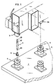
図1は、可動フレームワーク1と、固定式ベース構造体2とを備える、本発明による機器の一実施形態を示す。可動フレームワーク上には、グリップロッド4のグリップ装置3が存在し、かつ固定式ベース構造体上には、この事例ではブロックの形式である汎用アクチュエータ手段6のための安定座弾性装置5が存在する。これらは全て、安定座弾性装置5内にグリップ装置3と垂直に一致して位置決めされたブロック6を順序正しく把持する前の位置にある。ブロック6は、グリップ装置3のうちの1つへ挿入される。
FIG. 1 shows an embodiment of a device according to the invention comprising a
図2は、ブロック6が安定座弾性装置5内に置かれ、かつグリップロッド4が前記ブロック6内に置かれた先行図の機器を示す。ユニットは、可動フレームワーク1上へ位置決めされたグリップ装置3の垂線上に、グリップ装置3がグリップロッド4から分離されて前記可動フレームワーク1の下降を待機している状態で配置されている。
FIG. 2 shows the device of the preceding figure in which the
図3は、可動フレームワーク1が下降してグリップロッド4をグリップ装置3内に嵌め込んだ時点を示している。グリップロッド4自体は、汎用アクチュエータ手段を形成するブロック6内に嵌め込まれる。
FIG. 3 shows a time point when the
図4は、可動フレームワーク1が、この時点では安定座弾性装置5から外されてグリップロッド4内に保持されているブロック6を金型8の自由面7へ対面させている時点の先行図のユニットを示している。金型8は、パネル11の非可視面を形成する二次元的にプレストレスされた補強9および最近に注入された厚いセメントモルタル層10を含む。
FIG. 4 is a preceding view when the
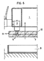
図5は、ブロック6がセメントモルタル層10内へ挿入され、前記セメントモルタル層10が形成されたパネル(11)を金型から剥離できるに足る度合いの硬化に達するまで不動のままである時点の先行図のユニットを示している。
FIG. 5 shows that the
図6は、金型8内に入れられた厚いセメントモルタル層10の硬化後に達成されたパネル11を可動フレームワーク1が剥離している時点の先行図のユニットを示している。
FIG. 6 shows the unit of the preceding figure when the
図7の事例は、図式的に、本機器が高周波電流を用いる硬化加速装置を備える事例に一致している。この装置は、好適には可動フレームワーク1内に組み込まれる上側の金属補強12Aと、下側の金属補強12Bと、高周波電流発生器HFとで構成される。
The example of FIG. 7 corresponds diagrammatically to the example in which the device is equipped with a curing accelerator using high frequency current. This device is preferably composed of an
また、可動フレームワーク1内へ組み込まれる重い上側の金属補強12Aは、高周波吸熱システムにおける上側の補強として作用するが、何れの場合も、パネル11の非可視面を形成するセメントモルタル層10の表面を成形しかつ硬化中のモルタルからの水分蒸発を防止すべく金型8を閉止する働きをする。
Further, the heavy
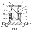
図8および図9は、汎用アクチュエータ手段のうちの1つを安定して支持するための安定座弾性装置5の好適な一実施形態を示している。この事例では、これは具体的に、図10において詳細が分かるような、一方で硬化されるセメントモルタル塊10内に保持するための保持手段13を備えかつ他方でこれと反対側に、グリップロッド4のようなエレメントを扱いかつ/または図示されていない建物構造体へエレメントを固定するためのアンカ手段14を備えるブロック6を指す。
8 and 9 show a preferred embodiment of a stable seat
前記安定座弾性装置5は、固定式ベース構造体2へ固定するためのアンカねじ15Aを装備したベース15と、中央の自動注油ブッシング17およびシール18を装備したガイド本体16とを備え、前記自動注油ブッシング17およびシール18は、環状の蓋19により閉止されてばね22により荷重されるプラットフォーム21のフット20の滑動装置を形成し、プラットフォーム21の内部には、ブロック6を保持するための保持手段13が安定して嵌るリセス24を有する台座プレート23が座している。フット20は軸方向のリセス25を有し、軸方向のリセス25において、プラットフォーム21の浮上および降下の制限をその機能とするエンドストップ26がガイド本体16へ固定式に装着される。
The stable seat
図10および図12は、可動フレームワーク1上へ組み立てられて、この時点で金型から剥離されるに足る程度に硬化されているパネル11上へ垂直の牽引力をかけると思われる類のグリップ装置3を示している。
FIGS. 10 and 12 show a kind of gripping device which is supposed to apply a vertical traction force on the
これらの図においては、可動フレームワーク1上へ設置されたグリップ装置3が上部ガイド本体27および底部ガイド本体28を備え、上部ガイド本体27および底部ガイド本体28は互いに関連づけられて可動フレームワーク1の壁1Aをねじ29によって閉じ込め、両図ではブロック6を把持しているグリップロッド4を包含するための2つの垂直な同心ハウジング30および31を形成することが観察される。
In these drawings, the
上部ガイド本体27は、その側面に、2つの盲ダクト33が垂直ハウジング30の軸に対して横断方向に共平面で開く円筒空胴32を有し、前記円筒空胴32は滑動式円筒本体34により占有され、かつ両盲ダクト33は、共同して前記滑動式円筒本体34の片持ち梁配置で出現しかつ垂直ハウジング30の直径より小さい距離で互いから分離される個々のロッド35により占有される。
The
前記滑動式円筒本体34およびロッド35によって構成されるユニットは、ロッド35を垂直ハウジング30の周囲から分離するに足るスペース内でユニットを軸方向へ移動させるモータ機構36に関連づけられる。
The unit constituted by the sliding
ロッド35が配置される平面は、グリップロッド4の頂端に設けられる溝37に一致し、これにより、前記ロッド35が盲ダクト33内に収容される位置にあるときに前記グリップロッド4をグリップ装置3内に保持することが可能にされ、反対に、前記グリップロッド4は、ロッド35が移動されて前記盲ダクト33内部から部分的に引き出されると解放される。
The plane in which the
モータ機構36は、既知のタイプ、即ち液圧式、空気式または電気式の何れであってもよい。
The
図1、図10および図11は、グリップロッド4が溝37のすぐ先で始まり円錐切頭形となって終わる自由端38を有し、かつ一方で他端に、ブロック6と結合するための、ねじ、バヨネット、磁気またはスナップ式であってもよいカップリング手段39を有することを示している。
1, 10 and 11 show that the
前記図11は、グリップ装置3の底部ガイド本体28と同一である単純な底部ガイド本体40から成るグリップ装置3Aを示しているが、この底部ガイド本体40は、グリップロッド4のグリップ装置3およびグリップ装置3Aの双方における位置合わせを確実にする、可動フレームワーク1へ固定するためのアンカねじを通す複数の穴41と、摩擦、磁気またはばね式であってもよい不図示のグリップロッド4を保持するための位置保持手段42とを装備している。可動フレームワーク1には、金型からパネル11を剥離する際にパネル11を引っ張るに足る限定数のグリップ装置3が設けられるが、一方で、金型剥離を可能にするように作られているグリップ装置3用として意図されていないブロック6を把持するためのグリップ装置3Aは必要な数だけ設けられる。
FIG. 11 shows a
図13は、グリップロッド4により保持されかつ続いて可動フレームワーク1のグリップ装置3により把持されるべく待機している対応するブロック6を安定座弾性装置5内に順序正しく包含するための固定式構造体2の一角を示している。
FIG. 13 shows a fixed type for the sequential inclusion of a
図14は、図2と同様に、かつ図10の詳細を伴って、グリップロッド4がブロック6を捕らえる前にグリップ装置3内に結合されている事例における可動フレームワーク1の位置を示している。
FIG. 14 shows the position of the
Claims (10)
前記セメントモルタル(10)のパネルは、前記パネルを扱いかつ/またはパネルを建物構造体へ固定することに適する汎用アクチュエータ手段(6)を有し、
前記汎用アクチュエータ手段(6)は、セメントモルタル(10)の塊内へその何れの面(11)からも突き出すことなく埋め込まれ、同時に前記汎用アクチュエータ手段(6)は、一方で前記汎用アクチュエータ手段(6)を硬化されるセメントモルタル(10)の塊内へ埋め込むための保持手段(13)を備えかつ他方でこれと反対側にパネルを扱うエレメントおよび前記パネルを前記建物構造体へ固定するエレメントの双方のためのアンカ手段(14)を備え、
前記アンカ位置合わせ機器は、
一方で、[a]同じ複数の汎用アクチュエータ手段(6)を受け入れることに適する複数の安定座弾性装置(5)を水平に支持するための固定式ベース構造体(2)を備え、かつ
他方で、[b]前記安定座弾性装置(5)に一致して、前記汎用アクチュエータ手段(6)を把持するためのグリップ装置(3)を備える可動フレームワーク(1)を備え、かつ
前記グリップ装置(3)と前記汎用アクチュエータ手段(6)とが互いに正確に位置合わせされると、前記グリップ装置(3)は前記汎用アクチュエータ手段(6)を前記固定式ベース構造体(2)に当てて把持し、前記可動フレームワークは前記汎用アクチュエータ手段(6)を前記安定座弾性装置(5)から引き出すことを特徴とするアンカ位置合わせ機器。 Anchor alignment equipment for prefabricated panels of reinforced cement mortar (10) including prestressed biaxial reinforcement (9),
The cement mortar (10) panel comprises universal actuator means (6) suitable for handling the panel and / or securing the panel to a building structure;
The universal actuator means (6) is embedded in the mass of cement mortar (10) without protruding from any surface (11), and at the same time the universal actuator means (6) is on the one hand the universal actuator means ( 6) a holding means (13) for embedding in the mass of cement mortar (10) to be hardened and, on the other hand, an element for handling the panel and an element for fixing the panel to the building structure With anchor means (14) for both,
The anchor alignment device is
On the one hand, [a] a fixed base structure (2) for horizontally supporting a plurality of stable seat elastic devices (5) suitable for receiving the same plurality of general purpose actuator means (6); [B] a movable framework (1) comprising a grip device (3) for gripping the universal actuator means (6) in agreement with the stable seat elastic device (5);
When the grip device (3) and the universal actuator means (6) are accurately aligned with each other , the grip device (3) attaches the universal actuator means (6) to the fixed base structure (2). An anchor alignment device characterized in that the movable framework pulls out the general-purpose actuator means (6) from the stable seat elastic device (5).
前記可動座本体(20、21、23)は、前記固定式ベース本体(15、16)内部で滑動する下側部分および前記固定式ベース本体(15、16)より外部に存在する別の上側部分を有し、
前記上側部分は、弾性プレート(23)のための台座トレイを形成し、
前記弾性プレート(23)は、前記汎用アクチュエータ(6)の前記保持手段(13)を嵌め込むためのリセス(24)を有することを特徴とする、請求項1に記載の補強セメントモルタル(10)のプレハブ式パネルのためのアンカ位置合わせ機器。 The stable seat elastic device (5) comprises a fixed base body (15, 16) and a movable seat body (20, 21, 23) for the universal actuator means (6).
The movable seat body (20, 21, 23) includes a lower part that slides inside the fixed base body (15, 16) and another upper part that exists outside the fixed base body (15, 16). Have
Said upper part forms a pedestal tray for the elastic plate (23);
Said elastic plate (23), the features and Turkey which having a recess (24) for the writing order fitting the holding means (13) of the universal actuator (6), reinforcing cement according to claim 1 Anchor alignment equipment for prefabricated panels of mortar (10).
前記半径方向フィンガ(26)の先端は、前記可動本体(20、21、23)内の短い溝(25)の内側を移動して、前記固定式ベース本体(15、16)と可動本体の前記プラットフォーム(21)との間に位置決めされるばね(22)により荷重された際に、かつ/または前記プラットフォーム(21)へ印加される応力によって前記可動本体(20、21、23)の移動限界を決定することを特徴とする、請求項2に記載の補強セメントモルタル(10)のプレハブ式パネルのためのアンカ位置合わせ機器。 The fixed base body (15, 16) is fixed in the guide bushing (17) for sliding the movable body (20, 21, 23) and a radial finger (26) in a cantilever arrangement. )
The distal ends of the radial fingers (26) move inside the short grooves (25) in the movable body (20, 21, 23), so that the fixed base body (15, 16) and the movable body have the above-mentioned. The movement limit of the movable body (20, 21, 23) is imposed by a stress applied to the platform (21) when loaded by a spring (22) positioned between the platform (21) and / or the platform (21). Anchor alignment device for prefabricated panels of reinforced cement mortar (10) according to claim 2, characterized in that it is determined.
前記グリップ装置内には、一方の端に汎用アクチュエータ手段(6)の一端へ結合するためのカップリング手段(39)を含むと同時にもう一方の端の近くに溝(37)を有するグリップロッド(4)が滑動式に但し時には固定式に収容されることを特徴とする、請求項1に記載の補強セメントモルタル(10)のプレハブ式パネルのためのアンカ位置合わせ機器。 The movable framework (1) has the same number of gripping devices (3) as the stable seat elastic devices (5) of the fixed base structure (2),
The grip device includes a coupling rod (39) for coupling to one end of the universal actuator means (6) at one end and at the same time having a groove (37) near the other end ( Anchor positioning device for prefabricated panels of reinforced cement mortar (10) according to claim 1, characterized in that 4) is accommodated slidingly but sometimes fixedly.
前記金属補強(12A、12B)は、高周波吸熱システムの上側の補強(12A)として作用するのに加えて、パネルの非可視面を形成するセメントモルタル層(10)の表面を成形する働きをし、
前記金属補強(12A、12B)は、硬化中のモルタルからの水分蒸発を防止するために金型(8)を閉止することを特徴とする、請求項9に記載の補強セメントモルタル(10)のプレハブ式パネルのためのアンカ位置合わせ機器。 The movable framework (1) holds heavy metal reinforcement (12A, 12B)
Said metal reinforcement (12A, 12B), in addition to acting as an upper reinforcement of the high-frequency heat absorption system (12A), a cement mortar layer to form a non-visible surface of the panel which serves to form the surface of the (10) And
The reinforced cement mortar (10) according to claim 9, characterized in that the metal reinforcement (12A, 12B) closes the mold (8) to prevent moisture evaporation from the mortar during curing . Anchor alignment equipment for prefabricated panels.
Applications Claiming Priority (1)
| Application Number | Priority Date | Filing Date | Title |
|---|---|---|---|
| PCT/ES2010/000025 WO2011104390A1 (en) | 2010-01-26 | 2010-01-26 | Positioning installation for anchorages in the prefabrication of panels of reinforced cement mortar |
Publications (2)
| Publication Number | Publication Date |
|---|---|
| JP2013520329A JP2013520329A (en) | 2013-06-06 |
| JP5525625B2 true JP5525625B2 (en) | 2014-06-18 |
Family
ID=44506142
Family Applications (1)
| Application Number | Title | Priority Date | Filing Date |
|---|---|---|---|
| JP2012549385A Active JP5525625B2 (en) | 2010-01-26 | 2010-01-26 | Anchor alignment equipment for prefabricated panels of reinforced cement mortar |
Country Status (17)
| Country | Link |
|---|---|
| US (1) | US9038323B2 (en) |
| EP (1) | EP2529908B1 (en) |
| JP (1) | JP5525625B2 (en) |
| KR (1) | KR101668659B1 (en) |
| CN (1) | CN102741026B (en) |
| AU (1) | AU2010346990B2 (en) |
| BR (1) | BR112012017462A2 (en) |
| CA (1) | CA2786342C (en) |
| CU (1) | CU24081B1 (en) |
| DK (1) | DK2529908T3 (en) |
| EG (1) | EG26915A (en) |
| ES (1) | ES2558442T3 (en) |
| MX (1) | MX354429B (en) |
| PL (1) | PL2529908T3 (en) |
| RU (1) | RU2509647C1 (en) |
| SG (1) | SG182645A1 (en) |
| WO (1) | WO2011104390A1 (en) |
Families Citing this family (7)
| Publication number | Priority date | Publication date | Assignee | Title |
|---|---|---|---|---|
| CN104842508B (en) * | 2015-05-25 | 2017-05-31 | 延锋汽车饰件系统(烟台)有限公司 | A kind of gripper for integrating automatic part picking and putting part automatically |
| ES2584073B1 (en) * | 2016-05-26 | 2017-06-29 | Carlos Fradera Pellicer | MANUFACTURING PROCEDURE OF CEMENT MORTAR PANELS PRETENSED WITH A REMOVAL STAGE, AND CORRESPONDING INSTALLATION |
| ES2638830B2 (en) * | 2017-07-08 | 2018-04-12 | Corpus Consulting & Services Sl | MANUFACTURING PROCEDURE OF A MORTAR OR CONCRETE PANEL, USEFUL OF MANUFACTURE OF THE PANEL AND PRODUCT SO OBTAINED |
| FR3075233B1 (en) * | 2017-12-15 | 2020-01-10 | Areva Np | DEVICE AND METHOD FOR ANCHORING EQUIPMENT TO A CIVIL ENGINEERING STRUCTURE |
| US20230109048A1 (en) * | 2020-03-03 | 2023-04-06 | Sapphire Balconies Limited | Method of installing a balcony, and device for the same |
| CN113276269B (en) * | 2021-06-01 | 2022-06-03 | 广东博智林机器人有限公司 | Networking device and assembling method of steel bar net cage |
| CN113290692A (en) * | 2021-07-02 | 2021-08-24 | 中交一公局第二工程有限公司 | Simple tensioning method for prefabricated part steel bar |
Family Cites Families (29)
| Publication number | Priority date | Publication date | Assignee | Title |
|---|---|---|---|---|
| US2772560A (en) * | 1952-06-28 | 1956-12-04 | Herman P Neptune | Pick-up device for pre-cast concrete slabs |
| JPS5339885B2 (en) * | 1974-03-06 | 1978-10-24 | ||
| US4017115A (en) * | 1975-12-17 | 1977-04-12 | The Burke Company | Lift system for concrete slabs |
| US4079983A (en) * | 1977-02-04 | 1978-03-21 | W. C. Dillon And Company, Inc. | Weight lifting eye and socket |
| US4325575A (en) * | 1977-03-28 | 1982-04-20 | The Burke Company | Hoisting coupling for concrete slabs |
| JPS553316A (en) * | 1978-06-19 | 1980-01-11 | Ozawa Concrete Kogyo Kk | Manufacture of concrete product |
| US4290638A (en) * | 1979-10-17 | 1981-09-22 | Superior Concrete Accessories, Inc. | Apparatus for releasable connection to an embedded member |
| DE3037177A1 (en) * | 1980-10-02 | 1982-04-29 | Jürgen 7801 Umkirch Goldberg | DEVICE FOR MAKING A RECESSION IN PRECAST CONCRETE PARTS OR THE LIKE. |
| US4367892A (en) * | 1980-10-23 | 1983-01-11 | The Burke Company | Lift system for tilt-up walls |
| US4437642A (en) * | 1980-10-23 | 1984-03-20 | The Burke Company | Lift system for tilt-up walls |
| DE3224985C2 (en) * | 1982-07-03 | 1984-04-19 | Hochtemperatur-Reaktorbau GmbH, 5000 Köln | Concrete anchor for fastening assembly parts |
| US4512121A (en) * | 1983-05-24 | 1985-04-23 | Roger Carydias | Handling system for precast units |
| SU1196271A1 (en) * | 1984-06-26 | 1985-12-07 | Всесоюзный научно-исследовательский и проектный институт титана | Device for fixing sunk slinging loop in moulding reinforced concrete articles |
| US4676035A (en) * | 1986-03-27 | 1987-06-30 | Home Crafts Corporation | Reinforced concrete panels with improved welded joint |
| DE3714581C2 (en) * | 1987-04-30 | 1995-04-27 | Hugo Bittlmayer | Device for the correct arrangement of prefabricated reinforcements in reinforced concrete element slabs |
| US5226265A (en) * | 1989-03-22 | 1993-07-13 | The Burke Company | Apparatus and method for lifting tilt-up wall constructions |
| JPH0672480B2 (en) * | 1989-04-17 | 1994-09-14 | 株式会社イナックス | Tile pasting device to panel |
| FR2671119B1 (en) * | 1990-12-28 | 1993-04-09 | Saret France | CONCRETE CONSTRUCTION ELEMENTS, PRE-STRESSED, OF THE PRELABS TYPE, INSTALLATION AND METHOD FOR THEIR MANUFACTURE. |
| JPH0716408Y2 (en) * | 1992-04-08 | 1995-04-19 | 大和ハウス工業株式会社 | Panel tiler |
| IT1284894B1 (en) * | 1996-09-30 | 1998-05-28 | Sergio Zambelli | DEVICE FOR LIFTING PREFABRICATED PRODUCTS IN PARTICULAR CONCRETE OR SIMILAR |
| AUPP330498A0 (en) * | 1998-05-04 | 1998-05-28 | Paterson, Ian Alexander | Improvements relating to the lifting of precast bodies such as concrete panels |
| IT1319375B1 (en) * | 2000-12-11 | 2003-10-10 | Sergio Zambelli | LIFTING INSERT FOR PREFABRICATED CEMENTITIOUS MANUFACTURED COATINGS TO INCREASE THE CUT RESISTANCE |
| IT1319705B1 (en) * | 2000-12-21 | 2003-11-03 | Sergio Zambelli | PROTECTION DEVICE FOR TUBULAR BODY LIFTING INSERTS, WHILE SWITCHING THEM INSIDE A PREFABRICATED MANUFACTURE |
| WO2004020761A1 (en) * | 2002-08-28 | 2004-03-11 | Pellicer Carlos F | Method of producing a light façade panel for construction, means for the production and installation of same, the light façade panel thus obtained and use thereof |
| ES1057874Y (en) * | 2004-06-18 | 2005-01-16 | Pellicer Carlos F | ASIDOR HEAD |
| US7677829B2 (en) * | 2005-10-20 | 2010-03-16 | Poly-Tec Products, Inc. | Inserts and reusable holder therefor |
| ES1065420Y (en) * | 2007-05-14 | 2007-11-16 | Pellicer Carlos F | MORTAR PANEL WITH PRETENSED BIAXIAL ARMOR |
| WO2008139003A1 (en) * | 2007-05-14 | 2008-11-20 | Pellicer Carlos F | Cement mortar panel with pretensed biaxial reinforcement |
| AU2009307053B2 (en) * | 2008-10-23 | 2015-11-26 | Obelix Holdings Pty Limited | A lifting device and method for concrete elements |
-
2010
- 2010-01-26 RU RU2012136440/03A patent/RU2509647C1/en not_active IP Right Cessation
- 2010-01-26 MX MX2012008707A patent/MX354429B/en active IP Right Grant
- 2010-01-26 JP JP2012549385A patent/JP5525625B2/en active Active
- 2010-01-26 EP EP10846389.4A patent/EP2529908B1/en not_active Not-in-force
- 2010-01-26 ES ES10846389.4T patent/ES2558442T3/en active Active
- 2010-01-26 AU AU2010346990A patent/AU2010346990B2/en not_active Ceased
- 2010-01-26 PL PL10846389T patent/PL2529908T3/en unknown
- 2010-01-26 CA CA2786342A patent/CA2786342C/en not_active Expired - Fee Related
- 2010-01-26 DK DK10846389.4T patent/DK2529908T3/en active
- 2010-01-26 SG SG2012053922A patent/SG182645A1/en unknown
- 2010-01-26 KR KR1020127020924A patent/KR101668659B1/en active IP Right Grant
- 2010-01-26 CN CN201080062409.6A patent/CN102741026B/en not_active Expired - Fee Related
- 2010-01-26 US US13/521,330 patent/US9038323B2/en not_active Expired - Fee Related
- 2010-01-26 BR BR112012017462A patent/BR112012017462A2/en not_active IP Right Cessation
- 2010-01-26 WO PCT/ES2010/000025 patent/WO2011104390A1/en active Application Filing
- 2010-01-26 CU CU2012000105A patent/CU24081B1/en active IP Right Grant
-
2012
- 2012-07-08 EG EG2012071224A patent/EG26915A/en active
Also Published As
| Publication number | Publication date |
|---|---|
| RU2509647C1 (en) | 2014-03-20 |
| CA2786342A1 (en) | 2011-09-01 |
| EP2529908A4 (en) | 2013-11-06 |
| EP2529908B1 (en) | 2015-12-02 |
| MX354429B (en) | 2018-03-05 |
| BR112012017462A2 (en) | 2016-04-19 |
| SG182645A1 (en) | 2012-08-30 |
| MX2012008707A (en) | 2012-08-23 |
| US9038323B2 (en) | 2015-05-26 |
| CA2786342C (en) | 2016-11-01 |
| EG26915A (en) | 2014-12-21 |
| CN102741026A (en) | 2012-10-17 |
| EP2529908A1 (en) | 2012-12-05 |
| KR101668659B1 (en) | 2016-10-24 |
| CN102741026B (en) | 2015-10-07 |
| RU2012136440A (en) | 2014-03-10 |
| DK2529908T3 (en) | 2016-02-08 |
| PL2529908T3 (en) | 2016-04-29 |
| CU24081B1 (en) | 2015-03-30 |
| AU2010346990B2 (en) | 2014-06-19 |
| WO2011104390A8 (en) | 2012-06-21 |
| JP2013520329A (en) | 2013-06-06 |
| US20120285006A1 (en) | 2012-11-15 |
| KR20120117854A (en) | 2012-10-24 |
| CU20120105A7 (en) | 2012-11-15 |
| WO2011104390A1 (en) | 2011-09-01 |
| ES2558442T3 (en) | 2016-02-04 |
| AU2010346990A1 (en) | 2012-08-23 |
Similar Documents
| Publication | Publication Date | Title |
|---|---|---|
| JP5525625B2 (en) | Anchor alignment equipment for prefabricated panels of reinforced cement mortar | |
| AU626137B2 (en) | Apparatus and method for lifting tilt-up wall constructions | |
| KR20130132694A (en) | Improved fixating component for a fixture | |
| WO2013040064A3 (en) | Device for forming post sleeves, and method of use | |
| US4998705A (en) | Apparatus for forming voids in concrete | |
| KR101682211B1 (en) | Bottom frameform panel supporting apparatus by which bottom frameform is early detatchable | |
| CN213764743U (en) | A high-efficient assembly device of pincers handle gum cover for tiger pliers | |
| KR101524216B1 (en) | Electric wiring box | |
| KR101493249B1 (en) | Insert for concrete slab | |
| KR200444420Y1 (en) | The reclaimable anchorage for aluminum form panel cross member | |
| JP4058702B1 (en) | Insulation foundation | |
| CN219311567U (en) | Combined template for prefabricated component | |
| CN114179216B (en) | Production process of assembled bathroom roof | |
| CA2740756C (en) | Method and apparatus for positioning a conduit guide in a moldable material prior to pouring the material into a form | |
| CN218622563U (en) | Assembled building supporting seat | |
| KR20180076402A (en) | Hitting device for slab form fixing pin | |
| JP3665305B2 (en) | Manufacturing method of assembly parts | |
| CN210525420U (en) | Wall slot pre-embedding device | |
| CN211054000U (en) | Be used for fashioned flange mould of precast concrete component | |
| KR101394457B1 (en) | One Touch Assembling and Separating Type Device For Preventing Buoyance In Hollow Core Slab | |
| ES2346944A1 (en) | Positioning installation of anchors in the prefabrication of panels of armed cement mortar (Machine-translation by Google Translate, not legally binding) | |
| CN202187554U (en) | Floor preset hole mould for wooden bottom die | |
| KR20110007984U (en) | The suspension for gypsum board fixing | |
| CA1335476C (en) | Apparatus and method for lifting tilt-up wall constructions | |
| JPH0342198Y2 (en) |
Legal Events
| Date | Code | Title | Description |
|---|---|---|---|
| A977 | Report on retrieval |
Free format text: JAPANESE INTERMEDIATE CODE: A971007 Effective date: 20130924 |
|
| A131 | Notification of reasons for refusal |
Free format text: JAPANESE INTERMEDIATE CODE: A131 Effective date: 20131001 |
|
| A521 | Written amendment |
Free format text: JAPANESE INTERMEDIATE CODE: A523 Effective date: 20131227 |
|
| TRDD | Decision of grant or rejection written | ||
| A01 | Written decision to grant a patent or to grant a registration (utility model) |
Free format text: JAPANESE INTERMEDIATE CODE: A01 Effective date: 20140318 |
|
| A61 | First payment of annual fees (during grant procedure) |
Free format text: JAPANESE INTERMEDIATE CODE: A61 Effective date: 20140411 |
|
| R150 | Certificate of patent or registration of utility model |
Ref document number: 5525625 Country of ref document: JP Free format text: JAPANESE INTERMEDIATE CODE: R150 |
|
| R250 | Receipt of annual fees |
Free format text: JAPANESE INTERMEDIATE CODE: R250 |
|
| R250 | Receipt of annual fees |
Free format text: JAPANESE INTERMEDIATE CODE: R250 |
|
| R250 | Receipt of annual fees |
Free format text: JAPANESE INTERMEDIATE CODE: R250 |
|
| R250 | Receipt of annual fees |
Free format text: JAPANESE INTERMEDIATE CODE: R250 |