JP5524924B2 - Honeycomb structure - Google Patents
Honeycomb structure Download PDFInfo
- Publication number
- JP5524924B2 JP5524924B2 JP2011209119A JP2011209119A JP5524924B2 JP 5524924 B2 JP5524924 B2 JP 5524924B2 JP 2011209119 A JP2011209119 A JP 2011209119A JP 2011209119 A JP2011209119 A JP 2011209119A JP 5524924 B2 JP5524924 B2 JP 5524924B2
- Authority
- JP
- Japan
- Prior art keywords
- honeycomb
- coating material
- honeycomb structure
- bonding
- filler
- Prior art date
- Legal status (The legal status is an assumption and is not a legal conclusion. Google has not performed a legal analysis and makes no representation as to the accuracy of the status listed.)
- Expired - Fee Related
Links
Images

Classifications
-
- F—MECHANICAL ENGINEERING; LIGHTING; HEATING; WEAPONS; BLASTING
- F01—MACHINES OR ENGINES IN GENERAL; ENGINE PLANTS IN GENERAL; STEAM ENGINES
- F01N—GAS-FLOW SILENCERS OR EXHAUST APPARATUS FOR MACHINES OR ENGINES IN GENERAL; GAS-FLOW SILENCERS OR EXHAUST APPARATUS FOR INTERNAL-COMBUSTION ENGINES
- F01N3/00—Exhaust or silencing apparatus having means for purifying, rendering innocuous, or otherwise treating exhaust
- F01N3/02—Exhaust or silencing apparatus having means for purifying, rendering innocuous, or otherwise treating exhaust for cooling, or for removing solid constituents of, exhaust
- F01N3/021—Exhaust or silencing apparatus having means for purifying, rendering innocuous, or otherwise treating exhaust for cooling, or for removing solid constituents of, exhaust by means of filters
- F01N3/022—Exhaust or silencing apparatus having means for purifying, rendering innocuous, or otherwise treating exhaust for cooling, or for removing solid constituents of, exhaust by means of filters characterised by specially adapted filtering structure, e.g. honeycomb, mesh or fibrous
- F01N3/0222—Exhaust or silencing apparatus having means for purifying, rendering innocuous, or otherwise treating exhaust for cooling, or for removing solid constituents of, exhaust by means of filters characterised by specially adapted filtering structure, e.g. honeycomb, mesh or fibrous the structure being monolithic, e.g. honeycombs
-
- B—PERFORMING OPERATIONS; TRANSPORTING
- B01—PHYSICAL OR CHEMICAL PROCESSES OR APPARATUS IN GENERAL
- B01D—SEPARATION
- B01D39/00—Filtering material for liquid or gaseous fluids
-
- B—PERFORMING OPERATIONS; TRANSPORTING
- B01—PHYSICAL OR CHEMICAL PROCESSES OR APPARATUS IN GENERAL
- B01D—SEPARATION
- B01D53/00—Separation of gases or vapours; Recovering vapours of volatile solvents from gases; Chemical or biological purification of waste gases, e.g. engine exhaust gases, smoke, fumes, flue gases, aerosols
- B01D53/34—Chemical or biological purification of waste gases
-
- C—CHEMISTRY; METALLURGY
- C04—CEMENTS; CONCRETE; ARTIFICIAL STONE; CERAMICS; REFRACTORIES
- C04B—LIME, MAGNESIA; SLAG; CEMENTS; COMPOSITIONS THEREOF, e.g. MORTARS, CONCRETE OR LIKE BUILDING MATERIALS; ARTIFICIAL STONE; CERAMICS; REFRACTORIES; TREATMENT OF NATURAL STONE
- C04B35/00—Shaped ceramic products characterised by their composition; Ceramics compositions; Processing powders of inorganic compounds preparatory to the manufacturing of ceramic products
- C04B35/515—Shaped ceramic products characterised by their composition; Ceramics compositions; Processing powders of inorganic compounds preparatory to the manufacturing of ceramic products based on non-oxide ceramics
- C04B35/56—Shaped ceramic products characterised by their composition; Ceramics compositions; Processing powders of inorganic compounds preparatory to the manufacturing of ceramic products based on non-oxide ceramics based on carbides or oxycarbides
- C04B35/565—Shaped ceramic products characterised by their composition; Ceramics compositions; Processing powders of inorganic compounds preparatory to the manufacturing of ceramic products based on non-oxide ceramics based on carbides or oxycarbides based on silicon carbide
-
- C—CHEMISTRY; METALLURGY
- C04—CEMENTS; CONCRETE; ARTIFICIAL STONE; CERAMICS; REFRACTORIES
- C04B—LIME, MAGNESIA; SLAG; CEMENTS; COMPOSITIONS THEREOF, e.g. MORTARS, CONCRETE OR LIKE BUILDING MATERIALS; ARTIFICIAL STONE; CERAMICS; REFRACTORIES; TREATMENT OF NATURAL STONE
- C04B35/00—Shaped ceramic products characterised by their composition; Ceramics compositions; Processing powders of inorganic compounds preparatory to the manufacturing of ceramic products
- C04B35/622—Forming processes; Processing powders of inorganic compounds preparatory to the manufacturing of ceramic products
- C04B35/626—Preparing or treating the powders individually or as batches ; preparing or treating macroscopic reinforcing agents for ceramic products, e.g. fibres; mechanical aspects section B
- C04B35/62605—Treating the starting powders individually or as mixtures
- C04B35/62625—Wet mixtures
- C04B35/6263—Wet mixtures characterised by their solids loadings, i.e. the percentage of solids
-
- C—CHEMISTRY; METALLURGY
- C04—CEMENTS; CONCRETE; ARTIFICIAL STONE; CERAMICS; REFRACTORIES
- C04B—LIME, MAGNESIA; SLAG; CEMENTS; COMPOSITIONS THEREOF, e.g. MORTARS, CONCRETE OR LIKE BUILDING MATERIALS; ARTIFICIAL STONE; CERAMICS; REFRACTORIES; TREATMENT OF NATURAL STONE
- C04B35/00—Shaped ceramic products characterised by their composition; Ceramics compositions; Processing powders of inorganic compounds preparatory to the manufacturing of ceramic products
- C04B35/622—Forming processes; Processing powders of inorganic compounds preparatory to the manufacturing of ceramic products
- C04B35/626—Preparing or treating the powders individually or as batches ; preparing or treating macroscopic reinforcing agents for ceramic products, e.g. fibres; mechanical aspects section B
- C04B35/62605—Treating the starting powders individually or as mixtures
- C04B35/62645—Thermal treatment of powders or mixtures thereof other than sintering
- C04B35/62655—Drying, e.g. freeze-drying, spray-drying, microwave or supercritical drying
-
- C—CHEMISTRY; METALLURGY
- C04—CEMENTS; CONCRETE; ARTIFICIAL STONE; CERAMICS; REFRACTORIES
- C04B—LIME, MAGNESIA; SLAG; CEMENTS; COMPOSITIONS THEREOF, e.g. MORTARS, CONCRETE OR LIKE BUILDING MATERIALS; ARTIFICIAL STONE; CERAMICS; REFRACTORIES; TREATMENT OF NATURAL STONE
- C04B35/00—Shaped ceramic products characterised by their composition; Ceramics compositions; Processing powders of inorganic compounds preparatory to the manufacturing of ceramic products
- C04B35/622—Forming processes; Processing powders of inorganic compounds preparatory to the manufacturing of ceramic products
- C04B35/626—Preparing or treating the powders individually or as batches ; preparing or treating macroscopic reinforcing agents for ceramic products, e.g. fibres; mechanical aspects section B
- C04B35/63—Preparing or treating the powders individually or as batches ; preparing or treating macroscopic reinforcing agents for ceramic products, e.g. fibres; mechanical aspects section B using additives specially adapted for forming the products, e.g.. binder binders
- C04B35/6303—Inorganic additives
- C04B35/6316—Binders based on silicon compounds
-
- C—CHEMISTRY; METALLURGY
- C04—CEMENTS; CONCRETE; ARTIFICIAL STONE; CERAMICS; REFRACTORIES
- C04B—LIME, MAGNESIA; SLAG; CEMENTS; COMPOSITIONS THEREOF, e.g. MORTARS, CONCRETE OR LIKE BUILDING MATERIALS; ARTIFICIAL STONE; CERAMICS; REFRACTORIES; TREATMENT OF NATURAL STONE
- C04B35/00—Shaped ceramic products characterised by their composition; Ceramics compositions; Processing powders of inorganic compounds preparatory to the manufacturing of ceramic products
- C04B35/71—Ceramic products containing macroscopic reinforcing agents
- C04B35/78—Ceramic products containing macroscopic reinforcing agents containing non-metallic materials
- C04B35/80—Fibres, filaments, whiskers, platelets, or the like
-
- C—CHEMISTRY; METALLURGY
- C04—CEMENTS; CONCRETE; ARTIFICIAL STONE; CERAMICS; REFRACTORIES
- C04B—LIME, MAGNESIA; SLAG; CEMENTS; COMPOSITIONS THEREOF, e.g. MORTARS, CONCRETE OR LIKE BUILDING MATERIALS; ARTIFICIAL STONE; CERAMICS; REFRACTORIES; TREATMENT OF NATURAL STONE
- C04B37/00—Joining burned ceramic articles with other burned ceramic articles or other articles by heating
- C04B37/003—Joining burned ceramic articles with other burned ceramic articles or other articles by heating by means of an interlayer consisting of a combination of materials selected from glass, or ceramic material with metals, metal oxides or metal salts
- C04B37/005—Joining burned ceramic articles with other burned ceramic articles or other articles by heating by means of an interlayer consisting of a combination of materials selected from glass, or ceramic material with metals, metal oxides or metal salts consisting of glass or ceramic material
-
- C—CHEMISTRY; METALLURGY
- C04—CEMENTS; CONCRETE; ARTIFICIAL STONE; CERAMICS; REFRACTORIES
- C04B—LIME, MAGNESIA; SLAG; CEMENTS; COMPOSITIONS THEREOF, e.g. MORTARS, CONCRETE OR LIKE BUILDING MATERIALS; ARTIFICIAL STONE; CERAMICS; REFRACTORIES; TREATMENT OF NATURAL STONE
- C04B38/00—Porous mortars, concrete, artificial stone or ceramic ware; Preparation thereof
- C04B38/0006—Honeycomb structures
- C04B38/0016—Honeycomb structures assembled from subunits
- C04B38/0019—Honeycomb structures assembled from subunits characterised by the material used for joining separate subunits
-
- B—PERFORMING OPERATIONS; TRANSPORTING
- B32—LAYERED PRODUCTS
- B32B—LAYERED PRODUCTS, i.e. PRODUCTS BUILT-UP OF STRATA OF FLAT OR NON-FLAT, e.g. CELLULAR OR HONEYCOMB, FORM
- B32B2315/00—Other materials containing non-metallic inorganic compounds not provided for in groups B32B2311/00 - B32B2313/04
- B32B2315/02—Ceramics
-
- C—CHEMISTRY; METALLURGY
- C04—CEMENTS; CONCRETE; ARTIFICIAL STONE; CERAMICS; REFRACTORIES
- C04B—LIME, MAGNESIA; SLAG; CEMENTS; COMPOSITIONS THEREOF, e.g. MORTARS, CONCRETE OR LIKE BUILDING MATERIALS; ARTIFICIAL STONE; CERAMICS; REFRACTORIES; TREATMENT OF NATURAL STONE
- C04B2111/00—Mortars, concrete or artificial stone or mixtures to prepare them, characterised by specific function, property or use
- C04B2111/00474—Uses not provided for elsewhere in C04B2111/00
- C04B2111/00793—Uses not provided for elsewhere in C04B2111/00 as filters or diaphragms
-
- C—CHEMISTRY; METALLURGY
- C04—CEMENTS; CONCRETE; ARTIFICIAL STONE; CERAMICS; REFRACTORIES
- C04B—LIME, MAGNESIA; SLAG; CEMENTS; COMPOSITIONS THEREOF, e.g. MORTARS, CONCRETE OR LIKE BUILDING MATERIALS; ARTIFICIAL STONE; CERAMICS; REFRACTORIES; TREATMENT OF NATURAL STONE
- C04B2235/00—Aspects relating to ceramic starting mixtures or sintered ceramic products
- C04B2235/02—Composition of constituents of the starting material or of secondary phases of the final product
- C04B2235/30—Constituents and secondary phases not being of a fibrous nature
- C04B2235/34—Non-metal oxides, non-metal mixed oxides, or salts thereof that form the non-metal oxides upon heating, e.g. carbonates, nitrates, (oxy)hydroxides, chlorides
- C04B2235/3418—Silicon oxide, silicic acids or oxide forming salts thereof, e.g. silica sol, fused silica, silica fume, cristobalite, quartz or flint
-
- C—CHEMISTRY; METALLURGY
- C04—CEMENTS; CONCRETE; ARTIFICIAL STONE; CERAMICS; REFRACTORIES
- C04B—LIME, MAGNESIA; SLAG; CEMENTS; COMPOSITIONS THEREOF, e.g. MORTARS, CONCRETE OR LIKE BUILDING MATERIALS; ARTIFICIAL STONE; CERAMICS; REFRACTORIES; TREATMENT OF NATURAL STONE
- C04B2235/00—Aspects relating to ceramic starting mixtures or sintered ceramic products
- C04B2235/02—Composition of constituents of the starting material or of secondary phases of the final product
- C04B2235/30—Constituents and secondary phases not being of a fibrous nature
- C04B2235/34—Non-metal oxides, non-metal mixed oxides, or salts thereof that form the non-metal oxides upon heating, e.g. carbonates, nitrates, (oxy)hydroxides, chlorides
- C04B2235/349—Clays, e.g. bentonites, smectites such as montmorillonite, vermiculites or kaolines, e.g. illite, talc or sepiolite
-
- C—CHEMISTRY; METALLURGY
- C04—CEMENTS; CONCRETE; ARTIFICIAL STONE; CERAMICS; REFRACTORIES
- C04B—LIME, MAGNESIA; SLAG; CEMENTS; COMPOSITIONS THEREOF, e.g. MORTARS, CONCRETE OR LIKE BUILDING MATERIALS; ARTIFICIAL STONE; CERAMICS; REFRACTORIES; TREATMENT OF NATURAL STONE
- C04B2235/00—Aspects relating to ceramic starting mixtures or sintered ceramic products
- C04B2235/02—Composition of constituents of the starting material or of secondary phases of the final product
- C04B2235/30—Constituents and secondary phases not being of a fibrous nature
- C04B2235/42—Non metallic elements added as constituents or additives, e.g. sulfur, phosphor, selenium or tellurium
- C04B2235/428—Silicon
-
- C—CHEMISTRY; METALLURGY
- C04—CEMENTS; CONCRETE; ARTIFICIAL STONE; CERAMICS; REFRACTORIES
- C04B—LIME, MAGNESIA; SLAG; CEMENTS; COMPOSITIONS THEREOF, e.g. MORTARS, CONCRETE OR LIKE BUILDING MATERIALS; ARTIFICIAL STONE; CERAMICS; REFRACTORIES; TREATMENT OF NATURAL STONE
- C04B2235/00—Aspects relating to ceramic starting mixtures or sintered ceramic products
- C04B2235/02—Composition of constituents of the starting material or of secondary phases of the final product
- C04B2235/50—Constituents or additives of the starting mixture chosen for their shape or used because of their shape or their physical appearance
- C04B2235/52—Constituents or additives characterised by their shapes
- C04B2235/5208—Fibers
- C04B2235/5216—Inorganic
- C04B2235/522—Oxidic
- C04B2235/5228—Silica and alumina, including aluminosilicates, e.g. mullite
-
- C—CHEMISTRY; METALLURGY
- C04—CEMENTS; CONCRETE; ARTIFICIAL STONE; CERAMICS; REFRACTORIES
- C04B—LIME, MAGNESIA; SLAG; CEMENTS; COMPOSITIONS THEREOF, e.g. MORTARS, CONCRETE OR LIKE BUILDING MATERIALS; ARTIFICIAL STONE; CERAMICS; REFRACTORIES; TREATMENT OF NATURAL STONE
- C04B2235/00—Aspects relating to ceramic starting mixtures or sintered ceramic products
- C04B2235/70—Aspects relating to sintered or melt-casted ceramic products
- C04B2235/74—Physical characteristics
- C04B2235/77—Density
-
- C—CHEMISTRY; METALLURGY
- C04—CEMENTS; CONCRETE; ARTIFICIAL STONE; CERAMICS; REFRACTORIES
- C04B—LIME, MAGNESIA; SLAG; CEMENTS; COMPOSITIONS THEREOF, e.g. MORTARS, CONCRETE OR LIKE BUILDING MATERIALS; ARTIFICIAL STONE; CERAMICS; REFRACTORIES; TREATMENT OF NATURAL STONE
- C04B2235/00—Aspects relating to ceramic starting mixtures or sintered ceramic products
- C04B2235/70—Aspects relating to sintered or melt-casted ceramic products
- C04B2235/80—Phases present in the sintered or melt-cast ceramic products other than the main phase
-
- C—CHEMISTRY; METALLURGY
- C04—CEMENTS; CONCRETE; ARTIFICIAL STONE; CERAMICS; REFRACTORIES
- C04B—LIME, MAGNESIA; SLAG; CEMENTS; COMPOSITIONS THEREOF, e.g. MORTARS, CONCRETE OR LIKE BUILDING MATERIALS; ARTIFICIAL STONE; CERAMICS; REFRACTORIES; TREATMENT OF NATURAL STONE
- C04B2235/00—Aspects relating to ceramic starting mixtures or sintered ceramic products
- C04B2235/70—Aspects relating to sintered or melt-casted ceramic products
- C04B2235/96—Properties of ceramic products, e.g. mechanical properties such as strength, toughness, wear resistance
-
- C—CHEMISTRY; METALLURGY
- C04—CEMENTS; CONCRETE; ARTIFICIAL STONE; CERAMICS; REFRACTORIES
- C04B—LIME, MAGNESIA; SLAG; CEMENTS; COMPOSITIONS THEREOF, e.g. MORTARS, CONCRETE OR LIKE BUILDING MATERIALS; ARTIFICIAL STONE; CERAMICS; REFRACTORIES; TREATMENT OF NATURAL STONE
- C04B2237/00—Aspects relating to ceramic laminates or to joining of ceramic articles with other articles by heating
- C04B2237/02—Aspects relating to interlayers, e.g. used to join ceramic articles with other articles by heating
- C04B2237/04—Ceramic interlayers
- C04B2237/08—Non-oxidic interlayers
- C04B2237/083—Carbide interlayers, e.g. silicon carbide interlayers
-
- C—CHEMISTRY; METALLURGY
- C04—CEMENTS; CONCRETE; ARTIFICIAL STONE; CERAMICS; REFRACTORIES
- C04B—LIME, MAGNESIA; SLAG; CEMENTS; COMPOSITIONS THEREOF, e.g. MORTARS, CONCRETE OR LIKE BUILDING MATERIALS; ARTIFICIAL STONE; CERAMICS; REFRACTORIES; TREATMENT OF NATURAL STONE
- C04B2237/00—Aspects relating to ceramic laminates or to joining of ceramic articles with other articles by heating
- C04B2237/30—Composition of layers of ceramic laminates or of ceramic or metallic articles to be joined by heating, e.g. Si substrates
- C04B2237/32—Ceramic
- C04B2237/36—Non-oxidic
- C04B2237/365—Silicon carbide
-
- Y—GENERAL TAGGING OF NEW TECHNOLOGICAL DEVELOPMENTS; GENERAL TAGGING OF CROSS-SECTIONAL TECHNOLOGIES SPANNING OVER SEVERAL SECTIONS OF THE IPC; TECHNICAL SUBJECTS COVERED BY FORMER USPC CROSS-REFERENCE ART COLLECTIONS [XRACs] AND DIGESTS
- Y02—TECHNOLOGIES OR APPLICATIONS FOR MITIGATION OR ADAPTATION AGAINST CLIMATE CHANGE
- Y02T—CLIMATE CHANGE MITIGATION TECHNOLOGIES RELATED TO TRANSPORTATION
- Y02T10/00—Road transport of goods or passengers
- Y02T10/10—Internal combustion engine [ICE] based vehicles
- Y02T10/12—Improving ICE efficiencies
-
- Y—GENERAL TAGGING OF NEW TECHNOLOGICAL DEVELOPMENTS; GENERAL TAGGING OF CROSS-SECTIONAL TECHNOLOGIES SPANNING OVER SEVERAL SECTIONS OF THE IPC; TECHNICAL SUBJECTS COVERED BY FORMER USPC CROSS-REFERENCE ART COLLECTIONS [XRACs] AND DIGESTS
- Y10—TECHNICAL SUBJECTS COVERED BY FORMER USPC
- Y10S—TECHNICAL SUBJECTS COVERED BY FORMER USPC CROSS-REFERENCE ART COLLECTIONS [XRACs] AND DIGESTS
- Y10S55/00—Gas separation
- Y10S55/30—Exhaust treatment
Landscapes
- Chemical & Material Sciences (AREA)
- Engineering & Computer Science (AREA)
- Ceramic Engineering (AREA)
- Manufacturing & Machinery (AREA)
- Structural Engineering (AREA)
- Organic Chemistry (AREA)
- Materials Engineering (AREA)
- Inorganic Chemistry (AREA)
- Chemical Kinetics & Catalysis (AREA)
- Thermal Sciences (AREA)
- General Engineering & Computer Science (AREA)
- Physics & Mathematics (AREA)
- Mechanical Engineering (AREA)
- Combustion & Propulsion (AREA)
- Environmental & Geological Engineering (AREA)
- Biomedical Technology (AREA)
- Health & Medical Sciences (AREA)
- Analytical Chemistry (AREA)
- General Chemical & Material Sciences (AREA)
- Oil, Petroleum & Natural Gas (AREA)
- Filtering Materials (AREA)
- Ceramic Products (AREA)
- Filtering Of Dispersed Particles In Gases (AREA)
- Processes For Solid Components From Exhaust (AREA)
Description
本発明は、ハニカムセグメントの複数が接合材によって一体的に接合されたハニカム構造体に関する。さらに詳しくは、排ガス中の粒子状物質(パティキュレート)等を捕集するフィルタとして特に有用な、コーティング材による被覆後における小孔やクラック等の欠陥の発生が確実に抑制された、耐久性に優れたハニカム構造体に関する。 The present invention relates to a honeycomb structure in which a plurality of honeycomb segments are integrally bonded by a bonding material. More specifically, it is particularly useful as a filter that collects particulate matter (particulates) etc. in exhaust gas, and the occurrence of defects such as small holes and cracks after coating with a coating material is reliably suppressed, and durability is improved. The present invention relates to an excellent honeycomb structure.
排ガス用の捕集フィルタとして、例えば、ディーゼルエンジン等からの排ガスに含まれている粒子状物質(パティキュレート)を捕捉して除去するために、ディーゼルパティキュレートフィルタ(DPF)が、ディーゼルエンジンの排気系等に組み込まれて用いられている。このようなDPFを初めとする排ガス用の捕集フィルタは、ハニカムセグメントの複数が接合材によって一体的に接合されたハニカム構造体から構成されている。 As a collection filter for exhaust gas, for example, in order to capture and remove particulate matter (particulate) contained in exhaust gas from a diesel engine or the like, a diesel particulate filter (DPF) is used for exhaust of a diesel engine. It is used by being incorporated into the system. Such a collection filter for exhaust gas such as DPF is composed of a honeycomb structure in which a plurality of honeycomb segments are integrally bonded by a bonding material.
このようなハニカム構造体は、例えば、炭化珪素等からなる多孔質の隔壁によって区画、形成された流体の流路となる複数のセルが中心軸方向に互いに並行するように配設された構造を有し、それぞれが全体構造の一部を構成する形状を有するとともに、中心軸に対して垂直な方向に組み付けられることによって全体構造を構成することになる形状を有する複数のハニカムセグメントが、接合材によって一体的に接合されて、中心軸に対して垂直な平面で切断した全体の断面形状が円形等の所定の形状となるように成形された後、その外周面がコーティング材により被覆された構造となっている。隣接したセルの端部は、交互に目封じされている。すなわち、一のセルは、一方の端部が開口し、他方の端部が目封じされており、これと隣接する他のセルは一方の端部が目封じされ、他方の端部が開口している。 Such a honeycomb structure has a structure in which, for example, a plurality of cells that are partitioned and formed by porous partition walls made of silicon carbide or the like are arranged in parallel to each other in the central axis direction. A plurality of honeycomb segments each having a shape that constitutes a part of the overall structure and a shape that constitutes the overall structure by being assembled in a direction perpendicular to the central axis. A structure in which the outer peripheral surface is coated with a coating material after being integrally joined by the shape and formed so that the entire cross-sectional shape cut by a plane perpendicular to the central axis becomes a predetermined shape such as a circle. It has become. The ends of adjacent cells are alternately sealed. That is, one end of one cell is open at the other end and the other end is sealed, and another cell adjacent thereto is sealed at one end and the other end is open. ing.
このような構造とすることにより、一方の端部から所定のセル(流入セル)に流入させた排ガスを、多孔質の隔壁を通過させることによって流入セルに隣接したセル(流出セル)を経由して流出させ、隔壁を通過させる際に排ガス中の粒子状物質(パティキュレート)を隔壁に捕捉させることによって、排ガスの浄化をすることができる。 By adopting such a structure, the exhaust gas flowing into a predetermined cell (inflow cell) from one end is passed through a cell (outflow cell) adjacent to the inflow cell by passing through a porous partition wall. When the particulate matter (particulates) in the exhaust gas is captured by the partition wall when it is allowed to flow out and pass through the partition wall, the exhaust gas can be purified.
このようなハニカム構造体に用いられる、複数のハニカムセグメントを一体的に接合するための接合材及びその外周面を被覆するためのコーティング材に対しては、良好な塗布性が要求される。特に、接合材においては、ハニカムセグメントの圧着時に良好な延び性をも要求される。これらの特性を得るためには、塗布時の接合材及びコーティング材の粘度を下げることが有効な手段であるが、低粘度の接合材及びコーティング材においては、用いる溶媒量が多くなるため、乾燥時における脱溶媒収縮量が大きくなる。このため、接合材による接合後において、接合部剥れやクラック等の欠陥が発生し易く、またコーティング材による被覆後において、小孔、クラック、擦れ等の欠陥が発生し易いという問題があった。 Good applicability is required for a bonding material for integrally bonding a plurality of honeycomb segments and a coating material for covering the outer peripheral surface used in such a honeycomb structure. In particular, the bonding material is required to have good stretchability when the honeycomb segments are pressed. In order to obtain these characteristics, it is an effective means to reduce the viscosity of the bonding material and coating material at the time of application, but in the case of a low viscosity bonding material and coating material, the amount of solvent used increases, The solvent removal shrinkage at the time increases. For this reason, after joining with a joining material, defects such as joint peeling and cracks are likely to occur, and after coating with a coating material, defects such as small holes, cracks, and rubbing are likely to occur. .
このような問題に対応して、有機バインダーを接合材に添加することにより、乾燥硬化の過程でのマイグレーションの発生を抑制し、上述の欠陥の発生を抑制してハニカム構造体の耐久性を向上させることを企図したセラミック構造体が開示されている(特許文献1参照)。 In response to these problems, by adding an organic binder to the bonding material, the occurrence of migration during the drying and curing process is suppressed, and the above-mentioned defects are suppressed and the honeycomb structure is improved in durability. A ceramic structure that is intended to be produced is disclosed (see Patent Document 1).
なお、特許文献1には、有機バインダーの好適例として、ポリビニルアルコール、メチルセルロース、エチルセルロース、カルボキシメチルセルロース等が挙げられ、中でも、カルボキシメチルセルロースが好ましく、接合時における接合材の流動性を確保がすることが可能であることが開示されている。
しかしながら、特許文献1に開示されたセラミック構造体に用いられる接合材においては、接合時における流動性は確保されるものの、有機バインダーを添加することに起因して、混練中に一旦粘度が大きくなり、混練を継続すると粘度が低下するという状態の変化が起こるため、接合材の物性が不安定となり、塗布性や延び性を向上させるための物性の調整が難しく、実際上、上述の欠陥の発生を確実に抑制することが困難であるという問題があった。
However, in the bonding material used for the ceramic structure disclosed in
本発明は、上述の問題に鑑みてなされたものであり、排ガス中の粒子状物質(パティキュレート)等を捕集するフィルタとして特に有用な、コーティング材による被覆後における小孔やクラック等の欠陥の発生が確実に抑制された、耐久性に優れたハニカム構造体を提供することを目的とする。 The present invention has been made in view of the above-described problems, and is particularly useful as a filter for collecting particulate matter (particulates) in exhaust gas, and defects such as small holes and cracks after coating with a coating material. An object of the present invention is to provide a honeycomb structure excellent in durability, in which the occurrence of the above is suppressed.
上記目的を達成するため、本発明によって、下記のハニカム構造体が提供される。 In order to achieve the above object, the present invention provides the following honeycomb structure.
[1] 多孔質の隔壁によって区画、形成された流体の流路となる複数のセルが中心軸方向に互いに並行するように配設された構造を有するハニカム構造体であって、それぞれが全体構造の一部を構成する形状を有するとともに、前記中心軸に対して垂直な方向に組み付けられることによって前記全体構造を構成することになる形状を有する複数のハニカムセグメントが、接合材によって一体的に接合されてなり、かつその接合体の外周面が、主成分としてセラミックスを含有するとともに、平均10〜300μmの直径を有する粒状のフィラー20〜70体積%と水9〜13質量%とを含有するコーティング材によって被覆されてなり、前記粒状のフィラーが塗布性および延び性を前記コーティング材に付与するものであることを特徴とするハニカム構造体。 [1] A honeycomb structure having a structure in which a plurality of cells serving as fluid flow paths partitioned and formed by porous partition walls are arranged so as to be parallel to each other in the central axis direction. A plurality of honeycomb segments having a shape that constitutes a part of the structure, and a shape that constitutes the overall structure when assembled in a direction perpendicular to the central axis, are joined together by a joining material. The outer peripheral surface of the joined body contains ceramic as a main component, and contains 20 to 70% by volume of granular filler having an average diameter of 10 to 300 μm and 9 to 13% by weight of water. It is coated with a material, and the granular filler imparts coatability and extensibility to the coating material. Honeycomb structure.
このように構成することによって、コーティング材による被覆後における、小孔やクラック等の欠陥の発生を確実に抑制することができる。すなわち、粒状のフィラーが用いられることによってフィラーがコーティング材中で転がり易くなって(フィラーの転がり性が向上して)、コーティング材を塗布する際や圧着する際に接合材が良好に延びることができるようになる。その結果、塗布性及び延び性を向上させることが可能となり、溶媒を多く用いて接合材の粘度を低下させる必要がなく、乾燥時の脱水収縮を抑制することができ、乾燥時における上述の欠陥の発生を抑制することができる。また、混練時の粘度変化が小さいため、コーティング材が安定し、その塗布性や延び性を向上させる調整が容易となって、上述の欠陥の発生を確実に抑制することができる。 By comprising in this way, generation | occurrence | production of defects, such as a small hole and a crack, after covering with a coating material can be suppressed reliably. In other words, the use of a granular filler makes it easier for the filler to roll in the coating material (improves the rolling property of the filler), and the bonding material can be satisfactorily extended when the coating material is applied or pressed. become able to. As a result, it becomes possible to improve applicability and stretchability, it is not necessary to reduce the viscosity of the bonding material by using a large amount of solvent, dehydration shrinkage during drying can be suppressed, and the above-described defects during drying Can be suppressed. Moreover, since the viscosity change at the time of kneading | mixing is small, the coating material is stabilized, the adjustment which improves the applicability | paintability and ductility becomes easy, and generation | occurrence | production of the above-mentioned defect can be suppressed reliably.
このように構成することによって、上述のフィラーの転がり性を確保することができ、しかも、コーティング材に良好な乾燥性を付与することができる。 By comprising in this way, the rolling property of the above-mentioned filler can be ensured, and also good drying property can be imparted to the coating material.
[2] 前記コーティング材に含有される前記粒状のフィラーが、中空構造を有する前記[1]に記載のハニカム構造体。 [ 2 ] The honeycomb structure according to [1 ], wherein the particulate filler contained in the coating material has a hollow structure.
このように構成することによって、コーティング材のヤング率が低減し、ハニカム構造体の耐熱衝撃性を向上させて、使用時のクラックの発生をさらに確実に抑制することができる。 By comprising in this way, the Young's modulus of a coating material can reduce, the thermal shock resistance of a honeycomb structure can be improved, and generation | occurrence | production of the crack at the time of use can be suppressed further reliably.
このように構成することによって、コーティング材の塗布性及び延び性を確保することができるとともに、コーティング材としての強度を保持することが可能となり、耐久性を向上させることができる。 By comprising in this way, while being able to ensure the applicability | paintability and extensibility of a coating material, it becomes possible to hold | maintain the intensity | strength as a coating material and can improve durability.
[3] 前記コーティング材が、無機粒子、酸化物繊維及びコロイド状酸化物からなる群から選ばれる少なくとも一種をさらに含有する前記[1]または[2]に記載のハニカム構造体。 [ 3 ] The honeycomb structure according to [1] or [ 2], wherein the coating material further contains at least one selected from the group consisting of inorganic particles, oxide fibers, and colloidal oxides.
このように構成することによって、コーティング材の塗布性及び延び性を向上させることができる。 By comprising in this way, the applicability | paintability and elongation property of a coating material can be improved.
以上説明したように、本発明によって、排ガス中の粒子状物質(パティキュレート)等を捕集するフィルタとして特に有用な、コーティング材による被覆後における小孔やクラック等の欠陥の発生が確実に抑制された、耐久性に優れたハニカム構造体が提供される。 As described above, according to the present invention, the occurrence of defects such as small holes and cracks after coating with a coating material, which is particularly useful as a filter for collecting particulate matter (particulates) in exhaust gas, is reliably suppressed. A honeycomb structure having excellent durability is provided.
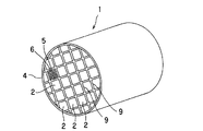
図1、2に示すように、本発明の実施の形態におけるハニカム構造体1は、多孔質の隔壁6によって区画、形成された流体の流路となる複数のセル5がハニカム構造体1の中心軸方向に互いに並行するように配設された構造を有し、それぞれが全体構造の一部を構成する形状を有するとともに、ハニカム構造体1の中心軸に対して垂直な方向に組み付けられることによって全体構造を構成することになる形状を有する複数のハニカムセグメント2が、主成分としてセラミックスを含有するとともに粒状のフィラーを含有する接合材9によって一体的に接合されて構成されてなるものである。接合材9によるハニカムセグメント2の接合の後、ハニカム構造体1の中心軸に対して垂直な平面で切断した全体の断面形状が円形、楕円形、三角形、正方形、その他の形状となるように研削加工され、外周面がコーティング材4によって被覆される。このハニカム構造体1をDPFとして用いる場合、ディーゼルエンジンの排気系等に配置することにより、ディーゼルエンジンから排出されるスートを含む粒子状物質(パティキュレート)を捕捉することができる。なお、図1においては、一つのハニカムセグメント2においてのみ、セル5及び隔壁6を示している。
As shown in FIGS. 1 and 2, the
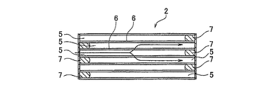
それぞれのハニカムセグメント2は、図3、4に示すように、ハニカム構造体1(図1参照)の全体構造の一部を構成する形状を有するとともに、ハニカム構造体1(図1参照)の中心軸に対して垂直な方向に組み付けられることによって全体構造を構成することになる形状を有している。セル5はハニカム構造体1の中心軸方向に互いに並行するように配設されており、隣接しているセル5におけるそれぞれの端部が交互に充填材7によって目封じされている。
As shown in FIGS. 3 and 4, each
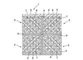
所定のセル5(流入セル)においては、図3、4における左端部側が開口している一方、右端部側が充填材7によって目封じされており、これと隣接する他のセル5(流出セル)においては、左端部側が充填材7によって目封じされるが、右端部側が開口している。このような目封じにより、図2に示すように、ハニカムセグメント2の端面が市松模様状を呈するようになる。
In the predetermined cell 5 (inflow cell), the left end side in FIGS. 3 and 4 is open, while the right end side is sealed with the
このような複数のハニカムセグメント2が接合されたハニカム構造体1を排ガスの排気系内に配置した場合、排ガスは図4における左側から各ハニカムセグメント2のセル5内に流入して右側に移動する。
When the
図4においては、ハニカムセグメント2の左側が排ガスの入口となる場合を示し、排ガスは、目封じされることなく開口しているセル5(流入セル)からハニカムセグメント2内に流入する。セル5(流入セル)に流入した排ガスは、多孔質の隔壁6を通過して他のセル5(流出セル)から流出する。そして、隔壁6を通過する際に排ガス中のスートを含む粒子状物質(パティキュレート)が隔壁6に捕捉される。
FIG. 4 shows a case where the left side of the
このようにして、排ガスの浄化を行うことができる。このような捕捉によって、ハニカムセグメント2の内部にはスートを含む粒子状物質(パティキュレート)が経時的に堆積して圧力損失が大きくなるため、スート等を燃焼させる再生が行われる。
In this way, exhaust gas can be purified. By such trapping, particulate matter containing particulates (particulates) containing soot accumulates with time in the
なお、図2〜4には、全体の断面形状が正方形のハニカムセグメント2を示すが、三角形、六角形等の形状であってもよい。また、セル5の断面形状も、三角形、六角形、円形、楕円形、その他の形状であってもよい。
2 to 4 show the
図2に示すように、接合材9は、ハニカムセグメント2の外周面に塗布されて、ハニカムセグメント2を接合するように機能する。接合材9の塗布は、隣接しているそれぞれのハニカムセグメント2の外周面に行ってもよいが、隣接したハニカムセグメント2の相互間においては、対応した外周面の一方に対してだけ行ってもよい。
As shown in FIG. 2, the
このような対応面の片側だけへの塗布は、接合材9の使用量を節約できる点で好ましい。接合材9の厚さは、ハニカムセグメント2の相互間の接合力を勘案して決定され、例えば、0.2〜4.0mmの範囲で適宜選択される。
Such application to only one side of the corresponding surface is preferable in that the amount of the
コーティング材4は、ハニカムセグメント2の接合体の外周面に塗布されて、ハニカムセグメント2の接合体の外周面を保護するように機能する。コーティング材4の厚さは、例えば、0.1〜1.5mmの範囲で適宜選択される。
The
ハニカムセグメント2の材料としては強度、耐熱性の観点から、炭化珪素、珪素−炭化珪素系複合材料、窒化珪素、コージェライト、ムライト、アルミナ、スピネル、炭化珪素−コージェライト系複合材、珪素−炭化珪素複合材、リチウムアルミニウムシリケート、チタン酸アルミニウム、Fe−Cr−Al系金属からなる群から選択される少なくとも一種を用いることが好ましい。中でも、炭化珪素又は珪素−炭化珪素系複合材料が好ましい。
As the material of the
ハニカムセグメント2の作製は、例えば、上述の材料から適宜選択したものに、メチルセルロース、ヒドロキシプロポキシルセルロース、ヒドロキシエチルセルロース、カルボキシメチルセルロース、ポリビニルアルコール等のバインダー、界面活性剤、溶媒としての水等を添加して、可塑性の坏土とし、この坏土を上述の形状となるように押出成形し、次いで、マイクロ波、熱風等によって乾燥した後、焼結することにより行うことができる。
For example, the
セル5の目封じに用いる充填材7としては、ハニカムセグメント2と同様な材料を用いることができる。充填材7による目封じは、目封じをしないセル5をマスキングした状態で、ハニカムセグメント2の端面をスラリー状の充填材7に浸漬することにより開口しているセル5に充填することにより行うことができる。充填材7の充填は、ハニカムセグメント2の成形後における焼成前に行っても、焼成後に行ってもよいが、焼成前に行うことの方が、焼成工程が1回で終了するため好ましい。
As the
以上のようなハニカムセグメント2の作製の後、ハニカムセグメント2の外周面にスラリー状の接合材9を塗布し、所定の立体形状(ハニカム構造体1の全体構造)となるように複数のハニカムセグメント2を組み付け、この組み付けた状態で圧着した後、加熱乾燥する。このようにして、複数のハニカムセグメント2が一体的に接合された接合体が作製される。その後、この接合体を上述の形状に研削加工し、外周面をコーティング材4によって被覆し、加熱乾燥する。このようにして、図1に示すハニカム構造体1が作製される。
After manufacturing the
接合材9は、主成分としてセラミックスを含有するとともに粒状のフィラーを含有する。接合材9及びコーティング材4としては、同じ材料を用いることができる。本実施の形態において、接合材9及びコーティング材4に主成分として含有されるセラミックスとしては、例えば、炭化珪素、窒化珪素、コージェライト、アルミナ、ムライト等のセラミックスを挙げることができる。これに、コロイダルシリカ、コロイダルアルミナ等のコロイダルゾル、必要に応じて金属繊維や造孔材を配合したものであってもよい。
The
接合材9及びコーティング材4に含有される粒状のフィラーとしては、例えば、無機材料又は有機材料からなるものを挙げることができる。無機材料の具体例としては、ガラスビーズ、フライアッシュバルーン等を挙げることができ、有機材料の具体例としては、澱粉、発泡樹脂等を挙げることができる。
Examples of the particulate filler contained in the
粒状のフィラーは、平均10〜300μmの直径を有することが好ましく、平均15〜250μmがさらに好ましく、平均20〜200μmが特に好ましい。粒状のフィラーの平均直径が10μm未満であると、転がり性を付与するフィラーとしての効果が発揮されず、接合材9及びコーティング材4の良好な塗布性、延び性が得られず欠陥が十分に抑制されないことがある。一方、平均径が300μmを超えると、粒子間隙が大きくなるため、塗布後の脱水速度が大きくなり、接合材9及びコーティング材4の表面が速く乾き、接合材9の場合、接合しようとするハニカムセグメント2を押し付けても十分な接合強度が得られず、コーティング材4の場合、小孔やクラック、擦れ等の欠陥が生じ易い。
The granular filler preferably has an average diameter of 10 to 300 μm, more preferably an average of 15 to 250 μm, and particularly preferably an average of 20 to 200 μm. When the average diameter of the granular filler is less than 10 μm, the effect as a filler imparting rolling properties is not exhibited, and the
粒状のフィラーは、長中心軸/短中心軸比が1.0〜4.0の範囲にあることが好ましく、真球であることがさらに好ましい。 The granular filler preferably has a major axis / minor axis ratio in the range of 1.0 to 4.0, and more preferably a true sphere.
粒状のフィラーは、接合材9及びコーティング材4に、20〜70体積%の割合で含有されることが好ましい。25〜65体積%であることがさらに好ましく、30〜60体積%であることが特に好ましい。含有割合が20体積%未満であると、フィラーとしての効果が発揮されないことがあり、70体積%を超えると、必要な強度が得られないことがある。
The particulate filler is preferably contained in the
粒状のフィラーは、中空構造を有することが好ましい。中空構造を有する粒子(中空粒子)を用いることにより、接合材9及びコーティング材4が硬化して形成される接合部及び外周面の密度が低下し、ヤング率を低減することが可能となる。これにより、接合部及び外周面の耐熱衝撃性が向上し、使用時のクラック発生を抑制することができる。
The granular filler preferably has a hollow structure. By using particles having a hollow structure (hollow particles), the density of the bonded portion and the outer peripheral surface formed by curing the
本実施の形態において、接合材9及びコーティング材4は、上述のセラミックス及び粒状のフィラーに加えて、無機粒子、酸化物繊維及びコロイド状酸化物からなる群から選ばれる少なくとも一種を5〜60質量%の割合でさらに含有してもよい。これらを含有させることにより、接合材9及びコーティング材4としての特性を向上させることができる。
In the present embodiment, the
無機粒子としては、例えば、炭化珪素、窒化珪素、コージェライト、アルミナ、ムライト、ジルコニア、燐酸ジルコニウム、アルミニウムチタネート及びチタニアからなる群から選ばれる少なくとも一種のセラミックス;Fe−Cr−Al系金属;ニッケル系金属;金属Si;SiC等を挙げることができる。 Examples of the inorganic particles include at least one ceramic selected from the group consisting of silicon carbide, silicon nitride, cordierite, alumina, mullite, zirconia, zirconium phosphate, aluminum titanate, and titania; Fe—Cr—Al-based metal; nickel-based Metal; metal Si; SiC and the like can be mentioned.
酸化物繊維としては、例えば、アルミノシリケート質繊維、その他の繊維を挙げることができる。 Examples of oxide fibers include aluminosilicate fibers and other fibers.
コロイド状酸化物としては、例えば、シリカゾル、アルミナゾル等を挙げることができる。 Examples of the colloidal oxide include silica sol and alumina sol.
接合材9及びコーティング材4の熱伝導率は、0.1〜5.0W/m・kであることが好ましく、0.2〜3.0W/m・kであることがさらに好ましい。熱伝導率が0.1W/m・k未満であると、ハニカムセグメント2間の熱伝達を阻害してハニカム構造体1内の温度を不均一にすることがある。熱伝導率が5.0W/m・kを超えると、接合強度が低下することがあるとともに、ハニカム構造体1の製造が困難となることがある。
The thermal conductivity of the
接合材9及びコーティング材4の熱膨張率は、熱衝撃等によってクラックが発生するを防止するため、比較的低いことが好ましく、1×10⁻⁶〜8×10⁻⁶/℃の範囲であることが好ましい。1.5×10−6〜7×10−6/℃の範囲であることがさらに好ましく、2×10−6〜6×10−6/℃の範囲であることが特に好ましい。
The thermal expansion coefficients of the
以下、本発明を実施例によってさらに具体的に説明するが、本発明は、これらの実施例によっていかなる制限を受けるものではない。 Hereinafter, the present invention will be described more specifically with reference to examples. However, the present invention is not limited to these examples.
本実施例では、原料としてSiC粉末及びSi粉末を80:20の重量割合で混合し、これに造孔材として澱粉、発泡樹脂を加え、さらにメチルセルロース及びヒドロキシプロポキシルメチルセルロース、界面活性剤及び水を添加して、可塑性の坏土を作製した。この坏土を押出成形し、マイクロ波及び熱風で乾燥して隔壁の厚さが310μm、セル密度が約46.5セル/cm2(300セル/平方インチ)、断面形状が一辺35mmの正方形、長さが152mmのハニカムセグメントを得た。 In this example, SiC powder and Si powder as raw materials were mixed at a weight ratio of 80:20, starch and foamed resin were added as pore formers, and methylcellulose and hydroxypropoxylmethylcellulose, surfactant and water were added. Addition to make a plastic clay. This clay is extruded and dried with microwaves and hot air to form a partition wall having a thickness of 310 μm, a cell density of about 46.5 cells / cm 2 (300 cells / square inch), a cross-sectional shape of a square having a side of 35 mm, A honeycomb segment having a length of 152 mm was obtained.
このハニカムセグメントに対し、端面が市松模様状を呈するように、隣接するセルが互いに反対側となる一方の端部でハニカムセグメントの製造に用いた材料と同様の材料と用いて目封じし、乾燥させた後、大気雰囲気中約400℃で脱脂し、その後、Ar不活性雰囲気中で約1450℃で焼成して、Si結合SiCの焼成ハニカムセグメントを得た。 The honeycomb segment is sealed with a material similar to the material used for manufacturing the honeycomb segment at one end where adjacent cells are opposite to each other so that the end face has a checkered pattern, and is dried. After degreasing, degreasing was performed at about 400 ° C. in an air atmosphere, followed by firing at about 1450 ° C. in an Ar inert atmosphere to obtain a fired honeycomb segment of Si-bonded SiC.
一方、フィラーとして発泡樹脂(アクリルニトリル樹脂)、有機バインダーとしてメチルセルロース、無機粒子としてSiC粉末、酸化物繊維としてアルミノシリケート質繊維、無機バインダーとしてシリカゲル40質量%水溶液及び粘土を混合し、水を加えて、ミキサーを用いて30分間混練し、表1に示す組成の接合材A〜Kを得た。表1における接合材A〜Kの内、接合材A〜Iは後述するように、本発明の参考例に用いられ、接合材J、Kは比較例に用いられる。 On the other hand, foam resin (acrylonitrile resin) as filler, methyl cellulose as organic binder, SiC powder as inorganic particles, aluminosilicate fiber as oxide fiber, silica gel 40% by weight aqueous solution and clay are mixed, and water is added. Then, the mixture was kneaded for 30 minutes using a mixer to obtain bonding materials A to K having the compositions shown in Table 1. Among the bonding materials A to K in Table 1, the bonding materials A to I are used in a reference example of the present invention as described later, and the bonding materials J and K are used in a comparative example.
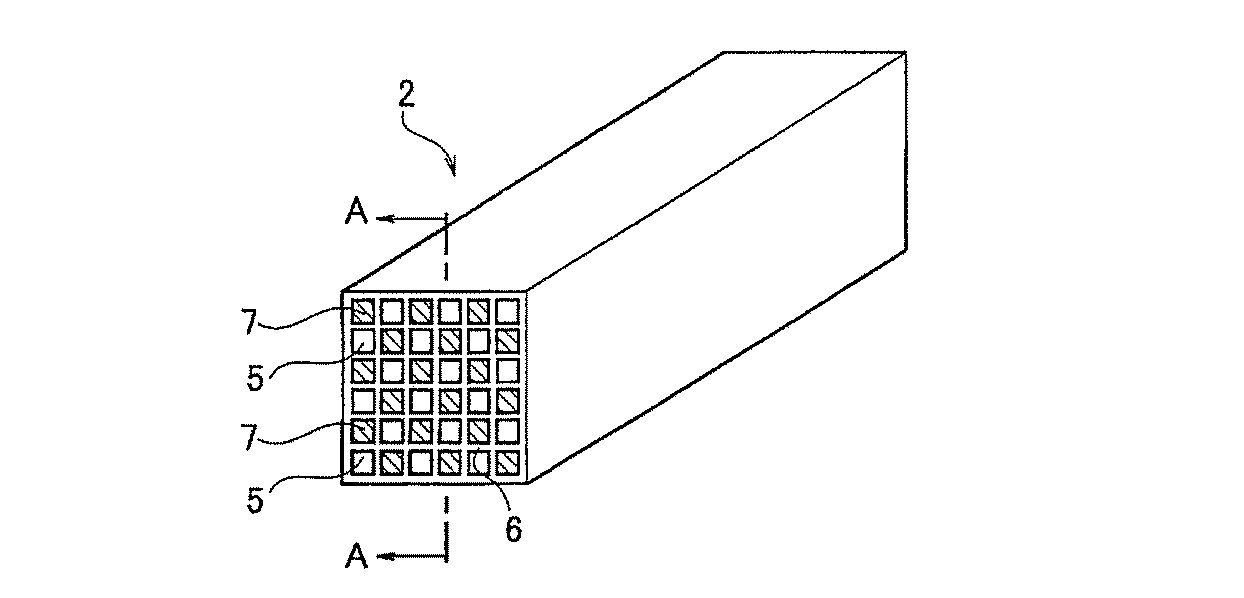
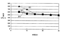
表2は、表1に示す接合材B、H、Kについてミキサーによって混練中に、一定時間毎に粘度を測定した結果を示す。図5は、接合材B、H、Kへの混練による粘度の時間的変化を示す。図5において、特性曲線B1は接合材B、特性曲線H1は接合材H、特性曲線K1は接合材Kをそれぞれ用いた場合を示す。 Table 2 shows the results of measuring the viscosity of the bonding materials B, H, and K shown in Table 1 at regular intervals during kneading with a mixer. FIG. 5 shows changes in viscosity with time due to kneading into the bonding materials B, H, and K. In FIG. 5, the characteristic curve B1 shows the case where the bonding material B, the characteristic curve H1 uses the bonding material H, and the characteristic curve K1 shows the case where the bonding material K is used.
これらの結果からわかるように、有機バインダーを添加した接合材K(特性曲線K1)では混練初期に粘度が増大した後、15分を過ぎた時点付近から粘度変化がほぼ見られなくなる。これに対し、発泡樹脂を添加した接合材B(特性曲線B1)及び接合材H(特性曲線H1)では、混練を通じて粘度変化がほとんど見られない。 As can be seen from these results, in the bonding material K (characteristic curve K1) to which the organic binder is added, after the viscosity increases in the initial stage of kneading, the viscosity change is hardly seen from around 15 minutes. On the other hand, in the bonding material B (characteristic curve B1) and the bonding material H (characteristic curve H1) to which the foamed resin is added, there is almost no change in viscosity through kneading.
次に、表1に示す接合材を用いて焼成ハニカムセグメントを接合した。この接合では、接合材の厚みが1mmとなるように、各々複数個ずつ接合した後、200℃、5時間乾燥
して、参考例1〜9及び比較例1のハニカム構造体を得た。それぞれのハニカム構造体か
ら、所定の強度試験用サンプルを10個ずつ切り出し、JIS R1601に従って3点
曲げ接合強度の測定を行なった。結果を表3に示す。
Next, the fired honeycomb segments were joined using the joining materials shown in Table 1. In this joining, a plurality of joining materials were joined so that the thickness of the joining material was 1 mm, and then dried at 200 ° C. for 5 hours to obtain honeycomb structures of Reference Examples 1 to 9 and Comparative Example 1. Ten predetermined strength test samples were cut out from each honeycomb structure, and three-point bending joint strength was measured according to JIS R1601. The results are shown in Table 3.
表3に示すように、フィラーを添加しない接合材(接合材J)を用いた比較例1の場合、接合部に大きな剥れが見られた。また、同様に平均径が10〜300μmの範囲を外れる発泡樹脂を添加した接合材(接合材F、G)を用いた参考例6、7の場合、及び発泡樹脂の添加量が20〜70体積%の範囲を外れる接合材(接合材H、I)を用いた参考例8、9の場合、延び性不良のために、接合部にごく一部の剥れが見られたり、接合強度がやや低い値となった。 As shown in Table 3, in the case of the comparative example 1 using the joining material (joining material J) which does not add a filler, big peeling was seen by the junction part. Similarly, in the case of Reference Examples 6 and 7 using a bonding material (bonding materials F and G) to which a foamed resin with an average diameter outside the range of 10 to 300 μm is added, and the amount of the foamed resin added is 20 to 70 volumes. In the case of Reference Examples 8 and 9 using bonding materials (bonding materials H and I) outside the range of%, due to poor ductility, only a part of the bonding portion was peeled off or the bonding strength was slightly The value was low.
さらに、接合材B、Jを用いた参考例10、比較例1の場合に対して密度と強度/ヤング率比を比較した。結果を表4に示す。 Furthermore, the density and the strength / Young's modulus ratio were compared with those of Reference Example 10 and Comparative Example 1 using the bonding materials B and J. The results are shown in Table 4.
表4に示すように、中空の発泡樹脂を添加した接合材Bを用いた参考例10の場合の方が、中空の発泡樹脂を添加しない接合材Jを用いた比較例1の場合よりも、強度/ヤング率比が向上することが確認された。これにより使用時の耐熱衝撃性の向上が期待できる。 As shown in Table 4, the case of Reference Example 10 using the bonding material B to which the hollow foamed resin was added was more than the case of Comparative Example 1 using the bonding material J to which the hollow foamed resin was not added. It was confirmed that the strength / Young's modulus ratio was improved. This can be expected to improve the thermal shock resistance during use.
さらに、表1に示す接合材A〜Jのそれぞれに、水を添加してコーティング可能な粘度に調整することにより、コーティング材L〜Uを作製した。そして、焼成ハニカムセグメントを16本接合して得られた接合体の外周を研削した後、その外周部に対してコーティング材L〜Uをそれぞれ個別に塗布し、200℃で2時間乾燥して、実施例1〜5、参考例11〜14及び比較例2のハニカム構造体を得た。表5に、添加水分量(質量%)及びこのハニカム構造体のコーティング層の外観(小孔、クラック、擦れの有無)を、目視によって検査した結果を示す。 Furthermore, coating materials L to U were prepared by adding water to each of the bonding materials A to J shown in Table 1 to adjust the viscosity so that coating was possible. And after grinding the outer periphery of the joined body obtained by joining 16 fired honeycomb segments, the coating materials L to U were individually applied to the outer periphery, and dried at 200 ° C. for 2 hours, The honeycomb structures of Examples 1 to 5, Reference Examples 11 to 14, and Comparative Example 2 were obtained. Table 5 shows the result of visual inspection of the amount of added water (% by mass) and the appearance of the coating layer of the honeycomb structure (presence / absence of small holes, cracks, and rubbing).
表5に示すように、フィラーを添加しないコーティング材(コーティング材U)を用いた比較例2の場合、小孔、クラック、擦れからなる欠陥が生じた。また、平均直径が10〜300μmの範囲を外れるフィラーを添加したコーティング材Q、R及びフィラーの含有量が20〜70体積%の範囲を外れるコーティング材S、Tを用いた参考例11〜14の場合、小孔、クラック、擦れの一部からなる欠陥が若干生じた。 As shown in Table 5, in Comparative Example 2 using a coating material (coating material U) to which no filler was added, defects consisting of small holes, cracks, and rubbing occurred. Further, Reference Examples 1 to 1 using coating materials Q and R to which a filler whose average diameter is outside the range of 10 to 300 μm and coating materials S and T whose filler content is outside the range of 20 to 70% by volume are added. In the case of No. 4, some defects consisting of small holes, cracks, and part of rubbing occurred.
本発明のハニカム構造体は、排ガス用の捕集フィルタとして、例えば、ディーゼルエンジン等からの排ガスに含まれている粒子状物質(パティキュレート)を捕捉して除去するためのディーゼルパティキュレートフィルタ(DPF)として有用である。 The honeycomb structure of the present invention is a diesel particulate filter (DPF) for capturing and removing particulate matter (particulates) contained in exhaust gas from a diesel engine or the like, for example, as a collection filter for exhaust gas. ) Is useful.
1…ハニカム構造体、2…ハニカムセグメント、4…コーティング材、5…セル、6…隔壁、7…充填材、9…接合材。
DESCRIPTION OF
Claims (3)
前記粒状のフィラーが塗布性および延び性を前記コーティング材に付与するものであることを特徴とするハニカム構造体。 A honeycomb structure having a structure in which a plurality of cells, which are partitioned and formed by porous partition walls, are arranged in parallel to each other in the central axis direction, each of which is a part of the entire structure And a plurality of honeycomb segments having a shape that constitutes the overall structure by being assembled in a direction perpendicular to the central axis are integrally joined by a joining material. And the outer peripheral surface of the joined body is coated with a coating material containing 20 to 70% by volume of a granular filler having an average diameter of 10 to 300 μm and 9 to 13% by mass of water while containing ceramics as a main component. Being
The honeycomb structure according to claim 1, wherein the granular filler imparts coating properties and stretchability to the coating material.
Priority Applications (1)
| Application Number | Priority Date | Filing Date | Title |
|---|---|---|---|
| JP2011209119A JP5524924B2 (en) | 2003-11-12 | 2011-09-26 | Honeycomb structure |
Applications Claiming Priority (3)
| Application Number | Priority Date | Filing Date | Title |
|---|---|---|---|
| JP2003382536 | 2003-11-12 | ||
| JP2003382536 | 2003-11-12 | ||
| JP2011209119A JP5524924B2 (en) | 2003-11-12 | 2011-09-26 | Honeycomb structure |
Related Parent Applications (1)
| Application Number | Title | Priority Date | Filing Date |
|---|---|---|---|
| JP2005515446A Division JP5281733B2 (en) | 2003-11-12 | 2004-11-11 | Honeycomb structure |
Publications (2)
| Publication Number | Publication Date |
|---|---|
| JP2012046417A JP2012046417A (en) | 2012-03-08 |
| JP5524924B2 true JP5524924B2 (en) | 2014-06-18 |
Family
ID=34587257
Family Applications (2)
| Application Number | Title | Priority Date | Filing Date |
|---|---|---|---|
| JP2005515446A Expired - Fee Related JP5281733B2 (en) | 2003-11-12 | 2004-11-11 | Honeycomb structure |
| JP2011209119A Expired - Fee Related JP5524924B2 (en) | 2003-11-12 | 2011-09-26 | Honeycomb structure |
Family Applications Before (1)
| Application Number | Title | Priority Date | Filing Date |
|---|---|---|---|
| JP2005515446A Expired - Fee Related JP5281733B2 (en) | 2003-11-12 | 2004-11-11 | Honeycomb structure |
Country Status (6)
| Country | Link |
|---|---|
| US (1) | US7435279B2 (en) |
| EP (1) | EP1686108B1 (en) |
| JP (2) | JP5281733B2 (en) |
| KR (1) | KR100608034B1 (en) |
| PL (1) | PL1686108T3 (en) |
| WO (1) | WO2005047209A1 (en) |
Families Citing this family (35)
| Publication number | Priority date | Publication date | Assignee | Title |
|---|---|---|---|---|
| FR2874964B1 (en) * | 2004-09-06 | 2009-05-29 | Saint Gobain Ct Recherches | EXHAUST GAS FILTRATION STRUCTURE OF AN INTERNAL COMBUSTION ENGINE AND EXHAUST LINE THEREFOR |
| JP4948393B2 (en) * | 2005-03-02 | 2012-06-06 | イビデン株式会社 | Inorganic fiber aggregate, method for manufacturing inorganic fiber aggregate, honeycomb structure, and method for manufacturing honeycomb structure |
| US20060272306A1 (en) * | 2005-06-01 | 2006-12-07 | Kirk Brian S | Ceramic wall flow filter manufacture |
| JP4616752B2 (en) * | 2005-10-26 | 2011-01-19 | 日本碍子株式会社 | Honeycomb structure |
| WO2007069674A1 (en) * | 2005-12-14 | 2007-06-21 | Ngk Insulators, Ltd. | Bonding material, process for producing the same, and honeycomb structure made with the same |
| JPWO2007086183A1 (en) | 2006-01-27 | 2009-06-18 | イビデン株式会社 | Honeycomb structure and manufacturing method thereof |
| EP1813339B1 (en) * | 2006-01-27 | 2013-03-06 | Ibiden Co., Ltd. | Honeycomb structure and method for manufacturing honeycomb structure |
| EP2006265B1 (en) * | 2006-03-24 | 2018-01-03 | NGK Insulators, Ltd. | Bonded body |
| JP2007260595A (en) * | 2006-03-29 | 2007-10-11 | Ngk Insulators Ltd | Honeycomb structure |
| KR101081638B1 (en) * | 2006-03-30 | 2011-11-09 | 엔지케이 인슐레이터 엘티디 | Bonded element, honeycomb segment bonded element, and honeycomb structure using the same |
| FR2902424B1 (en) * | 2006-06-19 | 2008-10-17 | Saint Gobain Ct Recherches | HOLLOW SPHERES JOINTING CEMENT FOR PARTICLE FILTER. |
| WO2008120390A1 (en) * | 2007-03-29 | 2008-10-09 | Ibiden Co., Ltd. | Process for producing honeycomb structure and honeycomb structure |
| EP1982966B1 (en) | 2007-03-29 | 2011-11-09 | Ibiden Co., Ltd. | Honeycomb structure and method of producing honeycomb structure |
| WO2008126308A1 (en) * | 2007-03-30 | 2008-10-23 | Ibiden Co., Ltd. | Catalyst carrier |
| JP4873326B2 (en) * | 2007-03-30 | 2012-02-08 | イビデン株式会社 | Honeycomb structure |
| JP5486305B2 (en) * | 2007-07-26 | 2014-05-07 | 日本碍子株式会社 | Bonding material for honeycomb structure and honeycomb structure using the bonding material |
| EP2179977B1 (en) * | 2007-07-26 | 2018-08-22 | NGK Insulators, Ltd. | Coating material for honeycomb structure |
| JP4480758B2 (en) * | 2007-12-27 | 2010-06-16 | 日本碍子株式会社 | Refractory mortar cured molding |
| DE102008004036B3 (en) * | 2008-01-11 | 2009-07-09 | Audi Ag | Producing honeycomb structure body for a catalyst of a motor vehicle, comprises forming a honeycomb structure body having fluid channels with an outer skin surrounding a honeycomb area as an external circumference wall |
| WO2009095982A1 (en) * | 2008-01-28 | 2009-08-06 | Ibiden Co., Ltd. | Honeycomb structure |
| USD647607S1 (en) | 2008-05-27 | 2011-10-25 | Ibiden Co., Ltd. | Particulate filter for diesel engine |
| USD609319S1 (en) * | 2008-06-19 | 2010-02-02 | Ibiden Co., Ltd. | Particulate filter for diesel engine |
| USD609320S1 (en) * | 2008-06-19 | 2010-02-02 | Ibiden Co., Ltd. | Particulate filter for diesel engine |
| FR2937971B1 (en) * | 2008-10-30 | 2011-08-26 | Saint Gobain Ct Recherches | BODY ASSEMBLED WITH MACROPOROUS CURED CEMENT |
| EP2358359B1 (en) | 2008-12-15 | 2019-04-17 | Unifrax I LLC | Ceramic honeycomb structure skin coating |
| JP5345501B2 (en) * | 2009-10-19 | 2013-11-20 | 東京窯業株式会社 | Outer coating |
| US8999483B2 (en) | 2010-11-29 | 2015-04-07 | Corning Incorporated | Honeycomb structure comprising an outer cement skin and a cement therefor |
| JP6077484B2 (en) * | 2014-03-26 | 2017-02-08 | 日本碍子株式会社 | Honeycomb structure |
| JP6174511B2 (en) | 2014-03-31 | 2017-08-02 | 日本碍子株式会社 | Honeycomb structure |
| US9808055B1 (en) * | 2015-01-21 | 2017-11-07 | National Chain Company | Jewelry setting |
| JP6530680B2 (en) * | 2015-09-02 | 2019-06-12 | 日本碍子株式会社 | Plugged honeycomb structure and plugged honeycomb segment |
| CN110465137A (en) * | 2019-08-05 | 2019-11-19 | 江西博鑫精陶环保科技有限公司 | A kind of high-temperature dust nitre integrally purifies the flange and its preparation process of ceramic element |
| CN114302764B (en) * | 2019-09-11 | 2023-12-26 | 日本碍子株式会社 | Honeycomb structure and exhaust gas purification device |
| JP7820203B2 (en) * | 2022-03-24 | 2026-02-25 | 日本碍子株式会社 | Honeycomb structure, electrically heated carrier and exhaust gas purification device |
| CN115628274B (en) * | 2022-09-14 | 2025-03-11 | 中国人民解放军国防科技大学 | A lightweight impact-reducing material for spacecraft pyrotechnic separation |
Family Cites Families (35)
| Publication number | Priority date | Publication date | Assignee | Title |
|---|---|---|---|---|
| JP2613729B2 (en) * | 1992-01-30 | 1997-05-28 | 日本碍子株式会社 | Ceramic honeycomb structure, method of manufacturing the same, and coating material therefor |
| JP3121497B2 (en) | 1994-07-14 | 2000-12-25 | イビデン株式会社 | Ceramic structure |
| DK0816065T3 (en) * | 1996-01-12 | 2004-03-22 | Ibiden Co Ltd | Ceramic structure |
| EP1508356B1 (en) * | 1999-09-29 | 2006-12-13 | Ibiden Co., Ltd. | Honeycomb filter and ceramic filter assembly |
| JP4394329B2 (en) * | 2001-03-01 | 2010-01-06 | 日本碍子株式会社 | Manufacturing method of ceramic structure |
| JP4408183B2 (en) * | 2001-03-16 | 2010-02-03 | 日本碍子株式会社 | Honeycomb filter for exhaust gas purification |
| JP2002273130A (en) * | 2001-03-22 | 2002-09-24 | Ngk Insulators Ltd | Honeycomb structure |
| JP4511070B2 (en) * | 2001-03-29 | 2010-07-28 | 日本碍子株式会社 | Honeycomb structure and assembly thereof |
| JP4511071B2 (en) * | 2001-03-29 | 2010-07-28 | 日本碍子株式会社 | Honeycomb structure and assembly thereof |
| JP2002292225A (en) * | 2001-03-30 | 2002-10-08 | Ngk Insulators Ltd | Honeycomb structure and its assembly |
| JP4094823B2 (en) * | 2001-04-03 | 2008-06-04 | 日本碍子株式会社 | Honeycomb structure and assembly thereof |
| JP2003010616A (en) * | 2001-06-29 | 2003-01-14 | Ngk Insulators Ltd | Honeycomb structure |
| JP3983117B2 (en) * | 2001-07-31 | 2007-09-26 | 日本碍子株式会社 | Honeycomb structure and manufacturing method thereof |
| JP4367683B2 (en) * | 2001-10-09 | 2009-11-18 | 日本碍子株式会社 | Honeycomb filter |
| JP4246425B2 (en) * | 2001-10-15 | 2009-04-02 | 日本碍子株式会社 | Honeycomb filter |
| JP3893049B2 (en) * | 2001-11-20 | 2007-03-14 | 日本碍子株式会社 | Honeycomb structure and manufacturing method thereof |
| JP4266103B2 (en) * | 2001-12-07 | 2009-05-20 | 日本碍子株式会社 | Method for producing porous ceramic body |
| ATE407285T1 (en) * | 2002-02-05 | 2008-09-15 | Ibiden Co Ltd | HONEYCOMB FILTER FOR EXHAUST GAS DETOXIFICATION |
| EP1719881B1 (en) * | 2002-02-05 | 2016-12-07 | Ibiden Co., Ltd. | Honeycomb filter for exhaust gas decontamination, adhesive, coating material and process for producing honeycomb filter for exhaust gas decontamination |
| JP4157304B2 (en) * | 2002-02-05 | 2008-10-01 | 日本碍子株式会社 | Honeycomb structure |
| EP1489274B2 (en) * | 2002-03-04 | 2013-06-05 | Ibiden Co., Ltd. | Use of a honeycomb filter for exhaust gas purification |
| JP4293753B2 (en) * | 2002-03-19 | 2009-07-08 | 日本碍子株式会社 | Honeycomb filter |
| JP4229843B2 (en) * | 2002-03-22 | 2009-02-25 | イビデン株式会社 | Honeycomb filter for exhaust gas purification |
| DE60324121D1 (en) * | 2002-03-29 | 2008-11-27 | Ibiden Co Ltd | CERAMIC FILTER AND EXHAUST CONTAMINATION UNIT |
| JP2003291054A (en) * | 2002-03-29 | 2003-10-14 | Ngk Insulators Ltd | Method for manufacturing honeycomb structure |
| EP2020486A3 (en) * | 2002-04-10 | 2009-04-15 | Ibiden Co., Ltd. | Honeycomb filter for clarifying exhaust gas |
| CN1322909C (en) * | 2002-09-13 | 2007-06-27 | 揖斐电株式会社 | honeycomb structure |
| EP1550646A4 (en) * | 2002-10-07 | 2006-04-26 | Ibiden Co Ltd | STRUCTURAL BODY IN HONEYCOMB |
| WO2004031100A1 (en) * | 2002-10-07 | 2004-04-15 | Ibiden Co., Ltd. | Honeycomb structural body |
| JP2004261623A (en) * | 2003-01-08 | 2004-09-24 | Ngk Insulators Ltd | Honeycomb structure |
| JP4382367B2 (en) * | 2003-01-14 | 2009-12-09 | 日本碍子株式会社 | Method for joining ceramic honeycomb structures |
| JP4267947B2 (en) * | 2003-03-19 | 2009-05-27 | 日本碍子株式会社 | Honeycomb structure |
| WO2004096414A1 (en) * | 2003-03-19 | 2004-11-11 | Ngk Insulators Ltd. | Honeycomb structure body |
| KR101014399B1 (en) * | 2003-08-12 | 2011-02-15 | 엔지케이 인슐레이터 엘티디 | Ceramic filter |
| CN100526615C (en) * | 2003-12-25 | 2009-08-12 | 揖斐电株式会社 | Exhaust gas purifying device and method for recovering exhaust gas purifying device |
-
2004
- 2004-11-11 US US10/532,310 patent/US7435279B2/en not_active Expired - Lifetime
- 2004-11-11 KR KR1020057007572A patent/KR100608034B1/en not_active Expired - Fee Related
- 2004-11-11 WO PCT/JP2004/016760 patent/WO2005047209A1/en not_active Ceased
- 2004-11-11 EP EP04799621A patent/EP1686108B1/en not_active Expired - Lifetime
- 2004-11-11 PL PL04799621T patent/PL1686108T3/en unknown
- 2004-11-11 JP JP2005515446A patent/JP5281733B2/en not_active Expired - Fee Related
-
2011
- 2011-09-26 JP JP2011209119A patent/JP5524924B2/en not_active Expired - Fee Related
Also Published As
| Publication number | Publication date |
|---|---|
| EP1686108A4 (en) | 2010-02-24 |
| JP2012046417A (en) | 2012-03-08 |
| KR20060055432A (en) | 2006-05-23 |
| US20060101747A1 (en) | 2006-05-18 |
| KR100608034B1 (en) | 2006-08-08 |
| EP1686108A1 (en) | 2006-08-02 |
| PL1686108T3 (en) | 2012-02-29 |
| US7435279B2 (en) | 2008-10-14 |
| EP1686108B1 (en) | 2011-09-14 |
| JP5281733B2 (en) | 2013-09-04 |
| WO2005047209A1 (en) | 2005-05-26 |
| JPWO2005047209A1 (en) | 2007-05-31 |
Similar Documents
| Publication | Publication Date | Title |
|---|---|---|
| JP5524924B2 (en) | Honeycomb structure | |
| KR101081638B1 (en) | Bonded element, honeycomb segment bonded element, and honeycomb structure using the same | |
| JP5367363B2 (en) | Bonded body, bonded material composition, honeycomb segment bonded body, and honeycomb structure using the same | |
| KR100845205B1 (en) | Honeycomb structure | |
| JP4267947B2 (en) | Honeycomb structure | |
| JP5103378B2 (en) | Honeycomb structure | |
| JP6043286B2 (en) | Honeycomb structure | |
| JP4890857B2 (en) | Honeycomb structure | |
| KR100893514B1 (en) | Honeycomb structure | |
| KR100833140B1 (en) | Honeycomb Structure | |
| JP2006281134A (en) | Honeycomb structure | |
| JP4434076B2 (en) | Honeycomb structure | |
| JP4607689B2 (en) | Honeycomb structure | |
| JP5313878B2 (en) | Honeycomb structure using honeycomb segment | |
| JP4616752B2 (en) | Honeycomb structure | |
| JPWO2008096569A1 (en) | DPF honeycomb segment bonded body and bonded material composition for bonded body | |
| JP2007075733A (en) | Honeycomb segment and honeycomb structure using the same |
Legal Events
| Date | Code | Title | Description |
|---|---|---|---|
| A131 | Notification of reasons for refusal |
Free format text: JAPANESE INTERMEDIATE CODE: A131 Effective date: 20130528 |
|
| A521 | Request for written amendment filed |
Free format text: JAPANESE INTERMEDIATE CODE: A523 Effective date: 20130704 |
|
| A131 | Notification of reasons for refusal |
Free format text: JAPANESE INTERMEDIATE CODE: A131 Effective date: 20140121 |
|
| TRDD | Decision of grant or rejection written | ||
| A01 | Written decision to grant a patent or to grant a registration (utility model) |
Free format text: JAPANESE INTERMEDIATE CODE: A01 Effective date: 20140408 |
|
| A61 | First payment of annual fees (during grant procedure) |
Free format text: JAPANESE INTERMEDIATE CODE: A61 Effective date: 20140410 |
|
| R150 | Certificate of patent or registration of utility model |
Ref document number: 5524924 Country of ref document: JP Free format text: JAPANESE INTERMEDIATE CODE: R150 |
|
| LAPS | Cancellation because of no payment of annual fees |