JP5518159B2 - Rechargeable power tool - Google Patents

Rechargeable power tool Download PDF

Info

Publication number
JP5518159B2
JP5518159B2 JP2012222346A JP2012222346A JP5518159B2 JP 5518159 B2 JP5518159 B2 JP 5518159B2 JP 2012222346 A JP2012222346 A JP 2012222346A JP 2012222346 A JP2012222346 A JP 2012222346A JP 5518159 B2 JP5518159 B2 JP 5518159B2
Authority
JP
Japan
Prior art keywords
handle portion
opening
battery pack
seal member
switch
Prior art date
Legal status (The legal status is an assumption and is not a legal conclusion. Google has not performed a legal analysis and makes no representation as to the accuracy of the status listed.)
Active
Application number
JP2012222346A
Other languages
Japanese (ja)
Other versions
JP2012254526A (en
JP2012254526A5 (en
Inventor
英紀 長坂
竜之助 熊谷
Current Assignee (The listed assignees may be inaccurate. Google has not performed a legal analysis and makes no representation or warranty as to the accuracy of the list.)
Makita Corp
Original Assignee
Makita Corp
Priority date (The priority date is an assumption and is not a legal conclusion. Google has not performed a legal analysis and makes no representation as to the accuracy of the date listed.)
Filing date
Publication date
Application filed by Makita Corp filed Critical Makita Corp
Priority to JP2012222346A priority Critical patent/JP5518159B2/en
Publication of JP2012254526A publication Critical patent/JP2012254526A/en
Publication of JP2012254526A5 publication Critical patent/JP2012254526A5/ja
Application granted granted Critical
Publication of JP5518159B2 publication Critical patent/JP5518159B2/en
Active legal-status Critical Current
Anticipated expiration legal-status Critical

Links

Images

Description

この発明は、開口部を備えたハウジングの前記開口部よりも下方に形成した装着部に、電源となるバッテリーパックを着脱自在に装着する充電式電動工具に関する。   The present invention relates to a rechargeable electric tool in which a battery pack serving as a power source is detachably attached to a mounting portion formed below the opening of a housing having an opening.

例えば特許文献1には、モータや駆動機構等を収容したハウジングに連設されたグリップ部を備えて、グリップ部の底部に開口形成したバッテリー装着部に、バッテリーパックを着脱可能な充電式電動工具が開示されている。   For example, Patent Document 1 discloses a rechargeable electric tool that includes a grip portion that is connected to a housing that houses a motor, a drive mechanism, and the like, and that can be attached to and detached from a battery mounting portion that is open at the bottom of the grip portion. Is disclosed.

一般に、特許文献1の充電式電動工具等では、ハウジングに開口を設けて、電気的な操作を行うために必要なスイッチのトリガを露出させたり、ハウジングに通気口を設けてモータの冷却を行っている。   In general, in the rechargeable electric power tool disclosed in Patent Document 1, an opening is provided in the housing to expose a switch trigger necessary for electrical operation, or a vent is provided in the housing to cool the motor. ing.

特開2009−78322号公報JP 2009-78322 A

しかしながら、例えば上記の充電式電動工具を屋外に放置した状態で雨が降り出した場合等には、上記の開口や通気口等の開口部から、雨水等がハウジング内に浸入することがあった。このような場合には、ハウジング内に浸入した雨水等が、グリップ部やバッテリー装着部を通過した後に、バッテリー装着部とバッテリーパックとの隙間やバッテリーパックに浸入することになり、前記隙間やバッテリーパックに対する防水性が十分であるとは言い難かった。   However, for example, when rain starts when the rechargeable power tool is left outdoors, rainwater or the like may enter the housing from the openings such as the openings or vents. In such a case, rainwater or the like that has entered the housing passes through the grip portion or the battery mounting portion, and then enters the gap between the battery mounting portion and the battery pack or into the battery pack. It was difficult to say that the waterproofness of the pack was sufficient.

この発明は、このような状況に鑑み提案されたものであって、バッテリーパックの装着部とバッテリーパックとの隙間やバッテリーパックに対する防水性を向上させた充電式電動工具を提供することを目的とする。   The present invention has been proposed in view of such a situation, and an object of the present invention is to provide a rechargeable electric tool with improved waterproofness against a gap between the battery pack mounting portion and the battery pack and the battery pack. To do.

請求項1の発明に係る充電式電動工具は、前後方向に延設された胴体部と、前記胴体部から該胴体部の下方に延びるハンドル部と、前記ハンドル部の下端に形成されて電源となるバッテリーパックを着脱自在に装着するバッテリー装着部と、を有する本体ハウジングと、前記胴体部の内部に収容されたモータと、前記胴体部に設けられて、前記モータの冷却風を吸気する吸気口と、前記胴体部に設けられて、前記冷却風を前記胴体部の外部へ排出する排気口と、前記胴体部に、前記モータの前方で組み付けられて、先端工具を装着可能で前記モータの回転が伝達されるチャックと、前記ハンドル部の内部に収容されて、該ハンドル部から露出して前記ハンドル部の内部に押し込み可能なトリガを有して、前記バッテリーパックから前記モータへの電力供給を制御するスイッチと、を備えた充電式電動工具であって、前記ハンドル部に、前記トリガを該ハンドル部から露出させる開口を設け、前記スイッチの外面に対して前記ハンドル部の内部の前記胴体部側と該ハンドル部の内部の前記バッテリー装着部側との間をシールするように配置した弾性体を、前記開口に向かうように下り傾斜させて、前記吸気口と前記排気口との少なくとも一方から前記胴体部の内部に浸入した水を、前記ハンドル部の内部を通過させて前記弾性体によって前記開口に導いて、前記開口から前記ハンドル部の外部へ排出可能としたことを特徴とする。 A rechargeable electric tool according to the invention of claim 1 is provided with a body portion extending in the front-rear direction, a handle portion extending from the body portion to the lower portion of the body portion, and a power source formed at a lower end of the handle portion. A battery housing for detachably mounting the battery pack, a motor housed in the body, and an air inlet provided in the body for sucking cooling air from the motor And an exhaust port provided in the body part for discharging the cooling air to the outside of the body part, and the body part is assembled in front of the motor, and a tip tool can be attached to rotate the motor. And a trigger that is housed inside the handle portion and that is exposed from the handle portion and can be pushed into the handle portion, from the battery pack to the motor. Internal and switch for controlling the power supply, a rechargeable power tool provided with, to the handle portion, said trigger an opening for exposing from the handle portion, for the outer surface of said switch of said handle portion An elastic body arranged so as to seal between the body portion side of the battery and the battery mounting portion side inside the handle portion is inclined downward toward the opening, and the intake port and the exhaust port Water that has entered the inside of the body part from at least one of them is allowed to pass through the inside of the handle part and guided to the opening by the elastic body, and can be discharged from the opening to the outside of the handle part. And

請求項2の発明は、請求項1において、前記弾性体は、前記スイッチの上下方向の一部で前記外面に沿って配置されたことを特徴とする。   According to a second aspect of the present invention, in the first aspect, the elastic body is disposed along the outer surface at a part in a vertical direction of the switch.

請求項3の発明は、請求項1又は2において、前記弾性体は、前記外面に沿って前記下り傾斜させた状態で前記スイッチの前後方向に延びるように配置されたことを特徴とする。 A third aspect of the present invention is characterized in that, in the first or second aspect, the elastic body is arranged so as to extend in the front-rear direction of the switch while being inclined downward along the outer surface.

請求項1の発明に係る充電式電動工具によれば、胴体部に設けた吸気口や排気口から胴体部内に水が浸入しても、ハンドル部に設けた開口を利用することで、前記水が開口からハウジングの外に排出されてバッテリー装着部とバッテリーパックとの隙間やバッテリーパックに浸入することを防止できる。これにより、前記隙間やバッテリーパックに対する防水性を向上させることができる。
請求項2の発明によれば、弾性体の構成を、スイッチの上下方向の広範囲に配置する場合に比べて簡略化できる。これに伴って、弾性体の製造コストを抑えることができる。
請求項3の発明によれば、弾性体の形状は、スイッチの前後方向に延びる簡単な形状であるため、弾性体をスイッチの外面に位置決めすることが容易になる。
According to the rechargeable electric tool of the first aspect of the present invention, even if water enters the body part from the intake port or the exhaust port provided in the body part, the water provided by using the opening provided in the handle part is used. Can be prevented from being discharged out of the housing through the opening and entering the gap between the battery mounting portion and the battery pack or the battery pack. Thereby, the waterproofness with respect to the said clearance gap and a battery pack can be improved.
According to invention of Claim 2, the structure of an elastic body can be simplified compared with the case where it arrange | positions in the wide range of the up-down direction of a switch. In connection with this, the manufacturing cost of an elastic body can be held down.
According to the invention of claim 3, since the shape of the elastic body is a simple shape extending in the front-rear direction of the switch, it is easy to position the elastic body on the outer surface of the switch.

本発明の実施形態1のインパクトドライバの要部側面断面図である。It is principal part side surface sectional drawing of the impact driver of Embodiment 1 of this invention. 実施形態1のインパクトドライバの要部背面断面図である。FIG. 3 is a main part rear sectional view of the impact driver of the first embodiment. 実施形態1のインパクトドライバを形成する左右の半割ハウジング、シール部材の分解斜視図である。It is a disassembled perspective view of the right and left half housing and the seal member which form the impact driver of Embodiment 1. 実施形態2のインパクトドライバの要部側面断面図である。FIG. 6 is a side sectional view of a main part of an impact driver according to a second embodiment. 図4のA−A線断面図である。It is the sectional view on the AA line of FIG. 図4のB−B線断面図である。It is the BB sectional view taken on the line of FIG. 実施形態3のインパクトドライバの要部側面断面図である。FIG. 10 is a side sectional view of a main part of an impact driver according to a third embodiment. 図7のC−C線断面図である。It is CC sectional view taken on the line of FIG.

<実施形態1>
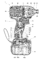
本発明の実施形態1を、図1ないし図3を参照しつつ説明する。図1に示すように、インパクトドライバ1は、本体ハウジング10、ハンマケース20、シール部材50等を備えている。
<Embodiment 1>
Embodiment 1 of the present invention will be described with reference to FIGS. 1 to 3. As shown in FIG. 1, the impact driver 1 includes a main body housing 10, a hammer case 20, a seal member 50, and the like.

図1及び図2に示すように、本体ハウジング10は、樹脂製の左右の半割ハウジング10L、10Rを組み付けて形成されて、胴体部11と、ハンドル部12と、バッテリー装着部13と、リアカバーRとを有する。胴体部11は、筒状に形成されてインパクトドライバ1の前後方向(図1の左右方向)に延設されている。この胴体部11の内部には、モータMが収容されている。また、胴体部11には、モータMの近傍位置に吸気口14A及び排気口14B(図3参照。)がそれぞれ複数設けられている。また、胴体部11の後端部にはリアカバーRが連設されている。このリアカバーRは、胴体部11側を開口させた筒状とされて胴体部11にねじ止めされる。リアカバーRにも吸気口R1(図3参照。)が複数設けられている。これらの吸気口14A、R1は、胴体部11内にモータMの冷却風を吸気するために用いられる。複数の排気口14Bは、前記冷却風を胴体部11外へ排出するために用いられる。なお、本体ハウジング10は本発明のハウジングの一例であり、両半割ハウジング10L、10Rは本発明の2つの分割ハウジングの一例であり、吸気口14A、R1は本発明の開口部の一例である。   As shown in FIGS. 1 and 2, the main body housing 10 is formed by assembling left and right half housings 10L and 10R made of resin, and includes a body portion 11, a handle portion 12, a battery mounting portion 13, and a rear cover. And R. The body part 11 is formed in a cylindrical shape and extends in the front-rear direction of the impact driver 1 (left-right direction in FIG. 1). A motor M is accommodated in the body portion 11. The body portion 11 is provided with a plurality of intake ports 14A and exhaust ports 14B (see FIG. 3) in the vicinity of the motor M. A rear cover R is connected to the rear end portion of the body portion 11. The rear cover R has a cylindrical shape with an opening on the body 11 side and is screwed to the body 11. The rear cover R is also provided with a plurality of intake ports R1 (see FIG. 3). These air inlets 14 </ b> A and R <b> 1 are used to suck the cooling air of the motor M into the body portion 11. The plurality of exhaust ports 14 </ b> B are used for discharging the cooling air out of the body portion 11. The main body housing 10 is an example of the housing of the present invention, the half housings 10L and 10R are examples of the two divided housings of the present invention, and the intake ports 14A and R1 are examples of the opening of the present invention. .

ハンドル部12は、図1ないし図3に示すように、左半割ハウジング10Lの左ハンドル部12Lと、右半割ハウジング10Rの右ハンドル部12Rとを組み付けて形成されている。ハンドル部12は、インパクトドライバ1の側面視で略T字形状となるように胴体部11から連設されている。ハンドル部12の内部には、後述のシール部材50よりもインパクトドライバ1の上下方向の上側に当たる位置に、トリガ15を有する箱状のスイッチSが収容されている。このハンドル部12には、ハンドル部12の根元に当たるバッテリー装着部13との境界付近に当たる位置に排水口17が開設されている。この排水口17はハンドル部12の内部を外部と連通させる。ハンドル部12において、スイッチSが収容された位置や排水口17が開設された位置は、シール部材50を境として前記吸気口14A、R1側に当たる。なお、ハンドル部12の内部で吸気口14A、R1側に当たる位置は、本発明の開口部側のハウジング内の一例である。   As shown in FIGS. 1 to 3, the handle portion 12 is formed by assembling a left handle portion 12L of the left half housing 10L and a right handle portion 12R of the right half housing 10R. The handle portion 12 is continuously provided from the body portion 11 so as to be substantially T-shaped in a side view of the impact driver 1. A box-shaped switch S having a trigger 15 is accommodated inside the handle portion 12 at a position that hits the upper side in the vertical direction of the impact driver 1 with respect to a seal member 50 described later. In the handle portion 12, a drain port 17 is provided at a position near the boundary with the battery mounting portion 13 that is the base of the handle portion 12. The drain port 17 communicates the inside of the handle portion 12 with the outside. In the handle portion 12, the position where the switch S is accommodated and the position where the drain port 17 is opened hit the intake ports 14 </ b> A and R <b> 1 side with the seal member 50 as a boundary. In addition, the position which contacts the inlets 14A and R1 inside the handle portion 12 is an example in the housing on the opening side of the present invention.

図2及び図3に示すように、左ハンドル部12Lの内面にはリブ18Lが突設されて、右ハンドル部12Rの内面にはリブ18Rが突設されている。両リブ18L、18Rは、シール部材50の側面形状に合わせた緩やかなS字形状に成形されている。左右の半割ハウジング10L、10Rの組み付け状態では、リブ18Lとリブ18Rとは、ハンドル部12の左右方向(図2の左右方向)で対向する。リブ18Rには、シール部材50と対向する面でS字形状の上側湾曲部50Aの上端側位置に円柱状の突起部19Aが突出する。加えて、リブ18Rには、シール部材50と対向する面でS字形状の下側湾曲部50Bの下端側位置に円柱状の突起部19Bが突出する。   As shown in FIGS. 2 and 3, a rib 18L protrudes from the inner surface of the left handle portion 12L, and a rib 18R protrudes from the inner surface of the right handle portion 12R. Both ribs 18 </ b> L and 18 </ b> R are formed in a gentle S shape that matches the shape of the side surface of the seal member 50. In the assembled state of the left and right half housings 10L and 10R, the rib 18L and the rib 18R face each other in the left-right direction of the handle portion 12 (left-right direction in FIG. 2). A cylindrical protrusion 19A protrudes from the rib 18R at the upper end side position of the S-shaped upper curved portion 50A on the surface facing the seal member 50. In addition, a cylindrical protrusion 19B protrudes from the rib 18R at the lower end side position of the S-shaped lower curved portion 50B on the surface facing the seal member 50.

バッテリー装着部13は、左半割ハウジング10Lの左バッテリー装着部13Lと、右半割ハウジング10Rの右バッテリー装着部13Rとを組み付けて形成されて、吸気口14A、R1よりも上記の上下方向の下側に当たるハンドル部12の下端に形成されている。バッテリー装着部13には端子台が収容されて、この端子台に略直方体形状のバッテリーパック16が着脱自在に装着される。バッテリーパック16は、充電可能な電源であってトリガ15をハンドル部12内に押し込むことでスイッチSがオン状態になるとモータMへ給電する。また、バッテリー装着部13の背面視左側面には、インパクトドライバ1を作業者のベルトに吊り下げるフックF(図2参照。)が螺着されている。なお、インパクトドライバ1は、本発明の充電式電動工具の一例であり、バッテリー装着部13は本発明の装着部の一例である。またトリガ15は本発明の操作部の一例である。   The battery mounting portion 13 is formed by assembling the left battery mounting portion 13L of the left half housing 10L and the right battery mounting portion 13R of the right half housing 10R. The battery mounting portion 13 is arranged in the vertical direction above the intake ports 14A and R1. It is formed at the lower end of the handle portion 12 that hits the lower side. A terminal block is accommodated in the battery mounting portion 13, and a battery pack 16 having a substantially rectangular parallelepiped shape is detachably mounted on the terminal block. The battery pack 16 is a rechargeable power source, and supplies power to the motor M when the switch S is turned on by pushing the trigger 15 into the handle portion 12. A hook F (see FIG. 2) for hanging the impact driver 1 on the operator's belt is screwed to the left side of the battery mounting portion 13 when viewed from the back. The impact driver 1 is an example of the rechargeable electric tool of the present invention, and the battery mounting part 13 is an example of the mounting part of the present invention. The trigger 15 is an example of the operation unit of the present invention.

ハンマケース20は、金属(例えばアルミニウム)によって形成されて胴体部11の前方(図1の右方向)に組み付けられている。ハンマケース20の内部には、打撃機構やアンビル21が収容されている。ハンマケース20の先端面からはアンビル21が突出する。アンビル21は、軸受によってハンマケース20の内部で回転可能に軸支されている。アンビル21の先端には、先端工具を装着可能なチャック22が設けられている。前記打撃機構は、モータMの回転を回転打撃力に変換して前記先端工具に伝達する。なお、アンビル21は本発明の出力軸の一例である。   The hammer case 20 is formed of metal (for example, aluminum) and is assembled in front of the body portion 11 (right direction in FIG. 1). A hammering mechanism and an anvil 21 are housed inside the hammer case 20. An anvil 21 protrudes from the tip surface of the hammer case 20. The anvil 21 is rotatably supported by the bearing inside the hammer case 20. A chuck 22 to which a tip tool can be attached is provided at the tip of the anvil 21. The striking mechanism converts the rotation of the motor M into a rotational striking force and transmits it to the tip tool. The anvil 21 is an example of the output shaft of the present invention.

カバー30は、ハンマケース20の前方外周で胴体部11から露出する部分に装着されている。バンパー40は、カバー30の前端に組み付けられて前記露出する部分に装着される。カバー30及びバンパー40は、ハンマケース20の前方外周が露出することを防止する。   The cover 30 is attached to a portion exposed from the body part 11 on the front outer periphery of the hammer case 20. The bumper 40 is assembled to the front end of the cover 30 and attached to the exposed portion. The cover 30 and the bumper 40 prevent the front outer periphery of the hammer case 20 from being exposed.

シール部材50は、ハンドル部12内でスイッチSとバッテリーパック16との間に当たる位置に嵌められることで、吸気口14A、R1、ハンドル部12からトリガ15を露出させる開口Hとパッテリーパック16との間に位置する。これにより、ハンドル部12の吸気口14A、R1、開口H側とハンドル部12のバッテリーパック16側との間をシールできる。このシール部材50は、ゴム等の弾性材料によって形成されてハンドル部12の左右方向に厚みを有する。シール部材50の側面形状は緩やかなS字形状とした。   The seal member 50 is fitted between the switch S and the battery pack 16 in the handle portion 12 so that the air intake ports 14A and R1 and the opening H that exposes the trigger 15 from the handle portion 12 and the battery pack 16 are connected. Located between. Thereby, the air inlets 14A and R1 of the handle portion 12 and the space between the opening H side and the battery pack 16 side of the handle portion 12 can be sealed. The seal member 50 is formed of an elastic material such as rubber and has a thickness in the left-right direction of the handle portion 12. The side shape of the sealing member 50 is a gentle S-shape.

図1及び図3に示すように、シール部材50では、S字形状を形成する上側湾曲部50Aの上面が、バッテリー装着部13に装着されたパッテリーパック16の底面16Aに対して前方へ上り傾斜した傾斜面(上側傾斜面)S1となる。この上側傾斜面S1の上端部(前方側端部)には突出部51が形成されている。この突出部51は、上側傾斜面S1に連続して上方(吸気口14A、R1、開口Hが位置する側)へ向けて突出する。シール部材50の上下方向には、突出部51と上側湾曲部50Aとを貫通するリード線通し孔52が形成されている。加えて、突出部51には、上側湾曲部50Aの上端側位置(前方側位置)に貫通孔53Aが形成されている。この貫通孔53Aは突出部51(シール部材50)の厚み方向に形成されており、貫通孔53Aには突起部19Aが挿入可能である。   As shown in FIGS. 1 and 3, in the sealing member 50, the upper surface of the upper curved portion 50 </ b> A that forms an S-shape is inclined upward with respect to the bottom surface 16 </ b> A of the battery pack 16 attached to the battery mounting portion 13. The inclined surface (upper inclined surface) S1. A protrusion 51 is formed at the upper end (front end) of the upper inclined surface S1. The protrusion 51 protrudes upward (on the side where the intake ports 14A, R1 and the opening H are located) continuously to the upper inclined surface S1. In the vertical direction of the seal member 50, a lead wire through hole 52 that penetrates the protruding portion 51 and the upper curved portion 50A is formed. In addition, the protruding portion 51 has a through hole 53A at the upper end side position (front side position) of the upper curved portion 50A. The through hole 53A is formed in the thickness direction of the protruding portion 51 (seal member 50), and the protruding portion 19A can be inserted into the through hole 53A.

一方、S字形状を形成する下側湾曲部50Bの上面は、バッテリー装着部13に装着されたパッテリーパック16の底面16Aに対して後方へ下り傾斜した傾斜面(下側傾斜面)S2となる。図1に示すように、この下側傾斜面S2の下端の際に排水口17が位置する。加えて、下側湾曲部50Bの下端側位置(後方側位置)には貫通孔53Bが形成されている。この貫通孔53Bは貫通孔53Aと同様の方向に形成されており、貫通孔53Bには突起部19Bが挿入可能である。   On the other hand, the upper surface of the lower curved portion 50B that forms the S-shape is an inclined surface (lower inclined surface) S2 that is inclined downward with respect to the bottom surface 16A of the battery pack 16 attached to the battery attachment portion 13. . As shown in FIG. 1, the drain port 17 is located at the lower end of the lower inclined surface S2. In addition, a through hole 53B is formed at the lower end side position (rear side position) of the lower curved portion 50B. The through hole 53B is formed in the same direction as the through hole 53A, and the protrusion 19B can be inserted into the through hole 53B.

図2に示す左右の半割ハウジング10L、10Rの組み付け状態では、突起部19Aが貫通孔53Aに、突起部19Bが貫通孔53Bにそれぞれ挿入された上で、シール部材50の左側面にリブ18L、シール部材50の右側面にリブ18Rがそれぞれ押し付けられる。これにより、シール部材50の左右の側面が弾性変形して両リブ18L、18Rに密着しながら、シール部材50は、ハンドル部12内に嵌められた状態で両リブ18L、18R間に挟まれながら保持される。シール部材50は、ハンドル部12内に保持された状態では上側傾斜面S1及び下側傾斜面S2を有することで、パッテリーパック16の底面16Aに対してバッテリーパック16の後方へ下り傾斜した状態になる。   In the assembled state of the left and right half housings 10L and 10R shown in FIG. 2, the protrusion 19A is inserted into the through hole 53A, the protrusion 19B is inserted into the through hole 53B, and the rib 18L is formed on the left side surface of the seal member 50. The ribs 18R are pressed against the right side surface of the seal member 50, respectively. As a result, the left and right side surfaces of the seal member 50 are elastically deformed and are in close contact with both ribs 18L and 18R, while the seal member 50 is sandwiched between the ribs 18L and 18R while being fitted in the handle portion 12. Retained. The seal member 50 has an upper inclined surface S1 and a lower inclined surface S2 in a state of being held in the handle portion 12, so that the seal member 50 is inclined downward toward the rear of the battery pack 16 with respect to the bottom surface 16A of the battery pack 16. Become.

図1に示すように、ハンドル部12のバッテリーパック16側には雌型コネクタC1が収容されている。雌型コネクタC1に接続されたリード線Lは、リード線通し孔52に挿通されて、ハンドル部12のバッテリーパック16側からハンドル部12の吸気口14A、R1、開口H側へ延長される。ハンドル部12の吸気口14A、R1、開口H側では、スイッチSにリード線Lが電気的に接続されている。スイッチSとモータMとの間には、モータMへ給電するためのリード線(図示せず。)が電気的に接続されている。リード線通し孔52には、リード線Lに加えて通信線(図示せず。)等が隙間なく挿通される。   As shown in FIG. 1, a female connector C <b> 1 is accommodated on the battery pack 16 side of the handle portion 12. The lead wire L connected to the female connector C1 is inserted into the lead wire through hole 52 and extended from the battery pack 16 side of the handle portion 12 to the intake ports 14A, R1 and the opening H side of the handle portion 12. A lead wire L is electrically connected to the switch S on the intake ports 14A, R1 and the opening H side of the handle portion 12. A lead wire (not shown) for supplying power to the motor M is electrically connected between the switch S and the motor M. In addition to the lead wire L, a communication wire (not shown) or the like is inserted into the lead wire through hole 52 without a gap.

雄型コネクタC2は、雌型コネクタC1と結合された状態で、ハンドル部12のバッテリーパック16側に収容されている。雄型コネクタC2に接続されたリード線(図示せず。)は、ハンドル部12の下端側(バッテリー装着部13)へ延長されて端子台と電気的に接続されている。図示のインパクトドライバ1では、両コネクタC1、C2及びリード線L等を介して、スイッチSとバッテリーパック16とが電気的に接続される。本実施形態では、両コネクタC1、C2として非防水構造のコネクタを使用した。これにより、両コネクタC1、C2の大きさは、防水構造のコネクタに比べて小さい。このため、シール部材50、ハンドル部12のバッテリーパック16側の内面、バッテリー装着部13で囲まれたハンドル部12内の狭い空間に、両コネクタC1、C2が収容可能である。なお、スイッチSは本発明の電気部品の一例であり、リード線通し孔52は本発明の挿通孔の一例である。   The male connector C2 is accommodated on the battery pack 16 side of the handle portion 12 in a state of being coupled to the female connector C1. A lead wire (not shown) connected to the male connector C2 extends to the lower end side (battery mounting portion 13) of the handle portion 12 and is electrically connected to the terminal block. In the illustrated impact driver 1, the switch S and the battery pack 16 are electrically connected via the connectors C 1 and C 2, the lead wire L, and the like. In the present embodiment, non-waterproof connectors are used as both connectors C1 and C2. Thereby, the magnitude | size of both connectors C1 and C2 is small compared with the connector of a waterproof structure. For this reason, both the connectors C1 and C2 can be accommodated in a narrow space in the handle portion 12 surrounded by the seal member 50, the inner surface of the handle portion 12 on the battery pack 16 side, and the battery mounting portion 13. The switch S is an example of the electrical component of the present invention, and the lead wire through hole 52 is an example of the insertion hole of the present invention.

本実施形態のインパクトドライバ1では、パッテリーパック16の底面16Aを例えば地面に接して立てた状態で置き忘れたために上記の吸気口14A、R1や開口H(図1参照。)から雨水等が浸入した場合であっても、次のようにしてバッテリーパック16等に雨水等が浸入することを防止できる。吸気口14A、R1から浸入した雨水等は、胴体部11内からハンドル部12の内面とスイッチSとの間の隙間等を通じてシール部材50やリブ18L、18Rに向けて流下する。このとき、シール部材50によって、ハンドル部12の吸気口14A、R1側とバッテリーパック16側との間に隙間が生じることがないため、雨水等が吸気口14A、R1側からバッテリーパック16側へ浸入することが防がれる。   In the impact driver 1 according to the present embodiment, since the bottom surface 16A of the battery pack 16 is misplaced while standing in contact with the ground, for example, rainwater or the like has entered from the intake ports 14A, R1 and the opening H (see FIG. 1). Even in this case, rainwater or the like can be prevented from entering the battery pack 16 or the like as follows. Rainwater or the like that has entered from the intake ports 14A and R1 flows down from the body portion 11 toward the seal member 50 and the ribs 18L and 18R through a gap between the inner surface of the handle portion 12 and the switch S. At this time, since the seal member 50 does not create a gap between the intake port 14A, R1 side of the handle portion 12 and the battery pack 16 side, rainwater or the like flows from the intake port 14A, R1 side to the battery pack 16 side. Intrusion is prevented.

これに加えて、シール部材50に到達した雨水等は、上側傾斜面S1や下側傾斜面S2を流下することで排水口17に導かれる。また、リブ18L、18Rに到達した雨水等は、リブ18L、18Rの上面に沿って排水口17に導かれる。その後、これらの雨水等は、ハンドル部12の内部から排水口17を通過してハンドル部12の外部に排出される。その上、シール部材50に到達した雨水等は、上側傾斜面S1の上り傾斜によって吸気口14A、R1側へ逆流し難くなることに加え、突出部51が逆流の障壁になる。よって、雨水等がリード線通し孔52に向かうことを防止する。また、突出部51がリブ18L、18Rの上面よりも上方へ突出しているため、リブ18L、18Rの上面を流れる雨水等は、突出部51が障壁となってリード線通し孔52に向かうことが阻止される。このため、リード線通し孔52に挿通されたリード線L等を伝って雨水等がハンドル部12のバッテリーパック16側へ浸入することも防止できる。よって、雨水等がリード線Lに接続された雌型コネクタC1や雄型コネクタC2に向けて流れることを防止することで、両コネクタC1、C2に対する防水性が向上する。   In addition, rainwater or the like that reaches the seal member 50 is guided to the drain port 17 by flowing down the upper inclined surface S1 or the lower inclined surface S2. In addition, rainwater or the like that has reached the ribs 18L and 18R is guided to the drain port 17 along the upper surfaces of the ribs 18L and 18R. Thereafter, these rainwater and the like pass through the drain port 17 from the inside of the handle portion 12 and are discharged to the outside of the handle portion 12. In addition, rainwater or the like that has reached the seal member 50 is unlikely to flow back to the intake ports 14A and R1 due to the upward inclination of the upper inclined surface S1, and the protruding portion 51 becomes a reverse flow barrier. Therefore, rainwater or the like is prevented from moving toward the lead wire through hole 52. Further, since the protruding portion 51 protrudes upward from the upper surfaces of the ribs 18L and 18R, rainwater and the like flowing on the upper surfaces of the ribs 18L and 18R may go to the lead wire through hole 52 with the protruding portion 51 serving as a barrier. Be blocked. For this reason, it is possible to prevent rainwater or the like from entering the battery pack 16 side of the handle portion 12 through the lead wire L or the like inserted into the lead wire through hole 52. Therefore, by preventing rainwater and the like from flowing toward the female connector C1 and the male connector C2 connected to the lead wire L, the waterproof property for both the connectors C1 and C2 is improved.

一方、開口Hから浸入した雨水等も、吸気口14A、R1から浸入した雨水等と同様に、吸気口14A、R1、開口H側からバッテリーパック16側へ浸入することが防がれる。これに加えて、開口Hから浸入した雨水等は、吸気口14A、R1から浸入した雨水等と同様にして排水口17に導かれる。その後、前記雨水等はハンドル部12の外部に排出される。その上、開口Hから浸入した雨水等は、吸気口14A、R1から浸入した雨水等と同様に、リード線通し孔52に向かうことが阻止される。よって、開口Hから浸入した雨水等は、吸気口14A、R1から浸入した雨水等と同様に、バッテリーパック16側へ浸入することを防止できる。なお、開口Hは本発明の開口部の一例である。   On the other hand, rainwater or the like entering from the opening H is prevented from entering the battery pack 16 side from the inlets 14A and R1 or the opening H side, similarly to rainwater or the like entering from the inlets 14A and R1. In addition to this, rainwater or the like entering from the opening H is guided to the drain port 17 in the same manner as rainwater or the like entering from the intake ports 14A and R1. Thereafter, the rainwater and the like are discharged to the outside of the handle portion 12. In addition, rainwater or the like that has entered from the opening H is prevented from heading to the lead wire through-hole 52, similarly to rainwater or the like that has entered from the intake ports 14A and R1. Therefore, rainwater or the like entering from the opening H can be prevented from entering the battery pack 16 side, similarly to rainwater or the like entering from the intake ports 14A and R1. The opening H is an example of the opening of the present invention.

<実施形態1の効果>
本実施形態のインパクトドライバ1では、ハンドル部12内で、シール部材50が、吸気口14A、R1、開口Hと、吸気口14A、R1、開口Hよりもインパクトドライバ1の上下方向の下側に位置するバッテリー装着部13に装着したパッテリーパック16との間をシールする。このため、雨水等が吸気口14A、R1から胴体部11を通じてハンドル部12に向って流下したり、雨水等が開口Hから浸入してハンドル部12の内面に沿って流下しても、シール部材50によって、バッテリー装着部13とパッテリーパック16との隙間やパッテリーパック16に雨水等が浸入することを防止できる。これにより、前記隙間やバッテリーパック16に対する防水性を向上させることができる。
<Effect of Embodiment 1>
In the impact driver 1 according to the present embodiment, the seal member 50 is located on the lower side in the vertical direction of the impact driver 1 with respect to the intake ports 14A, R1, and the opening H and the intake ports 14A, R1, and the opening H in the handle portion 12. A gap between the battery pack 16 and the battery pack 16 mounted on the battery mounting portion 13 is sealed. Therefore, even if rainwater or the like flows down from the intake ports 14A and R1 through the body portion 11 toward the handle portion 12 or rainwater enters from the opening H and flows down along the inner surface of the handle portion 12, the seal member 50 prevents rainwater or the like from entering the gap between the battery mounting portion 13 and the battery pack 16 or the battery pack 16. Thereby, the waterproofness with respect to the said clearance gap and the battery pack 16 can be improved.

また、吸気口14A、R1から浸入した雨水等は、胴体部11内からハンドル部12の内面とスイッチSとの間の隙間等を通じてシール部材50に流下しても、突出部51によって、雨水等が吸気口14A、R1側へ逆流することを妨げてリード通し孔52に向かうことを防止できる。加えて、上述したように、開口Hから浸入した雨水等も、突出部51によって、吸気口14A、R1、開口H側へ逆流することを妨げてリード通し孔52に向かうことを防止できる。これにより、雨水等がリード線通し孔52に挿通されたリード線L等を伝ってバッテリーパック16側へ浸入することを防止できる。   Even if rainwater or the like that has entered from the air inlets 14A and R1 flows down from the inside of the body portion 11 to the seal member 50 through a gap between the inner surface of the handle portion 12 and the switch S, rainwater or the like is caused by the protrusion 51. Can be prevented from flowing back to the intake port 14A, R1 side and heading toward the lead through hole 52. In addition, as described above, rainwater or the like that has entered from the opening H can be prevented from flowing back to the inlets 14A, R1, and the opening H side by the protruding portion 51 and heading toward the lead through hole 52. Accordingly, rainwater or the like can be prevented from entering the battery pack 16 side through the lead wire L or the like inserted through the lead wire through hole 52.

さらに、左右の半割ハウジング10L、10Rの組み付け状態では、シール部材50は、ハンドル部12内に両リブ18L、18R間に挟まれながら保持される。このため、シール部材50が両リブ18L、18R間に押さえられてがたつくことがなく、ハンドル部12内でシール部材50が移動することを防止できる。これにより、ハンドル部12内でのシール部材50の位置決めが良好になる。   Further, in the assembled state of the left and right half housings 10L and 10R, the seal member 50 is held in the handle portion 12 while being sandwiched between the ribs 18L and 18R. For this reason, the seal member 50 is not rattled by being pressed between the ribs 18L and 18R, and the seal member 50 can be prevented from moving in the handle portion 12. Thereby, the positioning of the seal member 50 in the handle portion 12 becomes good.

さらに加えて、ハンドル部12の吸気口14A、R1、開口H側に当たる位置に排水口17を開設し、シール部材50の下側傾斜面S2の下端の際に排水口17が位置する。このため、吸気口14A、R1や開口Hから浸入した雨水等がハンドル部12内を流下しても、シール部材50に到達した雨水等は、上側傾斜面S1や下側傾斜面S2を流下することで、排水口17からハンドル部12の外部に排出される。これにより、吸気口14A、R1や開口Hから浸入した雨水等が、前記隙間やバッテリーパック16に浸入することを防止できる。   In addition, the drain port 17 is opened at a position corresponding to the intake ports 14A, R1 and the opening H side of the handle portion 12, and the drain port 17 is positioned at the lower end of the lower inclined surface S2 of the seal member 50. For this reason, even if rainwater or the like entering from the intake ports 14A and R1 or the opening H flows down in the handle portion 12, the rainwater or the like that reaches the seal member 50 flows down the upper inclined surface S1 or the lower inclined surface S2. As a result, the water is discharged from the drain port 17 to the outside of the handle portion 12. Accordingly, rainwater or the like that has entered from the air inlets 14 </ b> A and R <b> 1 or the opening H can be prevented from entering the gap or the battery pack 16.

<実施形態2>
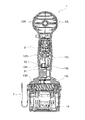
本発明の実施形態2を、図4ないし図6を参照しつつ説明する。ここでは実施形態1と同一の構成は同一の符号を付しその説明を省略し、実施形態1と同じ効果についてもその記載を省略する。また図4にはリード線Lの図示を省略したが、本実施形態のインパクトドライバ1Aでも、実施形態1と同様のリード線Lを備えている。インパクトドライバ1Aは、熱収縮チューブ55と、単泡スポンジ56(56A、56B)と、シール部材60とを備えている。熱収縮チューブ55の内周面には接着剤が塗布されている。熱収縮チューブ55は、リード線Lや通信線L1に装着された後に加熱されることで収縮してリード線L等に密着する。これにより、図5及び図6に示すように、熱収縮チューブ55はリード線Lや通信線L1を被覆する。これと同時に接着剤が溶けてリード線Lや通信線L1との間に流れ込む。そして、この接着剤が冷却後に硬化することで、熱収縮チューブ55とリード線Lや通信線L1との間が密閉される。
<Embodiment 2>
A second embodiment of the present invention will be described with reference to FIGS. Here, the same components as those of the first embodiment are denoted by the same reference numerals, and the description thereof is omitted. The description of the same effects as those of the first embodiment is also omitted. Although the lead wire L is not shown in FIG. 4, the impact driver 1 </ b> A of the present embodiment also includes the lead wire L similar to that of the first embodiment. The impact driver 1A includes a heat-shrinkable tube 55, single foam sponges 56 (56A, 56B), and a seal member 60. An adhesive is applied to the inner peripheral surface of the heat shrinkable tube 55. The heat-shrinkable tube 55 is heated after being attached to the lead wire L or the communication wire L1, and contracts by being heated and closely contacts the lead wire L or the like. Thereby, as shown in FIG.5 and FIG.6, the heat-shrinkable tube 55 coat | covers the lead wire L and the communication wire L1. At the same time, the adhesive melts and flows between the lead wire L and the communication wire L1. The adhesive is cured after cooling, so that the space between the heat shrinkable tube 55 and the lead wire L or the communication wire L1 is sealed.

単泡スポンジ56Aは、その上下方向に延設された上で側面側に開口する凹溝57を備えている。シール部材60の突出部51には、シール部材60の上下方向へ延設された凹溝61が形成されている。単泡スポンジ56Aは、左右方向において先端部分を凹溝61から突出させた状態で凹溝61に嵌合されている。図6に示すように、単泡スポンジ56Bは、ハンドル部12Lの内面に向けて開口する凹溝58が形成されたコ字型の断面形状を有する。単泡スポンジ56Bは、平面視が略長方形状で単泡スポンジ56Bの基端側から凹溝57内に嵌め入れられている。   The single foam sponge 56A is provided with a concave groove 57 that extends in the vertical direction and opens to the side surface. A concave groove 61 extending in the vertical direction of the seal member 60 is formed in the protruding portion 51 of the seal member 60. The single foam sponge 56 </ b> A is fitted in the concave groove 61 in a state where the tip portion protrudes from the concave groove 61 in the left-right direction. As shown in FIG. 6, the single foam sponge 56B has a U-shaped cross-sectional shape in which a concave groove 58 that opens toward the inner surface of the handle portion 12L is formed. The single foam sponge 56B has a substantially rectangular shape in plan view and is fitted into the groove 57 from the base end side of the single foam sponge 56B.

左右の半割ハウジング10L、10Rを組み付ける前に、熱収縮チューブ55で被覆されたリード線Lや通信線L1を、単泡スポンジ56Aの凹溝57内を通してシール部材60を貫通させて、スイッチSと雌型コネクタC1との間を電気的に接続する。図5及び図6に示すように、左右の半割ハウジング10L、10Rを組み付けると、リブ18Rがシール部材60の右側面に押し付けられる。これと共に、リブ18Lが単泡スポンジ56Bの凹溝58に嵌り込んだ状態で単泡スポンジ56Bを熱収縮チューブ55に押し付ける。このとき、リブ18Lは単泡スポンジ56Aを変形させて単泡スポンジ56Aに密着する。その結果、単泡スポンジ56Aと単泡スポンジ56Bとが熱収縮チューブ55の外周面に圧接することで、熱収縮チューブ55が単泡スポンジ56Aや単泡スポンジ56Bと対向する面はシールされる。なお、熱収縮チューブ55は本発明の被覆部材の一例であり、単泡スポンジ56A、56Bは本発明の弾性部材の一例である。   Before assembling the left and right half housings 10L and 10R, the lead wire L and the communication wire L1 covered with the heat shrinkable tube 55 are passed through the recessed groove 57 of the single-foam sponge 56A, and the seal member 60 is penetrated. And the female connector C1 are electrically connected. As shown in FIGS. 5 and 6, when the left and right half housings 10 </ b> L and 10 </ b> R are assembled, the rib 18 </ b> R is pressed against the right side surface of the seal member 60. At the same time, the single foam sponge 56B is pressed against the heat shrinkable tube 55 in a state where the rib 18L is fitted in the concave groove 58 of the single foam sponge 56B. At this time, the rib 18L deforms the single foam sponge 56A and comes into close contact with the single foam sponge 56A. As a result, the single foam sponge 56A and the single foam sponge 56B are pressed against the outer peripheral surface of the heat shrinkable tube 55, and the surface of the heat shrinkable tube 55 that faces the single foam sponge 56A and the single foam sponge 56B is sealed. The heat shrinkable tube 55 is an example of the covering member of the present invention, and the single foam sponges 56A and 56B are examples of the elastic member of the present invention.

本実施形態では、雨水等が吸気口14A、R1や開口Hを通じて仮にリード線Lや通信線L1に到達した場合でも、次のようにしてバッテリーパック16側へ雨水等が浸入することを防止できる。熱収縮チューブ55とリード線Lや通信線L1との間には隙間がないため、リード線Lや通信線L1を伝って熱収縮チューブ55に向かう雨水等は、熱収縮チューブ55とリード線L等との間を通過できず、ハンドル部12のバッテリーパック16側へ浸入することができない。さらに、熱収縮チューブ55が単泡スポンジ56Aや単泡スポンジ56Bと対向する面はシールされているため、熱収縮チューブ55と各単泡スポンジ56A、56Bとの間にも隙間がない。したがって、リード線Lや通信線L1を伝う雨水等は、熱収縮チューブ55と各単泡スポンジ56A、56Bとの間も通過できず、ハンドル部12のバッテリーパック16側へ浸入することができない。   In the present embodiment, even when rainwater or the like reaches the lead wire L or the communication line L1 through the air inlets 14A, R1 and the opening H, rainwater and the like can be prevented from entering the battery pack 16 as follows. . Since there is no gap between the heat-shrinkable tube 55 and the lead wire L or the communication wire L1, rainwater or the like traveling to the heat-shrinkable tube 55 through the lead wire L or the communication wire L1 Etc., and cannot enter the battery pack 16 side of the handle portion 12. Further, since the surface of the heat shrinkable tube 55 facing the single foam sponge 56A and the single foam sponge 56B is sealed, there is no gap between the heat shrinkable tube 55 and each single foam sponge 56A, 56B. Accordingly, rainwater or the like transmitted through the lead wire L or the communication line L1 cannot pass between the heat shrinkable tube 55 and the single foam sponges 56A and 56B, and cannot enter the battery pack 16 side of the handle portion 12.

<実施形態2の効果>
本実施形態のインパクトドライバ1Aでは、熱収縮チューブ55はリード線Lや通信線L1に密着してリード線L等を被覆することで熱収縮チューブ55とリード線L等との間に隙間がなくなる。このため、吸気口14A、R1や開口Hから浸入した雨水等が、熱収縮チューブ55とリード線L等との間からバッテリー装着部13とパッテリーパック16との隙間やパッテリーパック16に向けて流れることを防止できる。
これに加えて、熱収縮チューブ55が単泡スポンジ56Aや単泡スポンジ56Bと対向する面をシールすることで、熱収縮チューブ55と各単泡スポンジ56A、56Bとの間にも隙間がなくなる。このため、前記雨水等が熱収縮チューブ55と各単泡スポンジ56A、56Bとの間からバッテリー装着部13とパッテリーパック16との隙間やパッテリーパック16に向けて流れることも防止できる。
<Effect of Embodiment 2>
In the impact driver 1A of the present embodiment, the heat shrinkable tube 55 is in close contact with the lead wire L or the communication wire L1 so as to cover the lead wire L or the like so that there is no gap between the heat shrinkable tube 55 and the lead wire L or the like. . For this reason, rainwater or the like that has entered from the air inlets 14A, R1 or the opening H flows from between the heat shrinkable tube 55 and the lead wire L toward the gap between the battery mounting portion 13 and the battery pack 16 or toward the battery pack 16. Can be prevented.
In addition, since the heat-shrinkable tube 55 seals the surface facing the single-bubble sponge 56A or single-bubble sponge 56B, there is no gap between the heat-shrinkable tube 55 and each single-bubble sponge 56A, 56B. For this reason, it is possible to prevent the rainwater and the like from flowing between the heat shrinkable tube 55 and the single foam sponges 56 </ b> A and 56 </ b> B toward the gap between the battery mounting portion 13 and the battery pack 16 or toward the battery pack 16.

<実施形態3>
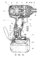
本発明の実施形態3を、図7及び図8を参照しつつ説明する。ここでは、実施形態1、2と同一の構成は同一の符号を付しその説明を省略する。本実施形態のインパクトドライバ1Bは、実施形態1、2とは異なりリアカバーRを設けることなく胴体部11Aを筒状に形成した。インパクトドライバ1Bはシール部材70を備えている。シール部材70はゴム等の弾性材料によって形成されている。図7に示すように、シール部材70は、ハンドル部12内でスイッチSの外周面に巻き付けた状態で吸気口14A、開口Hとバッテリーパック16との間に当たる位置に嵌められている。これにより、ハンドル部12の吸気口14A、開口H側とハンドル部12のバッテリーパック16側との間をシールする。このシール部材70は、パッテリーパック16の底面16Aに対してパッテリーパック16の前方へ下り傾斜した状態で前記外周面に巻き付けられている。シール部材70の全周にはリブ案内溝71が設けられている。また図8に示すように、左ハンドル部12Lの内面の全周に亘って薄板状のリブ18L1が突設されて、右ハンドル部12Rの内面の全周に亘って薄板状のリブ18R1が突設されている。各リブ18L1、18R1は、前記底面16Aに対して前方へ下り傾斜した平面上に配置されている。
<Embodiment 3>
Embodiment 3 of the present invention will be described with reference to FIGS. Here, the same configurations as those of the first and second embodiments are denoted by the same reference numerals, and the description thereof is omitted. Unlike the first and second embodiments, the impact driver 1 </ b> B of the present embodiment has the body portion 11 </ b> A formed in a cylindrical shape without providing the rear cover R. The impact driver 1B includes a seal member 70. The seal member 70 is made of an elastic material such as rubber. As shown in FIG. 7, the seal member 70 is fitted at a position where the seal member 70 is in contact with the air inlet 14 </ b> A, the opening H, and the battery pack 16 while being wound around the outer peripheral surface of the switch S in the handle portion 12. As a result, the air inlet 14A and the opening H side of the handle portion 12 and the battery pack 16 side of the handle portion 12 are sealed. The seal member 70 is wound around the outer peripheral surface in a state where the seal member 70 is inclined downward toward the front of the battery pack 16 with respect to the bottom surface 16 </ b> A of the battery pack 16. Rib guide grooves 71 are provided on the entire circumference of the seal member 70. Further, as shown in FIG. 8, a thin plate-like rib 18L1 protrudes over the entire inner periphery of the left handle portion 12L, and a thin plate-like rib 18R1 protrudes over the entire inner periphery of the right handle portion 12R. It is installed. Each of the ribs 18L1 and 18R1 is disposed on a plane inclined downward and forward with respect to the bottom surface 16A.

左右の半割ハウジング10L、10Rを組み付けるときに、シール部材70をスイッチSの外周面に巻き付けた状態でトリガ15を開口Hから露出させながら、リブ18L1、18R1をリブ案内溝71に係合することで、スイッチSをハンドル部12内に収容する。これに伴って、シール部材70はハンドル部12内に位置決めされた上で保持される。このとき、シール部材70の傾斜下端側が開口Hに向かうように配置される。   When the left and right half housings 10L and 10R are assembled, the ribs 18L1 and 18R1 are engaged with the rib guide grooves 71 while the trigger 15 is exposed from the opening H while the seal member 70 is wound around the outer peripheral surface of the switch S. Thus, the switch S is accommodated in the handle portion 12. Accordingly, the seal member 70 is held after being positioned in the handle portion 12. At this time, it arrange | positions so that the inclination lower end side of the sealing member 70 may go to the opening H. FIG.

本実施形態では、雨水等が吸気口14A、開口Hを通じてハンドル部12内に浸入した場合でも、次のようにしてバッテリーパック16側へ雨水等が浸入することを防止できる。シール部材70によって、吸気口14A、開口H側とハンドル部12のバッテリーパック16側との間に隙間がないため、雨水等は吸気口14A、開口H側からバッテリーパック16側へ浸入することができない。これに加えて、シール部材70に到達した雨水等は、シール部材70の上面を流下することで開口Hに導かれた後に開口Hを通過してハンドル部12の外部に排出される。これにより、前記雨水等はハンドル部12のバッテリーパック16側へ浸入することができない。   In the present embodiment, even when rainwater or the like enters the handle portion 12 through the intake port 14A and the opening H, rainwater or the like can be prevented from entering the battery pack 16 as follows. Since there is no gap between the intake port 14A and the opening H side and the battery pack 16 side of the handle portion 12 by the sealing member 70, rainwater and the like can enter the battery pack 16 side from the intake port 14A and the opening H side. Can not. In addition to this, rainwater or the like that has reached the seal member 70 flows down the upper surface of the seal member 70, is guided to the opening H, passes through the opening H, and is discharged to the outside of the handle portion 12. Accordingly, the rainwater or the like cannot enter the battery pack 16 side of the handle portion 12.

<実施形態3の効果>
本実施形態のインパクトドライバ1Bでは、シール部材70をスイッチSの外周面に巻き付けて、シール部材70をリブ案内溝71を用いてリブ18L1、18R1に係合させながらスイッチSをハンドル部12内に収容するだけで、シール部材70をハンドル部12内に位置決め可能となる。よって、シール部材70の位置決め作業が容易になる。
<Effect of Embodiment 3>
In the impact driver 1B of this embodiment, the seal member 70 is wound around the outer peripheral surface of the switch S, and the switch S is moved into the handle portion 12 while the seal member 70 is engaged with the ribs 18L1 and 18R1 using the rib guide groove 71. The sealing member 70 can be positioned in the handle portion 12 simply by being accommodated. Therefore, the positioning operation of the seal member 70 is facilitated.

さらに、実施形態1、2とは異なり排水口17を新たにハンドル部12に開設しなくても開口Hを利用することで、吸気口14A、開口Hを通じてハンドル部12内に浸入した雨水等が、開口Hからハンドル部12の外部に排出されてバッテリー装着部13とパッテリーパック16との隙間やパッテリーパック16に浸入することを防止できる。   Further, unlike Embodiments 1 and 2, by using the opening H without newly opening the drain port 17 in the handle portion 12, rainwater or the like that has entered the handle portion 12 through the intake port 14A and the opening H can be obtained. Thus, it is possible to prevent the battery from being discharged from the opening H to the outside of the handle portion 12 and entering the gap between the battery mounting portion 13 and the battery pack 16 or the battery pack 16.

本発明は、上述した実施形態に限定されるものではなく、発明の趣旨を逸脱しない範囲内において構成の一部を適宜変更して実施できる。実施形態1、2とは異なり、シール部材は、S字状の側面形状を有するものに限らず、例えば、吸気口14A、R1、開口H側からバッテリーパック16側に向けて直線状に傾斜した側面形状等を有するものであってもよい。   The present invention is not limited to the above-described embodiment, and can be implemented by appropriately changing a part of the configuration without departing from the spirit of the invention. Unlike Embodiments 1 and 2, the seal member is not limited to one having an S-shaped side surface shape, and, for example, is linearly inclined from the inlets 14A, R1 and the opening H side toward the battery pack 16 side. It may have a side shape or the like.

また、シール部材が直線状に傾斜した側面形状等を有する場合には、上述した実施形態とは異なり、各ハンドル部12L、12Rに突設するリブの形状を、直線状に傾斜した側面等をそれぞれ押圧可能な適宜の形状に変更してもよい。加えて、上述した実施形態とは異なり、シール部材70の全周に設けた凸部を両ハンドル部12L、12Rの全周に設けた凹部に係合させることで、スイッチSをハンドル部12内に収容してもよい。これ以外にも、シール部材70に凸部を設けることなく、シール部材70を両ハンドル部12L、12Rの全周に設けた凹部に直接嵌合させることで、スイッチSをハンドル部12内に収容してもよい。さらに、上述したインパクトドライバ1、1A、1Bに限らず、充電式のハンマドリル等の電動工具に本発明を適用してもよい。   Further, when the sealing member has a linearly inclined side surface shape or the like, unlike the above-described embodiment, the ribs projecting from the handle portions 12L and 12R have a linearly inclined side surface or the like. You may change into the appropriate shape which can be pressed, respectively. In addition, unlike the embodiment described above, the switch S is disposed in the handle portion 12 by engaging the convex portions provided on the entire circumference of the seal member 70 with the concave portions provided on the entire circumference of the handle portions 12L and 12R. May be accommodated. In addition to this, the switch S is accommodated in the handle portion 12 by directly fitting the seal member 70 into the recesses provided on the entire circumferences of the handle portions 12L and 12R without providing the seal member 70 with a convex portion. May be. Furthermore, you may apply this invention not only to the impact driver 1, 1A, 1B mentioned above but to electric tools, such as a rechargeable hammer drill.

1、1A、1B・・インパクトドライバ、10・・本体ハウジング、10L・・左半割ハウジング、10R・・右半割ハウジング、13・・バッテリー装着部、14A、R1・・吸気口、15・・トリガ、16・・バッテリーパック、16A・・バッテリーパックの底面、17・・排水口、18L、18R・・リブ、21・・アンビル、50、60、70・・シール部材、51・・突出部、52・・リード線通し孔、55・・熱収縮チューブ、56A、56B・・単泡スポンジ、H・・開口、L・・リード線、R・・リアカバー、S・・スイッチ。   1, 1A, 1B ··· Impact driver, 10 · · Body housing, 10L · · Left half housing, 10R · · Right half housing, 13 · · Battery mounting portion, 14A, R1 · · Inlet, ··· Trigger, 16 ... Battery pack, 16A ... Bottom of battery pack, 17 ... Drain port, 18L, 18R ... Rib, 21 ... Anvil, 50, 60, 70 ... Sealing member, 51 ... Projection, 52 .... Lead wire through hole, 55 ... Heat shrink tube, 56A, 56B ... Single foam sponge, H ... Open, L ... Lead wire, R ... Rear cover, S ... Switch.

Claims (3)

前後方向に延設された胴体部と、前記胴体部から該胴体部の下方に延びるハンドル部と、前記ハンドル部の下端に形成されて電源となるバッテリーパックを着脱自在に装着するバッテリー装着部と、を有する本体ハウジングと、
前記胴体部の内部に収容されたモータと、
前記胴体部に設けられて、前記モータの冷却風を吸気する吸気口と、
前記胴体部に設けられて、前記冷却風を前記胴体部の外部へ排出する排気口と、
前記胴体部に、前記モータの前方で組み付けられて、先端工具を装着可能で前記モータの回転が伝達されるチャックと、
前記ハンドル部の内部に収容されて、該ハンドル部から露出して前記ハンドル部の内部に押し込み可能なトリガを有して、前記バッテリーパックから前記モータへの電力供給を制御するスイッチと、を備えた充電式電動工具であって、
前記ハンドル部に、前記トリガを該ハンドル部から露出させる開口を設け、前記スイッチの外面に対して前記ハンドル部の内部の前記胴体部側と該ハンドル部の内部の前記バッテリー装着部側との間をシールするように配置した弾性体を、前記開口に向かうように下り傾斜させて、
前記吸気口と前記排気口との少なくとも一方から前記胴体部の内部に浸入した水を、前記ハンドル部の内部を通過させて前記弾性体によって前記開口に導いて、前記開口から前記ハンドル部の外部へ排出可能としたことを特徴とする充電式電動工具。
A body portion extending in the front-rear direction, a handle portion extending from the body portion to the lower portion of the body portion, and a battery attachment portion that is detachably attached to a battery pack that is formed at a lower end of the handle portion and serves as a power source. A body housing having
A motor housed in the body part;
An intake port provided in the body portion for intake of cooling air of the motor;
An exhaust port provided in the body part for discharging the cooling air to the outside of the body part;
A chuck that is assembled to the body portion in front of the motor, can be fitted with a tip tool, and the rotation of the motor is transmitted thereto;
A switch that is housed in the handle portion, has a trigger that is exposed from the handle portion and can be pushed into the handle portion, and controls power supply from the battery pack to the motor. Rechargeable electric tool,
Said handle portion, said trigger an opening for exposing from the handle portion, between the battery mounting section side of the interior of the body portion side and the handle portion of the interior of the handle portion for the outer surface of the switch The elastic body arranged so as to seal is inclined downward toward the opening,
Water that has entered the body portion from at least one of the intake port and the exhaust port passes through the inside of the handle portion and is guided to the opening by the elastic body, and from the opening to the outside of the handle portion. Rechargeable power tool characterized by being able to discharge to
前記弾性体は、前記スイッチの上下方向の一部で前記外面に沿って配置されたことを特徴とする請求項1に記載の充電式電動工具。   The rechargeable electric tool according to claim 1, wherein the elastic body is disposed along the outer surface at a part in a vertical direction of the switch. 前記弾性体は、前記外面に沿って前記下り傾斜させた状態で前記スイッチの前後方向に延びるように配置されたことを特徴とする請求項1又は2に記載の充電式電動工具。 The rechargeable electric tool according to claim 1, wherein the elastic body is disposed so as to extend in the front-rear direction of the switch in a state where the elastic body is inclined downward along the outer surface.
JP2012222346A 2010-09-28 2012-10-04 Rechargeable power tool Active JP5518159B2 (en)

Priority Applications (1)

Application Number Priority Date Filing Date Title
JP2012222346A JP5518159B2 (en) 2010-09-28 2012-10-04 Rechargeable power tool

Applications Claiming Priority (3)

Application Number Priority Date Filing Date Title
JP2010217589 2010-09-28
JP2012222346A JP5518159B2 (en) 2010-09-28 2012-10-04 Rechargeable power tool

Related Parent Applications (1)

Application Number Title Priority Date Filing Date
JP2011002143A Division JP5722638B2 (en) 2010-09-28 2011-01-07 Rechargeable power tool

Publications (3)

Publication Number Publication Date
JP2012254526A JP2012254526A (en) 2012-12-27
JP2012254526A5 JP2012254526A5 (en) 2013-07-11
JP5518159B2 true JP5518159B2 (en) 2014-06-11

Family

ID=47526589

Family Applications (2)

Application Number Title Priority Date Filing Date
JP2012222346A Active JP5518159B2 (en) 2010-09-28 2012-10-04 Rechargeable power tool
JP2015022453A Active JP5969067B2 (en) 2010-09-28 2015-02-06 Rechargeable power tool

Family Applications After (1)

Application Number Title Priority Date Filing Date
JP2015022453A Active JP5969067B2 (en) 2010-09-28 2015-02-06 Rechargeable power tool

Country Status (1)

Country Link
JP (2) JP5518159B2 (en)

Families Citing this family (4)

* Cited by examiner, † Cited by third party
Publication number Priority date Publication date Assignee Title
JP6169437B2 (en) 2013-08-13 2017-07-26 株式会社マキタ Electric tool
JP6655958B2 (en) * 2015-01-29 2020-03-04 株式会社マキタ Hammer drill or electric hammer, power tool
JP6101394B2 (en) * 2016-09-09 2017-03-22 株式会社マキタ Battery pack
JP6808454B2 (en) * 2016-11-17 2021-01-06 株式会社マキタ Portable cutting machine for woodworking

Family Cites Families (7)

* Cited by examiner, † Cited by third party
Publication number Priority date Publication date Assignee Title
JPS586092Y2 (en) * 1977-04-15 1983-02-02 日立工機株式会社 Switch vibration isolation device
US7152695B2 (en) * 2002-09-20 2006-12-26 Snap-On Incorporated Power tool with air seal and vibration dampener
JP4300990B2 (en) * 2003-12-09 2009-07-22 パナソニック電工株式会社 Rotating tool
JP4466388B2 (en) * 2005-01-26 2010-05-26 パナソニック電工株式会社 Electric tool
JP2007268634A (en) * 2006-03-30 2007-10-18 Max Co Ltd Power tool
DE102006020172A1 (en) * 2006-05-02 2007-11-08 Robert Bosch Gmbh Hand tool
TW201006623A (en) * 2008-08-08 2010-02-16 Cheng Huan Industry Ltd Pneumatic tool with multi-stage torque adjusting function

Also Published As

Publication number Publication date
JP2015110268A (en) 2015-06-18
JP5969067B2 (en) 2016-08-10
JP2012254526A (en) 2012-12-27

Similar Documents

Publication Publication Date Title
JP5722638B2 (en) Rechargeable power tool
US7770660B2 (en) Mid-handle drill construction and assembly process
JP5969067B2 (en) Rechargeable power tool
JP5728303B2 (en) Impact tool
US8733471B2 (en) Rechargeable electric tool
EP2332697B1 (en) Hook for electric power tools and electric power tool equipped with the hook
JP2012091309A5 (en)
EP2956275B1 (en) Electric device body and electric device
US20110220381A1 (en) Electrical appliance, in particular hand-held power tool
US20050257945A1 (en) Motor housing and assembly process for impact wrench
JP3674308B2 (en) Electric tool
JP2019076994A (en) Electric tool
JP2017226025A (en) Electric tool
JP2014061557A (en) Electric tool
JP2019217569A (en) Electric power tool
JP2008080421A (en) Hand-held tool
JP6945155B2 (en) Electric tool
JP4049128B2 (en) Tabletop
US20230107123A1 (en) Power tool
JP2022021558A (en) Chain saw
JP4698138B2 (en) Electric razor
CN114027738A (en) Water tank structure and cleaning robot

Legal Events

Date Code Title Description
A621 Written request for application examination

Free format text: JAPANESE INTERMEDIATE CODE: A621

Effective date: 20121009

A521 Request for written amendment filed

Free format text: JAPANESE INTERMEDIATE CODE: A523

Effective date: 20130529

A977 Report on retrieval

Free format text: JAPANESE INTERMEDIATE CODE: A971007

Effective date: 20131025

A131 Notification of reasons for refusal

Free format text: JAPANESE INTERMEDIATE CODE: A131

Effective date: 20131105

RD13 Notification of appointment of power of sub attorney

Free format text: JAPANESE INTERMEDIATE CODE: A7433

Effective date: 20131122

A521 Request for written amendment filed

Free format text: JAPANESE INTERMEDIATE CODE: A523

Effective date: 20131211

Free format text: JAPANESE INTERMEDIATE CODE: A821

Effective date: 20131125

TRDD Decision of grant or rejection written
A01 Written decision to grant a patent or to grant a registration (utility model)

Free format text: JAPANESE INTERMEDIATE CODE: A01

Effective date: 20140304

A61 First payment of annual fees (during grant procedure)

Free format text: JAPANESE INTERMEDIATE CODE: A61

Effective date: 20140401

R150 Certificate of patent or registration of utility model

Ref document number: 5518159

Country of ref document: JP

Free format text: JAPANESE INTERMEDIATE CODE: R150

R250 Receipt of annual fees

Free format text: JAPANESE INTERMEDIATE CODE: R250

R250 Receipt of annual fees

Free format text: JAPANESE INTERMEDIATE CODE: R250

R250 Receipt of annual fees

Free format text: JAPANESE INTERMEDIATE CODE: R250

R250 Receipt of annual fees

Free format text: JAPANESE INTERMEDIATE CODE: R250

R250 Receipt of annual fees

Free format text: JAPANESE INTERMEDIATE CODE: R250

R250 Receipt of annual fees

Free format text: JAPANESE INTERMEDIATE CODE: R250

R250 Receipt of annual fees

Free format text: JAPANESE INTERMEDIATE CODE: R250

R250 Receipt of annual fees

Free format text: JAPANESE INTERMEDIATE CODE: R250